


RCF2760
Table of contents
 Loading...
Table of Contents
Cover photo may show optional equipment
not supplied with standard unit.
Read the Operator’s Manual entirely. When you
see this symbol, the subsequent instructions and
warnings are serious - follow without exception.
Your life and the lives of others depend on it!
!
© Copyright 2015 Printed
30945
326-460M
RCF2760 and RCF2772
Operator’s Manual
Rotary Cutters
12/15/15

Table of Contents
RCF2760 and RCF2772 Rotary Cutters 326-460M
12/15/15
© Copyright 2015 All rights Reserved
Land Pride provides this publication “as is” without warranty of any kind, either expressed or implied. While every precaution has been taken in the
preparation of this manual, Land Pride assumes no responsibility for errors or omissions. Neither is any liability assumed for damages resulting from the use
of the information contained herein. Land Pride reserves the right to revise and improve its products as it sees fit. This publication describes the state of this
product at the time of its publication, and may not reflect the product in the future.
Land Pride is a registered trademark.
All other brands and product names are trademarks or registered trademarks of their respective holders.
Printed in the United States of America.
Important Safety Information . . . . . . . . . . . . . 1
Safety at All Times . . . . . . . . . . . . . . . . . . . . . . . . . 1
Look For The Safety Alert Symbol . . . . . . . . . . . . . . 1
Safety Labels . . . . . . . . . . . . . . . . . . . . . . . . . . . . . 4
Introduction . . . . . . . . . . . . . . . . . . . . . . . . . . . 7
Application . . . . . . . . . . . . . . . . . . . . . . . . . . . . . . . 7
Using This Manual . . . . . . . . . . . . . . . . . . . . . . . . . . 7
Terminology: . . . . . . . . . . . . . . . . . . . . . . . . . . . . 7
Definitions: . . . . . . . . . . . . . . . . . . . . . . . . . . . . . . 7
Owner Assistance . . . . . . . . . . . . . . . . . . . . . . . . . . 7
Serial Number . . . . . . . . . . . . . . . . . . . . . . . . . . . 7
Further Assistance . . . . . . . . . . . . . . . . . . . . . . . . 7
Section 1: Assembly & Set-up . . . . . . . . . . . . 8
Tractor Requirements . . . . . . . . . . . . . . . . . . . . . . . 8
Torque Requirements . . . . . . . . . . . . . . . . . . . . . . . 8
Uncrating Instructions . . . . . . . . . . . . . . . . . . . . . . . 8
3-Point Hitch Assembly . . . . . . . . . . . . . . . . . . . . . . 8
Tailwheel Assembly . . . . . . . . . . . . . . . . . . . . . . . . . 8
Gearbox Vented Dipstick . . . . . . . . . . . . . . . . . . . . 10
Driveline Installation . . . . . . . . . . . . . . . . . . . . . . . 10
Tractor Hook-Up . . . . . . . . . . . . . . . . . . . . . . . . . . 11
Hook-up Driveline to Tractor PTO . . . . . . . . . . . 12
Check Clearances . . . . . . . . . . . . . . . . . . . . . . . 12
Check Driveline Collapsible Length . . . . . . . . . . 12
Shorten Driveline . . . . . . . . . . . . . . . . . . . . . . . . 13
Check Driveline Maximum Length . . . . . . . . . . . 13
Check Driveline Interference . . . . . . . . . . . . . . . 13
Section 2: Optional Equipment Set-Up . . . . 14
Front and Rear Guard Installations . . . . . . . . . . . . 14
Front Rubber Guard . . . . . . . . . . . . . . . . . . . . . . 14
Front Chain Guard (Single & Double Chain) . . . 14
Rear Single Chain Guard . . . . . . . . . . . . . . . . . . 15
Section 3: Adjustments . . . . . . . . . . . . . . . . . 16
Deck Leveling & Cutting Height . . . . . . . . . . . . . . . 16
Deck Leveling From Left to Right . . . . . . . . . . . . . 16
Deck Cutting Height . . . . . . . . . . . . . . . . . . . . . . . 16
Tailwheel Height Adjustment . . . . . . . . . . . . . . . . . 17
Tractor Center 3-Point Adjustment . . . . . . . . . . . . 17
Section 4: Operating Instructions . . . . . . . . . 18
Operating Checklist . . . . . . . . . . . . . . . . . . . . . . . . 18
Safety Information . . . . . . . . . . . . . . . . . . . . . . . . . 18
Tractor & Cutter Inspection . . . . . . . . . . . . . . . . . . 19
Transporting . . . . . . . . . . . . . . . . . . . . . . . . . . . . . 20
Blade Engagement & Disengagement . . . . . . . . . . 20
Blade Engagement . . . . . . . . . . . . . . . . . . . . . . . 20
Blade Disengagement . . . . . . . . . . . . . . . . . . . . 20
Field Operation . . . . . . . . . . . . . . . . . . . . . . . . . . . 20
Unhooking the Rotary Cutter . . . . . . . . . . . . . . . . . 21
General Operating Instructions . . . . . . . . . . . . . . . 21
Section 5: Maintenance & Lubrication . . . . . 22
Maintenance . . . . . . . . . . . . . . . . . . . . . . . . . . . . . 22
Cutter Blade Maintenance . . . . . . . . . . . . . . . . . . . 22
Driveline Protection . . . . . . . . . . . . . . . . . . . . . . . . 23
Clutch Run-In . . . . . . . . . . . . . . . . . . . . . . . . . . . . 23
Clutch Assembly and Disassembly . . . . . . . . . . . . 24
Skid Shoe Maintenance . . . . . . . . . . . . . . . . . . . . . 24
Long Term Storage . . . . . . . . . . . . . . . . . . . . . . . . 25
Ordering Replacement Parts . . . . . . . . . . . . . . . . . 25
Lubrication Points . . . . . . . . . . . . . . . . . . . . . . . . . 26
Gauge Wheel Spindle Tube . . . . . . . . . . . . . . . . 26
Gauge Wheel Hub . . . . . . . . . . . . . . . . . . . . . . . 26
Gearbox . . . . . . . . . . . . . . . . . . . . . . . . . . . . . . . 26
Driveline U-Joints . . . . . . . . . . . . . . . . . . . . . . . . 27
Driveline Shield Bearings . . . . . . . . . . . . . . . . . . 27
Driveline Profiles . . . . . . . . . . . . . . . . . . . . . . . . 27
Section 6: Specifications & Capacities . . . . . 28
Section 7: Features & Benefits . . . . . . . . . . . 30
Section 8: Troubleshooting . . . . . . . . . . . . . . 31
Section 9: Torque values Chart . . . . . . . . . . . 32
Section 10: Warranty . . . . . . . . . . . . . . . . . . . 33
Table of Contents
1
Important Safety Information
12/15/15
RCF2760 and RCF2772 Rotary Cutters 326-460M
Table of Contents
Important Safety Information
▲
These are common practices that may or may not be applicable to the products described in
this manual.
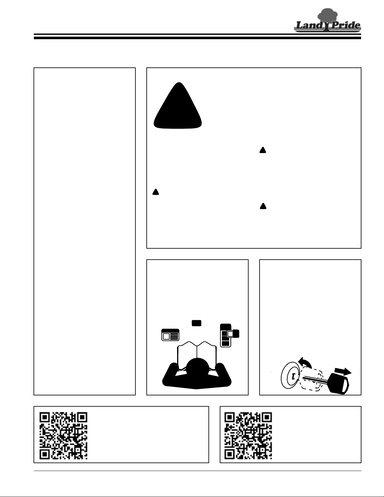
Parts Manual QR Locator
The QR (Quick Reference) code on the
cover and to the left will take you to the
Parts Manual for this equipment.
Download the appropriate App on your
smart phone, open the App, point your
phone on the QR code and take a picture.
Dealer QR Locator
The QR code on the left will
link you to available dealers
for Land Pride products.
Refer to Parts Manual QR
Locator on this page for
detailed instructions.
!
Be Aware of
Signal Words
A Signal word designates a degree or
level of hazard seriousness. The
signal words are:
Indicates an imminently hazardous
situation which, if not avoided, will
result in death or serious injury. This
signal word is limited to the most
extreme situations, typically for
machine components that, for
functional purposes, cannot be
guarded.
!
DANGER
Indicates a potentially hazardous
situation which, if not avoided, could
result in death or serious injury, and
includes hazards that are exposed
when guards are removed. It may also
be used to alert against unsafe
practices.
Indicates a potentially hazardous
situation which, if not avoided, may
result in minor or moderate injury. It
may also be used to alert against
unsafe practices.
!
WARNING
!
CAUTION
Safety at All Times
Thoroughly read and understand
the instructions given in this
manual before operation. Refer to
the “Safety Label” section, read all
instructions noted on them.
Do not allow anyone to operate
this equipment who has not fully
read and comprehended this
manual and who has not been
properly trained in the safe
operation of the equipment.
▲ The operator must not use drugs
or alcohol as they can change the
alertness or coordination of that
person while operating equipment.
The operator should, if taking over-
the-counter drugs, seek medical
advice on whether he/she can
safely operate the equipment.
▲ Operator should be familiar with all
functions of the tractor and
attachments, and be able to
handle emergencies quickly.
▲ Make sure all guards and shields
are in place and secured before
operating implement.
▲ Keep all bystanders away from
equipment and work area.
▲ Operator must start tractor and
operate controls from the driver’s
seat only. Never from the ground.
▲ Do not leave tractor or implement
unattended with engine running.
▲ Dismounting from a moving tractor
can cause serious injury or death.
▲ Do not allow anyone to stand
between tractor and implement
while backing up to implement.
▲ Keep hands, feet, and clothing
away from power-driven parts.
▲ Watch out for fences, trees, rocks,
wires, etc., while operating and
transporting implement.
▲ Turning tractor too tight may cause
hitched machinery to ride up on
wheels. This could result in injury
or equipment damage.
Look For The Safety Alert Symbol
The SAFETY ALERT SYMBOL indicates there is a
potential hazard to personal safety involved and extra
safety precaution must be taken. When you see this
symbol, be alert and carefully read the message that
follows it. In addition to design and configuration of
equipment, hazard control, and accident prevention are
dependent upon the awareness, concern, prudence, and
proper training of personnel involved in the operation,
transport, maintenance, and storage of equipment.
For Your Protection
▲ Thoroughly read and understand
the “Safety Label” section, read
all instructions noted on them.
Tractor Shutdown & Storage
▲ If engaged, disengage PTO.
▲ Lower attached implement to
ground, put tractor in park or set
park brake, turn off engine, and
remove switch key to prevent
unauthorized starting.
▲ Wait for all components to come to
a complete stop before leaving the
operator’s seat.
▲ Detach and store implement in an
area where children normally do
not play. Secure implement using
blocks and supports.
OFF
R
E
M
O
V
E

2
Important Safety Information
RCF2760 and RCF2772 Rotary Cutters 326-460M
12/15/15
Table of Contents
These are common practices that may or may not be applicable to the products described in
this manual.
Use A Safety Chain
▲ A safety chain will help control
drawn machinery should it
separate from the tractor drawbar.
▲ Use a chain with the strength
rating equal to or greater than the
gross weight of the towed
machinery.
▲ Attach the chain to the tractor
drawbar support or other specified
anchor location. Allow only
enough slack in the chain to
permit turning.
▲ Do not use safety chain for towing.
Use Safety
Lights and Devices
▲ Slow moving tractors,
self-propelled equipment, and
towed implements can create a
hazard when driven on public
roads. They are difficult to see,
especially at night.
▲ Flashing warning lights and turn
signals are recommended
whenever driving on public roads.
▲ Maximum transport speed for an
attached implement is 20 mph. DO
NOT EXCEED. Never travel at a
speed which does not allow
adequate control of steering and
stopping. Some rough terrains
require a slower speed.
▲ As a guideline, use the following
maximum speed weight ratios for
an attached implement:
20 mph when weight of attached
implement is less than or equal to
the weight of machine towing the
implement.
10 mph when weight of attached
implement exceeds weight of
machine towing implement but
not more than double the weight.
▲ IMPORTANT: Do not tow a load
that is more than double the weight
of the machine towing the load.
Transport
Machinery Safely
▲ Comply with state and local laws.
▲ Use towing vehicle and trailer of
adequate size and capacity.
▲ Secure equipment towed on a
trailer with tie downs and chains.
▲ Sudden braking can cause a trailer
to swerve and upset. Reduce
speed if trailer is not equipped with
brakes.
▲ Avoid contact with any over head
utility lines or electrically charged
conductors.
▲ Engage park brake when stopped
on an incline.
Practice Safe Maintenance
▲ Understand procedure before doing
work. Use proper tools and
equipment, refer to Operator’s
Manual for additional information.
▲ Work in a clean dry area.
▲ Lower attached implement to the
ground, put tractor in park, turn off
engine, and remove key before
performing maintenance.
▲ Allow implement to cool before
working on it.
▲ Disconnect battery ground cable (-)
before servicing or adjusting
electrical systems or before welding
on implement.
▲ Do not grease or oil implement
while it is in operation.
▲ Inspect all parts. Make certain
parts are in good condition &
installed properly.
▲ Replace parts on this machine with
genuine Land Pride parts only. Do
not alter this machine in a way
which will adversely affect its
performance.
▲ Remove buildup of grease, oil, or
debris.
▲ Remove all tools and unused parts
from implement before operation.

3
Important Safety Information
12/15/15
RCF2760 and RCF2772 Rotary Cutters 326-460M
Table of Contents
These are common practices that may or may not be applicable to the products described in
this manual.
Prepare for Emergencies
▲ Be prepared if a fire starts.
▲ Keep a first aid kit and fire
extinguisher handy.
▲ Keep emergency numbers for
doctor, ambulance, hospital, and
fire department near phone.
Avoid High
Pressure Fluids Hazard
▲ Escaping fluid under pressure can
penetrate the skin causing serious
injury.
▲ Avoid the hazard by relieving
pressure before disconnecting
hydraulic lines or performing work
on the system.
▲ Make sure all hydraulic fluid
connections are tight and all
hydraulic hoses and lines are in
good condition before applying
pressure to the system.
▲ Use a piece of paper or
cardboard, NOT BODY PARTS, to
check for suspected leaks.
▲ Wear protective gloves and safety
glasses or goggles when working
with hydraulic systems.
▲ DO NOT DELAY. If an accident
occurs, see a doctor familiar with
this type of injury immediately. Any
fluid injected into the skin or eyes
must be treated within
a few hours or
gangrene may
result.
911
Keep Riders Off
Machinery
▲ Never carry riders or use
machinery as a person lift.
▲ Riders obstruct operator’s view.
▲ Riders could be struck by foreign
objects or thrown from the
machine.
▲ Never allow children to operate
equipment.
Wear
Protective Equipment
▲ Wear protective clothing and
equipment appropriate for the job
such as safety shoes, safety
glasses, hard hat, and ear plugs.
▲ Clothing should fit snug without
fringes and pull strings to avoid
entanglement with moving parts.
▲ Prolonged exposure to loud noise
can cause hearing impairment or
hearing loss. Wear suitable
hearing protection such as
earmuffs or earplugs.
▲ Operating equipment safely
requires the operator’s full
attention. Avoid wearing radio
headphones while operating
machinery.
Use Seat Belt and ROPS
▲ Operate only tractors equipped
with a Roll-Over Protective
Structure (ROPS) and seat belt.
▲ Keep folding ROPS in the “locked
up” position at all times.
▲ Fasten seat belt snugly and
securely to help protect against
serious injury or death from falling
and machine overturn.
▲ Wear protective equipment such
as a hard hat, safety shoes, safety
glasses, and ear plugs.
Tire Safety
▲ Tire changing can be dangerous
and should be performed by
trained personnel using the
correct tools and equipment.
▲ When inflating tires, use a clip-on
chuck and extension hose long
enough to allow you to stand to
one side and NOT in front of or
over the tire assembly. Use a
safety cage if available.
▲ When removing and installing
wheels, use wheel handling
equipment adequate for the
weight involved.
4
Important Safety Information
RCF2760 and RCF2772 Rotary Cutters 326-460M
12/15/15
Table of Contents
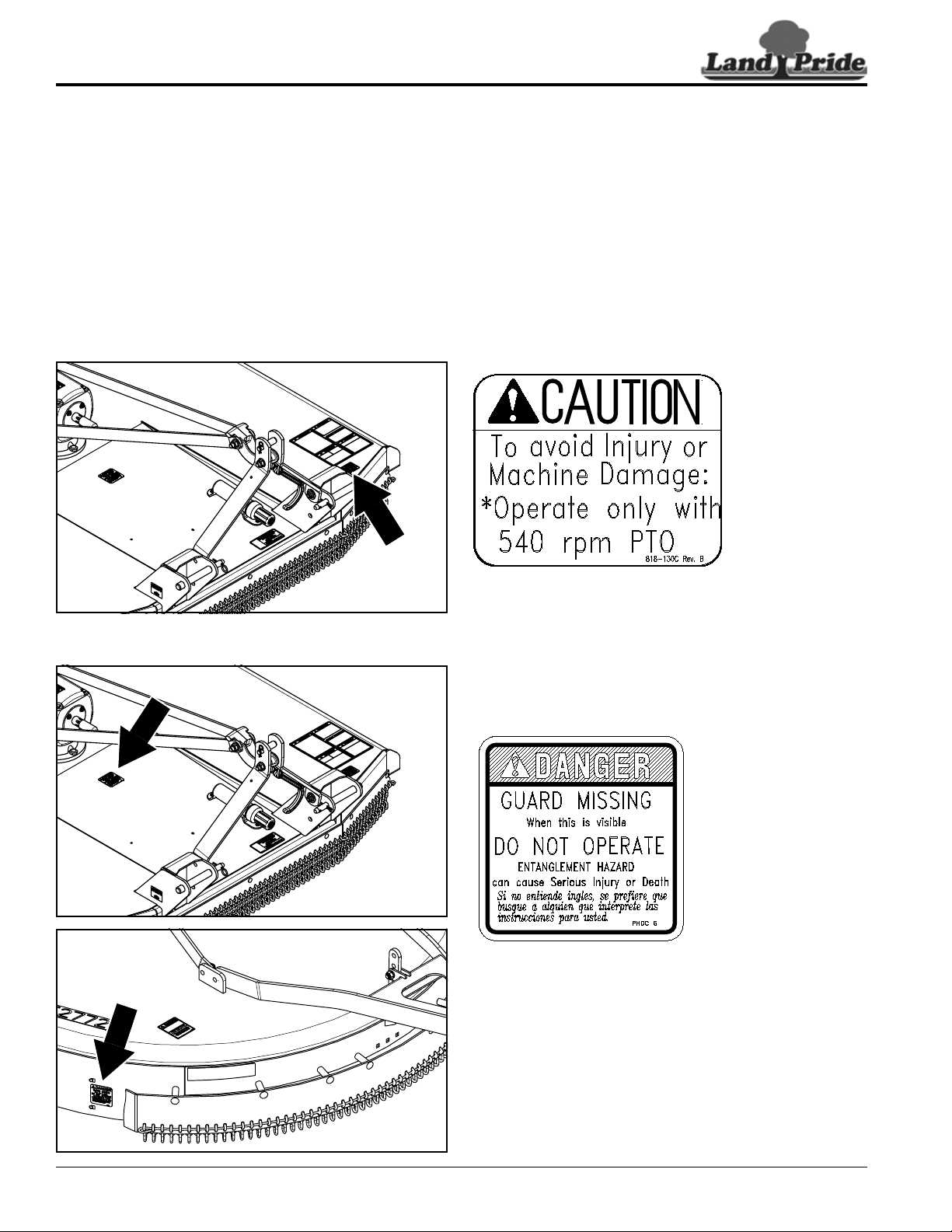
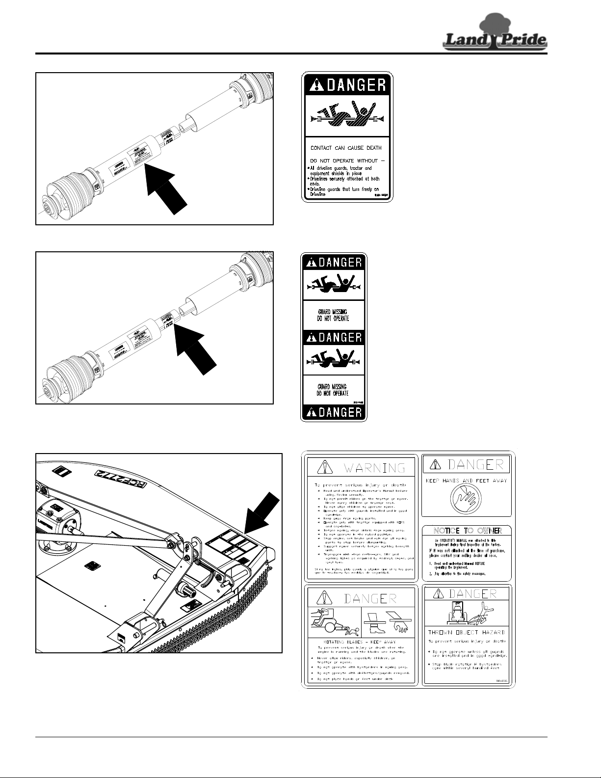
Safety Labels
Your Rotary Cutter comes equipped with all safety labels in
place. They were designed to help you safely operate your
implement. Read and follow their directions.
1. Keep all safety labels clean and legible.
2. Refer to this section for proper label placement. Replace
all damaged or missing labels. Order new labels from your
nearest Land Pride dealer. To find your nearest dealer,
visit our dealer locator at www.landpride.com.
3. Some new equipment installed during repair requires
safety labels to be affixed to the replaced component as
818-130C
Caution: 540 RPM
818-543C
Danger: Guard Missing
(2 places)
30947
30947
30948
specified by Land Pride. When ordering new components
make sure the correct safety labels are included in the
request.
4. Refer to this section for proper label placement.
To install new labels:
a. Clean surface area where label is to be placed.
b. Spray soapy water onto the cleaned area.
c. Peel backing from label and press label firmly onto the
surface.
d. Squeeze out air bubbles with edge of a credit card or
with a similar type of straight edge.
5
Important Safety Information
12/15/15
RCF2760 and RCF2772 Rotary Cutters 326-460M
Table of Contents
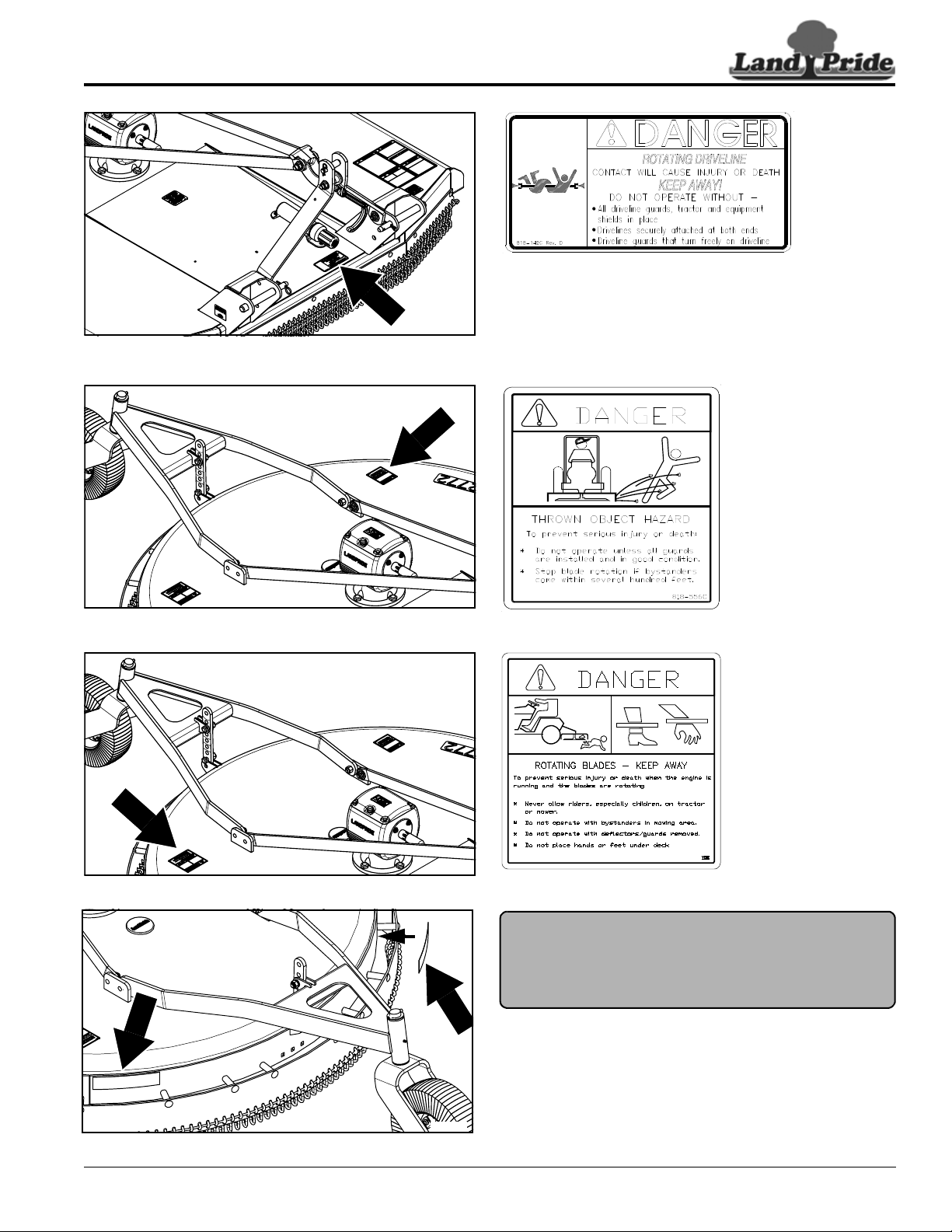
818-556C
Danger: Thrown Object
818-564C
Danger: Rotating Blades
818-142C
Danger: Rotating Driveline
30947
838-614C
Red Reflector
(2 places)
30948
30947
30947
6
Important Safety Information
RCF2760 and RCF2772 Rotary Cutters 326-460M
12/15/15
Table of Contents
818-552C
Danger: Rotating Driveline
ROTATING DRIVELINE
KEEP AWAY!
818-540C
Danger: Guard Missing
818-830C
30947
24597
24597
7
Introduction
12/15/15
RCF2760 and RCF2772 Rotary Cutters 326-460M
Table of Contents
Introduction
Owner Assistance
The Online Warranty Registration should be completed
by the dealer at the time of purchase. This information is
necessary to provide you with quality customer service.
The parts on your Rotary Cutter have been specially
designed by Land Pride and should only be replaced with
genuine Land Pride parts. Contact a Land Pride dealer if
customer service or repair parts are required. Your Land
Pride dealer has trained personnel, repair parts, and
equipment needed to service the implement.
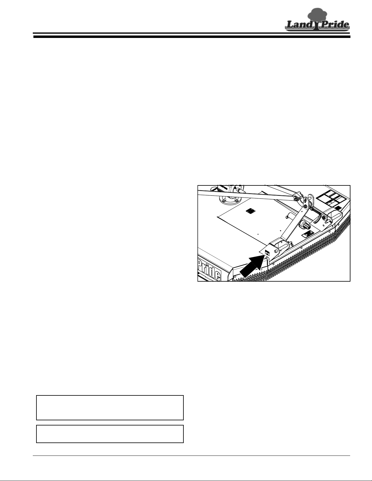
Serial Number
Model No. _____________Serial No. ______________
For quick reference and prompt service, record model
number and serial number in the spaces provided above
and again on warranty page 33. Always provide model
number and serial number when ordering parts and in all
correspondences with your Land Pride dealer. Refer to
Figure 1 for location of your serial number.
Figure 1
Further Assistance
Your dealer wants you to be satisfied with your new
Rotary Cutter. If for any reason you do not understand
any part of this manual or are not satisfied with the
service received, the following actions are suggested:
1. Discuss the matter with your dealership service
manager making sure that person is aware of any
problems you may have and has had the opportunity
to assist you.
2. If you are still not satisfied, seek out the owner or
general manager of the dealership, explain the
problem, and request assistance.
3. For further assistance write to:
Land Pride Service Department
1525 East North Street
P.O. Box 5060
Salina, Ks. 67402-5060
E-mail address
lpservicedept@landpride.com
30947
Land Pride welcomes you to the growing family of new
product owners.
This Rotary Cutter has been designed with care and built
by skilled workers using quality materials. Proper
assembly, maintenance, and safe operating practices will
help you get years of satisfactory use from this machine.
Application
The RCF2760 and RCF2772 Series Rotary Cutters are
designed and built by Land Pride to provide excellent
cutting performance on gentle slopes, slightly contoured
right-of-ways, roadsides, pastures, set-aside-acres,
around the farm, and around town. They are compatible
with 35 to 130 horsepower tractors with a category I or II
three-point hitch and 540 RPM PTO speed. The cutters
are Quick Hitch adaptable and equipped with an ASAE
category 4 driveline with 4-plate slip-clutch for protection.
RCF27 Series cutters with 1 1/2" to 12" cutting height
range, can cut through grass, weeds, crops, brush, and
small trees up to 3 inches in diameter with a blade tip
speed of 12,384 FPM for the RCF2760 and 14,861 FPM
for the RCF2772. These units come equipped standard
with a 3/16" thick heavy-duty stump jumper and
replaceable bolt-on skid shoes. Optional shields for the
front are rubber deflector and single chain guard.
Optional shield for the rear is single chain guard.
See “Specifications & Capacities” on page 28 and
“Features & Benefits” on page 30 for additional
information and performance enhancing options.
Using This Manual
•
This Operator’s Manual is designed to help familiarize
the operator with safety, assembly, operation,
adjustments, troubleshooting, and maintenance. Read
this manual and follow the recommendations to help
ensure safe and efficient operation.
• The information contained within this manual was
current at the time of printing. Some parts may change
slightly to assure you of the best performance.
• To order a new Operator’s or Parts Manual, contact
your authorized dealer. Manuals can also be
downloaded, free-of-charge, from our website at
www.landpride.com
Terminology:
“Right” or “Left” as used in this manual is determined by
facing the direction the machine will operate while in use
unless otherwise stated.
Definitions:
IMPORTANT: A special point of information related
to the following topic. Land Pride’s intention is this
information must be read & noted before continuing.
NOTE: A special point of information that the
operator should be aware of before continuing.

8
Section 1: Assembly & Set-up
RCF2760 and RCF2772 Rotary Cutters 326-460M
12/15/15
Table of Contents
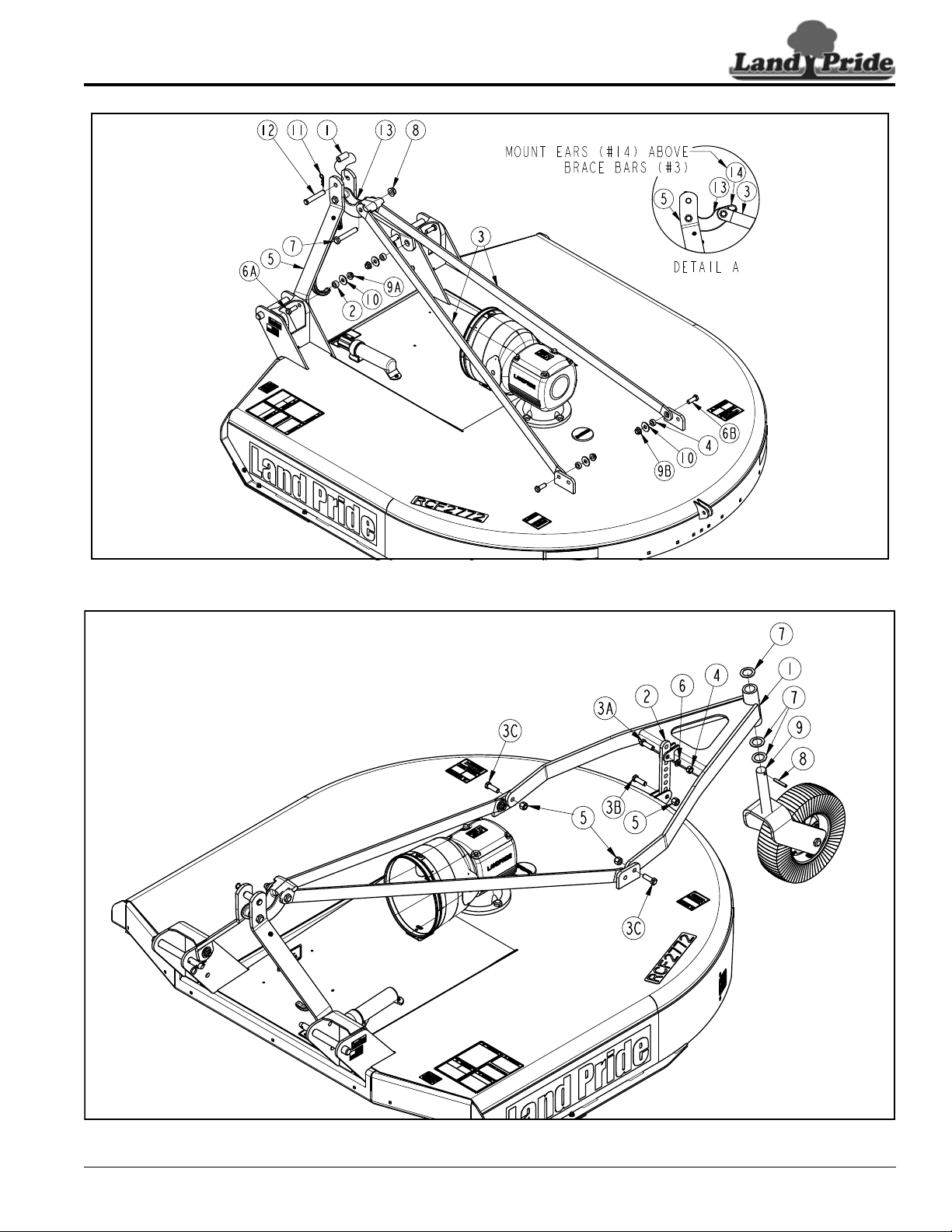
Section 1: Assembly & Set-up
1. The cutter is shipped with 3/4" clevis pin (#12), pivot
tube (#1), and hairpin cotter (#11) assembled to hitch
straps (#5). Pivot tube (#1) should be removed only if
hitching to a Cat. 1 hitch.
2. Bushings (#2) are zip tied to top hitch (#13).
3. Remove hex flange lock nuts (#9A) and flat
washers (#10) from bolt (#6A).
4. Reattach A-frame brace bars (#5) with
5/8"-11 x 1 3/4" hex head bolts (#6A), bushings (#2),
flat washers (#10), and lock nuts (#9A). Tighten lock
nuts (#9A).
5. Attach 1 5/32" diameter holes in rear brace bars (#3)
to inside of rear deck lugs with 5/8"-11 x 1 3/4" GR5
bolts (#6B), 13/32" long bushings (#4), flat washers
(#10), and lock nuts (#9B). Tighten lock nuts (#9B).
6. Rotate A-frame/floating top hitch (#5 & #13) up and
rotate left rear brace (#3) up until holes in rear
braces (#3) align with hole in floating top hitch (#13).
7. Insert 3/4"-10 x 4 1/2" GR5 bolt (#7) into the left rear
brace (#3), floating top hitch (#13), and right rear
brace (#3).
8. Secure bolt with hex flange lock nut (#8). Draw lock
nut (#8) up snug and then back off 1/4 turn.
Tailwheel Assembly
Refer to Figure 1-2:
1. Attach tailwheel gauge arm (#1) to inside of rear deck
lugs with 5/8"-11 x 2" GR5 cap screws (#3C) and hex
nylock nuts (#5). Draw nylock nut (#5) up snug and
then back off 1/4 turn.
2. Install two 2 1/4" OD machine washers (#7) onto
tailwheel spindle (#9).
3. Insert tailwheel spindle into tailwheel pivot tube (#1).
4. Install third machine washer (#7) over tailwheel
spindle and secure with 3/8" x 2 1/2" roll pin (#8).
5. Attach bottom hole of tailwheel adjustment bar (#2) to
deck rear with 5/8"-11 x 2" GR5 cap screw (#3B), and
hex nylock nut (#5). Draw nylock nut up tight, do not
torque tight.
6. Tighten hex nut (#4) until lock washer (#6) is
squeezed flat.
IMPORTANT: See Detail A in Figure 1-1 on page 9.
Floating top hitch (#13) must be installed with
ears (#14) above rear brace bars (#3).
NOTE: After assembly of hitch, push on top of
A-frame assembly (#5). It should rotate backwards
and floating top link (#13) should rotate upwards. If
they are too stiff to rotate, loosen nuts (#8) until
floating top link (#13) rotates freely.
NOTE: Keep adjustment bar (#2) rotated up off the
deck to prevent scratching the paint while driving roll
pin (#8) in with a hammer.
Tractor Requirements
Tractor horsepower and hitch category should be within
the range noted below. Tractors outside the horsepower
range must not be used.
Tractor Horsepower Rating . . . . . . . . . . . 35 to 130 HP
Hitch Category . . . . . . . . . . . . . . . . . . . . . . Cat I & II
PTO Speed. . . . . . . . . . . . . . . . . . . . . . . . . .540 RPM
PTO Shaft Type . . . . . . . . . . . . . . . . . 1 3/8"-6 Spline
!
WARNING
Ballast weights may need to be added to your tractor to
maintain steering control. Refer to your tractor operator’s
manual to determine proper ballast requirements.
Torque Requirements
Refer to “Torque Values Chart for Common Bolt Sizes”
on page 32 to determine correct torque values when
tightening hardware. See “Additional Torque Values” at
bottom of chart for exceptions to standard torque values.
Uncrating Instructions
!
WARNING
Always secure cutter with an overhead crane, fork lift, or
other suitable lifting device before removing hardware bags,
shipping components, bands, lag screws, and hitch pins. The
cutter can suddenly fall causing serious injury or death.
1. Secure cutter with a hoist or other lifting device
before removing shipping hardware.
2. Cut shipping straps securing driveline and hitch
straps (#5) to the shipping crate. Remove driveline
from shipping crate and lay gently hitch straps down
onto the shipping crate.
3. 5-pack only: Remove bar at the top connecting this
cutter to other cutters. Be sure to replace the bolts in
the cutter and to tighten it to the correct torque.
4. Remove lag screws securing cutter deck to crate.
5. Using lifting device, remove tension on hitch pins
securing clevis plates to shipping crate.
6. Remove hitch pins from clevis plates and lift cutter
from shipping crate.
7. Gently lower cutter onto the working area. Be careful
not to allow hitch straps (#5) to fall onto the plastic
manual tube.
3-Point Hitch Assembly
Refer to Figure 1-1 on page 9:
NOTE: When lowering cutter onto the working area,
keep hitch straps (#5) from falling onto the manual
tube and breaking the tube.
NOTE: Pivot tube (#1) is used only when
hooking-up to a Cat. ll 3-point hitch.
9
Section 1: Assembly & Set-up
12/15/15
RCF2760 and RCF2772 Rotary Cutters 326-460M
Table of Contents
Hitch Assembly
Figure 1-1
30950
Tail Wheel Assembly
Figure 1-2
30951
Loading...