

Landoll 9630 User Manual
Model 9630
Field Cultivator
Operator’ s Manual
LANDOLL CORPORATION
1900 North Street
Marysville, Kansas 66508
(785) 562-5381
800-428-5655 ~ WWW.LANDOLL.COM
F-632-0114 01/2014


1 Introduction
Understanding Safety Statements . . . . . . . . . . . . . . . . . . . . . . . . . . . . . . . . . . . . . . . . . . . . . . . . 1-2
2 Standard Specifications
3 Assembly Instructions
Frame and Hitch Assembly . . . . . . . . . . . . . . . . . . . . . . . . . . . . . . . . . . . . . . . . . . . . . . . . . . . . . . 3-3
Center Frame Tire Installation . . . . . . . . . . . . . . . . . . . . . . . . . . . . . . . . . . . . . . . . . . . . . . . . . . . 3-3
Leveling Linkage Assembly . . . . . . . . . . . . . . . . . . . . . . . . . . . . . . . . . . . . . . . . . . . . . . . . . . . . . 3-5
Wing Frames . . . . . . . . . . . . . . . . . . . . . . . . . . . . . . . . . . . . . . . . . . . . . . . . . . . . . . . . . . . . . . . . . . 3-7
Wing Lift Tire Installation . . . . . . . . . . . . . . . . . . . . . . . . . . . . . . . . . . . . . . . . . . . . . . . . . . . . . . . 3-7
Front Gauge Wheel Installation . . . . . . . . . . . . . . . . . . . . . . . . . . . . . . . . . . . . . . . . . . . . . . . . . . 3-7
Lighting and SMV Bracket Installation (Prior to August, 2013) . . . . . . . . . . . . . . . . . . . . . . . . . 3-9
Table of Contents
LED Light and SMV Bracket Installation (After August, 2013) . . . . . . . . . . . . . . . . . . . . . . . . . 3-11
Hydraulic Installation . . . . . . . . . . . . . . . . . . . . . . . . . . . . . . . . . . . . . . . . . . . . . . . . . . . . . . . . . . 3-19
Shank Installation . . . . . . . . . . . . . . . . . . . . . . . . . . . . . . . . . . . . . . . . . . . . . . . . . . . . . . . . . . . . 3-21
4 Row Coil Tine Harrow Installation . . . . . . . . . . . . . . . . . . . . . . . . . . . . . . . . . . . . . . . . . . . . . . 3-23
5 Row Spike Harrow Installation . . . . . . . . . . . . . . . . . . . . . . . . . . . . . . . . . . . . . . . . . . . . . . . . . 3-25
3 Row Spike and Reel Harrow Installation . . . . . . . . . . . . . . . . . . . . . . . . . . . . . . . . . . . . . . . . . 3-27
3 Row Coil Tine and Reel Harrow Installation . . . . . . . . . . . . . . . . . . . . . . . . . . . . . . . . . . . . . . 3-29
Rear Tow Hitch (Option) . . . . . . . . . . . . . . . . . . . . . . . . . . . . . . . . . . . . . . . . . . . . . . . . . . . . . . . 3-31
4 Operation and Maintenance
Hydraulic Lift System . . . . . . . . . . . . . . . . . . . . . . . . . . . . . . . . . . . . . . . . . . . . . . . . . . . . . . . . . . 4-2
Hydraulic Fold System . . . . . . . . . . . . . . . . . . . . . . . . . . . . . . . . . . . . . . . . . . . . . . . . . . . . . . . . . 4-3
Transporting . . . . . . . . . . . . . . . . . . . . . . . . . . . . . . . . . . . . . . . . . . . . . . . . . . . . . . . . . . . . . . . . . . 4-5
Tractor Preparation . . . . . . . . . . . . . . . . . . . . . . . . . . . . . . . . . . . . . . . . . . . . . . . . . . . . . . . . . . . . 4-6
Prior to Transport . . . . . . . . . . . . . . . . . . . . . . . . . . . . . . . . . . . . . . . . . . . . . . . . . . . . . . . . . . . . . . 4-6
Leveling (Front-to-Rear) . . . . . . . . . . . . . . . . . . . . . . . . . . . . . . . . . . . . . . . . . . . . . . . . . . . . . . . . 4-6
Leveling (Side to Side) . . . . . . . . . . . . . . . . . . . . . . . . . . . . . . . . . . . . . . . . . . . . . . . . . . . . . . . . . . 4-7
Gauge Wheels . . . . . . . . . . . . . . . . . . . . . . . . . . . . . . . . . . . . . . . . . . . . . . . . . . . . . . . . . . . . . . . . 4-7
Depth Stop Adjustment . . . . . . . . . . . . . . . . . . . . . . . . . . . . . . . . . . . . . . . . . . . . . . . . . . . . . . . . . 4-8
F-632-0114 Edition i

General Operation . . . . . . . . . . . . . . . . . . . . . . . . . . . . . . . . . . . . . . . . . . . . . . . . . . . . . . . . . . . . . 4-8
LED Light Operation . . . . . . . . . . . . . . . . . . . . . . . . . . . . . . . . . . . . . . . . . . . . . . . . . . . . . . . . . . . . 4-8
Spring Shank . . . . . . . . . . . . . . . . . . . . . . . . . . . . . . . . . . . . . . . . . . . . . . . . . . . . . . . . . . . . . . . . . 4-9
Sweeps . . . . . . . . . . . . . . . . . . . . . . . . . . . . . . . . . . . . . . . . . . . . . . . . . . . . . . . . . . . . . . . . . . . . . . 4-9
Wheel Bearing Maintenance . . . . . . . . . . . . . . . . . . . . . . . . . . . . . . . . . . . . . . . . . . . . . . . . . . . . . 4-9
Lubrication . . . . . . . . . . . . . . . . . . . . . . . . . . . . . . . . . . . . . . . . . . . . . . . . . . . . . . . . . . . . . . . . . . 4-10
4 Row Coil Tine Harrow . . . . . . . . . . . . . . . . . . . . . . . . . . . . . . . . . . . . . . . . . . . . . . . . . . . . . . . . 4-11
5 Row Spike Harrows . . . . . . . . . . . . . . . . . . . . . . . . . . . . . . . . . . . . . . . . . . . . . . . . . . . . . . . . . . 4-13
3 Row Spike and Reel Harrow . . . . . . . . . . . . . . . . . . . . . . . . . . . . . . . . . . . . . . . . . . . . . . . . . . . 4-15
3 Row Coil Tine and Reel Harrow . . . . . . . . . . . . . . . . . . . . . . . . . . . . . . . . . . . . . . . . . . . . . . . . 4-17
Storage . . . . . . . . . . . . . . . . . . . . . . . . . . . . . . . . . . . . . . . . . . . . . . . . . . . . . . . . . . . . . . . . . . . . . 4-17
5 Troubleshooting Guide
ii F-632-0114 Edition

Chapter 1
Introduction
The Landoll Model 9630 Field Cultivator is a quality product designed to give years of trouble free performance. By
following each section of this manual, your system will perform as designed for you and your operation
CHAPTER 1 gives basic instructions on the use of this manual.
CHAPTER 2 gives product specifications. These specifications supply lengths and measures for your
equipment. A S tandard Bolt Torque Table is provided to give guidelines for bolt to rques to
be used when servicing this product.
CHAPTER 3 contains assembly instructions for your Model 9630 Field Cultivator. When these
procedures are correctly followed, your equipment should provide you years of
trouble-free operation and service.
CHAPTER 4 instructs how to operate your equipment before using it, and describes adjustments
needed. It also gives practical advice for the care and maintenance of your Landoll
equipment. Drawings in this section locate adjustment points on the equipment.
NOTE: IF THE EQUIPMENT IS IMPROPERLY ASSEMBLED OR MAINTAINED, THE
WARRANTY IS VOID. IF YOU HAVE ANY QUESTIONS CONTACT:
LANDOLL CORPORATION
1900 NORTH STREET
MARYSVILLE, KANSAS 66508
or phone:
(785) 562-5381 or
(800) 428-5655
or FAX:
(888) 527-3909
CHAPTER 5 is a troubleshooting guide to aid in diagnosing and solving problems with the equipment.
PARTS LIST is a separate manual showing the various assemblies, subassemblies, and systems.
Refer to that manual when ordering Landoll replacement parts. Order parts from your
Landoll dealer.
WARRANTY The Warranty Registration form is included with the product documents. Fill it out and
mail it within 15 days of purchase.
NOTE: IMPROPER ASSEMBLY, MODIFICATION, OR MAINTENANCE OF YOUR
LANDOLL MACHINE CAN VOID YOUR WARRANTY.
COMMENTS Address comments or questions regarding this publication to:
LANDOLL CORPORATION
1900 NORTH STREET
MARYSVILLE, KANSAS 66508
ATTENTION: PUBLICATIONS -DEPT. 55
1-1
INTRODUCTION
DANGER
WARNING
CAUTION
NOTE
NOTE
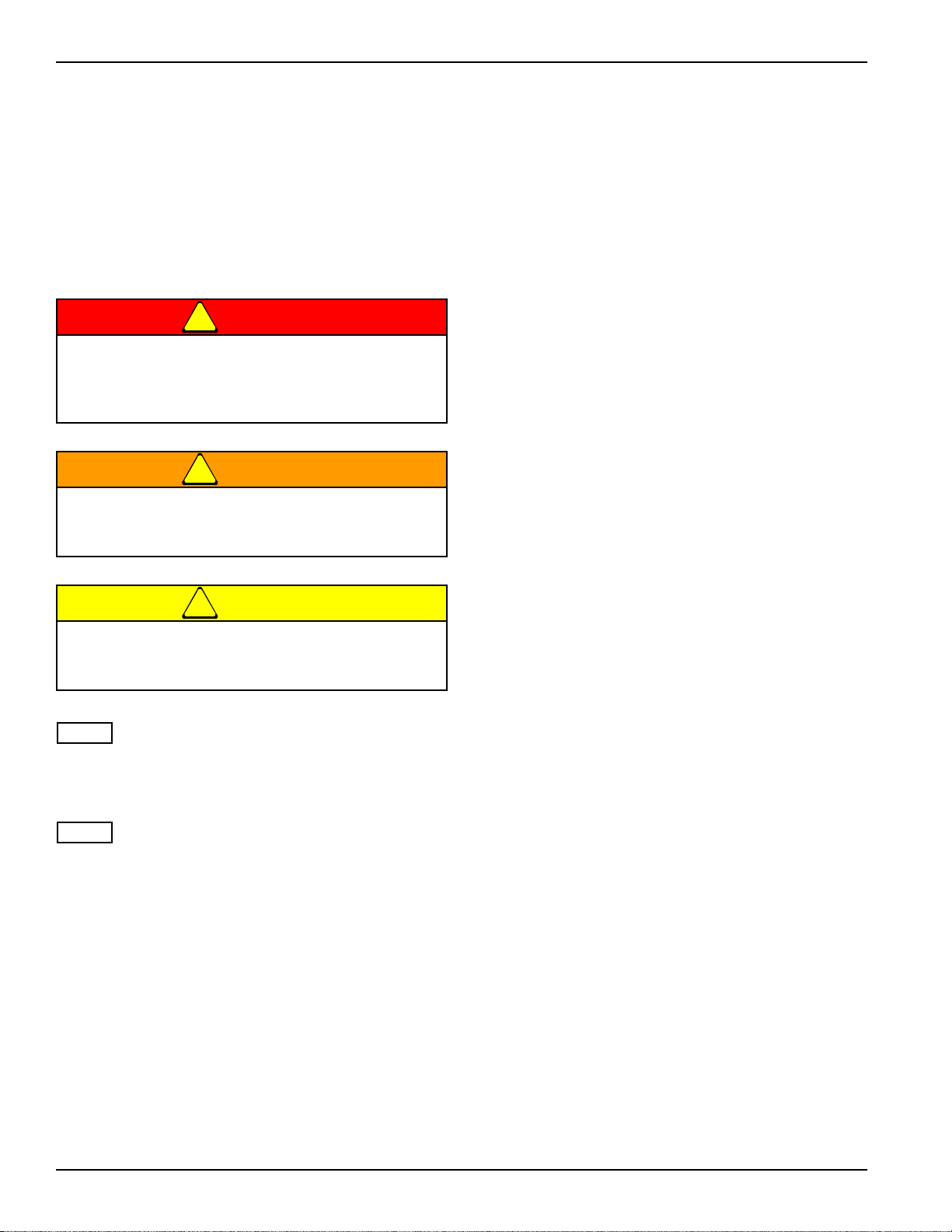
Understanding Safety Statements
You will find various types of safety information on the
following pages and on the machine signs (decals)
attached to the vehicle. This section explains their
meaning.
The Safety Alert Symbol means ATTENTION! YOUR
SAFETY IS INVOLVED!
Danger means a life-threatenin g sit ua ti on ex is ts.
Death can occur if safety measures or
instructions on this label are not properly
followed.
Warning means serious injury or death can occur
if safety measures or instructions on this label
are not properly followed.
Caution means serious equipment or other
property damage can occur if instruction s on this
label are not properly followed.
Means that failure to follow these instructions could
cause damage to the equipment or cause it to operate
improperly.
Make sure you read and understand the informatio n
contained in this manual and on the machine signs
(decals) before you attempt to operate or maintain this
vehicle.
The safety statements contai ned in this manual relate to
the operation of the Model 9630 Field Cultivator.
1-2 F-632-0114 Edition
Chapter 2
Standard Specifications
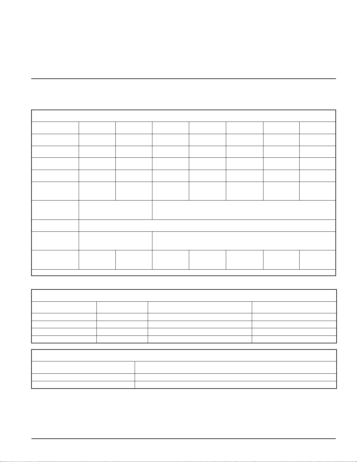
9630 Field Cultivator
Model No. 9630-20 9630-24 9630-28 9630-30NC 9630-30 9630-32 9630-34
Working Width
Tran sport Width
Tran sport Height
No. Of Shanks
Shanks per
Section
Tire Size And
Ply
Spindle Size
Wheel Bolt
Pattern
Estimated
Weight
Specifications Are Subject To Change Without Prior Notification.
20’-6” 24’-6” 28’-6” 30’-6” 30’-6” 32’-6” 34’-6”
16’-0” 15’-6” 15’-1” 15’-1” 17’-4” 17’-4” 17’-4”
9’-3” 1 1’-1” 13’-0” 13’-10” 13’-0” 13’-10” 14’-10”
41 49 57 61 61 65 69
9-23-9 13-23-13 17-23-17 19-23-19 17-27-17 19-27-19 21-27-21
(4) 12.5L x 15, 12 ply
(4) 11L x 15, 12 ply Tires
2-1/4” Spindle
6 Bolt Wheels (Center
Frame and Wings)
N/AN/AN/AN/AN/A N/A
(4) 12.5L x 15 HD (Center Frame)
(4) 11L x 15, 12 ply Tires (Wings
8 Bolt Wheels (Center Frame) and
6 Bolt Wheels (Wings)
Tire Inflation
Tire Size Tire Manufacturer Ply/Load Rating Inflation Pressure (Psi) (Max.)
12.5L - 15 FI Carlisle Load Range F/4680 lbs. @ 55 mph 90 psi
12.5L - 15, 12 ply Carlisle 12 Ply/3,860 lbs. @ 30 mph 52 psi
11L x 15, 12 ply Carlisle 12 Ply/ 3,200 lbs. @ 30 mph 52 psi
20.5 x 8.0-10 Load Range D/ 1,320 lb. 70 psi
RECOMMENDED TORQUE SPECIFICATION FOR LUG BOLTS AND NUTS
BOLT SIZE TORQUE (FT. LBS.)
9/16-18 (Heavy Duty Disc) 80 - 90 ft. lbs
5/8-18 (Heavy Duty Disc) 85 - 100 ft. lbs
2-1
STANDARD SPECIFICATIONS
LANDOLL CORPORATION
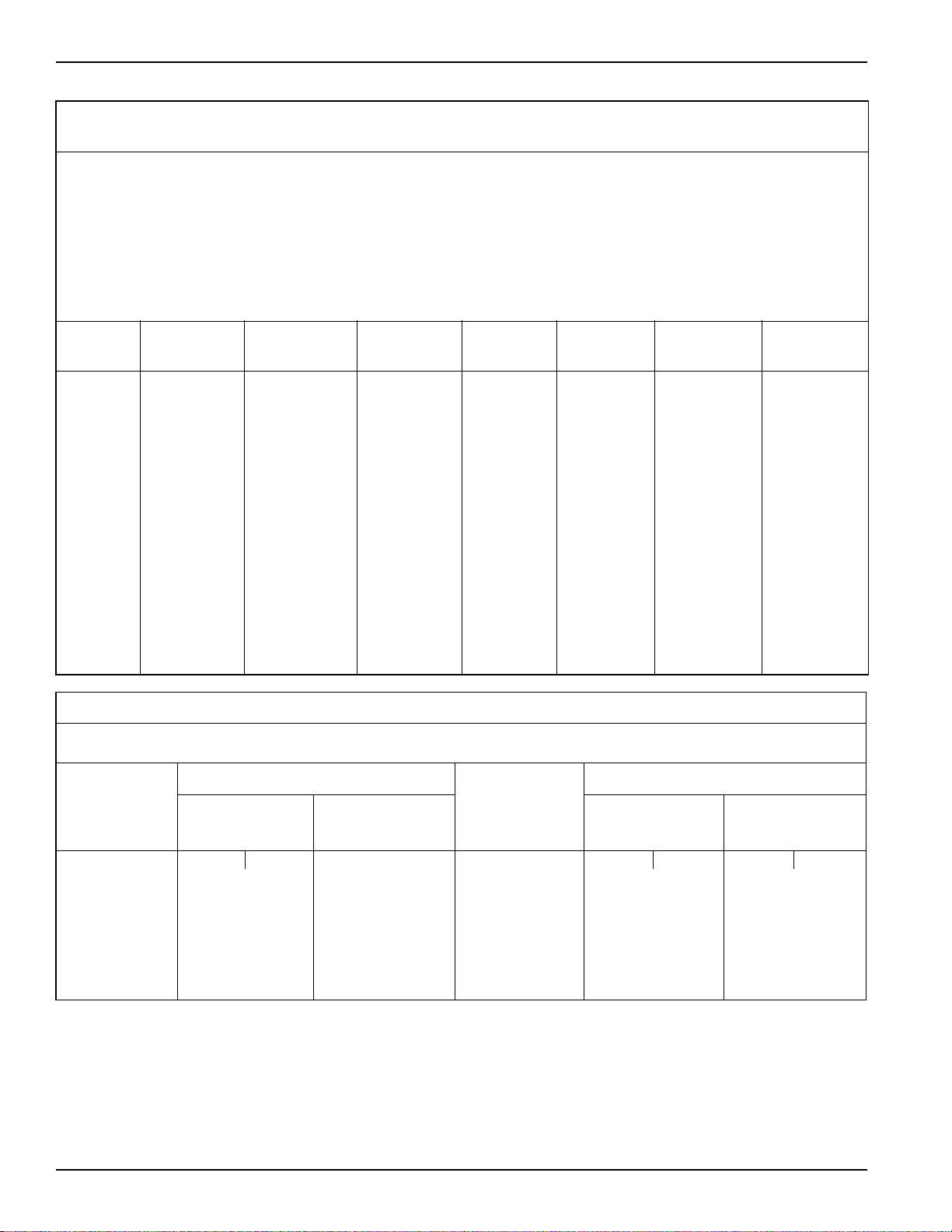
GENERAL TORQUE SPECIFICATIONS (REV. 4/97)
THIS CHART PROVIDES TIGHTENING TORQUES FOR GENERAL PURPOSE APPLICATIONS WHEN SPECIAL TORQUES ARE NOT SPECIFIED ON PROCESS
OR DRAWING.
ASSEMBLY TORQUES APPLY TO PLATED NUTS AND CAPSCREWS ASSEMBLED WITHOUT SUPPLEMENTAL LUBRICATIO N (AS RECEIVED CONDITION).
THEY DO NOT APPLY IF SPECIAL GRAPHITE MOLY-DISULFIDE OR OTHER EXTREME PRESSURE LUBRICANTS ARE USED.
WHEN FASTENERS ARE DRY (SOLVENT CLEANED), ADD 33% TO AS RECEIVED CONDITION TORQUE.
BOLT HEAD IDENTIFICATION MARKS INDICATE GRADE AND MAY VARY FROM MANUFACTURER TO MANUFACTURER.
THICK NUTS MUST BE USED ON GRADE 8 CAPSCREWS.
USE VALUE IN [ ] IF USING PREVAILING TORQUE NUTS.
TORQUE IS SPECIFIED IN FOOT POUNDS
UNC
Size
SAE Grade2SAE Grade5SAE Grade
8
UNF
Size
SAE Grade 2SAE Grade5SAE Grade
8
1/4-20 4 [5] 6 [7] 9 [11] 1/4-28 5 [6] 7 [9] 10 [12]
5/16-18 8 [10] 13 [16] 18 [22] 5/16-24 9 [11] 14 [17] 20 [25]
3/8-16 15 [19] 23 [29] 35 [43] 3/8-24 17 [21] 25 [31] 35 [44]
7/16-14 24 [30] 35 [43] 55 [62] 7/16-20 27 [34] 40 [50] 60 [75]
1/2-13 35 [43] 55 [62] 80 [100] 1/2-20 40 [50] 65 [81] 90 [112]
9/16-12 55 [62] 80 [100] 110 [137] 9/16-18 60 [75] 90 [112] 130 [162]
5/8-11 75 [94] 110 [137] 170 [212] 5/8-18 85 [106] 130 [162] 180 [225]
3/4-10 130 [162] 200 [250] 280 [350] 3/4-16 150 [188] 220 [275] 320 [400]
7/8-9 125 [156] 320 [400] 460 [575] 7/8-14 140 [175] 360 [450] 500 [625]
1-8 190 [237] 408 [506] 680 [850] 1-14 210 [263] 540 [675] 760 [950]
1-1/8-7 270 [337] 600 [750] 960 [1200] 1-1/8-12 300 [375] 660 [825] 1080 [1350]
1-1/4-7 380 [475] 840 [1050] 1426 [1782] 1-1/4-12 420 [525] 920 [1150] 1500 [1875]
1-3/8-6 490 [612] 110 [1375] 1780 [2225] 1-3/8-12 560 [700] 1260 [1575] 2010 [2512]
1-1/2-6 650 [812] 1460 [1825] 2360 [2950] 1/1-2-12 730 [912] 1640 [2050] 2660 [3325]
1-3/4-5 736 [920] 1651 [2063] 2678 [3347] 1-3/4-12 920 [1150] 2063 [2579] 3347 [4183]
METRIC
COARSE THREAD METRIC CLASS 10.9 FASTENERS AND CLASS 10.0 NUTS AND THROUGH HARDENED FLAT WASHERS, PHOSPHATE COATED, ROCKWELL
“C” 38-45.
USE VALUE IN [ ] IF USING PREVAILING TORQUE NUTS.
Nominal
Thread
Diameter
mm
Standard Torque Nominal
Newton-
Meters
Foot-
Pounds
Thread
Diameter
mm
Standard Torque
Newton-
Meters
Foot-
Pounds
6 10 [14] 7 [10] 20 385 [450] 290 [335]
7 16 [22] 12 [16] 24 670 [775] 500 [625]
8 23 [32] 17 [24] 27 980 [1105] 730 [825]
10 46 [60] 34 [47] 30 1330 [1470] 990 [1090]
12 80 [101] 60 [75] 33 1790 [1950] 1340 [1450]
14 125 [155] 90 [115] 36 2325 [2515] 1730 [1870]
16 200 [240] 150 [180] 39 3010 [3210] 2240 [2380]
18 275 [330] 205 [245]
Table 2-1: General Torque Specifications
2-2 F-632-0114 Edition

STANDARD SPECIFICATIONS
LANDOLL CORPORATION
HYDRAULIC FITTING TORQUE SPECIFICATIONS
THIS CHART PROVIDES TIGHTENING TORQUES FOR HYDRAULIC FITTING APPLICATIONS WHEN SPECIAL TORQUES ARE NOT SPECIFIED ON PROCESS
OR DRAWING.
ASSEMBLY TORQUES APPLY TO PLATED CARBON STEEL AND STAINLESS STEEL FITTINGS ASSEMBLED WITHOUT SUPPLEMENTAL LUBRICATION (AS
RECEIVED CONDITION). THEY DO NOT APPLY IF SPECIAL GRAPHITE MOLY-DISULFIDE OR OTHER EXTREME PRESSURE LUBRICANTS ARE USED.
BRASS FITTINGS AND ADAPTERS - 65% OF THE TORQUE VALUE FOR STEEL. STAINLESS STEEL, ALUMINUM AND MONEL - THREADS ARE TO BE
LUBRICATED
.
TORQUE IS SPECIFIED IN FOOT POUNDS
Dash Size 37 Degree JIC O-Ring (ORS) O-Ring Boss (ORB)
-4 11-13 15-17 13-15
-5 14-16 — 21-23
-6 20-22 34-36 25-29
-8 43-47 58-62 40-44
-10 55-65 100-110 57.5-62.5
-12 80-90 134-146 75-85
-16 115-125 202-218 109-121
-20 160-180 248-272 213-237
-24 185-215 303-327 238-262
-32 250-290 — 310-340
o
37
JIC, ORS, & ORB (REV. 10/97)
PARKER BRAND FITTINGS
GATES BRAND FITTINGS
Dash Size 37 Degree JIC O-Ring (ORS) O-Ring Boss (ORB)
-4 10-11 10-12 14-16
-5 13-15 — —
-6 17-19 18-20 24-26
-8 34-38 32-40 37-44
-10 50-56 46-56 50-60
-12 70-78 65-80 75-83
-14 — 65-80 —
-16 94-104 92-105 111-125
-20 124-138 125-140 133-152
-24 156-173 150-180 156-184
-32 219-243 — —
AEROQUIP BRAND FITTINGS
Dash Size 37 Degree JIC O-Ring (ORS) O-Ring Boss (ORB)
-4 11-12 10-12 14-16
-5 15-16 — 18-20
-6 18-20 18-20 24-26
-8 38-42 32-35 50-60
-10 57-62 46-50 72-80
-12 79-87 65-70 125-135
-14 — — 160-180
-16 108-113 92-100 200-220
-20 127-133 125-140 210-280
-24 158-167 150-165 270-360
-32 245-258 — —
Table 2-2: Hydraulic Fitting Torque Specifications
2-3
STANDARD SPECIFICATIONS
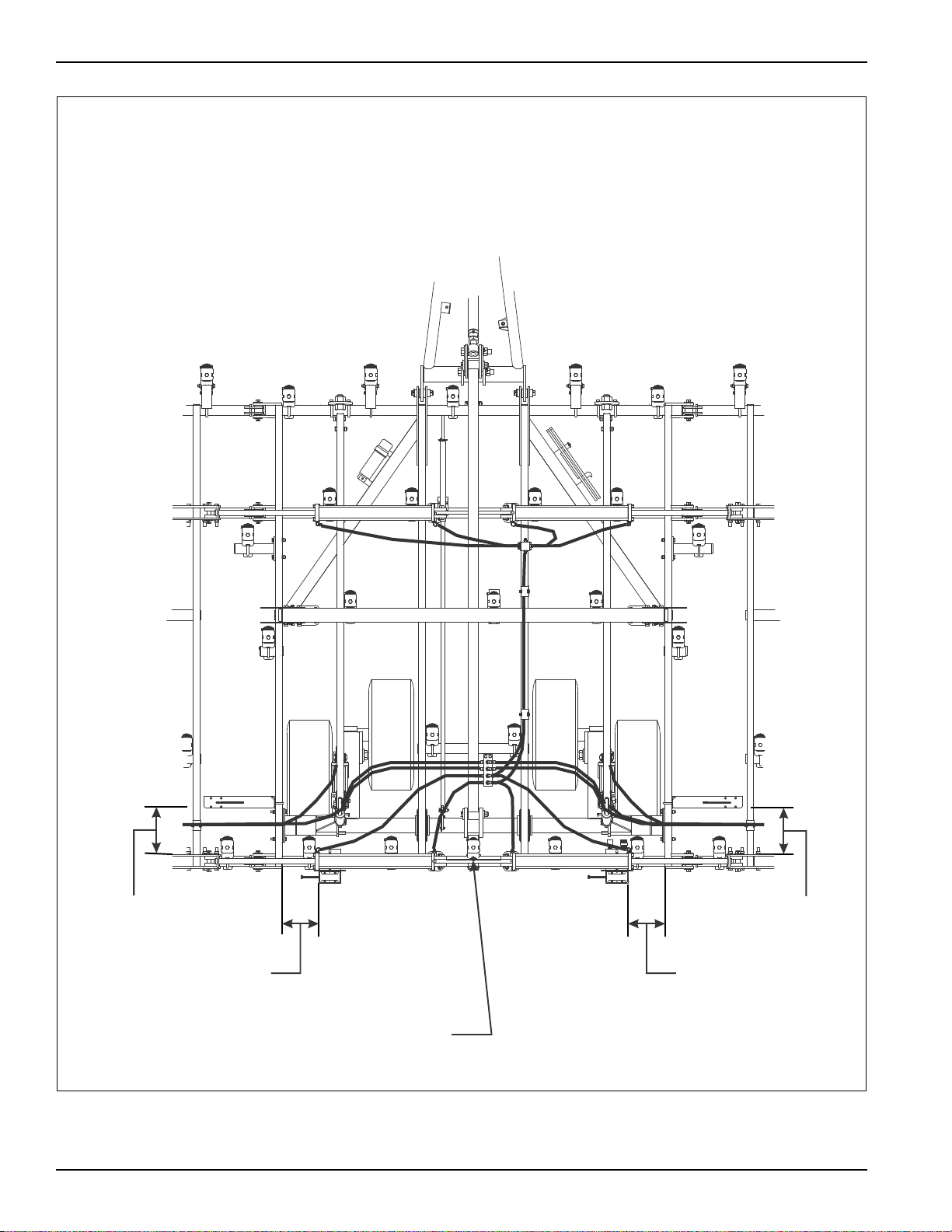
13-1/2
13-1/2
16-3/4
16-3/4
9630-placement
SMV BRACKET (ATTACHES
TO CENTER OF FOLD
CYLINDER REAR MOUNT)
2-4 F-632-0114 Edition
Figure 2-1: Light and SMV Bracket Placement (All Models)
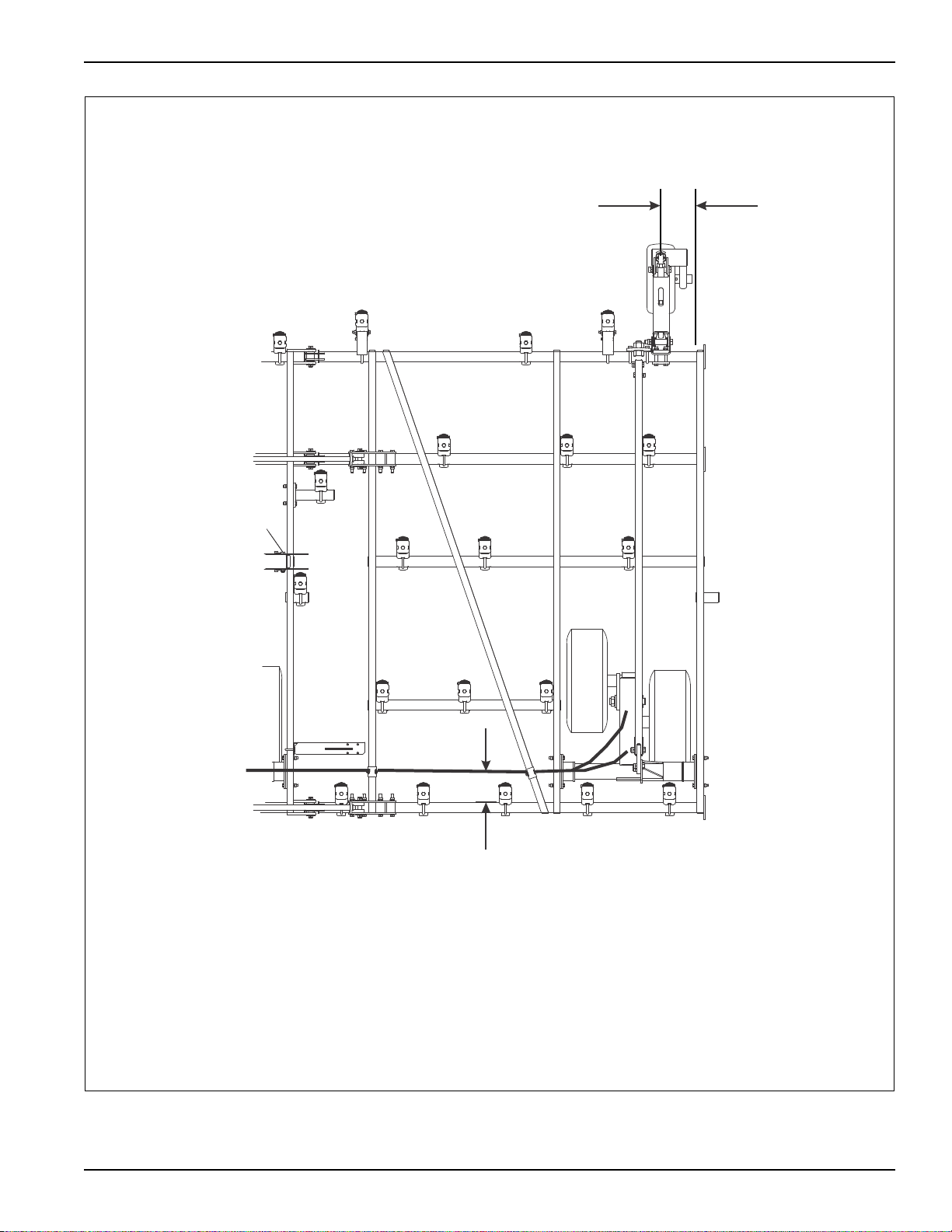
10-1/2
9630-front-gauge-wheel-placement
NOTE: RIGHT SIDE SHOWN - LEFT SIDE FRONT GAUGE
WHEEL PLACEMENT USES SAME DIMENSIONS.
9
STANDARD SPECIFICATIONS
Figure 2-2: Front Gauge Wheel Placement
2-5
STANDARD SPECIFICATIONS
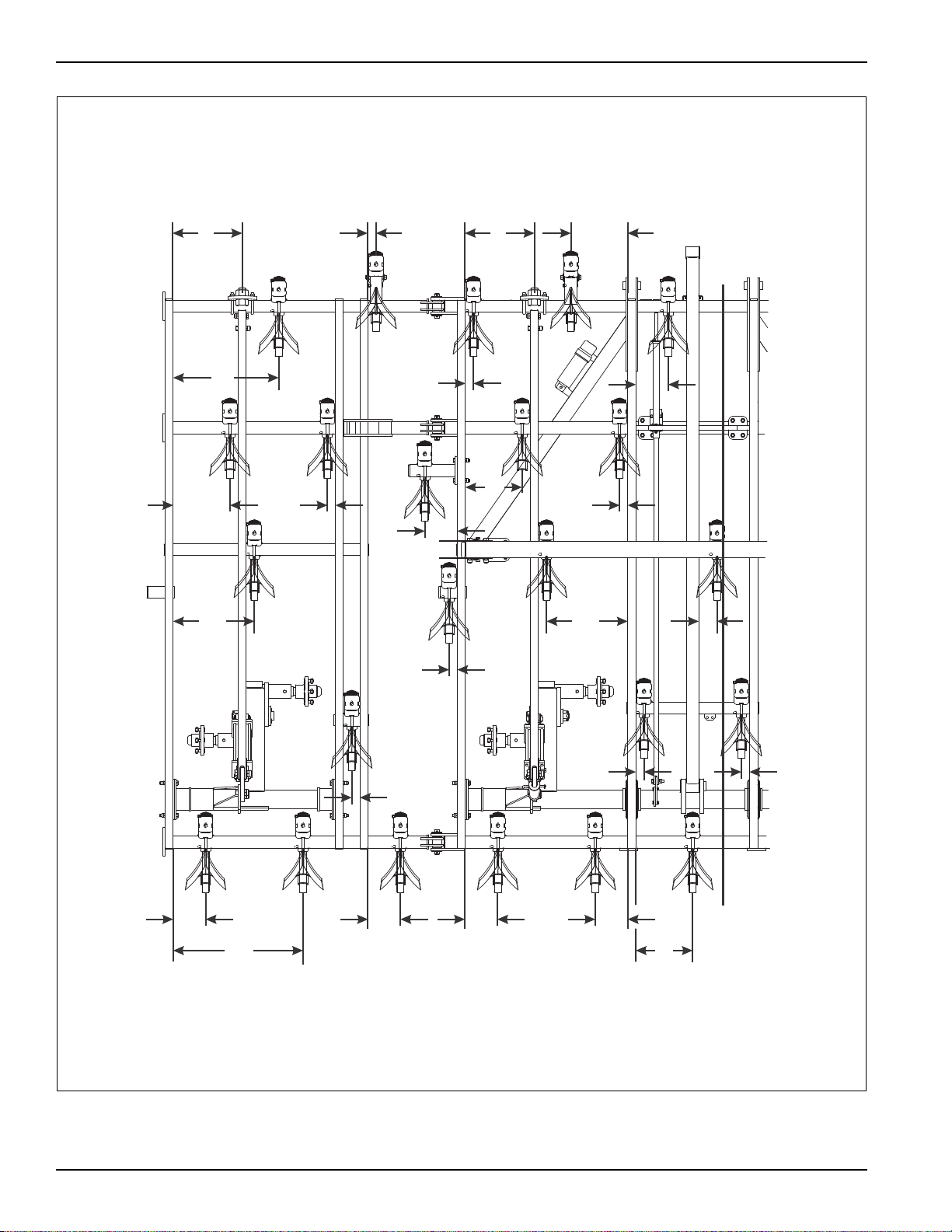
8
32
8
2
20
14
2
26
17 2
8
8
14220
8
2
2
8
14
2
2
8
17 14
9630-20place lt half
A
A
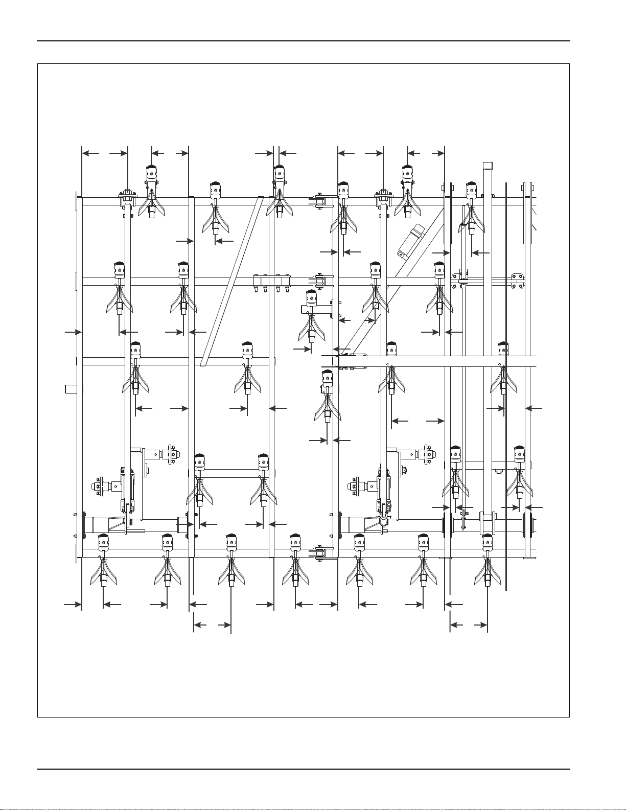
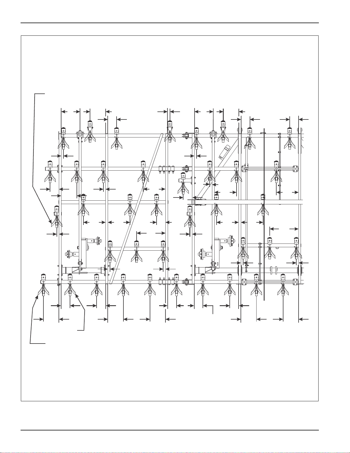
Figure 2-3: Shank Placement (20' Model)
(Left Half)
2-6 F-632-0114 Edition
STANDARD SPECIFICATIONS
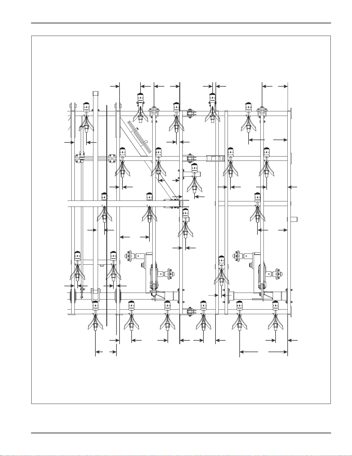
8328220142
26172
88
14
2
20
8
2 2
8
14
2
2
8
1714
9630-20place rt half
A
A
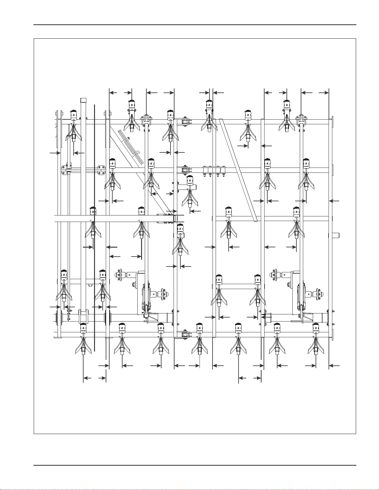
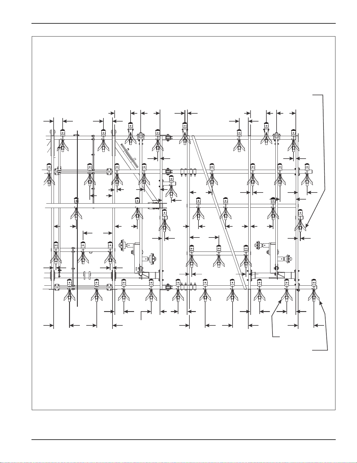
Figure 2-4: Shank Placement (20' Model)
(Right Half)
2-7
STANDARD SPECIFICATIONS
8
14
8
2
20
14
2
17 2
8
8
14220
8
2
2
8
14
2
2
8
17 14
8
14
8
2
8
9630-24place lt half
A
A
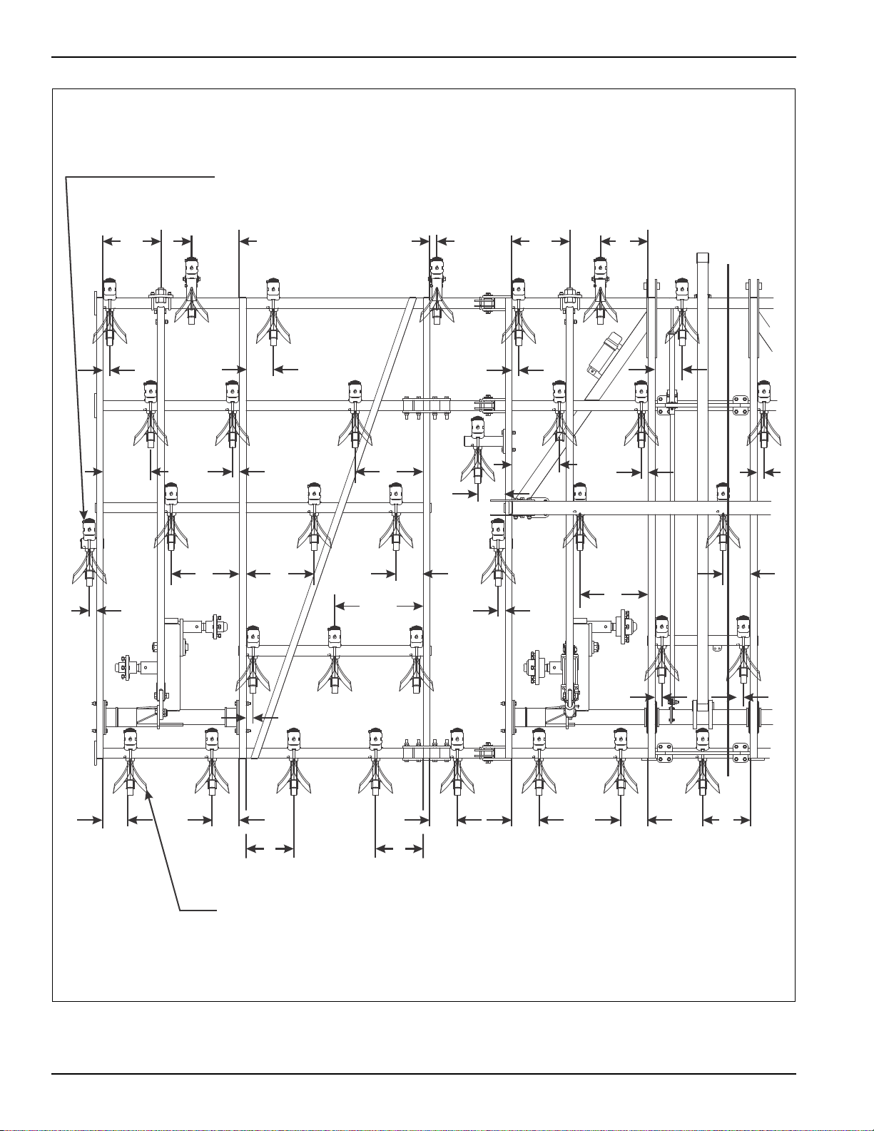
Figure 2-5: Shank Placement (24' Model)
(Left Half)
2-8 F-632-0114 Edition
STANDARD SPECIFICATIONS
8148
2
201421728814
2
20
8
2 2
8
14
2
2
8
1714
8148
2
8
9630-24place rt half
A
A
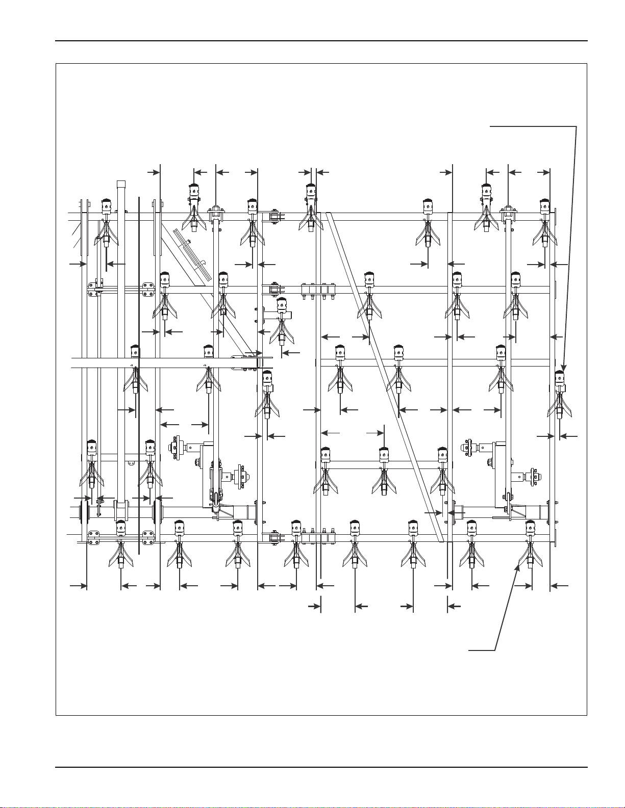
Figure 2-6: Shank Placement (24' Model)
(Right Half)
2-9
STANDARD SPECIFICATIONS
8
14
2
8
9630-30ncplace lt half
148881422
2
2
20 20
2682
82014
20
14
2
8
1417 2 1417
228
8
30’ NC MODEL
28’ MODEL
2
A
A
2-10 F-632-0114 Edition
Figure 2-7: Shank Placement (28’ and 30'NC Models)
(Left Half)
STANDARD SPECIFICATIONS
8
1428
9630-30ncplace rt half
14
88814
22222020
26
8
2
8
20
14
20
14281417
214 17
2
2
8
8
30’ NC MODEL
28’ MODEL
A
A
Figure 2-8: Shank Placement (28’ and 30'NC Models)
(Right Half)
2-11
STANDARD SPECIFICATIONS
8
9630-34place lt half
32’ MODEL
30’ MODEL
34’ MODEL
14
8
14814
7-3/4
8
14
14
2 2
26
20 20 8
20
2
14
8
2
2
17 14
8
17 14
8228220262220220820A
A
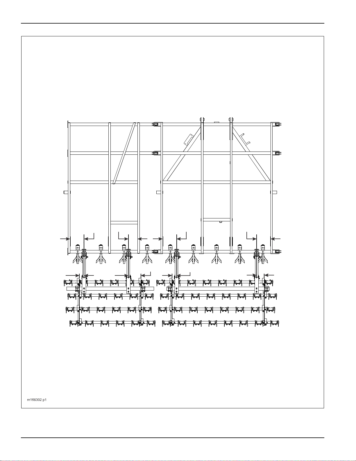
Figure 2-9: Shank Placement (30’, 32’, and 34' Models)
(Left Half)
2-12 F-632-0114 Edition
STANDARD SPECIFICATIONS
8
9630-34place rt half
32’ MODEL
30’ MODEL
34’ MODEL
14814814
7-3/4
8
14
14
22262020
8
20
214822
17148
1714
8
2
2
8
2
20
26
22
20
2 14
20
8
A
A
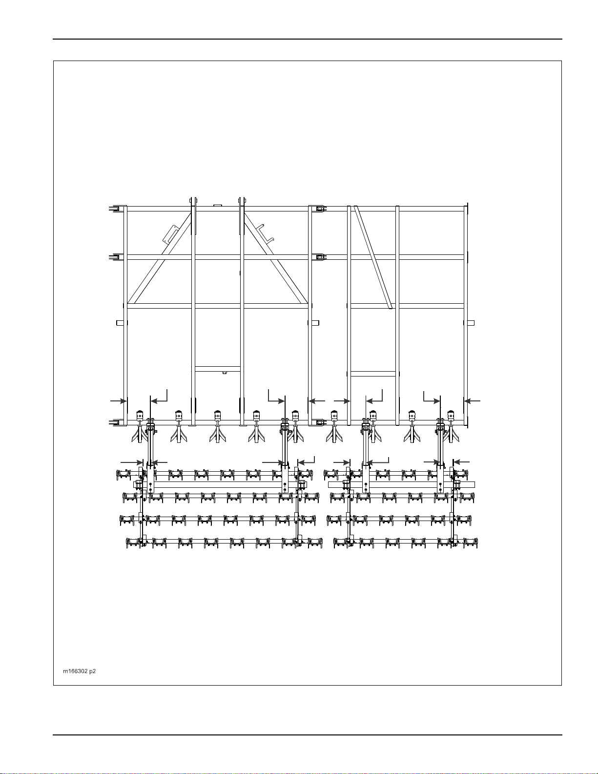
Figure 2-10: Shank Placement (30’, 32’, and 34' Models)
(Right Half)
2-13
STANDARD SPECIFICATIONS
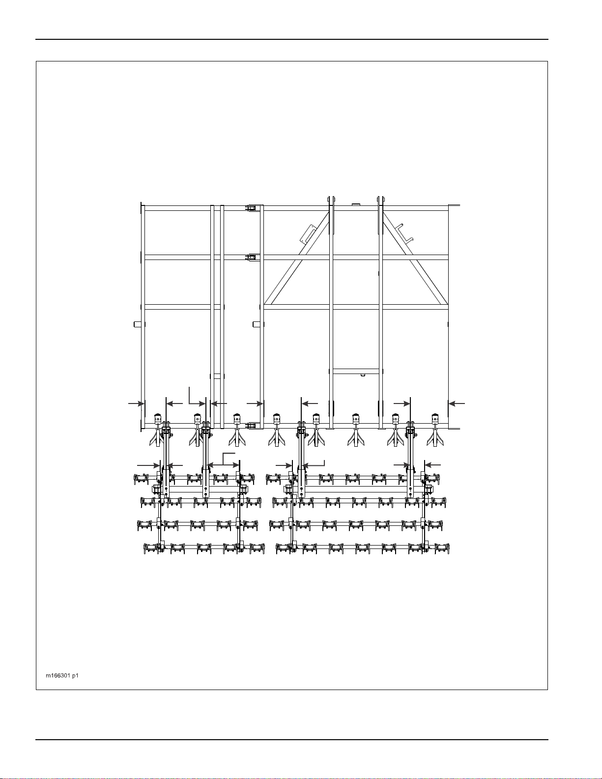
13
3-1/4
23
20-7/16
8-7/16
5 TINE 8 IN
HARROW ASSEMBLY
7 TINE 8 IN
HARROW ASSEMBLY
2-7/8
23
5-1/4
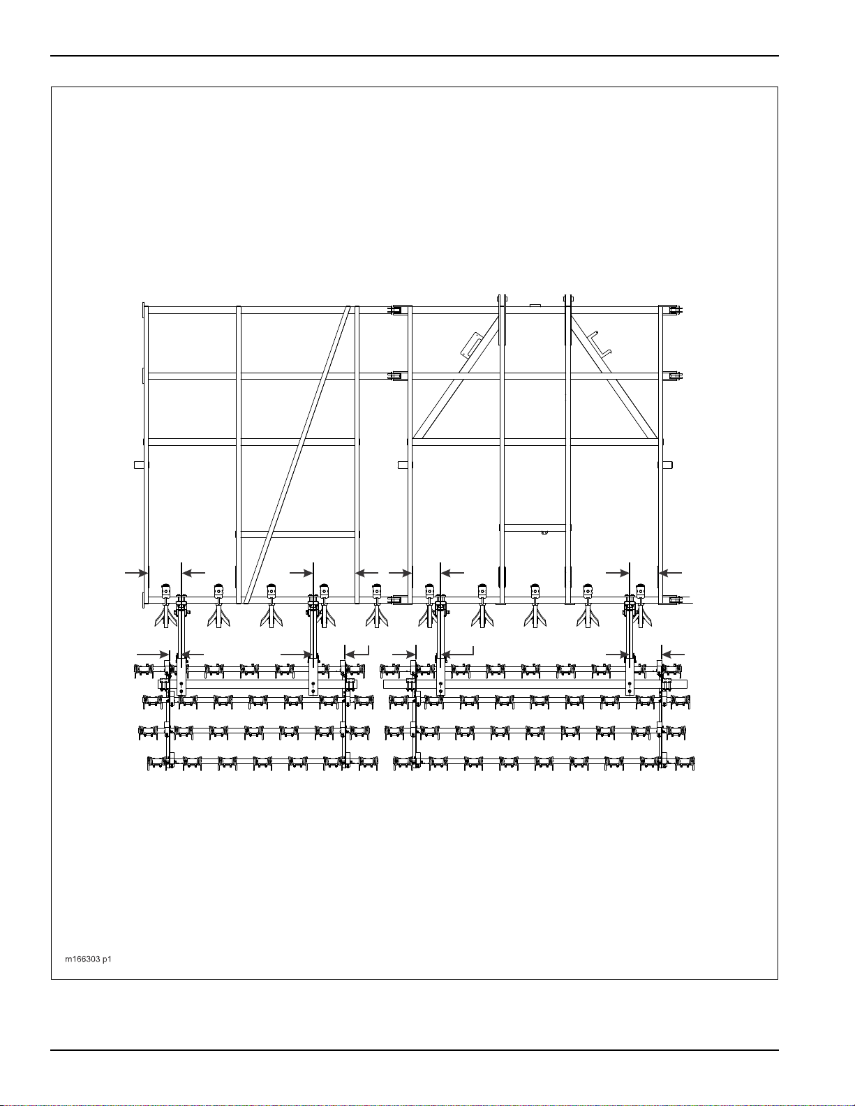
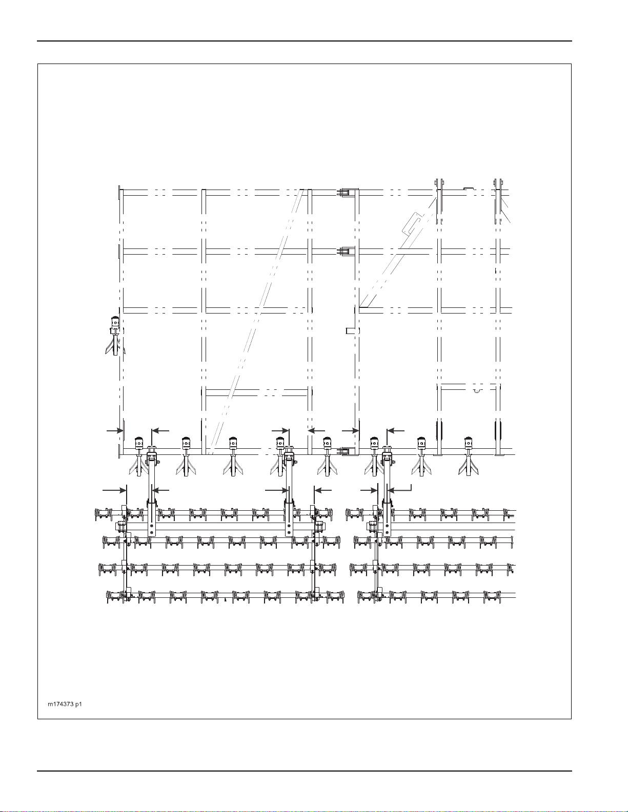
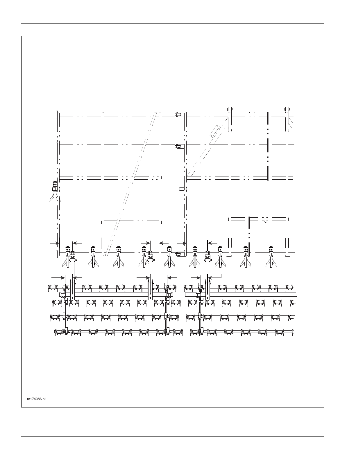
Figure 2-11: 4 Row Coil Tine Harrow Placement (20' Model)
2-14 F-632-0114 Edition
(Left Half)
STANDARD SPECIFICATIONS
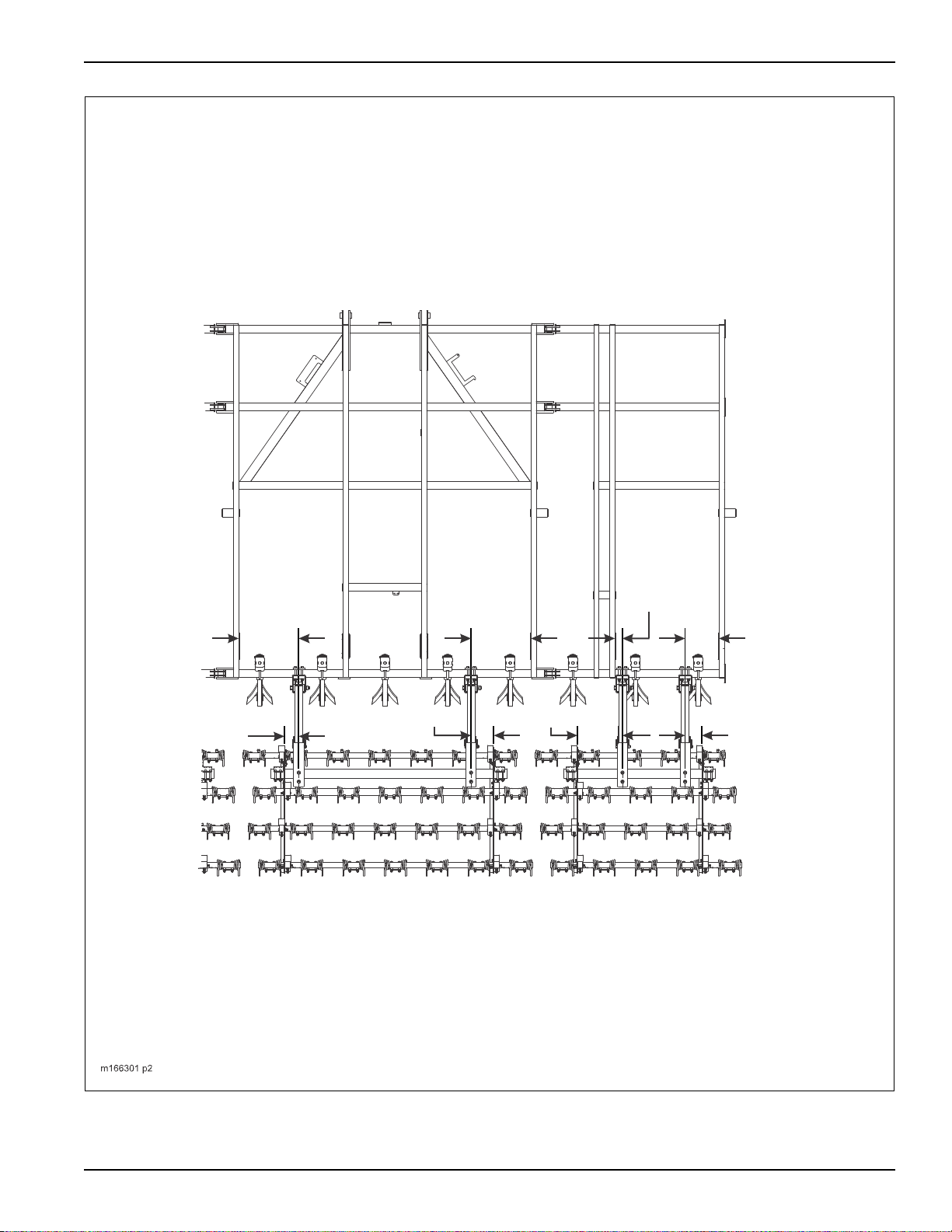
13
5-1/4
23
8-7/16
6-7/16
5 TINE 8 IN
HARROW ASSEMBLY
7 TINE 8 IN
HARROW ASSEMBLY
2-7/8
23
17-1/4
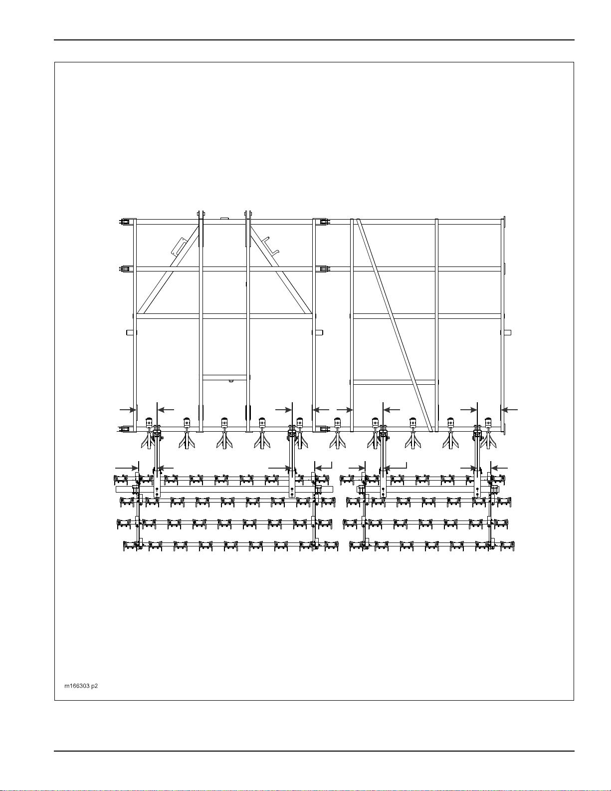
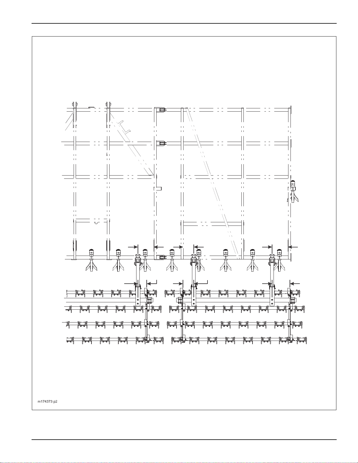
Figure 2-12: 4 Row Coil Tine Harrow Placement (20’ Model)
(Right Half)
2-15
STANDARD SPECIFICATIONS
14-1/2
4-3/4
14-1/2
12-15/16
7-15/16
6 TINE 8 IN
HARROW ASSEMBLY
8 TINE 8 IN
HARROW ASSEMBLY
9-1/2
14-1/2
4-3/4
2-16 F-632-0114 Edition
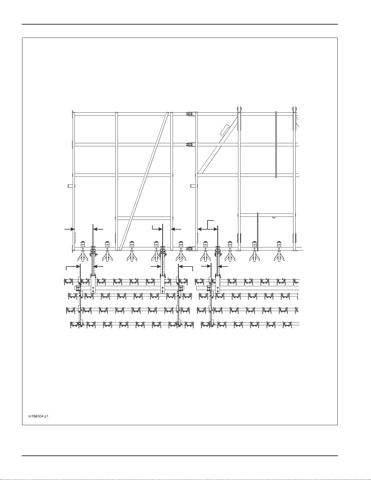
Figure 2-13: 4 Row Coil Tine Harrow Placement (24' Model)
(Left Half)
STANDARD SPECIFICATIONS
14-1/2
4-3/4
14-1/2
7-15/16
7-15/16
6 TINE 8 IN
HARROW ASSEMBLY
8 TINE 8 IN
HARROW ASSEMBLY
9-1/2
14-1/2
9-3/4
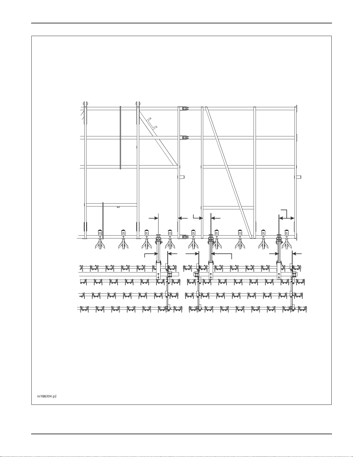
Figure 2-14: 4 Row Coil Tine Harrow Placement (24’ Model)
(Right Half)
2-17
STANDARD SPECIFICATIONS
15
5-1/4
13
14-7/16
14-7/16
7 TINE 8 IN
HARROW ASSEMBLY
9 TINE 8 IN
HARROW ASSEMBLY
19
13
11-1/4
Figure 2-15: 4 Row Coil Tine Harrow Placement (28' Model)
2-18 F-632-0114 Edition
(Left Half)
STANDARD SPECIFICATIONS
13
11-1/4
19
14-7/16
8-7/16
7 TINE 8 IN
HARROW ASSEMBLY
9 TINE 8 IN
HARROW ASSEMBLY
131511-1/4
Figure 2-16: 4 Row Coil Tine Harrow Placement (28’ Model)
(Right Half)
2-19
STANDARD SPECIFICATIONS
14-1/2
12-3/4
14-1/2
12-15/16
8 TINE 8 IN
HARROW ASSEMBLY
8 TINE 8 IN
HARROW ASSEMBLY
9-1/2
4-3/4
Figure 2-17: 4 Row Coil Tine Harrow Placement (30’NC Model)
2-20 F-632-0114 Edition
(Left Half)
STANDARD SPECIFICATIONS
9-1/2
7-15/16
15-15/16
8 TINE 8 IN
HARROW ASSEMBLY
8 TINE 8 IN
HARROW ASSEMBLY
14-1/2
14-1/2
9-3/4
Figure 2-18: 4 Row Coil Tine Harrow Placement (30’NC Model)
(Right Half)
2-21
STANDARD SPECIFICATIONS
18
12-1/4
8
15-7/16
20
6-1/4
8 TINE 8 IN
HARROW ASSEMBLY
9 TINE 8 IN
HARROW ASSEMBLY
Figure 2-19: 4 Row Coil Tine Harrow Placement (30' Model)
2-22 F-632-0114 Edition
(Left Half)
STANDARD SPECIFICATIONS
20
9-7/16
8
12-1/4
16
13-7/16
9 TINE 8 IN
HARROW ASSEMBLY
8 TINE 8 IN
HARROW ASSEMBLY
Figure 2-20: 4 Row Coil Tine Harrow Placement (30’ Model)
(Right Half)
2-23
STANDARD SPECIFICATIONS
12-1/2
6-3/4
20
15-7/16
8 TINE 8 IN
HARROW ASSEMBLY
9 TINE 8 IN
HARROW ASSEMBLY
8
6-1/4
2-24 F-632-0114 Edition
Figure 2-21: 4 Row Coil Tine Harrow Placement (32' Model)
(Left Half)
 Loading...