

Page 1

Till ‘N Seed
®
Models BPS6 and BPSB6
Operator’s Manual
LANDOLL CORPORATION
1900 North Street
Marysville, Kansas 66508
(785) 562-5381
800-428-5655 ~ WWW.LANDOLL.COM
311rev0313 3P091
Page 2

Page 3

1 Safety Information
Introduction . . . . . . . . . . . . . . . . . . . . . . . . . . . . . . . . . . . . . . . . . . . . . . . . . . . . . . . . . . . . . . . . . . 1-1
Description of Unit . . . . . . . . . . . . . . . . . . . . . . . . . . . . . . . . . . . . . . . . . . . . . . . . . . . . . . . . . . . . . 1-1
Using this Manual . . . . . . . . . . . . . . . . . . . . . . . . . . . . . . . . . . . . . . . . . . . . . . . . . . . . . . . . . . . . . 1-1
Owner Assistance . . . . . . . . . . . . . . . . . . . . . . . . . . . . . . . . . . . . . . . . . . . . . . . . . . . . . . . . . . . . . 1-1
Warranty Registration . . . . . . . . . . . . . . . . . . . . . . . . . . . . . . . . . . . . . . . . . . . . . . . . . . . . . . . . . . 1-1
Understanding Safety Statements . . . . . . . . . . . . . . . . . . . . . . . . . . . . . . . . . . . . . . . . . . . . . . . . 1-2
Transporting Safety . . . . . . . . . . . . . . . . . . . . . . . . . . . . . . . . . . . . . . . . . . . . . . . . . . . . . . . . . . . . 1-2
Attaching, Detaching, Storage . . . . . . . . . . . . . . . . . . . . . . . . . . . . . . . . . . . . . . . . . . . . . . . . . . . 1-3
Maintenance Safety . . . . . . . . . . . . . . . . . . . . . . . . . . . . . . . . . . . . . . . . . . . . . . . . . . . . . . . . . . . . 1-4
Air Shock Safety . . . . . . . . . . . . . . . . . . . . . . . . . . . . . . . . . . . . . . . . . . . . . . . . . . . . . . . . . . . . . . . 1-4
Protective Equipment . . . . . . . . . . . . . . . . . . . . . . . . . . . . . . . . . . . . . . . . . . . . . . . . . . . . . . . . . . 1-4
Table of Contents
Chemical Safety . . . . . . . . . . . . . . . . . . . . . . . . . . . . . . . . . . . . . . . . . . . . . . . . . . . . . . . . . . . . . . . 1-4
Prepare for Emergencies . . . . . . . . . . . . . . . . . . . . . . . . . . . . . . . . . . . . . . . . . . . . . . . . . . . . . . . . 1-4
Safety Signs . . . . . . . . . . . . . . . . . . . . . . . . . . . . . . . . . . . . . . . . . . . . . . . . . . . . . . . . . . . . . . . . . . 1-5
2 Operation
Operation of Till ‘N Seed . . . . . . . . . . . . . . . . . . . . . . . . . . . . . . . . . . . . . . . . . . . . . . . . . . . . . . . . 2-1
Attaching to a Tractor . . . . . . . . . . . . . . . . . . . . . . . . . . . . . . . . . . . . . . . . . . . . . . . . . . . . . . 2-2
Front Seedbox Seed Chart . . . . . . . . . . . . . . . . . . . . . . . . . . . . . . . . . . . . . . . . . . . . . . . . . . 2-4
Rear Seedbox Seed Chart . . . . . . . . . . . . . . . . . . . . . . . . . . . . . . . . . . . . . . . . . . . . . . . . . . 2-6
Seed Rate . . . . . . . . . . . . . . . . . . . . . . . . . . . . . . . . . . . . . . . . . . . . . . . . . . . . . . . . . . . . . . . 2-7
Rear Seedbox . . . . . . . . . . . . . . . . . . . . . . . . . . . . . . . . . . . . . . . . . . . . . . . . . . . . . . . . . . . . 2-9
Seed Rate Calibration . . . . . . . . . . . . . . . . . . . . . . . . . . . . . . . . . . . . . . . . . . . . . . . . . . . . . . . . . 2-10
Front Seedbox . . . . . . . . . . . . . . . . . . . . . . . . . . . . . . . . . . . . . . . . . . . . . . . . . . . . . . . . . . . 2-10
Rear Seedbox . . . . . . . . . . . . . . . . . . . . . . . . . . . . . . . . . . . . . . . . . . . . . . . . . . . . . . . . . . .2-11
Seeding . . . . . . . . . . . . . . . . . . . . . . . . . . . . . . . . . . . . . . . . . . . . . . . . . . . . . . . . . . . . . . . . . . . . . 2-12
Air Shock . . . . . . . . . . . . . . . . . . . . . . . . . . . . . . . . . . . . . . . . . . . . . . . . . . . . . . . . . . . . . . . . . . . 2-13
Gage Wheels . . . . . . . . . . . . . . . . . . . . . . . . . . . . . . . . . . . . . . . . . . . . . . . . . . . . . . . . . . . . . . . . . 2-14
Rotor Thrust Guide . . . . . . . . . . . . . . . . . . . . . . . . . . . . . . . . . . . . . . . . . . . . . . . . . . . . . . . . . . . 2-15
Lift and Tie-Down . . . . . . . . . . . . . . . . . . . . . . . . . . . . . . . . . . . . . . . . . . . . . . . . . . . . . . . . . . . . . 2-16
Storage . . . . . . . . . . . . . . . . . . . . . . . . . . . . . . . . . . . . . . . . . . . . . . . . . . . . . . . . . . . . . . . . . . . . . 2-17
3 Optional Equipment Instructions
Acre Meter Kit 3P099 Installation . . . . . . . . . . . . . . . . . . . . . . . . . . . . . . . . . . . . . . . . . . . . . . . . . 3-1
i
Page 4

Acre Meter Operations . . . . . . . . . . . . . . . . . . . . . . . . . . . . . . . . . . . . . . . . . . . . . . . . . . . . . . . . . . 3-3
Settings for Loup Acre Meters After 05/15/2012 . . . . . . . . . . . . . . . . . . . . . . . . . . . . . . . . . . 3-3
Quick-start Settings for Loup Acre Meters Prior to 05/15/2012 . . . . . . . . . . . . . . . . . . . . . . . 3-4
Acre Meter Settings (After 05/15/2012) . . . . . . . . . . . . . . . . . . . . . . . . . . . . . . . . . . . . . . . . . 3-5
Acre Meter Settings (Prior to 05/15/2012) . . . . . . . . . . . . . . . . . . . . . . . . . . . . . . . . . . . . . . . 3-6
Small Seedbox Kit 3P100 . . . . . . . . . . . . . . . . . . . . . . . . . . . . . . . . . . . . . . . . . . . . . . . . . . . . . . . . 3-7
4 Maintenance
Fasteners . . . . . . . . . . . . . . . . . . . . . . . . . . . . . . . . . . . . . . . . . . . . . . . . . . . . . . . . . . . . . . . . 4-1
Lubrication . . . . . . . . . . . . . . . . . . . . . . . . . . . . . . . . . . . . . . . . . . . . . . . . . . . . . . . . . . . . . . . 4-2
Chain Tension . . . . . . . . . . . . . . . . . . . . . . . . . . . . . . . . . . . . . . . . . . . . . . . . . . . . . . . . . . . . 4-4
Rotor Thrust Guide . . . . . . . . . . . . . . . . . . . . . . . . . . . . . . . . . . . . . . . . . . . . . . . . . . . . . . . . 4-6
Rotor Blade . . . . . . . . . . . . . . . . . . . . . . . . . . . . . . . . . . . . . . . . . . . . . . . . . . . . . . . . . . . . . . 4-7
Firming Roller . . . . . . . . . . . . . . . . . . . . . . . . . . . . . . . . . . . . . . . . . . . . . . . . . . . . . . . . . . . . 4-7
Maintenance Chart . . . . . . . . . . . . . . . . . . . . . . . . . . . . . . . . . . . . . . . . . . . . . . . . . . . . . . . . . . . . . 4-8
Troubleshooting . . . . . . . . . . . . . . . . . . . . . . . . . . . . . . . . . . . . . . . . . . . . . . . . . . . . . . . . . . . . . . . 4-9
5 Reference Tables and Specifications
ii
Page 5

Chapter 1
DANGER
NOTE
Safety Information
Introduction
The implement described in this manual has been
designed with care and built by skilled workers using
quality materials and processes. Proper assembly,
maintenance and safe operation will allow this machine
to provide you with satisfactory use for seasons to come.
Read this entire manual before attempting to
assemble, adjust or operate this machine.
Failure to comply with this warning can result in
personal injury or death, damage
or its components and inferior operation.
to the machine
Description of Unit
The Brillion Till 'N Seed is a tractor mounted, ground
driven, minimum till seeder designed to plant a variety of
seed into previously untilled or lightly tilled soil which is
relatively firm. It can also be used to lightly till soil without
seeding, de-thatch lawns, and shred tall dead grass. The
machine employs a drive rotor, followed by a tillage rotor
and finally a firming roller. Seed is dropped onto the
ground ahead of the drive rotor and is incorporated in the
soil by the tillage rotor.
Owner Assistance
If customer service or repairs are needed, contact your
Brillion dealer. They have trained personnel, parts and
service equipment specially designed for Brillion
products. Your machine’s parts should only be replaced
with Brillion parts. Have the Serial Number and complete
Model Number available when ordering parts from your
Brillion dealer. See Figure 1-1.
Warranty Registration
Brillion Farm Equipment, by Landoll, shall have no
warranty obligation unless each product is registered,
within 10 days of retail purchase, using the Landoll
Corporation Ag Products on-line registration process.
Please refer to the Ag Products Policy and Procedures
Manual, accessible at www.landoll.com
instructions regarding product registration.
Enter your product information below for quick reference.
MODEL NUMBER
SERIAL NUMBER
for step by step
The machine shown in the following illustrations may not
agree with your unit. Your assembled machine, however,
is similar for all models. Additional parts identification and
location can be obtained by reviewing the parts catalog.
Using this Manual
This manual will familiarize you with safety, assembly,
operation, adjustment, and maintenance. Read this
manual and follow the recommendations to help ensure
safe and efficient operation.
• The information in this manual is current at time of
printing. Some parts may change to assure top
performance.
• Location reference: Right and Left designations in this
manual are determined by facing the direction the
machine will travel during field operation, unless
otherwise stated.
DATE OF PURCHASE
Figure 1-1: ID Plate
1-1
Page 6

SAFETY INFORMATION
NOTE
NOTICE
CAUTION
WARNING
DANGER
NOTE
DANGER
IMPORTANT
Federal law requires that you explain the safety and
operating instructions furnished with this machine to all
operators before they are allowed to operate the
machine. These instructions must be repeated to the
operators at the beginning of each season. Be sure to
observe and follow the instructions for the safety of
anyone operating or near the machine.
Investigation has shown that nearly 1/3 of all farm
accidents are caused by careless use of machinery.
Insist that all people working with you or for you abide by
all safety instructions.
Understanding Safety Statements
You will find various types of safety information on the
following pages and on the machine decals (signs)
attached to the implement. This section explains their
meaning.
Special notice - read and thoroughly understand.
• Keep these signs clean so they can be observed
readily. It is important to keep these decals cleaned
more frequently than the machine. Wash with soap
and water or a cleaning solution as required.
• Replace decals that become damaged or lost. Also, be
sure that any new machine components installed
during repair include decals which are assigned to
them by the manufacturer.
• When applying decals to the machine, be sure to
clean the surface to remove any dirt or residue. Where
possible, sign placement should protect the sign from
abrasion, damage, or obstruction from mud, dirt, oil
etc.
• Keep Riders Off of Machinery
Do not allow anyone to ride on tractor or
machine. Riders could be struck by foreign
objects or thrown from the machine.
• Never allow children to operate equipment.
• Keep bystanders away from machine during
operation.
Proceed with caution. Failure to heed caution
cause injury to person or damage product.
may
Proceed with caution. Failure to heed warning will
cause injury to person or damage product.
Proceed with extreme caution. Failure to heed
notice will cause injury or death to person and/or
damage product.
You should read and understand the information
contained in this manual and on the machine decals
before you attempt to operate or maintain this equipment.
• Examine safety decals and be sure you have the
correct safety decals for the machine. See Safety Sign
and Locations in Safety Section for decal locations,
See Figures 1-3,1-4,1-5 and 1-6. Order replacement
decals through your Brillion dealer.
Transporting Safety
It is the responsibility of the owner/operator to
comply with all state and local laws.
• When transporting the machine on a road or highway,
use adequate warning symbols, reflectors, lights and
slow moving vehicle sign as required. Slow moving
tractors and towed implements can create a hazard
when driven on public roads. They are difficult to see,
especially at night.
• Do not tow an implement that, when fully loaded,
weighs more than 1.5 times the weight of the towing
vehicle.
• Carry reflectors or flags to mark the tractor and
implement in case of breakdown on the road.
• Do not transport at speeds over 20 MPH under good
conditions. Never travel at a speed which does not
allow adequate control of steering and stopping.
Reduce speed if towed load is not equipped with
brakes.
• Avoid sudden stops or turns because the weight of the
machine may cause the operator to lose control of the
tractor. Use a tractor heavier than the machine.
• Use caution when towing behind articulated steering
tractors; fast or sharp turns may cause the machine to
shift sideways.
1-2 3P091
Page 7

SAFETY INFORMATION
Rockshaft Clamp
Tighten Rockshaft Clamp
Nut to prevent movement
Insert Rockshaft
Lock Detent Pin
• Keep clear of overhead power lines and other
obstructions when transporting. Know transport height
and width of your machine.
• Install Rockshaft Lock Detent Pin and tighten
Rockshaft Clamp prior to tying it down onto trailer. See
Chapter 2 Operation. Failure to do so may result in tie
downs becoming loose and machine damage.
Attaching, Detaching, Storage
• Do not stand between the tractor and implement
when attaching or detaching implement unless both
are not moving.
• After attaching implement to the tractor and prior to
lifting the machine, loosed nut on Rockshaft Clamp
enough to allow movement and remove the
Rockshaft Lock Detent Pin. Insert Detent Pin in
storage hole on Rockshaft Arm. Raise stand
• Before detaching implement from the tractor, lower
machine to the ground and tighten nut on the
Rockshaft Clamp to prevent movement. Install
Rockshaft Lock Detent Pin if Rockshaft Lock Slot
aligns with Frame Tab Hole. Lower stand. See
Figure 1-2.
Figure 1-2: Rockshaft Lock
1-3
Page 8

SAFETY INFORMATION
NOTE
Maintenance Safety
• Block the machine so it will not roll when working on or
under it to prevent injury in case of hydraulic failure or
inadvertent lowering by another person.
• Do not make adjustments or lubricate machine while it
is in motion.
• Make sure all moving parts have stopped and all
system pressure is relieved.
• Keep all guards in place. Replace any that become
damaged.
• Understand the procedure before doing the work. Use
proper tools and equipment. See Table 4-1 for
additional information.
On most tractors relieving hydraulic pressure can be
accomplished by operating valves after the engine is
stopped. Also, the machine should be lowered to ground
so that the shanks are taking the load.
Wear protective gloves and safety glasses or goggles
when working with hydraulic systems.
Protective Equipment
• Wear protective clothing and equipment.
• Wear clothing and equipment appropriate for the job.
Avoid loose fitting clothing.
• Because prolonged exposure to loud noise can cause
hearing impairment or hearing loss, wear suitable
hearing protection, such as earmuffs or earplugs.
Chemical Safety
• Agricultural chemicals can be dangerous. Improper
use can seriously injure persons, animals, plants, soil
& property.
• Read chemical manufacture’s instructions and store or
dispose of unused chemicals as specified.
• Handle chemicals with care and avoid inhaling smoke
from any type of chemical fire.
• Store or dispose of unused chemicals as specified by
the chemical manufacturer.
Prepare for Emergencies
Air Shock Safety
• Wear protective gloves and safety glasses or goggles
when working with the Air Shock.
• The pressurized Air Shock may violently extend if
disconnected from the machine. Release air pressure
prior to removing.
• Keep a First Aid Kit and Fire Extinguisher handy
• Keep emergency numbers for doctor, ambulance,
hospital and fire department near phone.
1-4 3P091
Page 9

Safety Signs
AMBER REFLECTIVE
P/N 528934
WARNING UNHITCHING
P/N 3P074
CAUTION DO NOT LIST
P/N 8J310
FRONT
3P074
CAUTION
1. DO NOT LUBRICATE, ADJUST OR REPAIR WHEN MACHINE IS IN MOTION.
2. DO NOT TOW OR TRANSPORT FASTER THAN 15 MILES PER HOUR.
3. DO NOT RIDE OR ALLOW OTHERS TO RIDE ON THE MACHINE.
4. BLOCK UP ALL HYDRAULICALLY OR MECHANICALLY RAISED COMPONENTS TO PREVENT
UNINTENDED LOWERING OR LOWER THE MACHINE TO THE GROUND TO MAKE ADJUSTMENT
OR REPAIRS OR WHEN NOT IN USE.
5. KEEP ALL PERSONS AWAY FROM MACHINE DURING HITCHING AND OPERATING.
6. SLOW DOWN BEFORE MAKING SHARP TURNS OR USING THE BRAKE.
DRIVE SLOWLY OVER ROUGH GROUND, SIDE HILLS, AND AROUND CURVES TO AVOID TIPPING.
7. COMPLY WITH ALL LAWS WHEN TRANSPORTING THE MACHINE ON PUBLIC ROADWAYS.
8. INSTRUCT ALL OPERATORS IN THE SAFE OPERATION OF THE MACHINE.
REVIEW THE OPERATOR’S MANUAL FOR CORRECT PROCEDURES.
9. BLOCK IMPLEMENT TO PREVENT MOVEMENT WHEN UNHITCHED FROM TRACTOR.
10. KEEP ALL GUARDS AND SHIELDS IN PLACE WHILE MACHINE OR PARTS ARE IN MOTION.
8J310
SAFETY INFORMATION
Figure 1-3: Safety Signs (1 of 3)
1-5
Page 10

SAFETY INFORMATION
FRONT
PARKING STAND
P/N 3P078
ROCKSHAFT CLAMP
P/N 3P075
DO NOT LIFT
P/N 3P077
FRONT
3P075
1-6 3P091
Figure 1-4: Safety Signs (2 of 3)
Page 11

WARNING MOVING
PART HAZARD
P/N 2K123
RED REFLECTIVE
P/N 528933
ORANGE STRIPE
P/N 528938
!
WARNING
MOVING PART HAZARD
2K123
FRONT
SAFETY INFORMATION
Figure 1-5: Safety Signs (3 of 3)
1-7
Page 12

SAFETY INFORMATION
FRONT
FRONT BOX SEED CHART
P/N 3P158
REAR BOX SEED CHART
P/N 3P159
IMPORTANT
LIFTING AND TIE DOWN
P/N 3P073
PLANTING RATES
3P158 FOR TILL 'N SEED
PLANTING RATES
3P159 FOR TILL 'N SEED
45°
MIN
LIFT FROM
HERE ONLY
FOR TIE
DOWN ONLY
FOR TIE
DOWN ONLY
TO PREVENT DAMAGE TO MACHINE:
LIFT AND TIE MACHINE DOWN ONLY
AS SHOWN.
IMPORTANT
DO NOT LIFT
FROM HERE
3P073
DO NOT LIFT
FROM HERE
1-8 3P091
Figure 1-6: Decals (1 of 2)
Page 13

SAFETY INFORMATION
CALIBRATION CHART
P/N 3P076
TRANSMISSION LAYOUT
P/N 3P160
SEED DRIVE
DISCONNECT
PIN - FRONT BOX
LEFT END VIEW OF MACHINE
5/8" HEX FOR
FRONT BOX
CALIBRATION
TURN CW
5/8" HEX FOR
REAR BOX
CALIBRATION
TURN CCW
FRONT ROTOR AXLE
HIGH
RANGE
MID
RANGE
LOW
RANGE
19T DRIVER
23T DRIVEN
23T DRIVEN
37T DRIVEN
13T DRIVER
10T DRIVER
CALIBRATION TROUGH:
SEEDING POSITION
SEED DRIVE
DISCONNECT
PIN - REAR BOX
VIEW FROM INSIDE OF LEFT END PLATE
CALIBRATION TROUGH:
COLLECTION POSITION
TRANSMISSION LAYOUT
3P160 FOR TILL 'N SEED
3P076 FOR TILL 'N SEED
SEED RATE CALIBRATION
PLACE CALIBRATION TROUGH IN COLLECTION POSITION OR PLACE TARP UNDER
FRONT OF MACHINE. REFER TO SEED CHARTS ON THE SEED BOX COVERS TO
DETERMINE INITIAL SEED METER SETTINGS. IF YOU NEED TO ADJUST SEED
METERS FOR REDUCED OUTPUT WHILE THEY ARE FILLED WITH SEED, THE SEED
METER SHAFT MUST BE TURNED WHILE MAKING THE ADJUSTMENT.
FRONT SEEDBOX
1. IDENTIFY LOWEST TRANSMISSION RANGE EXPECTED TO ACHIEVE SEED RATE
2. ADJUST SEED METER SETTING
3. REMOVE SEED DRIVE DISCONNECT PIN - FRONT BOX
4. PRIME METERS: TURN 5/8" HEX FOR FRONT BOX CALIBRATION CW UNTIL ALL
METERS ARE DISCHARGING SEED. EMPTY CALIBRATION TROUGH OR TARP
5. COUNTING REVOLUTIONS, TURN THE 5/8" HEX CW TO METER OUT SEED
6. WEIGH THE SEED
7. CALCULATE SEED RATE:
LBS OF SEED x A 252 (LOW RANGE)
SEED RATE (LBS / ACRE) = ------------------------------ A= 528 (MID RANGE)
CALIBRATION REVS 771 (HIGH RANGE)
8. ADJUST METERS AND RE-CALIBRATE AS NECESSARY
9. ENSURE TRANSMISSION IS SET UP FOR PROPER SEEDING RANGE
10. RE-INSTALL SEED DRIVE DISCONNECT PIN - FRONT BOX
11. RE-INSTALL CALIBRATION TROUGH IN SEEDING POSITION
REAR SEEDBOX
1. ADJUST SEED METER SETTING
2. REMOVE SEED DRIVE DISCONNECT PIN - REAR BOX
3. PRIME METERS: TURN 5/8" HEX FOR REAR BOX CALIBRATION CCW UNTIL ALL
METERS ARE DISCHARGING SEED. EMPTY CALIBRATION TROUGH OR TARP
4. COUNTING REVOLUTIONS, TURN THE 5/8" HEX CCW TO METER SEED
5. WEIGH THE SEED
6. CALCULATE SEED RATE:
LBS OF SEED x 143
SEED RATE (LBS / ACRE) = ------------------------------ CALIBRATION REVS
7. ADJUST METERS AND RE-CALIBRATE AS NECESSARY
8. RE-INSTALL SEED DRIVE DISCONNECT PIN - REAR BOX
9. RE-INSTALL CALIBRATION TROUGH IN SEEDING POSITION
FRONT
Figure 1-7: Decals (2 of 2)
1-9
Page 14

SAFETY INFORMATION
SMV SIGN
P/N 2P151
FRONT
Figure 1-8: Slow Moving Vehicle Sign
1-10 3P091
Page 15

Operation of Till ‘N Seed
DANGER
WARNING
Chapter 2
Operation
Your BRILLION TILL 'N SEED is fully assembled from
the factory. This section refers to how to
successfully operate your machine. Refer to the
Parts Manual 3P092 for complete part breakdowns.
Be sure to read and understand the Safety
Procedures and Cautions starting on page 1-2.
"Left" and "Right" designation is determined by facing the
direction the machine will travel during field operation,
unless otherwise stated.
• If pre-assembled parts or fasteners are temporarily
removed, remember where they go. It is best to keep
parts separated.
• Check that all working parts move freely, bolts are tight
and cotter pins are spread.
• Refer to the Torque Chart in Chapter 4 for proper bolt
torque values.
Note the different torque requirement for bolts with lock
nuts. Refer to Torque Chart in Chapter 4.
Always be sure the front of the tractor has
enough weight to maintain control when the
machine is raised.
When transporting on roadways, obey all
applicable laws and regulations.
Do not transport at speeds over 20 mph under
good conditions. never travel at a speed which
does not allow adequate control of steering or
stopping.
Avoid sudden stops or turns because the weight
of the machine may cause the operator to lose
control of the tractor.
Make sure your slow moving vehicle sign is clean
and visible.
Figure 2-1: Till ‘N Seed Concept
2-1
Page 16

OPERATION
26"
Cat I
O
F
F
SET
31 5/8" Cat II
O
F
F
S
ET
Attaching to a Tractor
• Your implement requires a tractor with a lift capacity of
2,150 lbs, 24 inches behind the lift pins. Compatible
with Three Point Hitch Category I or II, Quick Attach
Category I or II, and iMatchTM.
• If an offset is required for wider tractors, move the
Three Point Hitch towards the transmission side of the
machine. See Figure 2-2.
2-2 3P091
Figure 2-2: 3 Point Hitch
Page 17

• After attaching the implement to the tractor and prior to
Rockshaft Lock Detent Pin
Storage Position
Stand Pin
Remove Rockshaft
Lock Detent Pin
Rockshaft Clamp
Loosen Rockshaft
Clamp Nut enough
to allow movement
lifting the machine, loosen the nut on Rockshaft Clamp
enough to allow movement and remove the Rockshaft
Lock Detent Pin. Insert Detent Pin in the storage hole
on Rockshaft Arm. Raise the Stand. See Figure 2-3.
OPERATION
.
Figure 2-3: Rockshaft Lock
2-3
Page 18
OPERATION
Al falfa
Bahia
Barley
Bermuda Grass
Bermuda Grass
(Unhulled)
Birdsfood
Trefoil
Bluegrass,
Kentucky
Buckwheat
Centipede Grass
Chicory Forage,
Coated
Clover, Alsike
Clover, Red
Notes
Range
INDICATOR SETTINGS INDICATOR SETTINGS
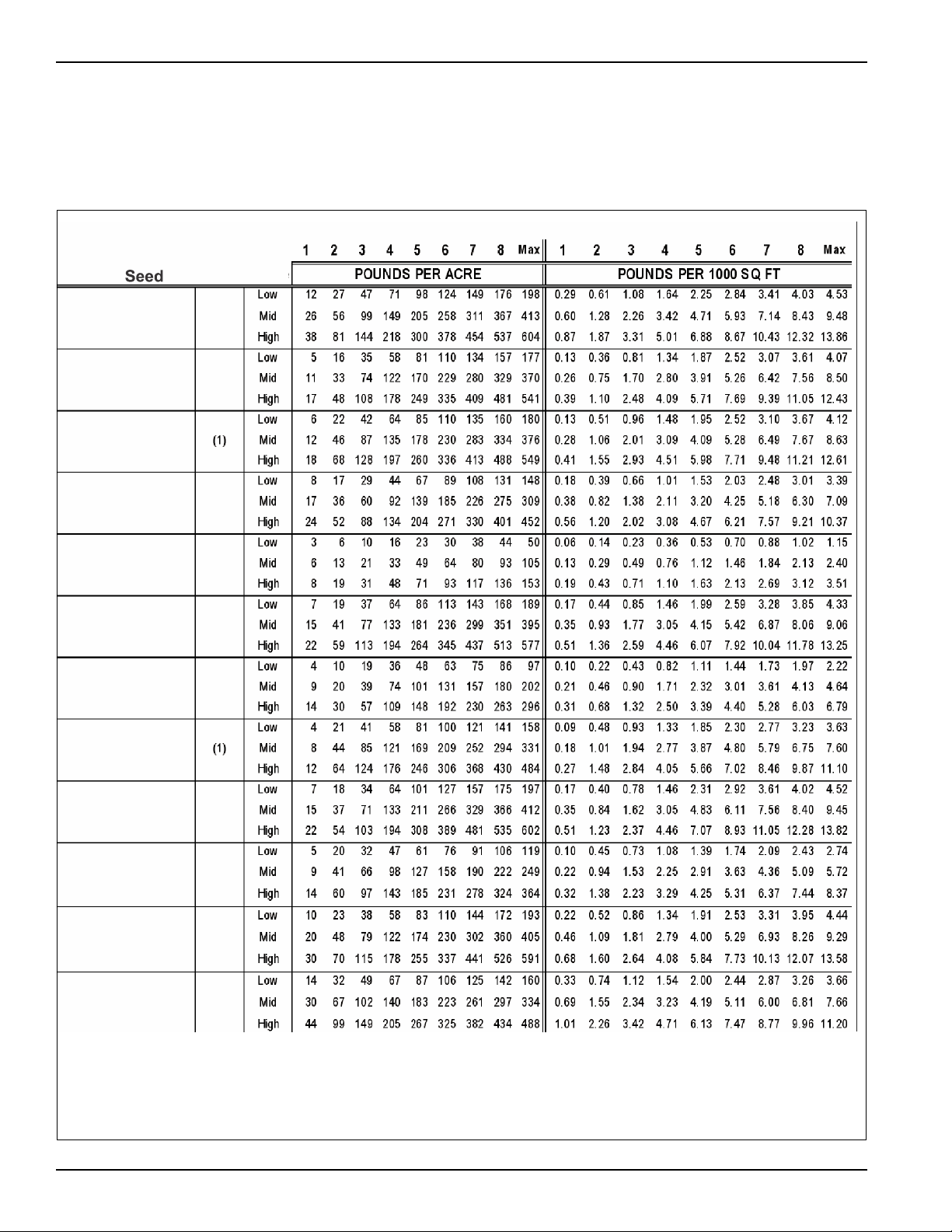
Front Seedbox Seed Chart
Rates are intended as a guide only. Variations in size and
cleanliness will affect rates. Calibrate desired seed for
best results. Front Box 5K141 Seed Meters. (1 ACRE =
43,560 SQ. FT. = 6 FT wide x 1-3/8 mile. See Figures 2-4
and 2-5.
Figure 2-4: Front Seedbox Seed Chart (1 of 2)
2-4 3P091
Page 19
OPERATION
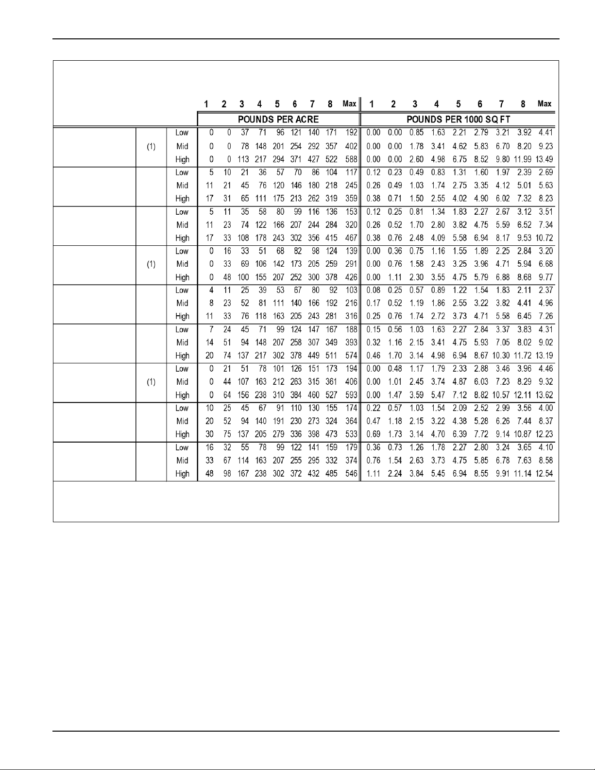
NOTES:
(1) Low germination may occur due to shallow seeding depth for this seed.
Seed
Fescue,Tall
Millet
Oats
Ryegrass
Sorghum Sudan
Soybeans
Turn ips
Purple Top
Wheat, Winter
INDICATOR SETTINGS INDICATOR SETTINGS
NOTES
RANGE
Corn, (Bin Run)
Figure 2-5: Front Seedbox Seed Chart (2 of 2)
2-5
Page 20
OPERATION
12345678Max 1 2 345678Max
135710121517190.020.070.120.170.220.270.340.390.44
146911141719220.030.080.140.200.260.330.390.440.50
135810121517190.030.070.120.180.230.280.340.390.44
136911131517190.020.070.150.200.250.290.340.390.44
11245688 90.010.030.060.080.110.130.150.180.20
146810131517190.030.080.140.180.240.300.340.390.43
246912141719220.040.100.150.210.270.330.390.440.50
124567810110.020.060.080.120.140.160.190.220.25e135810121517190.030.070.120.180.230.280.340.390.44
2 4 7 10 12 14 17 20 22 0.04 0.10 0.16 0.22 0.28 0.33 0.40 0.46 0.51
135710121416190.020.070.120.170.220.280.330.380.43
12579111315170.020.070.120.160.210.260.300.350.39
POUNDS PER ACRE POUNDS PER 1000 SQ FT
Rear Seedbox Seed Chart
Rear Box 4C589 Seed Meters. Standard on the BPSB-6.
tipede
ssica
dsfoot Trefoil
DICATOR SETTINGS
alfa
Figure 2-6: Rear Seedbox Seed Chart
2-6 3P091
ver, Alsike
ver, Red
icory, Forage
tuce
nips
itchgrass
rghum / Sudan Grass
Page 21
OPERATION
Sprocket Storage
Remove Klik Pin
to change Sprocket
Low-Range 10 Tooth
Mid-Range 13 Tooth
High-Range 19 Tooth
Driver Sprocket
Remove Klik Pin
to change Sprocket
Low-Range 37 Tooth
Mid-Range 23 Tooth
High-Range 23 Tooth
Driven Sprocket
Engage Position
Disengaged Position
Klik Pin
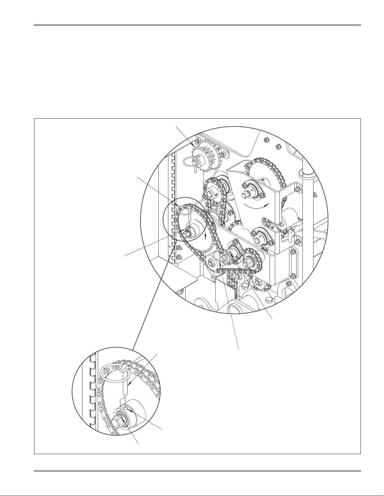
Seed Rate
Refer to Seed Chart on the Front Seedbox Cover to
determine range for Seeding Rate. It should be used as a
general guide only, because of seed size variation and
cleanliness. A more accurate Seed Rate can be
determined by Calibrating the Seeder, see Seed Rate
Calibration in this section.
• To install sprockets for the required range, remove the
Klik Pin and change the Driver and Driven Sprockets
accordingly. Also, refer to decal on the inside of the
Transmission Cover.
Disengage or Engage Seeding:
• To disengage seeding, remove Klik Pin and store it in
the hole provided in the end of the shaft.
• To engage seeding, re-install the Klik Pin into the
sprocket and shaft.
Figure 2-7: Seed Rate
2-7
Page 22
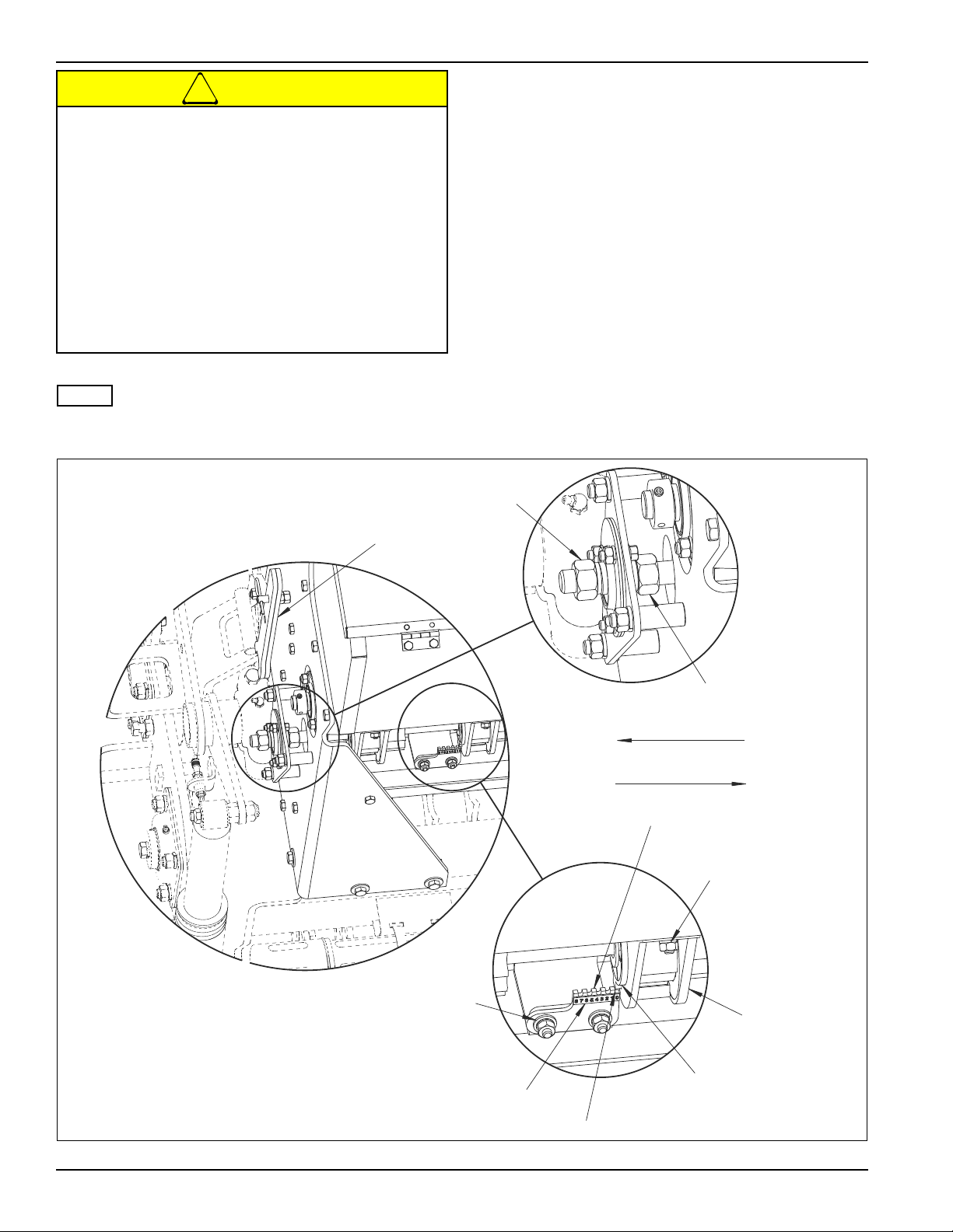
OPERATION
CAUTION
NOTE
Shaft moves to increase seed rate
Shaft moves to decrease seed rate
Wrenches
Outer Seed Rate
Adjusting Nut
Inner Seed Rate
Adjusting Nut
Seed Cup Mounting
Hardware
Indicator
Large
Seed Cup
Seed Cup
Cut-off
Indicator Mounting
Hardware
Indicator Scale
Indicator must read "0"
when Seed Cups are closed
To prevent damage to seed meters, do not apply
excessive force to adjusting nuts. This is
especially important when closing meters as
seed in flutes can be pinched between seed cup
cutoff and washer.
Do not close meters more than 1/8" when there is
seed in the meters without rotating the seed shaft
to prevent damage to the rotating washers and
retainer rings in the seed meters.
Do not attempt to open meters more than 1".
(feed rolls could become disengaged from the
seed cup washer.)
Front Seedbox Seed Cups discharge to the front of the
machine.
• All cups must be set the same to seed uniformly.
Check by using the wrenches provided and loosening
the Inner Adjusting Nut and turning the Outer Seed
Rate Adjusting Nut so that the Seed Cups close.
• All cups should be completely closed. If not, individual
cups can be adjusted by loosening their mounting
bolts, moving the cups, and then re-tightening.
• With Seed Cups completely closed, Indicator edge
marked "0" should align with Seed Cup Cut-off end. If
it does not, loosen Indicator mounting hardware and
adjust it until it does. Re-tighten.
• Use Seed Chart located inside Seedbox Cover as a
guide, increase or decrease the Seed Rate by using
the wrenches provided and loosening the Inner
Adjusting Nut and turning the Outer Seed Rate
Adjusting Nut to the desired number setting on
Indicator. Re-tighten the Inner Nut.
Figure 2-8: Front Seedbox Cups
2-8 3P091
Page 23
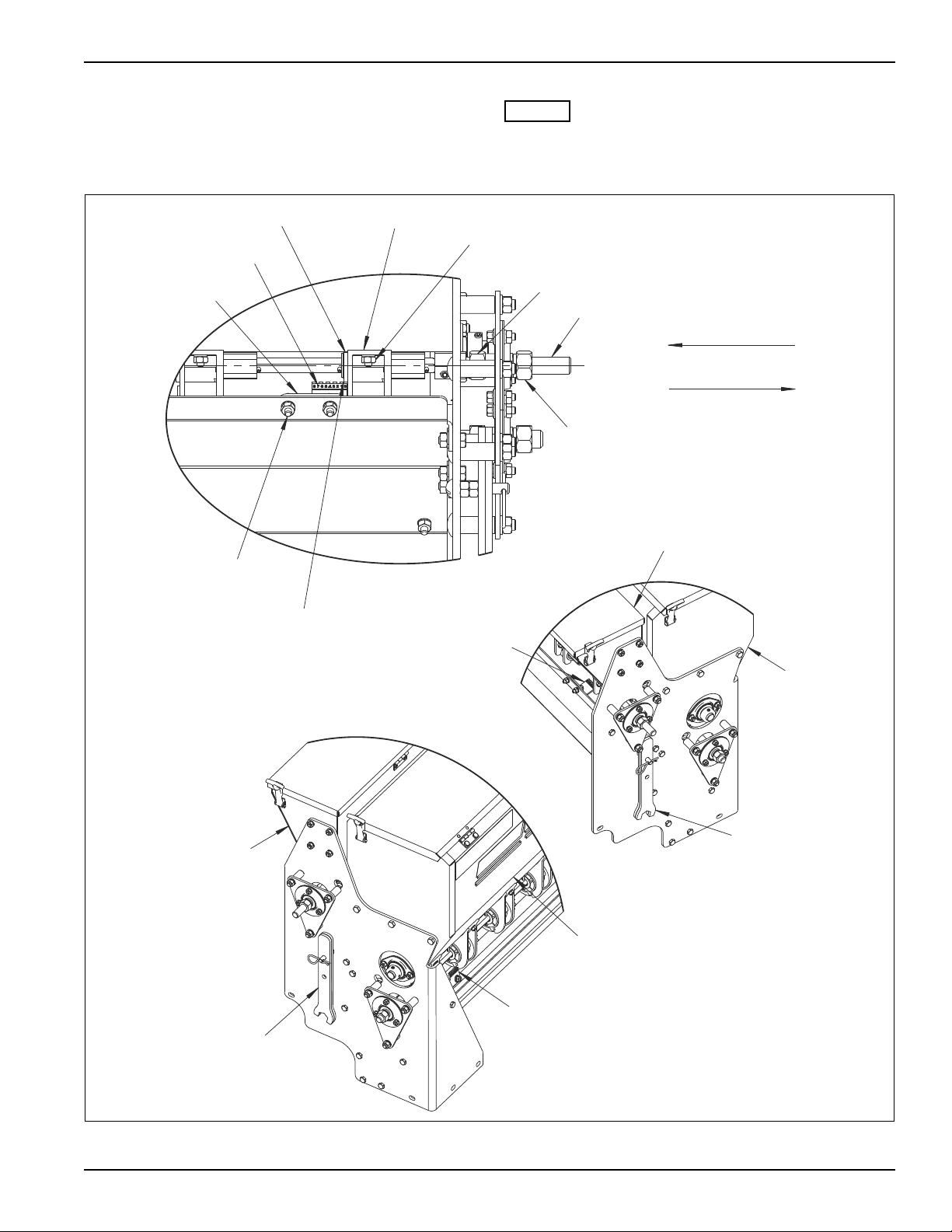
Rear Seedbox
NOTES
Outer Seed Rate
Adjusting Nut
Inner Seed Rate
Adjusting Nut
Seed Shaft
Indicator
Indicator Scale
Seed Cup
Cut-off
Indicator
Mounting Hardware
Seed Cup Mounting
Hardware
Indicator must read "0"
when Seed Cups are closed
Small Seed Cup
Shaft moves to increase Seed Rate
Shaft moves to decrease Seed Rate
Rear Seedbox
Front
Seedbox
Front Box
Indicator
Wrenches
Rear Seedbox
Front
Seedbox
Rear Box
Indicator
Wrenches
OPERATION
• Rear Seedbox cups are adjusted just like the Front
Seedbox.
Rear Seedbox Seed Cups discharge to the rear of the
machine.
Figure 2-9: Rear Seedbox Cups
2-9
Page 24
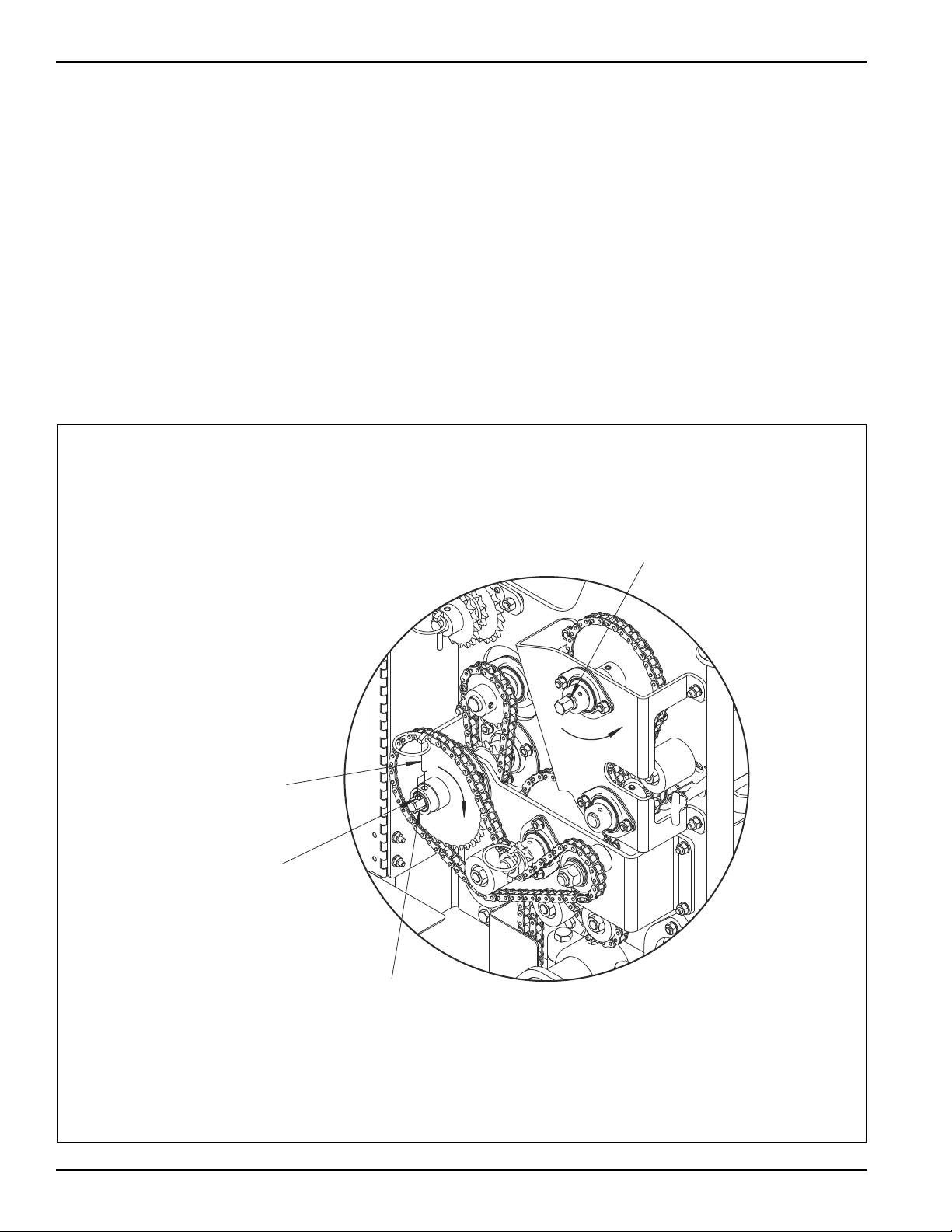
OPERATION
Front Box
5/8" Hex Turn CW
Remove Klik Pin to disengage
Front Box Drive
Rear Box 5/8" Hex
Turn CCW
Storage hole for
Klik Pin
Seed Rate Calibration
Place Calibration Trough in Collection Position by
removing (6) six Carriage Bolts. See Figure 2-11. Place
tarp under front of machine. Refer to Seed Charts on the
Seedbox Covers to determine initial Seed Meter Settings.
If you need to close Seed Meters more than 1/8" for
reduced output when there is seed in the Meters, you
must turn the Seed Shaft while making the adjustment to
prevent damage to the rotating washers and retainer
rings in the Seed Meters.
Front Seedbox
1. Identify lowest Transmission Range expected to
achieve Seed Rate.
2. Adjust Seed Meter Setting.
3. Remove Seed Drive Disconnect Pin - Front Box.
4. Prime Meters: Turn 5/8" Hex for Front Box Calibration
CW (Clockwise) until all Meters are discharging
seed. Empty Calibration Trough or Tarp.
5. Turn the 5/8" Hex CW 252 (low range), 528 (mid
range) or 771 (high range) revolutions to meter out
seed.
6. Weigh the seed = Lbs / Acre.
7. Adjust Meters and Re-Calibrate as necessary.
8. Ensure Transmission is set-up for proper Seeding
Range.
9. Re-Install Seed Drive Disconnect Pin - Front Box.
10. Re-Install Calibration Trough in Seeding Position.
Figure 2-10: Front Seedbox Calibration
2-10 3P091
Page 25
OPERATION
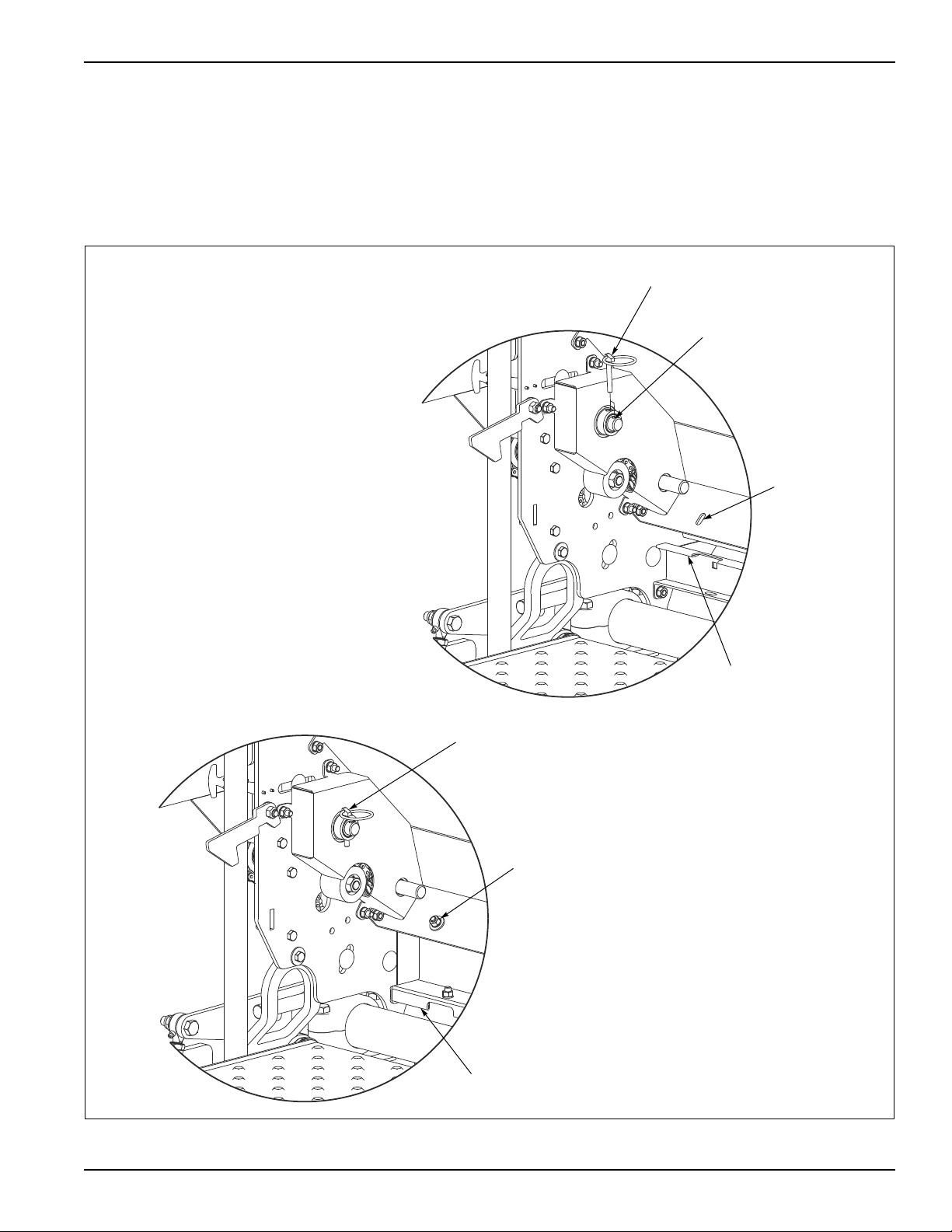
Trough in
Collection Position
Remove Klik Pin to disengage
Rear Box Drive
Storage hole for
Klik Pin
Installed Klik Pin to engage
Rear Box Drive
Trough in
Seeding Position
Trough
Hardware
Removed
(6) 5/16-18 x 3/4 Carriage Bolts
and Hardware
Rear Seedbox
1. Adjust Seed Meter Setting.
2. Remove Seed Drive Disconnect Pin - Rear Box.
3. Prime Meters: Turn 5/8" Hex for Rear Box Calibration
CCW (Counter Clockwise) until all Meters are
discharging seed. Empty Calibration Trough or Tarp.
4. Turn the 5/8" Hex CCW 143 revolutions to meter out
seed.
5. Weigh the seed = Lbs / Acre.
6. Adjust Meters and Re-Calibrate as necessary.
7. Re-Install Seed Drive Disconnect Pin - Rear Box.
8. Re-Install Calibration Trough in Seeding Position.
Figure 2-11: Rear Seedbox Calibration
2-11
Page 26
OPERATION
DANGER
Engage Position
Disengaged position
Klik Pin
Gage Wheel
on each side
Keep riders off of machinery
Do not allow anyone to ride on tractor or
machine. Riders could be struck by foreign
objects or thrown from the machine.
Never allow children to operate equipment.
Keep bystanders away from machine during
operation.
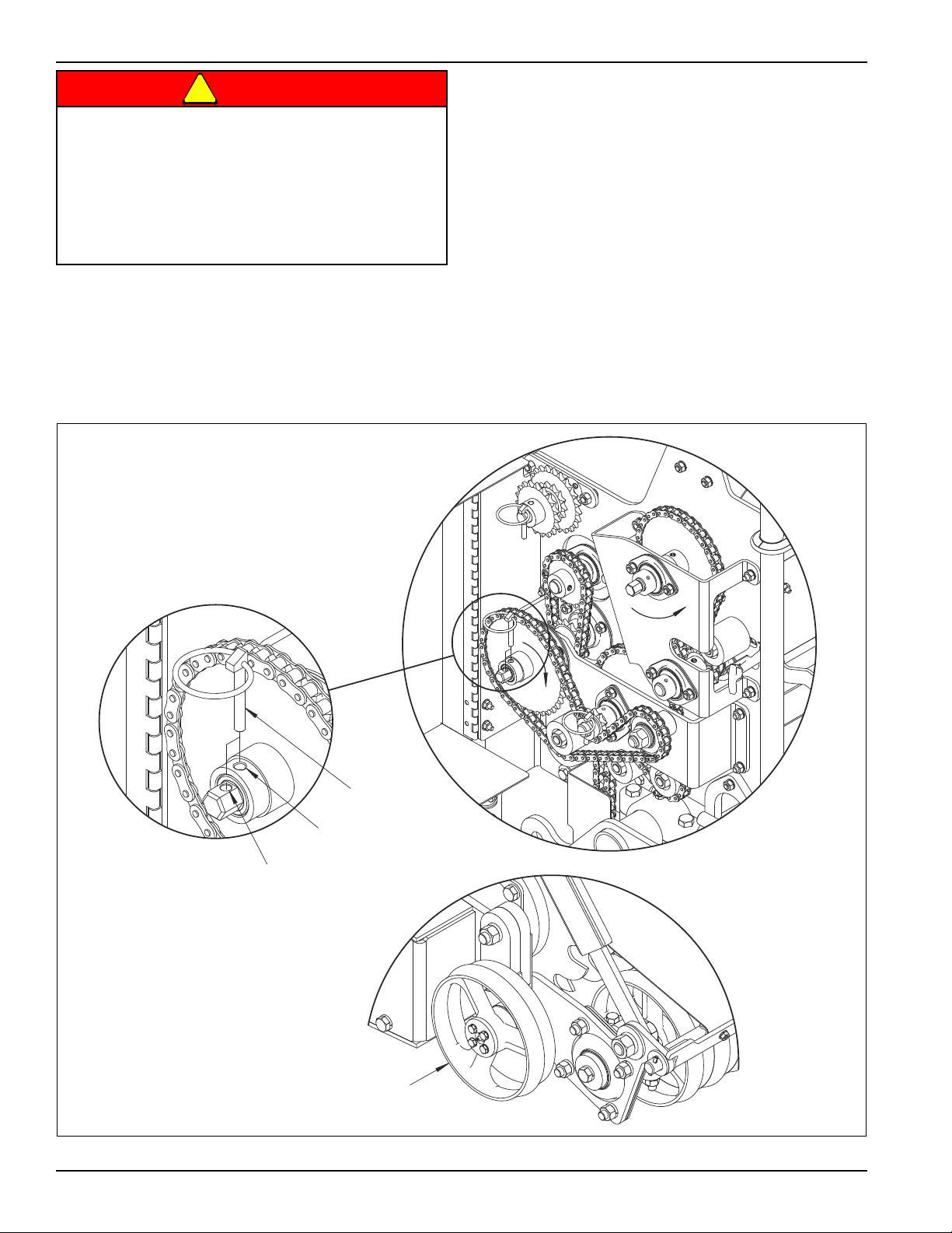
Seeding
• Planting speeds of 4-8 mph typically works best.
Adjust speed to conditions.
• Planting in two passes at 90 degrees to each other is
also, a effective method for an even stand.
Make sure you cut the seeding rate in half when planting
in two passes.
• In most conditions, a single pass will be sufficient. If
conditions dictate, two or more tillage passes may be
done. Disengage Seed Meters by removing the seed
drive disconnect Klik Pin from the transmission and
storing it in the hole provided in the end of the shaft.
Once the soil is tilled sufficiently, engage seeding by
re-installing the seed drive disconnect Klik Pin into
sprocket and shaft to seed on the next pass.
• If very small seeds are being planted that need to be
very shallow or on the surface, use the gage wheels to
raise the tillage rotor partially or entirely out of the
ground for the final pass.
• Always raise the seeder out of the ground for sharp
turns.
Figure 2-12: Seeding
2-12 3P091
Page 27
DANGER
Wear Protective Gloves And Safety Glasses Or
Air Shock
Drive Rotor
Tillage Rotor
Valve Stem
Goggles When Working With Air Shock.
Pressurized Air Shock May Violently Extend If
Disconnected From Machine Without Releasing
Its Air Pressure Prior To Removing.
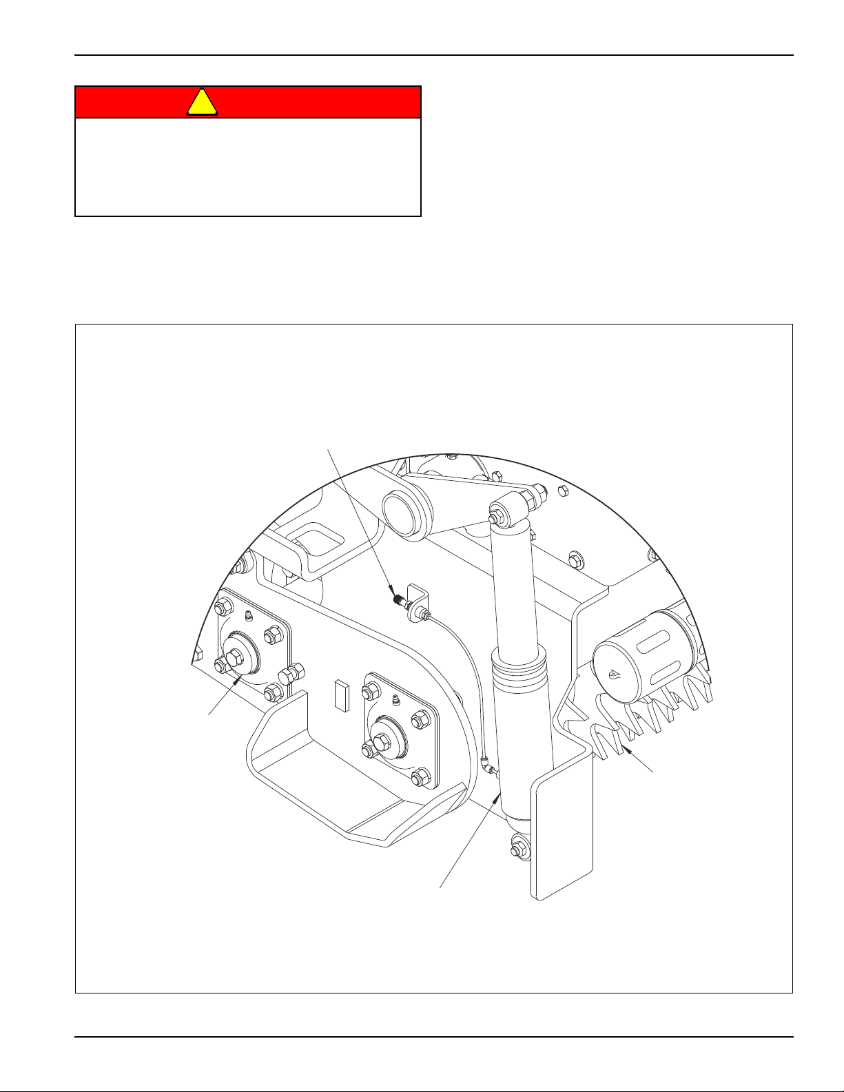
Air Shock
• Check and adjust air pressure while machine is resting
on the ground.
OPERATION
• Typical air pressure range for this Implement is 20-100
psi. In some instances more air pressure maybe
necessary, but do not exceed 120psi. Optimal air
pressure will vary depending soil conditions.
• Lower air pressure on soft ground and higher air
pressure on hard ground works best.
• Increasing air pressure transfers machine weight from
the Drive Rotor to the Tillage Rotor, resulting in more
aggressive tillage action. However, excessive air
pressure will cause the Drive Rotor to lose traction,
resulting in poor tillage performance by the Tillage
Rotor.
Figure 2-13: Air Shock
2-13
Page 28
OPERATION
Gage Wheel
Left side
Tillage Rotor
Step Must Be Raised
During Operation
Gage Wheel
Right side
Tillage Rotor
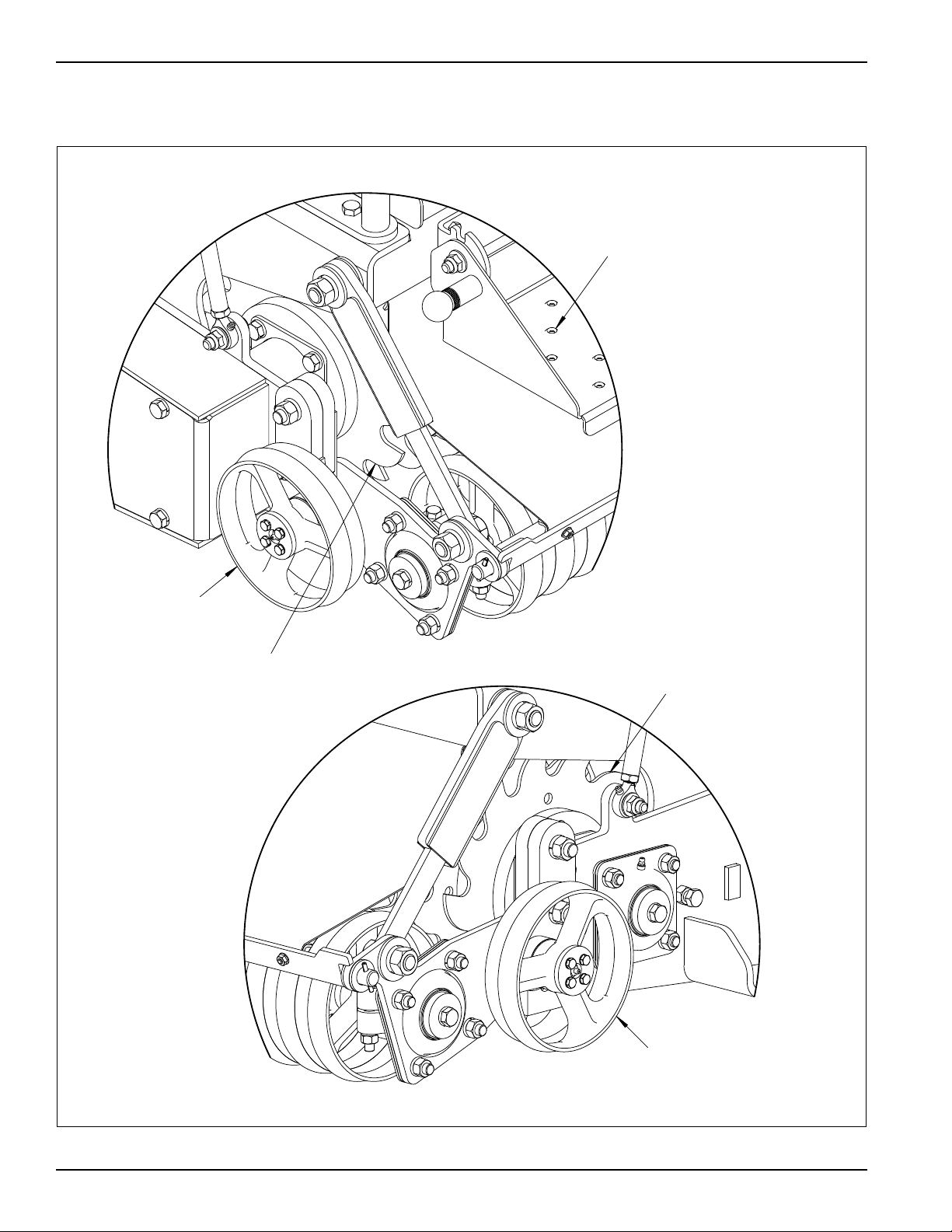
Gage Wheels
• Gage Wheels control the depth of the Tillage Rotor.
• Engaging the Gage Wheels with the ground will also
help reduce Tillage Rotor bounce.
Figure 2-14: Gage Wheels
2-14 3P091
Page 29
OPERATION
Front
Adjusting
Bolt
Jam Nut
Lower Frame
Side Plate
Thrust Guide
1/32” MAX
Thrust Guide
Adjusting Bolt
Front
Jam Nut
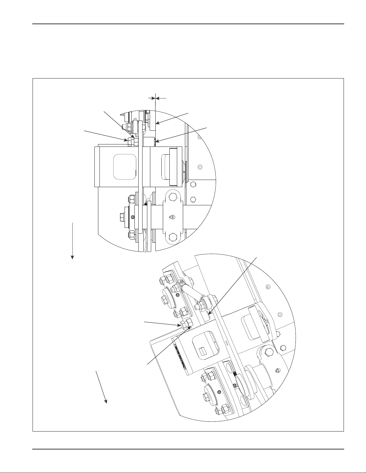
Rotor Thrust Guide
• Thrust Guide on each side of the machine, should
have 1/32" maximum clearance between Guide and
Lower Frame Side Plates.
• If adjustment is needed loosen Jam Nut and turn
Adjusting Bolt, Re-tighten Jam Nut.
Right side of the machine shown.
Figure 2-15: Rotor Thrust Guide
2-15
Page 30
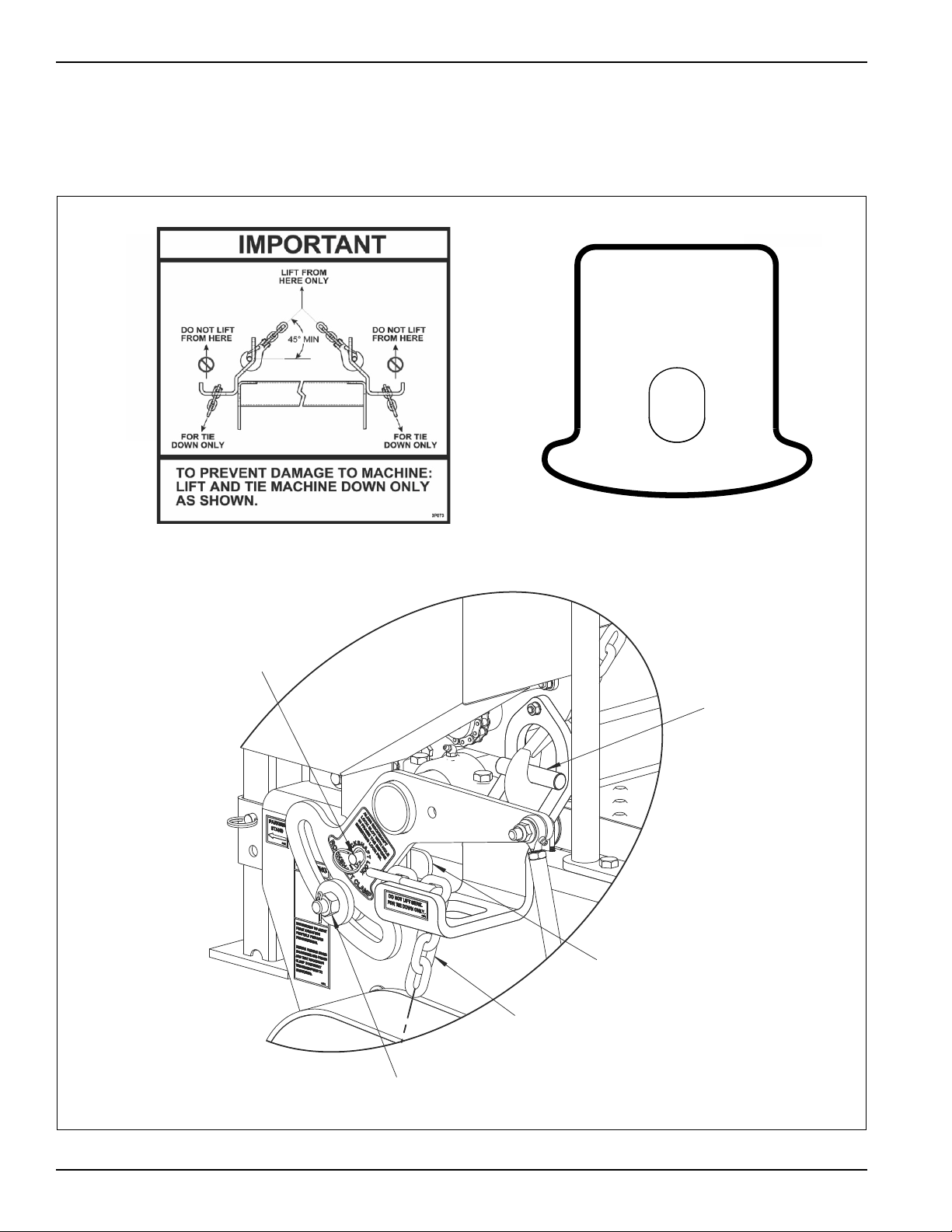
OPERATION
Insert Rockshaft
Lock Detent Pin
into frame tab
Tighten Rockshaft
Clamp Nut to prevent
movement
Frame Tab
Hook Lift Strap or
Chain Here
Tie-Down Strap
or Chain Here
ALIGN ROCKSHAFT
LOCK SLOT WITH HOLE
IN FRAME TAB BEFORE
INSERTING LOCK PIN.
3P075
R
O
C
K
S
H
A
F
T
L
M
P
R
O
C
K
S
H
A
F
T
L
O
C
K
C
A
Lift and Tie-Down
• Before loading Implement onto a trailer and detaching
from tractor, lower machine to the ground and install
Rockshaft Lock Detent Pin when Rockshaft Lock Slot
aligns with Frame Tab Hole.
• Tighten nut on Rockshaft Clamp to prevent movement.
• Before lifting Implement Open Rear Seedbox Cover to
prevent possible damage during lifting. Tie machine
down on the trailer and close Rear Seedbox Cover.
Refer to decals.
Figure 2-16: Lift and Tie-Down
2-16 3P091
Page 31
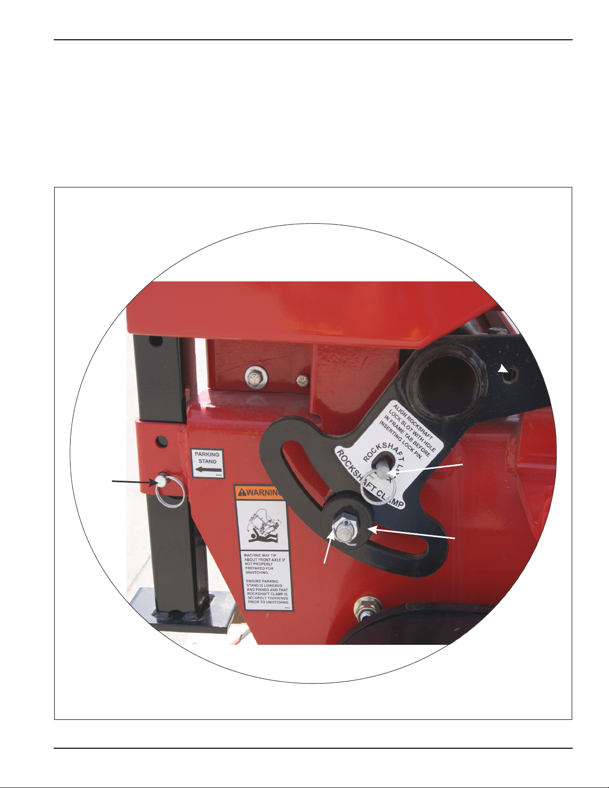
OPERATION
Stand Pin
Insert Rockshaft
Lock Detent Pin
Rockshaft Clamp
Tighten Rockshaft
Clamp Nut enough
to prevent movement
Storage
• At the end of the season, empty Seedboxes and Seed
Meters before cleaning your machine for storage.
• Avoid spraying high pressure washer directly at
bearing seals.
• Grease machine after washing to displace any
residual water.
• Repaint areas where paint has worn off.
• Repair or replace any broken or damaged parts.
• Store in a dry, protected place.
• Before detaching implement from tractor, lower
machine to the ground and tighten nut on Rockshaft
Clamp to prevent movement.
• Install Rockshaft Lock Detent Pin if Rockshaft Lock
Slot aligns with Frame Tab Hole. Lower stand.
Figure 2-17: Storage
2-17
Page 32

OPERATION
Page Intentionally Blank
2-18 3P091
Page 33
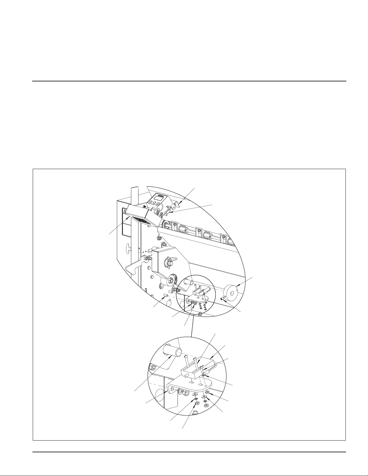
Chapter 3
HHCS,3/8-16 x 1
Lock Washer,3/8
Nut,Hex 3/8-16
Acre Meter
Assembly
Acre Meter Bracket
Magnet Wheel
Magnet Wheel
Set Screw
HHCS,5/16-18 x 1
Lock Washer,5/16
Nut,Hex 5/16-18
Pick-up Switch
Rnd Hd,#6-32 x 1/2
Nut,Hex #6-32
Nut,Hex #8-32
Lock Washer,#8-32
Flat Washer,#8-32
Rnd Hd,#8-32 x 1-1/4
Pick-up Switch
Bracket
Drive Shaft
Pick-up Switch
Ground Wire
Optional Equipment Instructions
Acre Meter Kit 3P099 Installation
The Acre Meter Kit consists of four main parts; Acre
Meter Assembly, Pick-up Switch Bracket, Pick-up Switch,
and Magnet Wheel.
1. Remove 3/8-16 Hardware from Acre Meter
Assembly. Use the Acre Meter Bracket as a guide
and drill two 13/32" holes into the seedbox. Insert
hardware and Tighten.Attach Pick-up Switch Bracket
to the Lower Frame with 5/16-18 Hardware.
2. Attach Pick-up Switch to Bracket with #8-32
Hardware. Do not tighten at this time.
3. Attach ground wire with #6-32 Hardware, removing
paint under the wire connector to assure a good
electrical ground connection.
Figure 3-1: Acre Meter (1 of 2)
3-1
Page 34
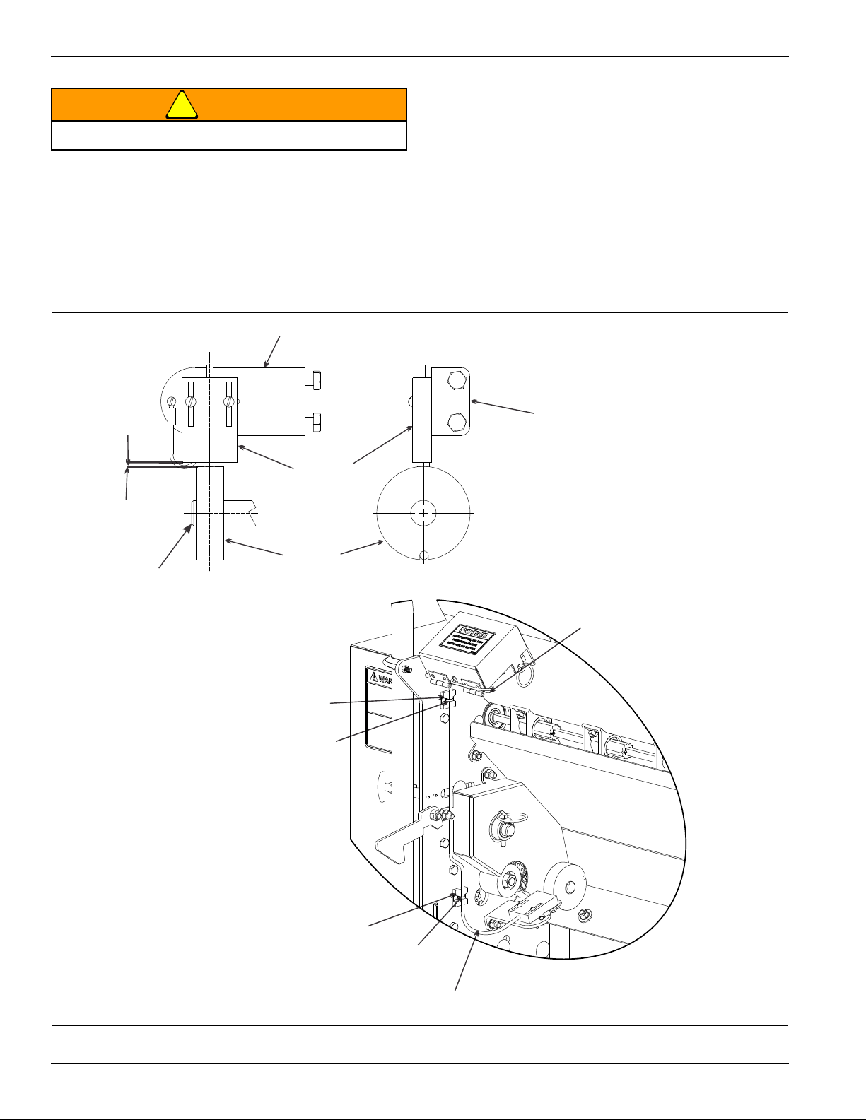
OPTIONAL EQUIPMENT INSTRUCTIONS
WARNING
H
1/8” max
Magnet
Wheel
Pick-up
Switch
Bracket
Bracket
Drive Shaft
Connect Plugs
and bundle cables
together neatly and
cable tie
Adhesive Cable
Tie Mounting
Base
Cable Tie
Adhesive Cable
Tie Mounting Base
Cable Tie
Pick-up
Switch Cable
Do Not Pressure Clean With Air Or Water.
4. Press or slide Magnet Wheel onto Drive Shaft until it
is vertically centered with the Pick-up Switch.
5. Adjust the Pick-up Switch so the centerline of Magnet
Wheel and Pick-up Switch are horizontally and
vertically aligned with a maximum 1/8" gap between
them. Firmly tighten Switch to bracket and tighten set
screw (if present) in Wheel.
Alignment of Pick-up Switch and Magnet Wheel is
critical. Improper alignment will cause the Acre Meter to
record acres erratically or not at all.
6. Route Pick-up Switch Cable up to the Acre Meter
Cable and connect mating plugs.
7. Securely fasten cable to frame using the
adhesiveCable Tie Mounting Base and Cable Ties to
prevent cable from becoming entangled or rubbing
on moving parts.
8. Program Acre Meter per the following instructions on
the next page.
3-2 3P091
Figure 3-2: Acre Meter (2 of 2)
Page 35

OPTIONAL EQUIPMENT INSTRUCTIONS
Acre Meter Operations
Settings for Loup Acre Meters After 05/15/2012
The battery operated acre counter operates in one of two
modes. In sleep mode, the display is blank, and the
counter is accumulating acres. Sleep mode will be
entered if a button is not pressed for 20 seconds. In entry
mode, the display is on, and the operator can enter
values. To get into entry mode, press the
button. If you continue to press the
acre counter will cycle through the functions that it can
perform. The LEDs above the display indicate which
function is selected.
The available functions are:
Field Acres, Total Acres, Pulses per 400 ft, Width,
Password and Low Battery
*
Field Acres
Press the */FUNC button until the “FIELD” LED is lit.
The digits indicate the acres covered since the field acre
counter was cleared.
To clear the field acre count, press the UP and DOWN
buttons simultaneously for two seconds. If a password
has been entered, you will not be able to clear the total
acre count. Field acres will count in tenths of an acre up
to 9999.9 acres.
Total Acr es
Press the */FUNC button until the “FIELD” and “TOTAL”
LEDs are lit. The digits indicate the acres covered since
the total acre counter was cleared.
To clear the total acre count, press and hold the UP and
DOWN buttons for two seconds. If a password has been
entered, you will not be able to clear the total acre count.
Total acres will count from.1 to 99999 acres.
Pulses Per 400 Feet
Press the */FUNC button until the “PULSES” LED is lit.
The number in the display indicates how many pulses are
generated for every 400 feet driven. There are two
methods to enter the pulses per 400 feet:
If you know the number, select it using the UP and
DOWN buttons. When you press the
the Acre Counter will accept the number in the display as
the new pulses per 400 feet. See Table 3-1.
/FUNC
*
/FUNC button, the
/FUNC button,
*
If you do not know the pulses per mile, press and hold the
UP and DOWN buttons until the “0000” appears in the
display. The “PULSES” LED will blink. The acre counter
is now counting shaft rotations. Enter the cab and drive
400 feet. Press the
counter. The “PULSES” LED will again blink. The number
displayed is the pulses per 400 feet. Press the
button to accept the setting. The “PULSES” LED will stop
blinking and remain on.
If a password is set, you will not be able to adjust the
pulses per mile.
/FUNC button to wake up the acre
*
/FUNC
*
Width
Press the */FUNC button until the “WIDTH” LED is lit.
The number displayed is the length of your implement in
feet.
To adjust the width, press the UP and DOWN buttons. If a
password has been entered, you will not be able to adjust
the width.
The length can be adjusted from .1 to 99.9 feet, in tenths
of a foot.
Password
The password function allows you to protect the total acre
count, pulses per 400 feet, and width settings with a
password. This stops anyone from accidentally changing
those settings. When the acre counter is shipped, the
password is disabled. You can modify the pulses per 400
feet and implement width at any time.
Press the
digits will display the word “Ent” or “dIS”.
If the display shows “dIS”: The password is disabled. The
total acre count, pulses/400 ft, width, and password
settings can be adjusted using the UP and DOWN
buttons. The password can also be changed using the
UP and DOWN buttons.
If the display shows “Ent”: You must enter your password
using the UP and DOWN buttons. When your password
is displayed, press the
password. If the password is correct, you will be able to
change the acre counter settings. The password will be
viewable until the acre counter powers down. When the
acre counter is powered up again, you will have to
re-enter the password to change settings.
If the password is not correct, you will not be able to
change the acre counter settings. When the “PA SS ”
function is selected again, “Ent” will appear in the display.
/FUNC button until the “PA SS ” LED is lit. The
*
/FUNC button to test the
*
3-3
Page 36

OPTIONAL EQUIPMENT INSTRUCTIONS
Changing The Password
Select a new password using the UP and DOWN buttons.
Press the
the display. Release the
the display is your new pass code. Make sure you record
this number. Press and hold the
word “dIS” appears in the display.
If the password is forgotten, it can be disabled by
removing the batteries. The password is intended for
rental units. It is recommended that a seal be affixed to
the rear plate of the acre counter to determine if the
settings have been tampered with.
/FUNC button until the word “SEt” appears in
*
/FUNC button. The number in
*
/FUNC button until the
*
Quick-start Settings for Loup Acre Meters Prior to 05/15/2012
• When the meter is set to “count” mode in pulses screen,
meter will register only magnetic wheel revolutions.
• The meter must be in sleep mode (blank screen) to
calculate acres or to count pulses.
• The count screen must have a value other than zero
(0000) to scroll to other modes or screens.
• To reset the FIELD ACRES screen to zero (0000), press
the up and down buttons simultaneously.
To Program Me te r
1. Press the function button to scroll to pulses screen.
2. Enter the number of pulses using the up or down
buttons for the model listed in the chart. See
Ta bl e 3 - 2.
3. Press the function button to set the pulses. (If screen
goes blank before you press the function button,
repeat steps 1 and 2).
4. Press the function button to scroll to the width
screen.
5. Enter the width of seeder using the up or down
buttons for the model listed in the chart. See
Ta bl e 3 - 2.
6. Press the function button to set the width. (If screen
goes blank before you press the function button,
repeat steps 4 and 5).
7. Press the function to scroll through the screens to
check that the correct pulses and width have been
entered.
3. Press the function button to set password; screen will
show “(set)”. Record number - it is required if you
decide to disable password.
4. Let screen go blank - password is now entered.
5. Press the function button to scroll to the password
screen it will show (ent). If the screen does not show
(ent), repeat steps 2, 3 and 4.
To Disable Password
1. Press the function button to scroll to the password
screen it will show (ent).
2. Use up or down button to enter password (number).
3. Press the function button to scroll around to pass
screen again. Number entered in step 2 will appear.
4. Press up or down button to enter 0.
5. Press the function button; (dis) will appear. Password
is now disabled.
Battery Replacement
The battery operated acre counter uses 3 AA batteries.
The batteries should last between 5 and 10 years. The
acre counter will last much longer than that. Eventually,
you will have to replace the batteries. The “BATT” LED
will light when the batteries require replacement. Remove
the acre counter from the implement and undo the 4
screws on the back of the case. This will separate the
housing from the rear plate. Replace the batteries with 3
high quality AA alkaline batteries.
This unit is dust and splash resistant, under no
circumstances should this unit be submerged in any
conductive, corrosive, or flammable liquid.
To Enter Password
1. Press the function button to scroll to password
screen.
2. Pick a numeric password and enter it by using the up
or down buttons, until your password is displayed.
3-4 3P091
Page 37

OPTIONAL EQUIPMENT INSTRUCTIONS
Table 3-1: Acre Meter Settings (After 05/15/2012)
MODEL Pulses Width
SSP T604 22 5
SSP4 SS4 44 4
SSP5 44 5
SSP6 SS6 44 6
SSP8 SS8 58 8
SSP10 SS10 58 10
SSP12 SS12 58 12
SSP108 SS108 58 8
SSP110 SS110 58 10
SSP112 SS112 58 12
SSP208 SSP2081 SS208 SS2081 58 8
SSP210 SSP2101 SS210 SS2101 58 10
SSP212 SSP2121 SS212 SS2121 58 12
SSP308 SS308 29 8
SSP310 SS310 29 10
SSP312 SS312 29 12
SLP8 SL8 314 8
SLP10 SL10 314 10
SLP12 SL12 314 12
SLP204 SLP2041 128 4
SLP206 SLP2061 128 6
SLP304 SLP3041 64 4
SLP306 SLP3061 64 6
LSP5 128 5
LSP6 128 6
LSS6 128 6
SLP208 SLP2081 SL208 SL2081 116 8
SLP210 SLP2101 SL210 SL2101 116 10
SLP212 SLP2121 SL212 SL2121 116 12
SLP308 SLP3081 SL308 SL3081 58 8
SLP310 SLP3101 SL310 SL3101 58 10
SLP312 SLP3121 SL312 SL3121 58 12
BOS4F1 BOS4S1 BOS6F1 BOS6S1 45 4
BOSB4F1 BOSB4S1 BOSB6F1 BOSB6S1 45 6
BPS6 BPSB6 51 6
GLP643 SSLP643 69 5
3-5
Page 38

OPTIONAL EQUIPMENT INSTRUCTIONS
Table 3-2: Acre Meter Settings (Prior to 05/15/2012)
MODEL Pulses Width
SSP T604 293 5
SSP4 SS4 578 4
SSP5 578 5
SSP6 SS6 578 6
SSP8 SS8 764 8
SSP10 SS10 764 10
SSP12 SS12 764 12
SSP108 SS108 760 8
SSP110 SS110 760 10
SSP112 SS112 760 12
SSP208 SSP2081 SS208 SS2081 764 8
SSP210 SSP2101 SS210 SS2101 764 10
SSP212 SSP2121 SS212 SS2121 764 12
SSP308 SS308 382 8
SSP310 SS310 382 10
SSP312 SS312 382 12
SLP8 SL8 4147 8
SLP10 SL10 4147 10
SLP12 SL12 4147 12
SLP204 SLP2041 1690 4
SLP206 SLP2061 1690 6
SLP304 SLP3041 845 4
SLP306 SLP3061 845 6
LSP5 1690 5
LSP6 1690 6
LSS6 1690 6
SLP208 SLP2081 SL208 SL2081 1528 8
SLP210 SLP2101 SL210 SL2101 1528 10
SLP212 SLP2121 SL212 SL2121 1528 12
SLP308 SLP3081 SL308 SL3081 764 8
SLP310 SLP3101 SL310 SL3101 764 10
SLP312 SLP3121 SL312 SL3121 764 12
BOS4F1 BOS4S1 BOS6F1 BOS6S1 600 4
BOSB4F1 BOSB4S1 BOSB6F1 BOSB6S1 600 6
BPS6 BPSB6 679 6
GLP643 SSLP643 917 5
3-6 3P091
Page 39
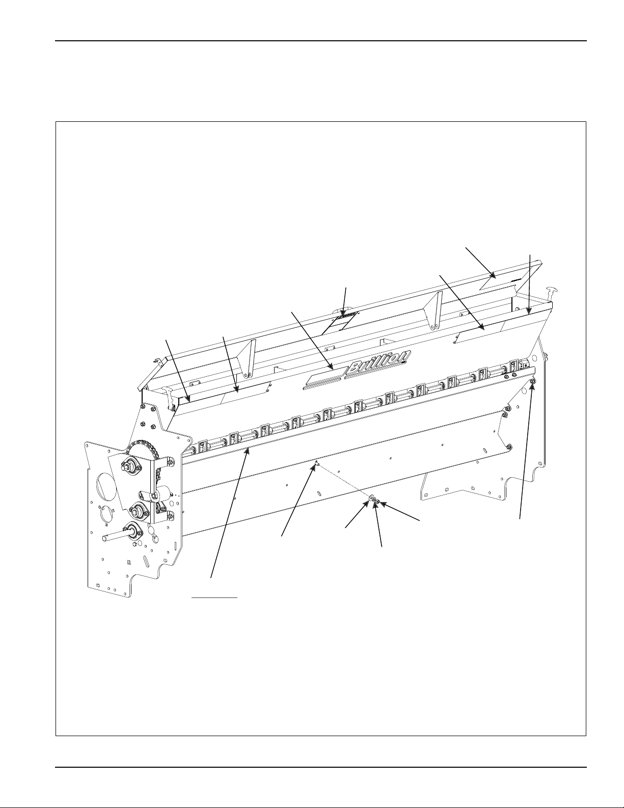
Small Seedbox Kit 3P100
Red Reflective
Decal
Red-Orange
Decal
Brillion
Decal
Warning
Decal
Red-Orange
Decal
Red Reflective
Decal
Seed
Chart
Deflector
Install first
CB,
5/16-18 x 3/4
Flat
Washer,
5/16
Lock
Washer, 5/16
Nut, Hex
5/16-18
HHCS,5/16-18 x 3/4
Lock Washer,5/16
Nut, Hex 5/16-18
• Install Small Seedbox onto Machine per the following
illustrations. Start with the Deflector.
OPTIONAL EQUIPMENT INSTRUCTIONS
Figure 3-3: Small Seedbox Kit (1 of 3)
3-7
Page 40
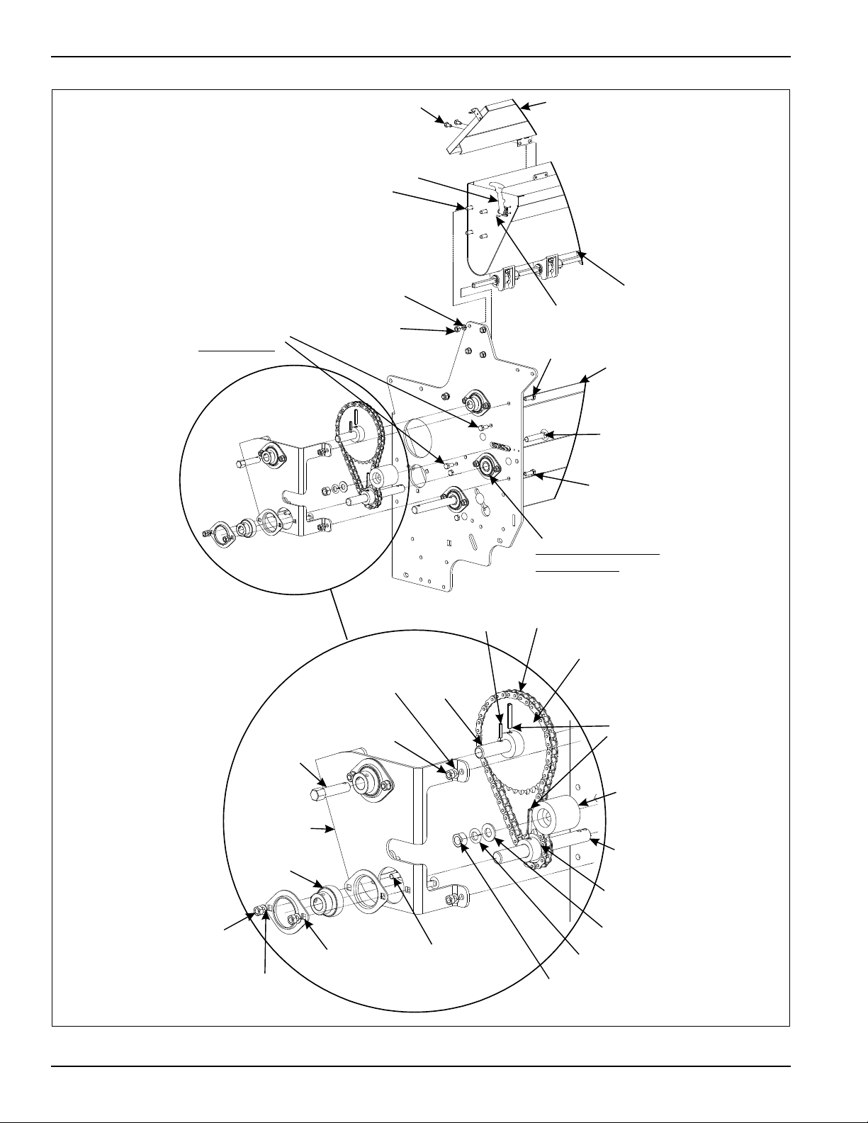
OPTIONAL EQUIPMENT INSTRUCTIONS
Cover
HHCS,1/4-20 x 1/2
Rubber Latch
HHCS,
5/16-18 x 3/4
Rivet
Small
Seedbox
HHCS,5/16-18 x 1
Deflector
CB,
1/2-13 x 2-1/2
HHCS,
5/16-18 x 1
Note Bearing Collar
opposite side
Roll Pin,3/16 x 7/8
Roller Chain, 52 Pitches
Sprocket,37T
Roll Pin,
1/4 x 1-1/2
Drive
Tube
Lock
Washer,
5/16
Idler, 2 x 2
Drive Shaft
3/4 x 7-1/2
Sprocket,13T
Flat Washer
1/2 SAE
Lock
Washer,1/2
Nut,Hex
1/2- 13
CB,
5/16-18 x 3/4
Flangette
Half,2 Bolt
Lock
Washer,5/16
Nut,Hex
5/16-18
Bearing,
3/4 Bore
Bracket
Calibration
Shaft
Nut,Hex
5/16-18
Lock Washer,
5/16
Nut,Hex
5/16-18
HHCS,5/16-18
for Deflector
x 3/4
3-8 3P091
Figure 3-4: Small Seedbox Kit (2 of 3)
Page 41
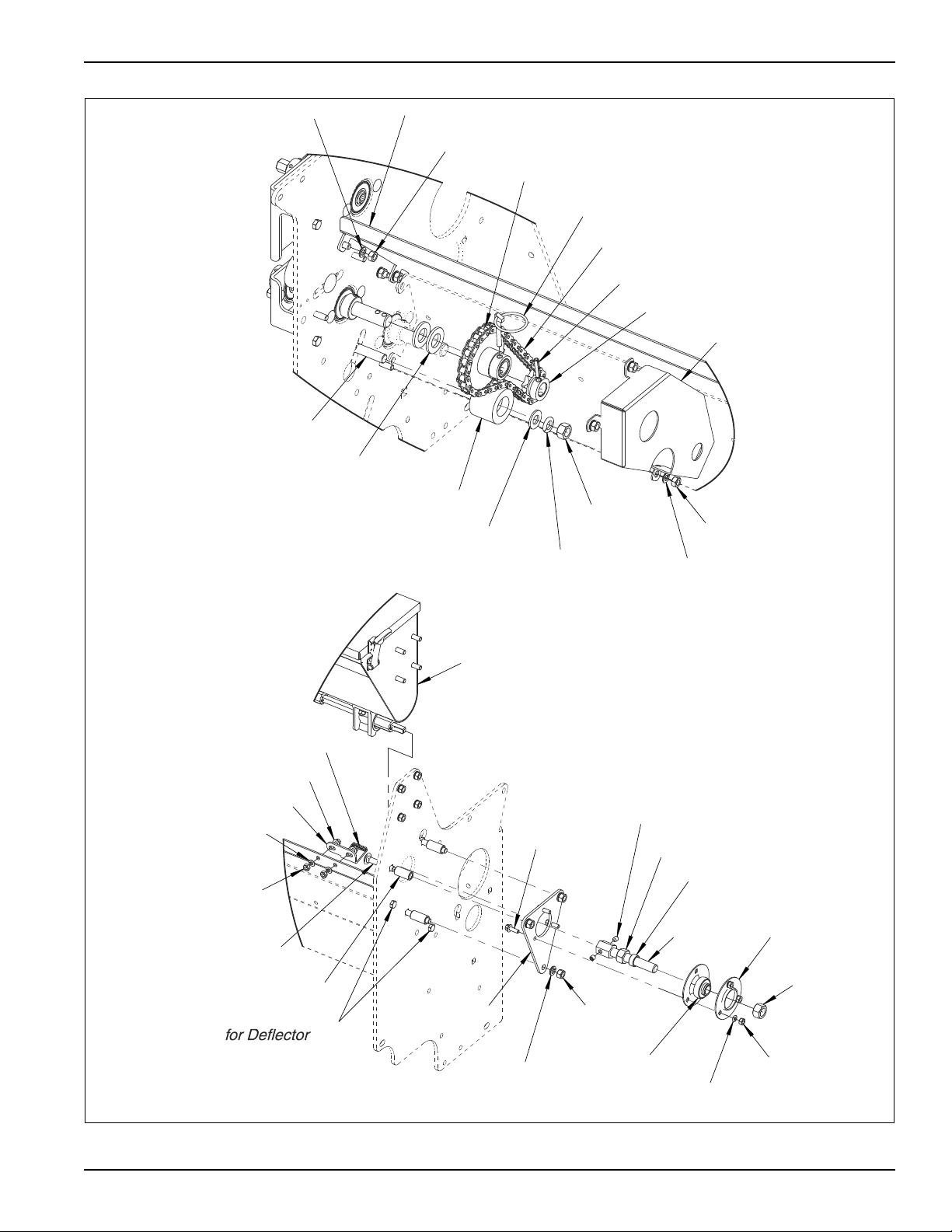
OPTIONAL EQUIPMENT INSTRUCTIONS
Small Seedbox
Indicator Decal
FHHCS,1/4-20 x 3/4
CB,3/8-16 x 2-1/4
Spacer,5/8 x 1-1/4
Indicator
Nut,Hex 1/4-20
Lock Washer,1/4
Nut,Hex
5/8-11
Nut,Hex 5/8-11
Nut,Hex
1/4-20
Lock
Washer,1/4
Lock
Washer,3/8
Nut,Hex
3/8-16
Flangette
Half,3 Bolt
Bearing,
5/8 Bore
FHHCS,
1/4-20 x 3/4
Shaft
Extension
Spacer,27/32 x 3/8
Set Screw,5/16-18 x 3/8
Bearing Plate
HHCS,5/16-18 x 3/4
Back Guard
Nut,Hex
5/16-18
Lock
Washer,5/16
Lock
Washer,1/2
Nut,Hex
1/2-13
Idler,2 x 1-1/2
Flat Washer,
1/2 SAE
CB,1/2-13 x 2
Roll Pin,1/4 x 1-1/4
Sprocket,10T
Klik-Pin
Roller Chain,42 Pitches
Sprocket,23T
Flat Washer,3/4 SAE
Nut,Hex 5/16-18
Lock
Washer,5/16
Deflector
Figure 3-5: Small Seedbox Kit (3 of 3)
3-9
Page 42

OPTIONAL EQUIPMENT INSTRUCTIONS
Table provided for general use.
NOTES:
3-10 3P091
Page 43
Chapter 4
Maintenance
Fasteners
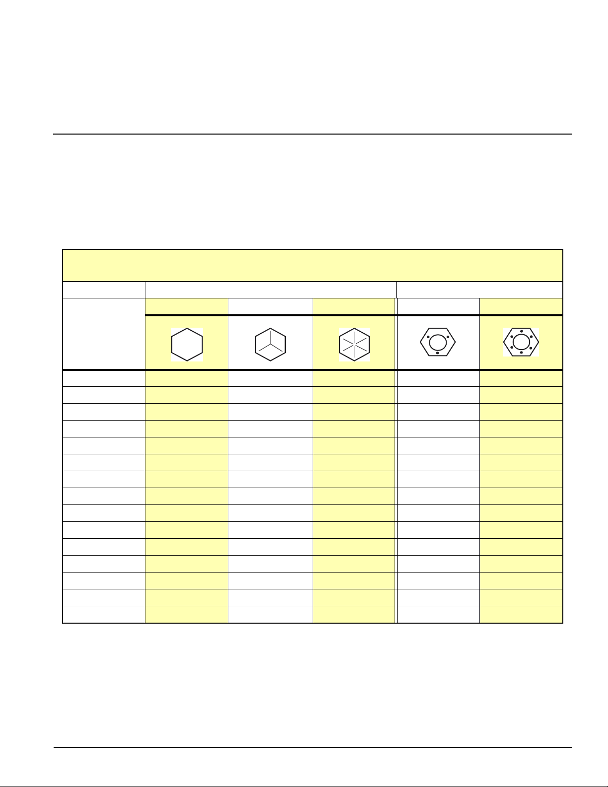
Before operating your Brillion machine, check all
hardware for tightness. Use the Tightening Torque Table
reproduced below as a guide. See Table 4-1.
Table 4-1: Torque Tightening Table
BOLT/NUT TIGHTENING TORQUES
For Fine Threads Multiply Chart Values by 1.1
Thread Size Bolt Grade Plated, Stover Lock Nuts
GRADE 2 GRADE 5 GRADE 8 GRADE B GRADE C
Figure4-1
1/4-20
5/16-18
3/8-16
7/16-14
58 12 5/7 7/10
11 17 24 10/12 11/16
20 30 45 15/20 20/28
30 50 70 23/32 31/43
• After a few hours of use, check entire machine and
tighten any loose nuts or bolts. Daily or periodic
checks should be made thereafter.
MIN/MAX MIN/MAX
1/2-13
9/16-12
5/8-11
3/4-10
7/8-9
1-8
1 1/8-7 355 795 1290
1 1/4-7 500 1120 1820
1 3/8-6 745 1670 2710
1 1/2-6 870 1950 3160
• Values are given in foot-pounds.
• Use GRADE B lock nuts with GRADE 2 and GRADE 5
bolts only.
• Use GRADE C lock nuts with GRADE 8 bolts only.
50 75 105 37/50 45/62
70 110 155 50/70 70/95
100 150 210 70/95 90/122
170 270 375 125/165 155/210
165 430 610 275/375 360/462
250 645 910
4-1
Page 44
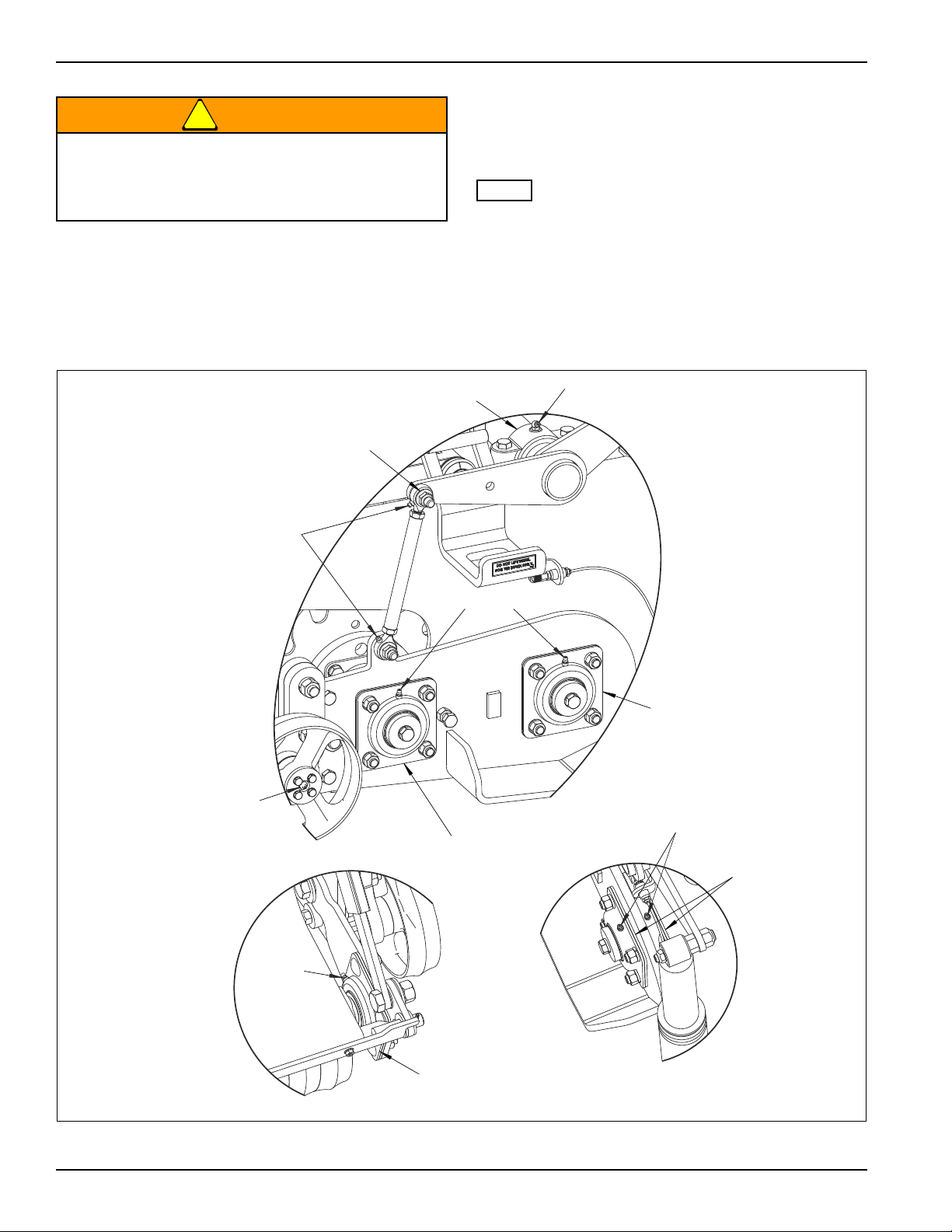
MAINTENANCE
WARNING
NOTE
8 Hrs
8 Hrs
25 Hrs
8 Hrs
Tillage Rotor
Bearing
Drive Rotor
Bearing
Rockshaft
Bearing
Rockshaft
Link
25 Hrs
Firming Roller
Bearing
25 Hrs
Tillage Rotor
Bearing
Do Not Lubricate Machine While Machine Is In
Motion. If Any Guards Are Removed For
Lubricating, They Must Be Replaced Before
Operating.
Lubrication
• Grease per recommended lubrication frequency
intervals indicated or if machine is not to be used for
some time. Greaseable components are the same on
each side, right side shown.
• Lubricate Roller Chains periodically with quality chain
oil.
For best penetration, lubricate chain immediately after
use while chain is still warm.
It is good machine maintenance practice to check all
bolts for tightness during regular lubrications. Tighten any
fasteners that may have loosened during operation.
Figure 4-2: Lubrication (1 of 2)
4-2 3P091
Page 45
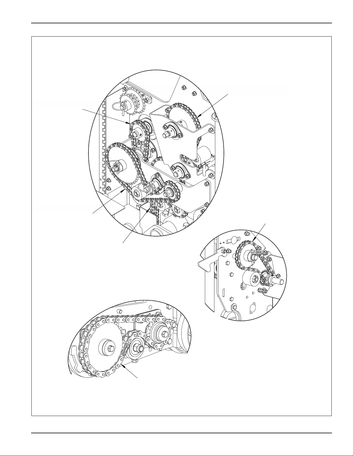
#80 Rotor Drive Chain
#40 Primary
Drive Chain
#40 Agitator
Chain
#40 Seedbox
Drive Chain
#40 Small Seedbox
Drive Chain
#40 Small Seedbox
back Drive Chain
MAINTENANCE
Figure 4-3: Lubrication (2 of 2)
4-3
Page 46
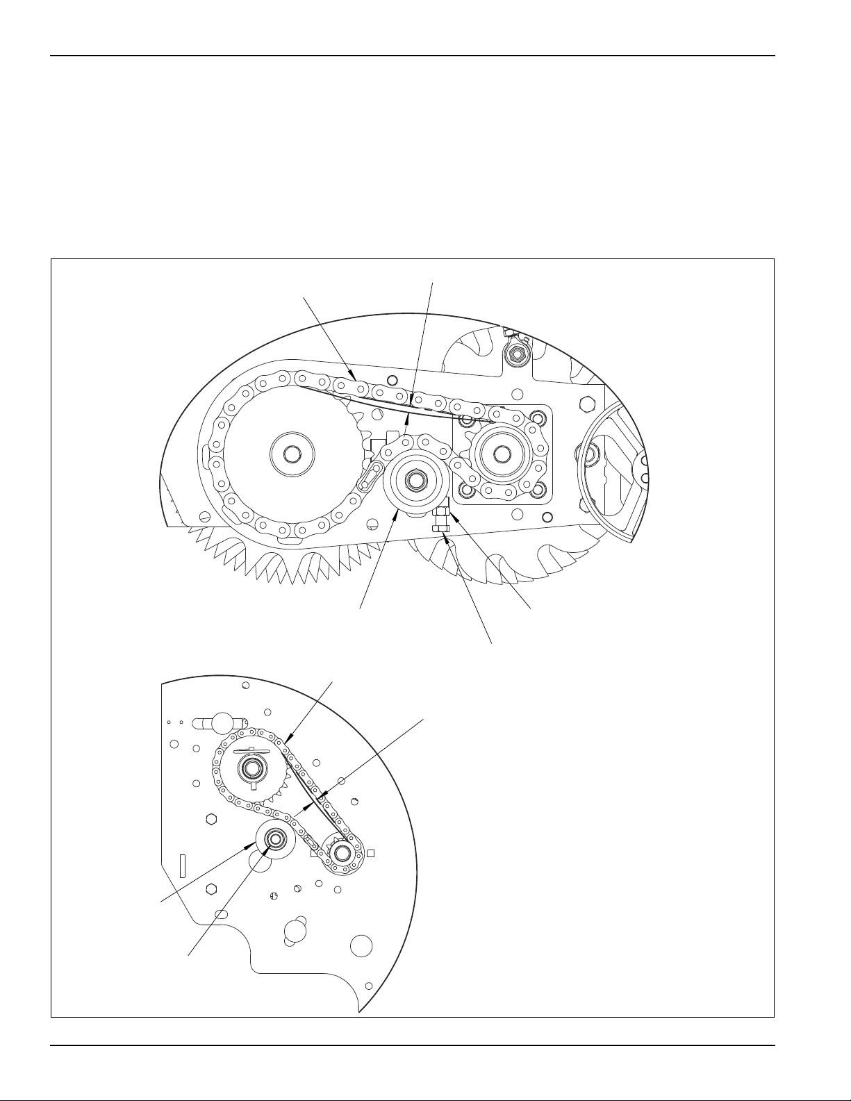
MAINTENANCE
1/4" - 5/16" Deflection
#80 Rotor Drive Chain
Loosen Hex Nut
Turn Adjustment Bolt
Idler
1/8" - 3/16" Deflection
#40 Small Seedbox
back Drive Chain
Slide Idler
Loosen Hex Nut
Chain Tension
• The Rotor Drive Chain is properly adjusted when it has
a 1/4" - 5/16" deflection across the top of the
sprockets, while the bottom is tight. If adjustment is
needed loosen the Hex Nut and turn the Adjustment
Bolt until the proper deflection is achieved.
• The Idler is specially designed so that if the Idler is
unable to achieve the 1/4"-5/16" chain deflection, the
chain is worn out and needs to be replaced.
• The Small Seedbox back Drive Chain is properly
adjusted when it has 1/8” - 3/16” deflection across the
sprockets.
• If adjustment is needed loosen the Hex Nut on the
Idler and slide the Idler until the proper deflection is
achieved.
Figure 4-4: Chain Tension (1 of 2)
4-4 3P091
Page 47
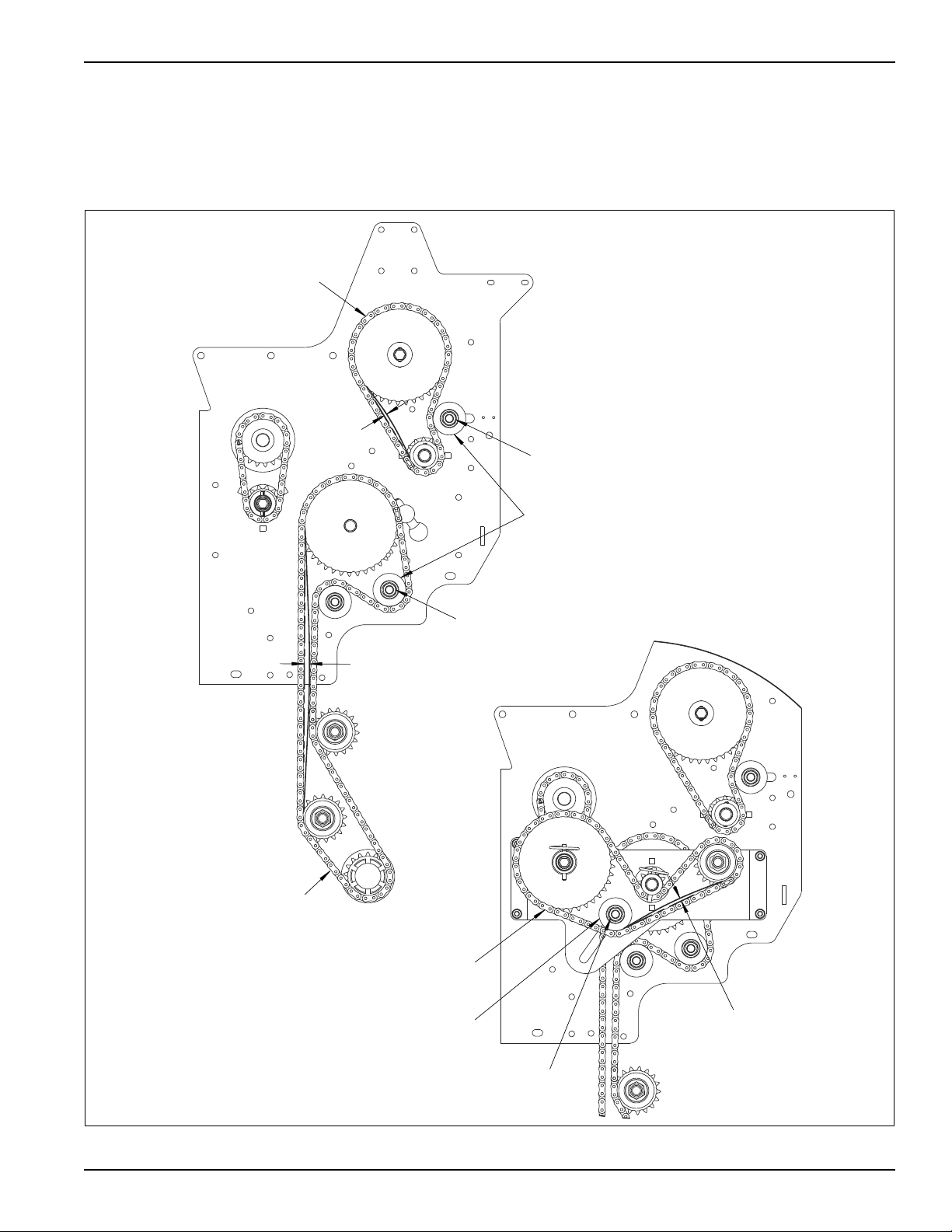
MAINTENANCE
1/8" - 3/16"
Deflection
5/16" - 3/8"
Deflection
#40 Small Seedbox
Drive Chain
Slide Idler
Loosen
Hex Nut
#40 Primary
Drive Chain
1/8" - 3/16"
Deflection
#40 Seedbox
Drive Chain
Slide Idler
Loosen Hex Nut
Loosen Hex Nut
• The Small Seedbox Drive Chain and Seedbox Drive
Chain is properly adjusted when it has 1/8" - 3/16"
deflection across the sprockets.
• The Primary Drive Chain is properly adjusted at 5/16" 3/8" deflection across the sprockets.
• If adjustment is needed loosen the Hex Nut on the
Idler and slide the Idler until the proper sag is
achieved.
Figure 4-5: Chain Tension (2 of 2)
4-5
Page 48
MAINTENANCE
WARNING
Front
Adjusting
Bolt
Jam Nut
Lower Frame
Side Plate
Thrust Guide
Thrust Guide
Adjusting Bolt
Front
Jam Nut
Rotor Thrust Guide
Support machine with blocks or stands when
working on or under it to prevent injury in case of
hydraulic failure or inadvertent lowering by
another person. Make sure all moving parts have
stopped before doing any rotor maintenance.
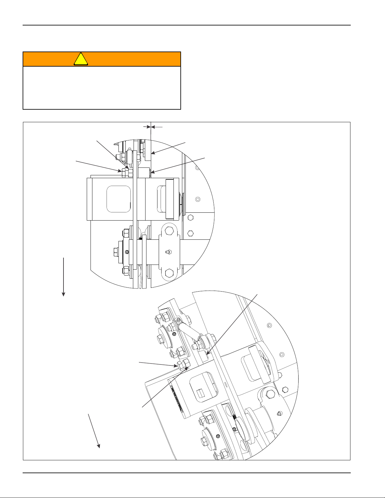
• On each side of the machine, check the 1/32”
maximum clearance between the Thrust Guide and
Lower Frame Side Plate.
• If adjustment is needed loosen Jam Nut and turn
Adjusting Bolt. Retighten Jam Nut.
Right side of the machine is shown.
Figure 4-6: Rotor Thrust Guide
4-6 3P091
Page 49
MAINTENANCE
Roll Pin
Drive Rotor
Slotted Hex Nut
Tillage Rotor
Slotted Hex Nut
Roll Pin
Firming Roller
Slide Clamp
Loosen Hex Nuts
Front
Firming Roller
Rotor Blade
Rotor Blade
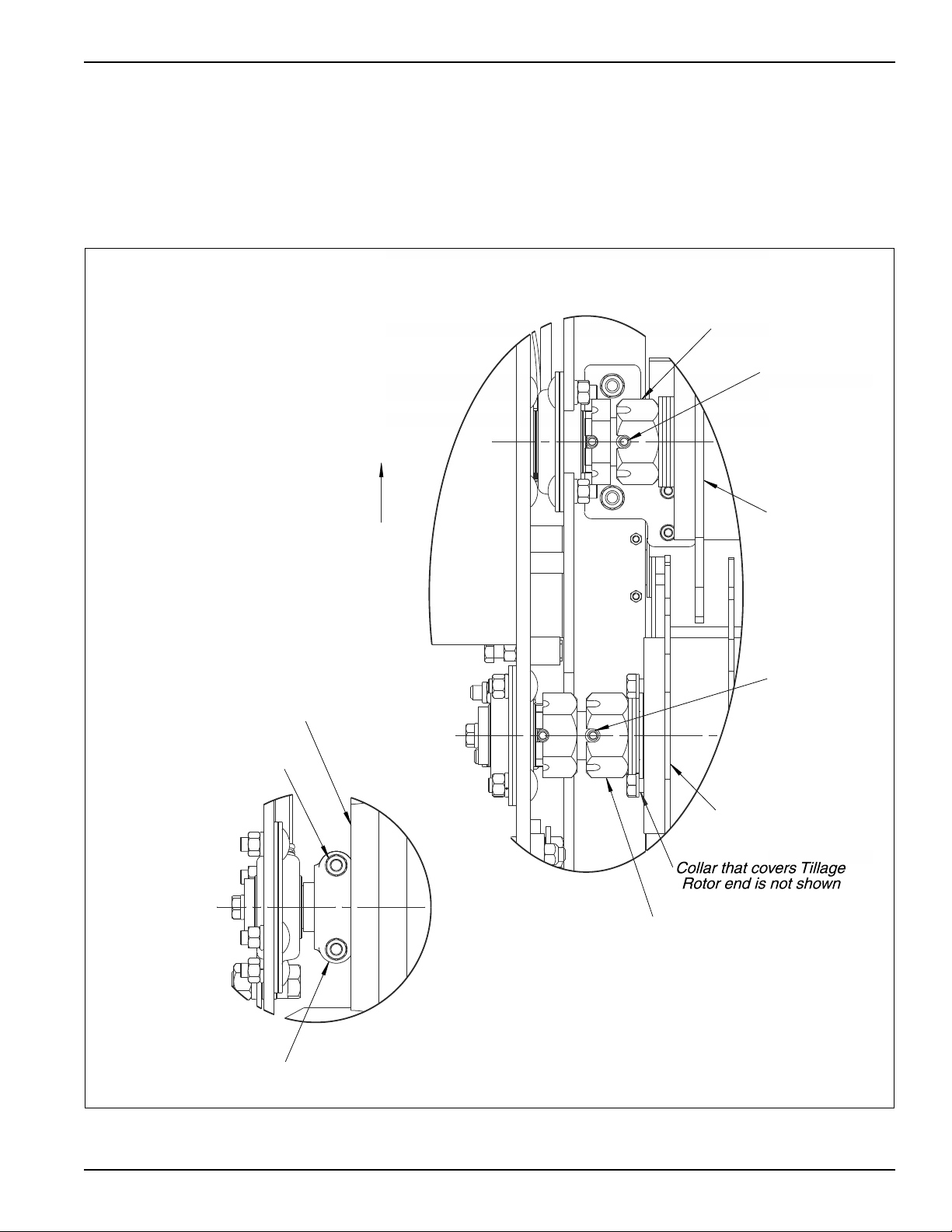
• Check and replace bent or damaged Rotor Blades.
• Regularly check Rotor Blade tightness, if adjustment is
needed remove Roll Pin and torque the Slotted Hex
Nut to 400 Ft-Lbs. Re-insert the Roll Pin.
Right side of the machine is shown.
Firming Roller
• Check the Firming Roller regularly for tightness
between wheels, if adjustment is needed loosen the
Hex Nuts and Slide the clamp over. Re-tighten Hex
Nuts.
Right side of the machine is shown.
Figure 4-7: Rotor Blade and Firming Roller
4-7
Page 50

MAINTENANCE
Maintenance Chart
(Subject to change without notice)
Initial Run - In 8 Hours 25 Hours Annually Storage
Fasteners X X
Grease Rockshaft bearings X X
Grease Rockshaft Link X X
Grease Guide Wheel Hub X X
Grease Rotor and Roller Bearings X X
Lubricate Roller Chains X X X
Adjust Roller Chain tension X X X
Adjust Rotor Thrust Guide X X X
Tighten Rotor Blades and Roller
Wheels
**Clean Machine X
Grease After Cleaning X
Touch-Up Paint X
XXX
** Avoid spraying high pressure water directly at bearing
seals and electrical components.
4-8 3P091
Page 51

Troubleshooting
Problem Solution
MAINTENANCE
Machine is shaking or Tillage Rotor is
bouncing
Machine is shaking and Drive Rotor is
not Turning
Drive Rotor is skidding Check for items that maybe plugging rotors
Tillage Rotor Teeth plugging up with
soil and vegetation
Tillage Rotor plugging with long grass Grass is too wet or green for seeder operation
Uneven seed distribution or uneven
stand
Seed is not coming out Check if Transmission Klik Pin is in place
Engage Gage Wheels with ground
Reduce operating depth of Tillage Rotor
Increase air pressure in Air Shock
Check if rotors are plugged
Check rotor drive chain
Too much air pressure in Air Shock
Rockshaft Lock Pin was left in
Rockshaft Lock Clamp was not loosened
Check rotor drive chain
Soil is too wet for seeder operation
Check for plugged seed cups
Check to see if agitator is working properly
Check if Drive Rotor is loosing traction
If so, reduce pressure in Air Shock
Check if seed is in Seedbox
Nick marks on rotor assembly from
opposite side
Check if Transmission chains are properly adjusted
Large rotor Castle Nuts are not tight enough
Tighten nuts which clamp the blade stack to 400 ft-lbs
4-9
Page 52

MAINTENANCE
able provided for your general use with this manual.
NOTES:
4-10 3P091
Page 53

Chapter 5
Reference Tables and Specifications
Model Designation BPS6 BPSB6
Weight (Empty) 2004 lbs 2111 lbs
Tractor Lift Capacity 2050 lbs (24” behind Lift Arms) 2150 lbs (Behind Lift Arms)
Seed Box Front Box Only Front and Rear Box
Seedbox capacity 4.5 Bushels 4.5 Bushels and 1.4 Bushels
Seed Metering Large Micro-Meter Large and Small Micro-Meter
Common Features
Tractor Horsepower Range 35 to 60 HP
Three Point Hitch Type Category I, II, Quick-Attach, iMatch™
Overall Width 90"
Working Width 72"
Base Unit Length 46"
Unit Height 50"
Recommended Speed 4 to 8 mph (6.4 to 12.9 km/h) (Dependent on Conditions)
Acres per hour 2.9 @ 4 mph, 5.8 @ 8 mph
Rotor Axles 1.75" Square Shaft
Rotor & Roller Bearings 1.5" Heavy Duty Greaseable Bearing
Drive Rotor (Front) 414 lbs
Number of Blades 31
Blade Material Abrasion Resistant Steel
Blade Spacing 2.25"
Blade Thickness 0.313"
Blade Outside Diameter 13”
Drive Type Ground
Tillage Rotor (Middle) 351 lbs
Number of Blades 32
Blade Material Abrasion Resistant Steel
Blade Spacing 2.25"
Blade Thickness 0.188"
Blade Outside Diameter 13"
Drive Ratio 2:01
Rotor Speed 197 RPM @ 4 MPH, 394 RPM @ 8 MPH
Drive Type #80 Roller Chain
Firming Roller (Rear) 231 lbs
Number of Cast Wheels 37
Seed Metering Drive Positive Ground Driven
Seedbox Drive Type #40 Roller Chain
5-1
Page 54

REFERENCE TABLES AND SPECIFICATIONS
Table provided for your general use with this manual.
NOTES:
5-2 3P091
Page 55

Document Control Revision Log:
Date Revision Improvement(s) Description and Comments
03/2011 311rev0511 Initial Release
09/2011 311rev0911 Updated, Incorporated Landoll Format
03/2013 311rev0313 Added New Acre Meter Data
Page 56

Equipment from Landoll Corporation is built to exacting
standards ensured by ISO 9001:2008 registration at all
Landoll manufacturing facilities.
Till ‘N Seed®
Models BPS6 and BPSB6
Operator’s Manual
Re-Order Part Number 3P091
LANDOLL CORPORATION
1900 North Street
Marysville, Kansas 66508
(785) 562-5381
800-428-5655 ~ WWW.LANDOLL.COM
Copyright 2013. Landoll Corporation
"All rights reserved, including the right to reproduce this material or portions thereof in any form”.
311rev0313 3P091
 Loading...