


5531
Table of contents
 Loading...
Model 5531
Grain Drill
Operator’ s Manual
LANDOLL CORPORATION
1900 North Street
Marysville, Kansas 66508
(785) 562-5381
800-428-5655 ~ WWW.LANDOLL.COM
F-716-1213 12/2013

1-2 f-716-1213 Edition

1 Introduction
Understanding Safety Statements . . . . . . . . . . . . . . . . . . . . . . . . . . . . . . . . . . . . . . . . . . . . . . . . 1-2
2 Standard Specifications
3 Assembly Instructions
Press Wheel Assembly . . . . . . . . . . . . . . . . . . . . . . . . . . . . . . . . . . . . . . . . . . . . . . . . . . . . . . . . . 3-2
Small Seed Attachment Installation (Option) . . . . . . . . . . . . . . . . . . . . . . . . . . . . . . . . . . . . . . . 3-4
4 Operation and Maintenance
Tractor Preparation . . . . . . . . . . . . . . . . . . . . . . . . . . . . . . . . . . . . . . . . . . . . . . . . . . . . . . . . . . . . 4-2
Grain Drill Preparation . . . . . . . . . . . . . . . . . . . . . . . . . . . . . . . . . . . . . . . . . . . . . . . . . . . . . . . . . . 4-2
Table of Contents
Attaching Grain Drill To The Tractor . . . . . . . . . . . . . . . . . . . . . . . . . . . . . . . . . . . . . . . . . . . . . . 4-3
Transport Locks . . . . . . . . . . . . . . . . . . . . . . . . . . . . . . . . . . . . . . . . . . . . . . . . . . . . . . . . . . . . . . . 4-4
Folding/Unfolding the Grain Drill . . . . . . . . . . . . . . . . . . . . . . . . . . . . . . . . . . . . . . . . . . . . . . . . . 4-5
Leveling the Hitch Clevis . . . . . . . . . . . . . . . . . . . . . . . . . . . . . . . . . . . . . . . . . . . . . . . . . . . . . . . . 4-6
Leveling the Hitch . . . . . . . . . . . . . . . . . . . . . . . . . . . . . . . . . . . . . . . . . . . . . . . . . . . . . . . . . . . . . 4-7
Transporting the Grain Drill . . . . . . . . . . . . . . . . . . . . . . . . . . . . . . . . . . . . . . . . . . . . . . . . . . . . . 4-8
Compressor Operation . . . . . . . . . . . . . . . . . . . . . . . . . . . . . . . . . . . . . . . . . . . . . . . . . . . . . . . . 4-10
Air System Pressure . . . . . . . . . . . . . . . . . . . . . . . . . . . . . . . . . . . . . . . . . . . . . . . . . . . . . . . . . . 4-11
Openers – Hydraulic Operation . . . . . . . . . . . . . . . . . . . . . . . . . . . . . . . . . . . . . . . . . . . . . . . . . 4-12
Hydraulic Lift System . . . . . . . . . . . . . . . . . . . . . . . . . . . . . . . . . . . . . . . . . . . . . . . . . . . . . . . . . 4-13
Loup II Drill Monitor Operation . . . . . . . . . . . . . . . . . . . . . . . . . . . . . . . . . . . . . . . . . . . . . . . . . . 4-14
Seed Meter Gate Adjustment . . . . . . . . . . . . . . . . . . . . . . . . . . . . . . . . . . . . . . . . . . . . . . . . . . . 4-15
Seed Rate Adjustment . . . . . . . . . . . . . . . . . . . . . . . . . . . . . . . . . . . . . . . . . . . . . . . . . . . . . . . . . 4-16
Meter/Seed Rate Handle Adjustment . . . . . . . . . . . . . . . . . . . . . . . . . . . . . . . . . . . . . . . . . . . . . 4-17
Seed Rate Calibration . . . . . . . . . . . . . . . . . . . . . . . . . . . . . . . . . . . . . . . . . . . . . . . . . . . . . . . . . 4-19
Dry Fertilizer Combination Box . . . . . . . . . . . . . . . . . . . . . . . . . . . . . . . . . . . . . . . . . . . . . . . . . 4-20
Fertilizer Box – Clean Out . . . . . . . . . . . . . . . . . . . . . . . . . . . . . . . . . . . . . . . . . . . . . . . . . . . . . . 4-22
Fertilizer – Rate Adjustment . . . . . . . . . . . . . . . . . . . . . . . . . . . . . . . . . . . . . . . . . . . . . . . . . . . . 4-23
Fertilizer – Rate Calibration . . . . . . . . . . . . . . . . . . . . . . . . . . . . . . . . . . . . . . . . . . . . . . . . . . . . . 4-24
Small Seed Rate Adjustment . . . . . . . . . . . . . . . . . . . . . . . . . . . . . . . . . . . . . . . . . . . . . . . . . . . 4-25
F-716-1213 Edition i

Small Seed Meter Assembly/Adjustment . . . . . . . . . . . . . . . . . . . . . . . . . . . . . . . . . . . . . . . . . . 4-26
Air Spring Adjustment . . . . . . . . . . . . . . . . . . . . . . . . . . . . . . . . . . . . . . . . . . . . . . . . . . . . . . . . . 4-27
Opener Blade Adjustment . . . . . . . . . . . . . . . . . . . . . . . . . . . . . . . . . . . . . . . . . . . . . . . . . . . . . . 4-28
Opener – Press Wheel Adjustment . . . . . . . . . . . . . . . . . . . . . . . . . . . . . . . . . . . . . . . . . . . . . . . 4-29
Opener Scraper Adjustment . . . . . . . . . . . . . . . . . . . . . . . . . . . . . . . . . . . . . . . . . . . . . . . . . . . . 4-30
Opener Soil Strip Adjustment . . . . . . . . . . . . . . . . . . . . . . . . . . . . . . . . . . . . . . . . . . . . . . . . . . . 4-31
Drive Shaft – Coupler Alignment . . . . . . . . . . . . . . . . . . . . . . . . . . . . . . . . . . . . . . . . . . . . . . . . 4-32
Walkboard . . . . . . . . . . . . . . . . . . . . . . . . . . . . . . . . . . . . . . . . . . . . . . . . . . . . . . . . . . . . . . . . . . . 4-33
Ladder Use and Transport Requirements . . . . . . . . . . . . . . . . . . . . . . . . . . . . . . . . . . . . . . . . . 4-34
Hydraulic Row Markers (Option) . . . . . . . . . . . . . . . . . . . . . . . . . . . . . . . . . . . . . . . . . . . . . . . . . 4-35
Hydraulic Row Marker Disc Adjustment (Option) . . . . . . . . . . . . . . . . . . . . . . . . . . . . . . . . . . . 4-36
5531 Point Row Clutch (Option) . . . . . . . . . . . . . . . . . . . . . . . . . . . . . . . . . . . . . . . . . . . . . . . . . 4-37
Wheel Bearing Maintenance . . . . . . . . . . . . . . . . . . . . . . . . . . . . . . . . . . . . . . . . . . . . . . . . . . . . 4-38
Hydraulic Maintenance . . . . . . . . . . . . . . . . . . . . . . . . . . . . . . . . . . . . . . . . . . . . . . . . . . . . . . . . 4-38
Hose Identification . . . . . . . . . . . . . . . . . . . . . . . . . . . . . . . . . . . . . . . . . . . . . . . . . . . . . . . . . . . . 4-39
Parking . . . . . . . . . . . . . . . . . . . . . . . . . . . . . . . . . . . . . . . . . . . . . . . . . . . . . . . . . . . . . . . . . . . . . 4-40
Lubrication Maintenance . . . . . . . . . . . . . . . . . . . . . . . . . . . . . . . . . . . . . . . . . . . . . . . . . . . . . . . 4-42
Storage . . . . . . . . . . . . . . . . . . . . . . . . . . . . . . . . . . . . . . . . . . . . . . . . . . . . . . . . . . . . . . . . . . . . . 4-42
5 Troubleshooting Guide
ii F-716-1213 Edition

Chapter 1
Introduction
The Landoll Model 5531 Grain Drill is a quality product designed to give years of trouble free performance. By
following each section of this manual, your system will perform as designed for you and your operation
CHAPTER 1 gives basic instructions on the use of this manual.
CHAPTER 2 gives product specifications. These specifications supply lengths and measures for your
equipment. A S tandard Bolt Torque Table is provided to give guidelines for bolt to rques to
be used when servicing this product.
CHAPTER 3 contains assembly instructions for your Model 5531 Grain Drill. When these procedures
are correctly followed, your equipment should provide you years of trouble-free operation
and service.
CHAPTER 4 instructs how to operate your equipment before using it, and describes adjustments
needed. It also gives practical advice for the care and maintenance of your Landoll
equipment. Drawings in this section locate adjustment points on the equipment.
NOTE: IF THE EQUIPMENT IS IMPROPERLY ASSEMBLED OR MAINTAINED, THE
WARRANTY IS VOID. IF YOU HAVE ANY QUESTIONS CONTACT:
LANDOLL CORPORATION
1900 NORTH STREET
MARYSVILLE, KANSAS 66508
or phone:
(785) 562-5381 or
(800) 428-5655
or FAX:
(888) 527-3909
CHAPTER 5 is a troubleshooting guide to aid in diagnosing and solving problems with the equipment.
PARTS LIST is a separate manual showing the various assemblies, subassemblies, and systems.
Refer to that manual when ordering Landoll replacement parts. Order parts from your
Landoll dealer.
WARRANTY The Warranty Registration form is included with the product documents. Fill it out and
mail it within 15 days of purchase
NOTE: IMPROPER ASSEMBLY, MODIFICATION, OR MAINTENANCE OF YOUR
LANDOLL MACHINE CAN VOID YOUR WARRANTY.
COMMENTS Address comments or questions regarding this publication to:
LANDOLL CORPORATION
1900 NORTH STREET
MARYSVILLE, KANSAS 66508
ATTENTION: PUBLICATIONS -DEPT. 55
1-1

INTRODUCTION
DANGER
WARNING
CAUTION
NOTE
NOTE
Understanding Safety Statements
You will find various types of safety information on the
following pages and on the machine signs (decals)
attached to the vehicle. This section explains their
meaning.
The Safety Alert Symbol means ATTENTION! YOUR
SAFETY IS INVOLVED!
Danger means a life-threatenin g sit ua ti on ex is ts.
Death can occur if safety measures or
instructions on this label are not properly
followed.
Warning means serious injury or death can occur
if safety measures or instructions on this label
are not properly followed.
Caution means serious equipment or other
property damage can occur if instruction s on this
label are not properly followed.
Means that failure to follow these instructions could
cause damage to the equipment or cause it to operate
improperly.
Make sure you read and understand the informatio n
contained in this manual and on the machine signs
(decals) before you attempt to operate or maintain this
vehicle.
The safety statements contai ned in this manual relate to
the operation of the Model 5531 Grain Drill.
1-2 F-716-1213 Edition

Standard Specifications
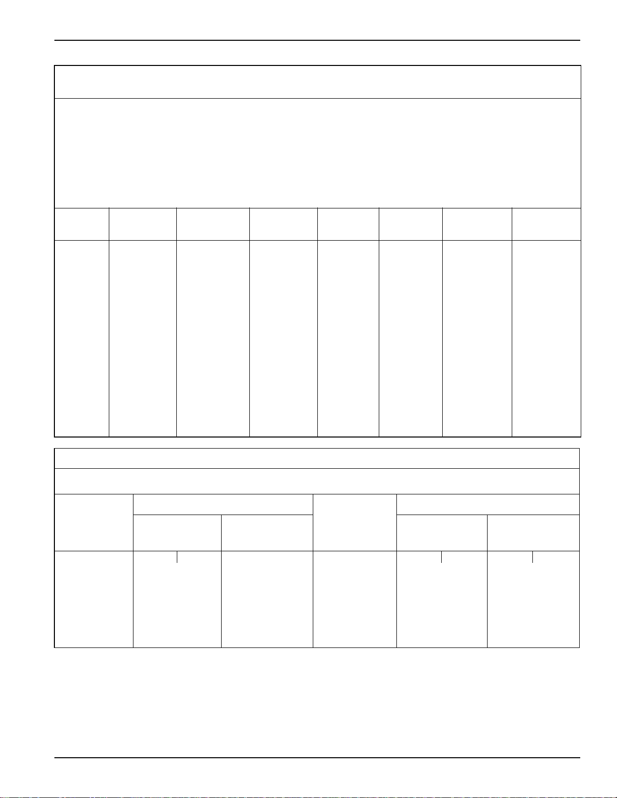
5531 SERIES GRAIN DRILL
Chapter 2
MODEL
NUMBER
5531-30X7.5
5531-30X10
5531-40X7.5
5531-40X10
Specifications are subject to change withou t prior notification.
MODEL
NUMBER
5531-30X7.5
5531-30X10
5531-40X7.5
5531-40X10
Specifications are subject to change withou t prior notification.
WORKING
WIDTH
30’-0” 7-1/2” 48 14’-6” (4) 380/55R 16.5
30’-0” 10” 36 14’-6” 17,010
40’-0” 7-1/2” 64 14’-6” 24,560
40’-0” 10” 48 14’-6” 22,640
WORKING
WIDTH
30’-0” 7-1/2” 48 14’-6” (4) 380/55R 16.5
30’-0” 10” 36 14’-6” 17,500
40’-0” 7-1/2” 64 14’-6” 24,560
40’-0” 10” 48 14’-6” 22,560
ROW
SPACING
5531 SERIES GRAIN DRILL W/ FERTILIZER
ROW
SPACING
NO. OF
OPENERS
NO. OF
OPENERS
TRANSPORT
TRANSPORT
WIDTH
WIDTH
TIRE AND
WHEELS
(frame)
(4) 11L -15,
12 ply - 6 bolt (wing)
TIRE AND
WHEELS
(frame)
(4) 11L -15,
12 ply - 6 bolt (wing)
ESTIMATED
WEIGHT (LBS.)
18,450
ESTIMATED
WEIGHT (LBS.)
18,990
5531 SERIES GRAIN DRILL W/ SMALL GRASS SEED
MODEL
NUMBER
5531-30X7.5
5531-40X7.5
Specifications are subject to change withou t prior notification.
WORKING
WIDTH
30’-0” 7-1/2” 48 15 ’-6 ” (4) 380/55R 16.5
40’-0” 7-1/2” 64 15’-6” 24,560
ROW
SPACING
NO. OF
OPENERS
TRANSPORT
WIDTH
TIRE AND
WHEELS
(frame)
(4) 11L -15,
12 ply - 6 bolt (wing)
ESTIMATED
WEIGHT (LBS.)
18,990
2-1

STANDARD SPECIFICATIONS
TIRE INFLATION
TIRE
SIZE
380/55R 16.5 Goodyear 150A8/B 7400 lbs. @30
380/60R 16.5 Goodyear 150A8/B 7400 lbs. @30
11L x 15 Goodyear 12 Ply/3860 lbs 52 psi
MANUFACTURER
TIRE
mph
mph
PLY/LOAD
RATING
INFLATION PRESSURE
74 psi
73 psi
(psi) (max.)
2-2 F-716-1213 Edition
STANDARD SPECIFICATIONS
LANDOLL CORPORATION
GENERAL TORQUE SPECIFICATIONS (REV. 4/97)
THIS CHART PROVIDES TIGHTENING TORQUES FOR GENERAL PURPOSE APPLICATIONS WHEN SPECIAL TORQUES ARE NOT SPECIFIED ON PROCESS
OR DRAWING.
ASSEMBLY TORQUES APPLY TO PLATED NUTS AND CAPSCREWS ASSEMBLED WITHOUT SUPPLEMENTAL LUBRICATIO N (AS RECEIVED CONDITION).
THEY DO NOT APPLY IF SPECIAL GRAPHITE MOLY-DISULFIDE OR OTHER EXTREME PRESSURE LUBRICANTS ARE USED.
WHEN FASTENERS ARE DRY (SOLVENT CLEANED), ADD 33% TO AS RECEIVED CONDITION TORQUE.
BOLT HEAD IDENTIFICATION MARKS INDICATE GRADE AND MAY VAR Y FROM MANUFACTURER TO MANUFACTURER.
THICK NUTS MUST BE USED ON GRADE 8 CAPSCREWS.
USE VALUE IN [ ] IF USING PREVAILING TORQUE NUTS.
TORQUE IS SPECIFIED IN FOOT POUNDS
UNC
Size
SAE Grade2SAE Grade5SAE Grade
8
UNF
Size
SAE Grade 2SAE Grade5SAE Grade
8
1/4-20 4 [5] 6 [7] 9 [11] 1/4-28 5 [6] 7 [9] 10 [12]
5/16-18 8 [10] 13 [16] 18 [22] 5/16-24 9 [11] 14 [17] 20 [25]
3/8-16 15 [19] 23 [29] 35 [43] 3/8-24 17 [21] 25 [31] 35 [44]
7/16-14 24 [30] 35 [43] 55 [62] 7/16-20 27 [34] 40 [50] 60 [75]
1/2-13 35 [43] 55 [62] 80 [100] 1/2-20 40 [50] 65 [81] 90 [112]
9/16-12 55 [62] 80 [100] 1 1 0 [137] 9/16-18 60 [75] 90 [112] 130 [162]
5/8-11 75 [94] 110 [137] 170 [212] 5/8-18 85 [106] 130 [162] 180 [225]
3/4-10 130 [162] 200 [250] 280 [350] 3/4-16 150 [188] 220 [275] 320 [400]
7/8-9 125 [156] 320 [400] 460 [575] 7/8-14 140 [175] 360 [450] 500 [625]
1-8 190 [237] 408 [506] 680 [850] 1-14 210 [263] 540 [675] 760 [950]
1-1/8-7 270 [337] 600 [750] 960 [1200] 1-1/8-12 300 [375] 660 [825] 1080 [1350]
1-1/4-7 380 [475] 840 [1050] 1426 [1782] 1-1/4-12 420 [525] 920 [1150] 1500 [1875]
1-3/8-6 490 [612] 110 [1375] 1780 [2225] 1-3/8-12 560 [700] 1260 [1575] 2010 [2512]
1-1/2-6 650 [812] 1460 [1825] 2360 [2950] 1-1/2-12 730 [912] 1640 [2050] 2660 [3325]
1-3/4-5 736 [920] 1651 [2063] 2678 [3347] 1-3/4-12 920 [1150] 2063 [2579] 3347 [4183]
METRIC
COARSE THREAD METRIC CLASS 10.9 FASTENERS AND CLASS 10.0 NUTS AND THROUGH HARDENED FLAT WASHERS, PHOSPHATE COATED, ROCKWELL
“C” 38-45.
USE VALUE IN [ ] IF USING PREVAILING TORQUE NUTS.
Nominal
Thread
Diameter
mm
Standard Torque Nominal
Newton-
Meters
Foot-
Pounds
Thread
Diameter
mm
Standard Torque
Newton-
Meters
Foot-
Pounds
6 10 [14] 7 [10] 20 385 [450] 290 [335]
7 16 [22] 12 [16] 24 670 [775] 500 [625]
8 23 [32] 17 [24] 27 980 [1105] 730 [825]
10 46 [60] 34 [47] 30 1330 [1470] 990 [1090]
12 80 [101] 60 [75] 33 1790 [1950] 1340 [1450]
14 125 [155] 90 [115] 36 2325 [2515] 1730 [1870]
16 200 [240] 150 [180] 39 3010 [3210] 2240 [2380]
18 275 [330] 205 [245]
Table 2-1: General Torque Specifications
2-3

STANDARD SPECIFICATIONS
LANDOLL CORPORATION
HYDRAULIC FITTING TORQUE SPECIFICATIONS
THIS CHART PROVIDES TIGHTENING TORQUES FOR HYDRAULIC FITTING APPLICATIONS WHEN SPECIAL TORQUES ARE NOT SPECIFIED ON PROCESS
OR DRAWING.
ASSEMBLY TORQUES APPLY TO PLATED CARBON STEEL AND STAINLESS STEEL FITTINGS ASSEMBLED WITHOUT SUPPLEMENTAL LUBRICATION (AS
RECEIVED CONDITION). THEY DO NOT APPLY IF SPECIAL GRAPHITE MOLY-DISULFIDE OR OTHER EXTREME PRESSURE LUBRICANTS ARE USED.
BRASS FITTINGS AND ADAPTERS - 65% OF THE TORQUE VALUE FOR STEEL. STAINLESS STEEL, ALUMINUM AND MONEL - THREADS ARE TO BE
LUBRICATED
.
TORQUE IS SPECIFIED IN FOOT POUNDS
Dash Size 37 Degree JIC O-Ring (ORS) O-Ring Boss (ORB)
-4 11-13 15-17 13-15
-5 14-16 — 21-23
-6 20-22 34-36 25-29
-8 43-47 58-62 40-44
-10 55-65 100-110 57.5-62.5
-12 80-90 134-146 75-85
-16 115-125 202-218 109-121
-20 160-180 248-272 213-237
-24 185-215 303-327 238-262
-32 250-290 — 310-340
o
37
JIC, ORS, & ORB (REV. 10/97)
PARKER BRAND FITTINGS
GATES BRAND FITTINGS
Dash Size 37 Degree JIC O-Ring (ORS) O-Ring Boss (ORB)
-4 10-11 10-12 14-16
-5 13-15 — —
-6 17-19 18-20 24-26
-8 34-38 32-40 37-44
-10 50-56 46-56 50-60
-12 70-78 65-80 75-83
-14 — 65-80 —
-16 94-104 92-105 111-125
-20 124-138 125-140 133-152
-24 156-173 150-180 156-184
-32 219-243 — —
AEROQUIP BRAND FITTINGS
Dash Size 37 Degree JIC O-Ring (ORS) O-Ring Boss (ORB)
-4 11-12 10-12 14-16
-5 15-16 — 18-20
-6 18-20 18-20 24-26
-8 38-42 32-35 50-60
-10 57-62 46-50 72-80
-12 79-87 65-70 125-135
-14 — — 160-180
-16 108-113 92-100 200-220
-20 127-133 125-140 210-280
-24 158-167 150-165 270-360
-32 245-258 — —
Table 2-2: Hydraulic Fitting Torque Specifications
2-4 F-716-1213 Edition
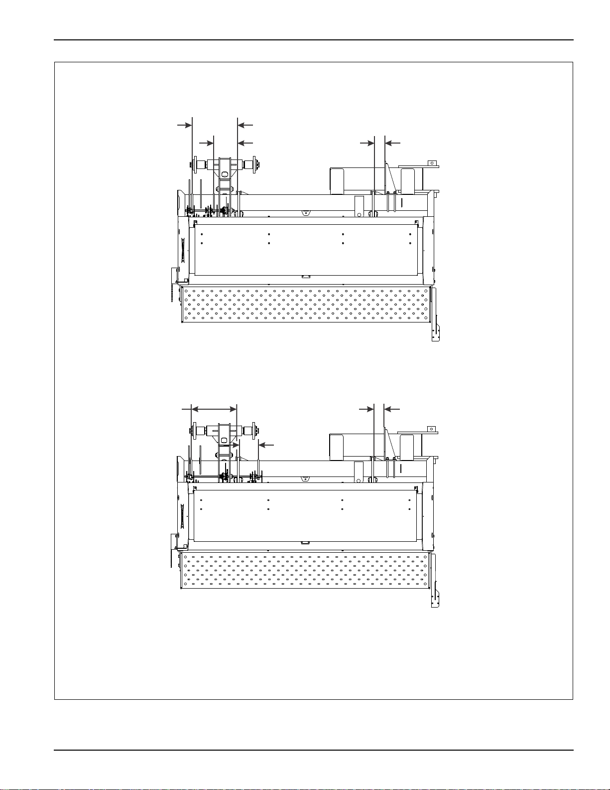
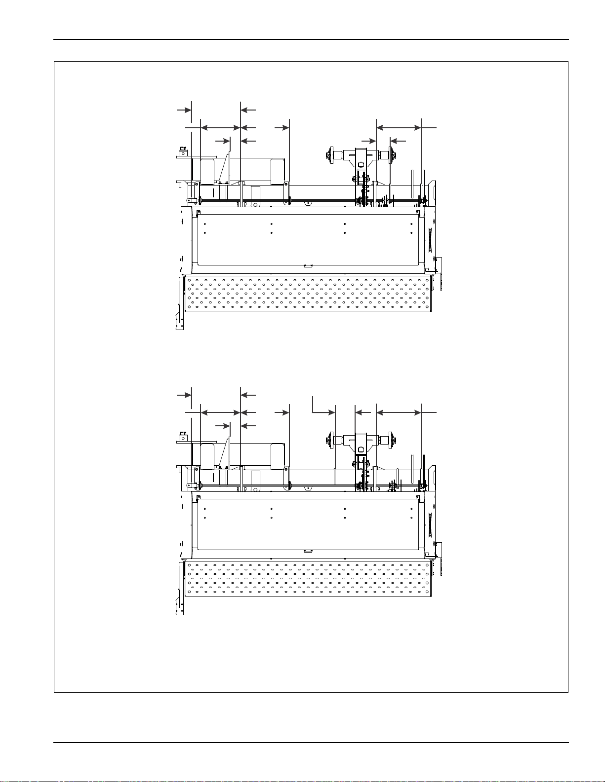
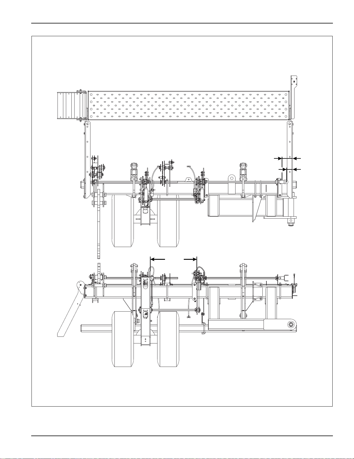
5531-30’
SEED BOX
7-1/2” SPACING
LEFT WING
5531-30’
LEFT WING SEED BOX
10” SPACING
20-3/8
10-5/8
4-5/8
20-3/8
26-1/8
4-5/8
5531-30 left wing
STANDARD SPECIFICATIONS
Figure 2-1: 5531-30 Left Wing Placement
2-5
STANDARD SPECIFICATIONS
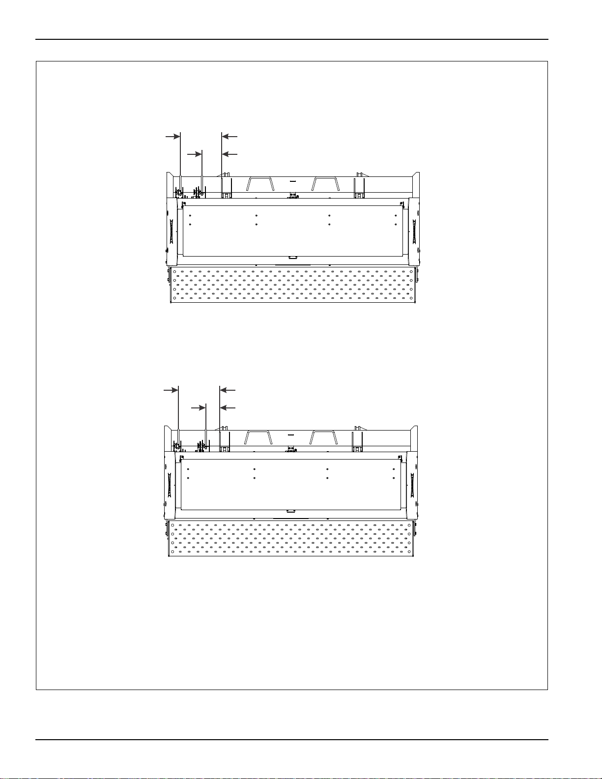
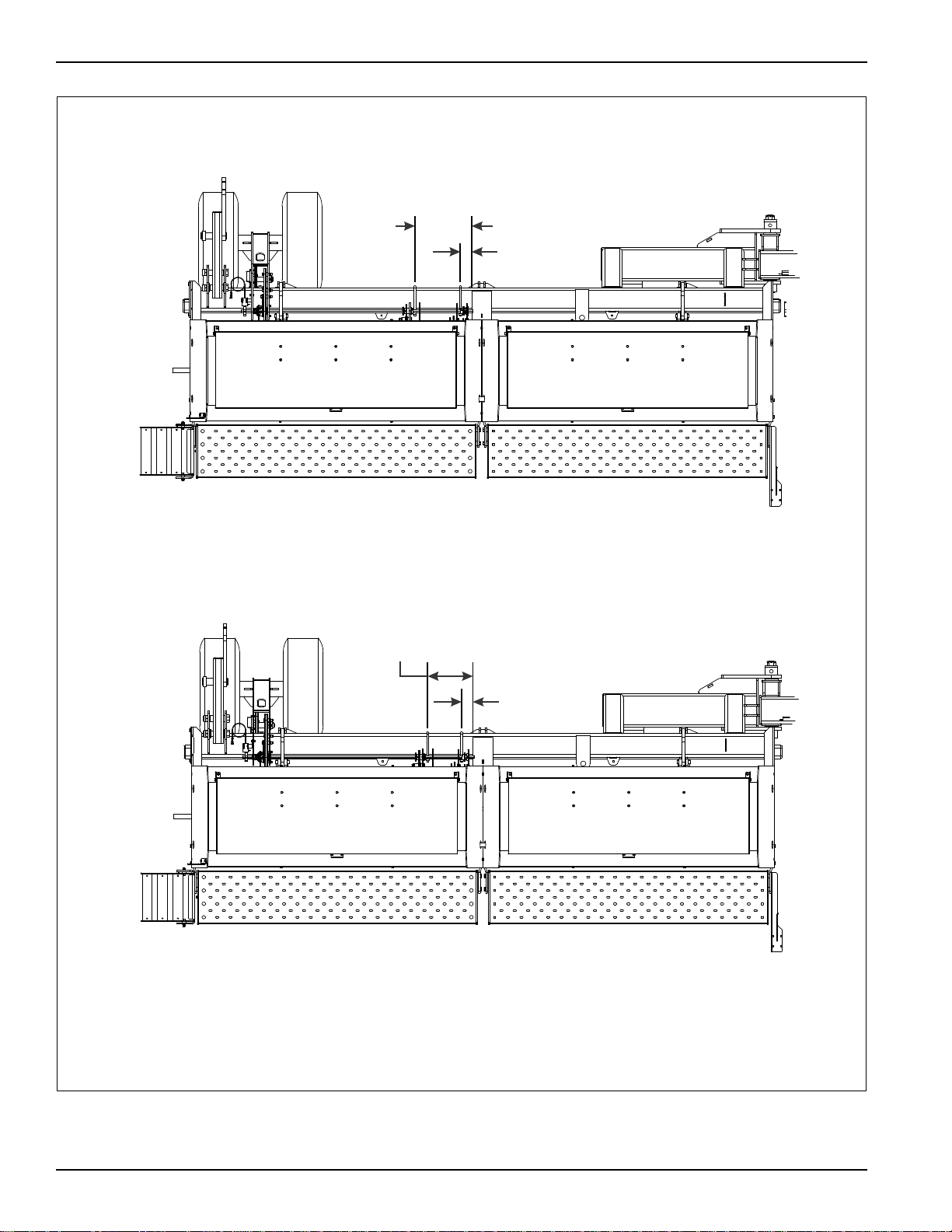
18-1/2
8-5/8
5531-30’
CENTER SEED BOX
7-1/2” SPACING
5531-30’
CENTER SEED BOX
10” SPACING
18-1/2
5-1/16
5531-30 center
Figure 2-2: 5531-30 Center Placement
2-6 F-716-1213 Edition
STANDARD SPECIFICATIONS
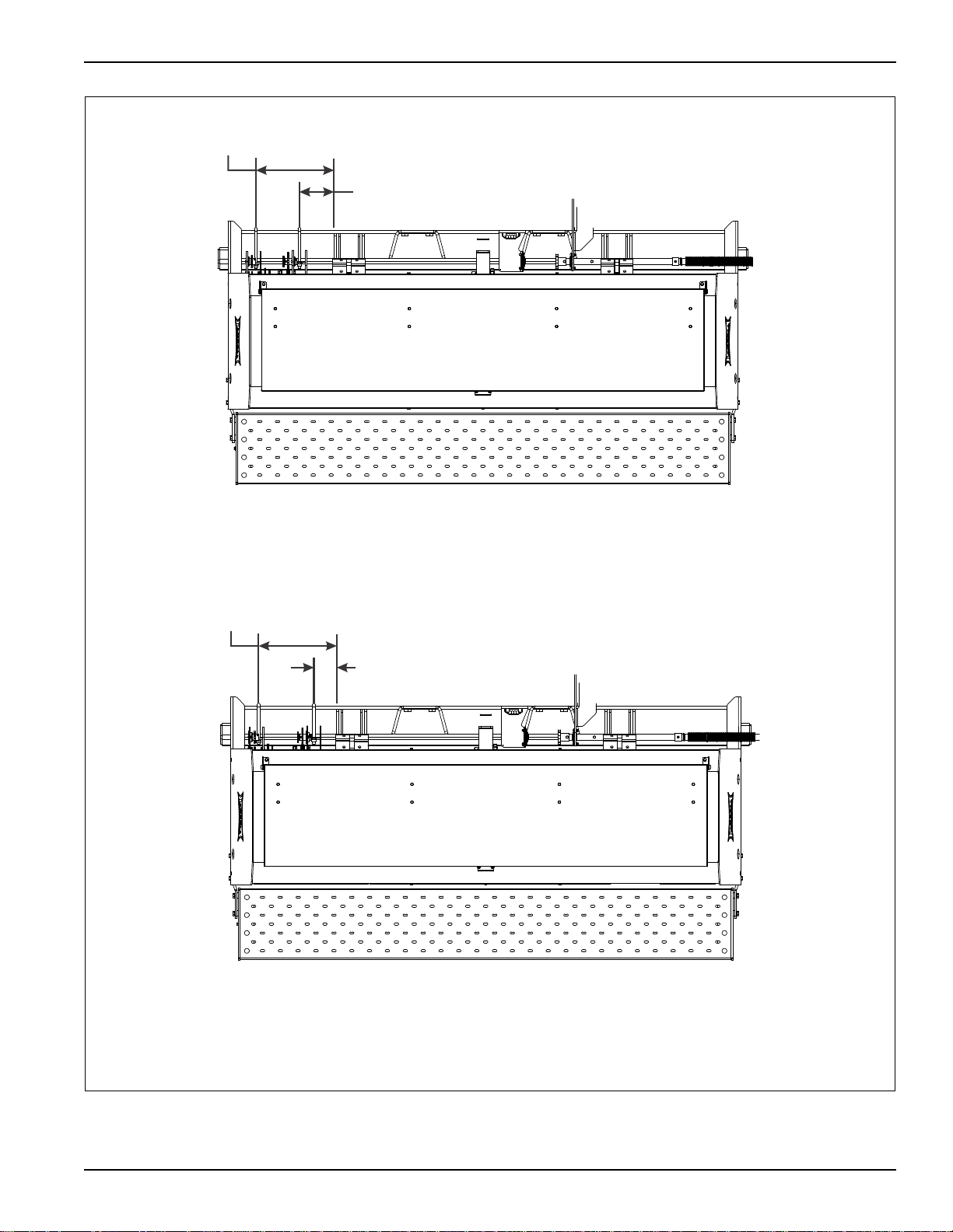
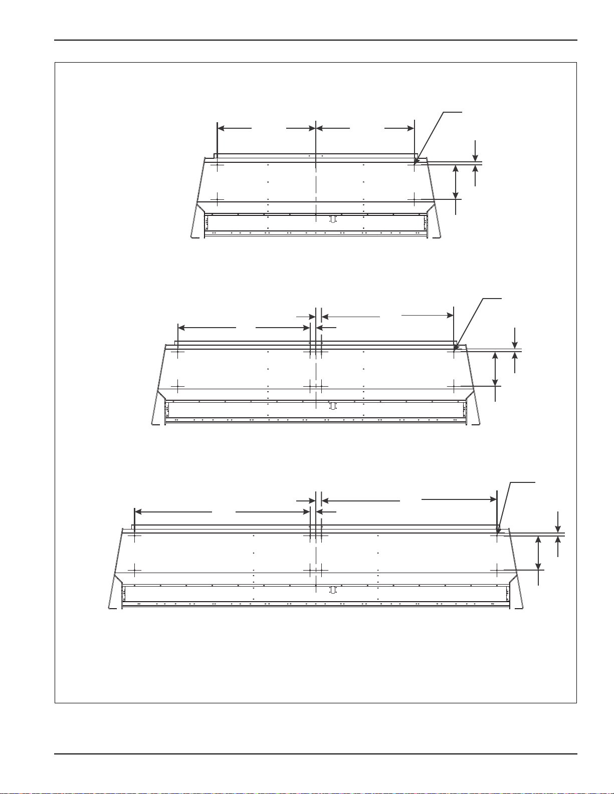
5531-30’
SEED BOX
7-1/2” SPACING
RIGHT WING
5531-30’
RIGHT WING SEED BOX
10” SPACING
21-15/16
4-5/8
10-9/16
18-1/4 22 20-3/8
21-15/16
4-5/8
17-3/4
18-1/4
22
20-3/8
5531-30 right wing
Figure 2-3: 5531-30 Right Wing Placement
2-7
STANDARD SPECIFICATIONS
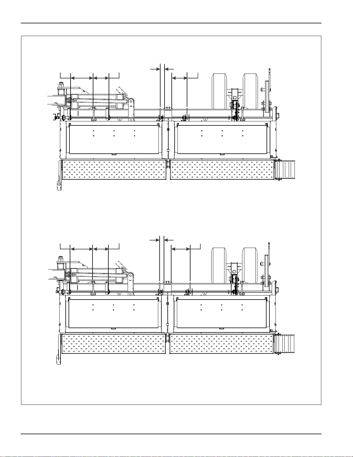
18-1/4
LEFT OUTER
WING SEED BOX
LEFT INNER
WING SEED BOX
5531-40
LEFT WING SEED BOXES
7-1/2” SPACING
21
LEFT OUTER
WING BOXSEED
LEFT INNER
WING BOXSEED
5531-40
LEFT WING SEED BOXES
10” SPACING
5531-40 left wing placement
3-3/8
3-3/8
2-8 F-716-1213 Edition
Figure 2-4: 5531-40 Left Wing Placement
18-1/2
5531-40
CENTER SEED BOX
7-1/2” SPACING
5531-40 center placement
8-5/8
5531-40
CENTER SEED BOX
10” SPACING
18-1/2
5-1/16
STANDARD SPECIFICATIONS
Figure 2-5: 5531-40 Center Placement
2-9
STANDARD SPECIFICATIONS
18-1/4
12-3/4
3-3/8
13-1/4
RIGHT INNER
WING BOXSEED
RIGHT OUTER
WING BOXSEED
5531-40
RIGHT WING BOXES
7-1/2” SPACING
SEED
18-1/4 12-3/4 3-3/8 16
RIGHT INNER
WING BOXSEED
RIGHT OUTER
WING BOXSEED
5531-40
RIGHT WING BOXES
10” SPACING
SEED
5531-40 right wing placement
2-10 F-716-1213 Edition
Figure 2-6: 5531-40 Right Wing Placement
STANDARD SPECIFICATIONS
5-29/32
3-13/32
25-5/8
5531-30 point row clutch placement
Figure 2-7: 5531-30 Point Row Clutch Placement
2-11

STANDARD SPECIFICATIONS
5-29/32
3-13/32
68-13/16
20-7/16
5531-40 point row clutch placement
2-12 F-716-1213 Edition
Figure 2-8: 5531-40 Point Row Clutch Placement
STANDARD SPECIFICATIONS
1
12
34-1/434-1/4
small seed attachment drilling placement
11246
46
2
2
Ø .406
Ø .406
11261
61
2
2
Ø .406
7-1/2’ SEED BOX (P/N 154842)
10’ SEED BOX (P/N 143932)
12-1/2’ SEED BOX (P/N 159102)
Figure 2-9: Small Seed Attachment Drilling Placement
2-13

STANDARD SPECIFICATIONS
Page Intentionally Blank
2-14 F-716-1213 Edition
Your new 5531 Grain Drill comes nearly completely
DANGER
WARNING
DANGER
CAUTION
assembled from the factory and ready to go to the field.
This section includes press wheel and option assembly
procedures.
To insure alignment of assemblies, leave the nuts loose
until completion of final assembly. Use lock washers or
flat washers as specified. Spread all cotter pins.
After completion of final assemb ly, tighten all nuts
evenly to prevent misalignment, distortion or binding.
Tighten all screws and nuts to the recommended torques
(See Table 2-1 on page 2-3.)
Opener blades are extremely sharp. Exercise
extreme care when working on or near opener
blades. Do not allow opener blades to roll over or
fall onto any body part. Do not allow wrenches to
slip when working near blades. Never push
wrenches toward opener blades. Do not climb
over machine above opener blades. Failure to
stay clear of opener blade edges can cause
serious personal injury or death.
Chapter 3
Assembly Instructions
Do not attempt to lift heavy parts (such as the
frame, wheel lift, and pull hitch) manually. Use a
hoist or a forklift to move these parts into
position.
To prevent accidental lowering:
• All hydraulically elevated equipment must be
locked out using the cylinder lockouts.
• Lower equipment to the ground while
servicing or when it is idle.
• Failure to take measures to prevent
accidental lowering may result in serious
personal injury or death.
Be sure to bleed the hydraulic system of all air in
lines after inst allation. Failure to bleed the system
of all air can result in improper machine
operation.
3-1
ASSEMBLY INSTRUCTIONS
DANGER
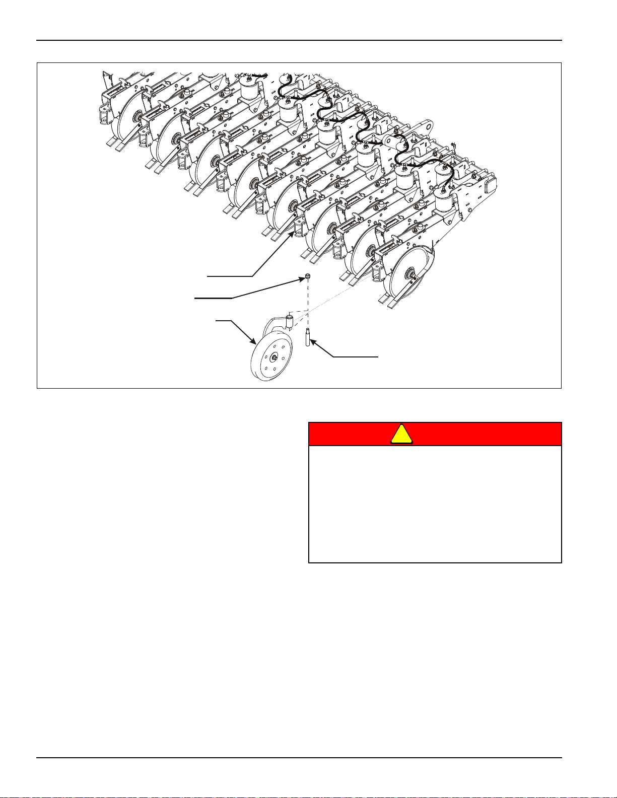
press wheel assembly
AIR OPENER ASSEMBLY
3/4-10 HEX LOCK NUT
PRESS WHEEL ASSEMBLY
PRESS WHEEL ARM
PIN
Figure 3-1: Press Wheel Assembly
Press Wheel Assembly
1. Attach each press wheel assembly to each air
opener assembly on the Grain Drill using press
wheel arm pin and 3/4-10 hex lock nut (See
Figure 3-1.)
Opener blades are extremely sharp. Exercise
extreme care when working on or near opener
blades. Do not allow opener blades to roll o ver or
fall onto any body part. Do not allow wrenche s to
slip when working near blades. Never push
wrenches toward opener blades. Do not climb
over machine above opener blades. Failure to
stay clear of opener blade edges can cause
serious personal injury or death.
3-2 F-716-1213 Edition

5531 small seed attach
EXISTING MAIN SEED
BOX ASSEMBL Y
EXISTING SMV SIGN
SMALL SEED BOX ASSEMBLY
RELOCATED SMV
SIGN
SMALL SEED
SHIELD
BEARING ASSEMBLY
CHAIN ADJUSTMENT
BRACKET
BEARING ASSEMBLY
AND MOUNT
ASSEMBLY INSTRUCTIONS
Figure 3-2: Small Seed Assembly Overview
3-3
ASSEMBLY INSTRUCTIONS
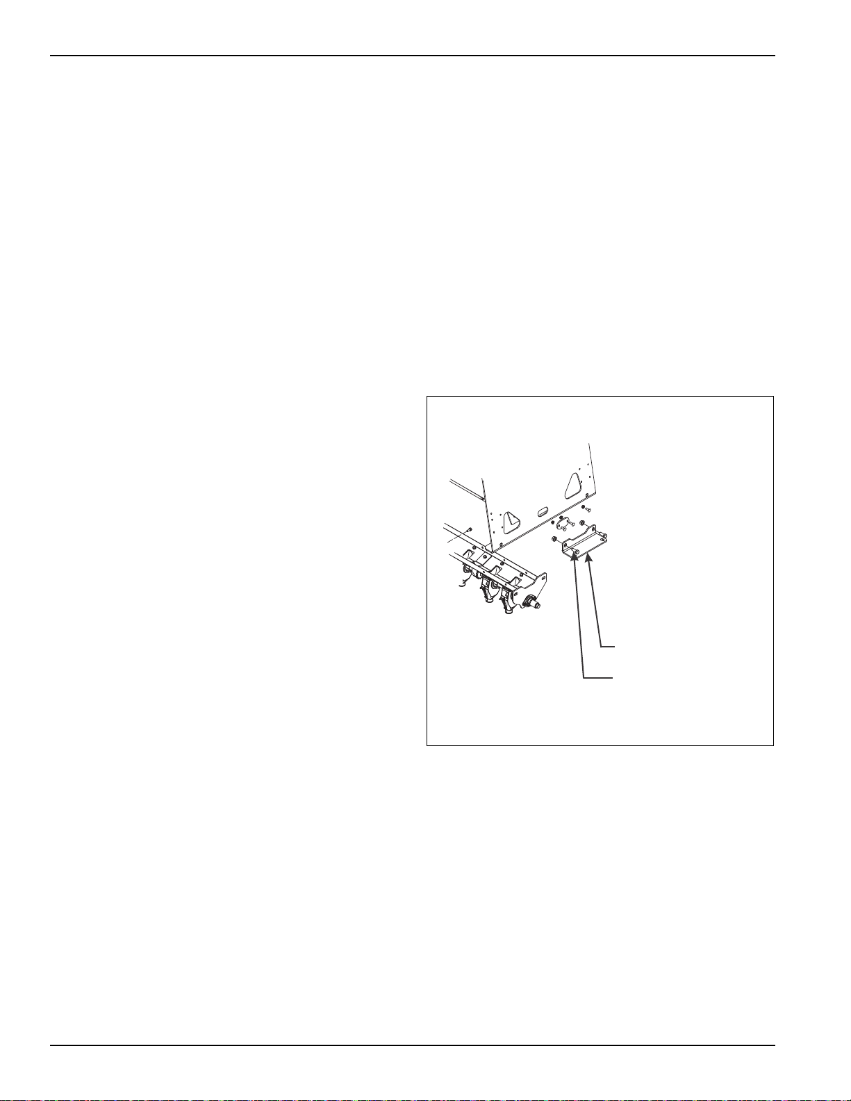
SEED BOX BRACKET
1/2-13 X 1-1/4 HEX
HEAD CAP SCREW
seed box bracket screw removal
Small Seed Attachment Installation (Option)
Refer to 3-2 for small seed attachment overview.
Use these instructions to install the optional small seed
attachment to the rear main seed box of 5531 Grain Drill.
1. Attach the drill to the tractor and lower the unit to the
ground. Leave the drill attached to the tractor while
assembling the small seed attachment. This will
prevent tipping of the drill while support stands are
removed.
2. Remove the SMV sign from the rear of the existing
seed box. Reinstall the mounting screws in the seed
box to plug the holes.
3. Determine whether the existing drill boxes have
mounting holes for the small seed attachment. See
Figure 2-9 for hole locations. If the mounting holes
do not exist, these holes must be drilled in existing
boxes before installing the attachment.
a. First locate and mark the center of the existing
seed box along the top rear box edge. Base all
dimensions from this mark.
b. Mark and center punch hole placement per
drawing.
c. Using a 13/32” diameter drill bit, drill the
mounting holes.
4. Remove the 3/8” hex lock nuts and 2-hole mounting
plates from the front of the small seed box assembly.
5. Carefully raise the small seed attachment and insert
the mounting screws through the holes drilled in the
rear of the main seed box. Inst all the 2-hole mounting
plates and 3/8” hex lock nuts on the inside of the
main drill box to secure the small seed attachment.
6. Remove the three outer locking nuts on the seed
shaft bearing assembly. Slide the bearing assembly
over the small seed square meter shaft. Insert the
bearing assembly mounting screws into the small
seed drive mount located on the end of the small
seed box assembly. Loosely install the three locking
nuts to hold the bearing assembly in place.
7. Just in front of the small seed bearing assembly,
remove the rear 1/2-13 x 1-1/4 hex head cap screw
from the existing seed box bracket (See Figure 3-3.)
3-4 F-716-1213 Edition
Figure 3-3: Removal of Rear Screw from Existing
Seed Box Bracket
Loading...