

Page 1

®
Chisel Plow
Mounted Models: CPP7-02 through CPP12-02
and CPP7-03 through CPP12-03
Operator’s Manual
LANDOLL CORPORATION
1900 North Street
Marysville, Kansas 66508
(785) 562-5381
800-428-5655 ~ WWW.LANDOLL.COM
175rev1113 7D525
Page 2

Page 3

1 Introduction and Safety Information
Introduction . . . . . . . . . . . . . . . . . . . . . . . . . . . . . . . . . . . . . . . . . . . . . . . . . . . . . . . . . . . . . . . . . . 1-1
Description of Unit . . . . . . . . . . . . . . . . . . . . . . . . . . . . . . . . . . . . . . . . . . . . . . . . . . . . . . . . . 1-1
Owner Assistance . . . . . . . . . . . . . . . . . . . . . . . . . . . . . . . . . . . . . . . . . . . . . . . . . . . . . . . . .1-1
Warranty Registration . . . . . . . . . . . . . . . . . . . . . . . . . . . . . . . . . . . . . . . . . . . . . . . . . . . . . .1-1
Safety . . . . . . . . . . . . . . . . . . . . . . . . . . . . . . . . . . . . . . . . . . . . . . . . . . . . . . . . . . . . . . . . . . . . . . . 1-2
Understanding Safety Statements . . . . . . . . . . . . . . . . . . . . . . . . . . . . . . . . . . . . . . . . . . . . . 1-2
Transporting Safety . . . . . . . . . . . . . . . . . . . . . . . . . . . . . . . . . . . . . . . . . . . . . . . . . . . . . . . . 1-2
Attaching, Detaching and Storage . . . . . . . . . . . . . . . . . . . . . . . . . . . . . . . . . . . . . . . . . . . . . 1-2
Maintenance Safety . . . . . . . . . . . . . . . . . . . . . . . . . . . . . . . . . . . . . . . . . . . . . . . . . . . . . . . .1-3
Protective Equipment . . . . . . . . . . . . . . . . . . . . . . . . . . . . . . . . . . . . . . . . . . . . . . . . . . . . . .1-3
Tire Safety . . . . . . . . . . . . . . . . . . . . . . . . . . . . . . . . . . . . . . . . . . . . . . . . . . . . . . . . . . . . . . . 1-3
Decals . . . . . . . . . . . . . . . . . . . . . . . . . . . . . . . . . . . . . . . . . . . . . . . . . . . . . . . . . . . . . . . . . . 1-4
Table of Contents
2 Assembly
Main Frame Assembly . . . . . . . . . . . . . . . . . . . . . . . . . . . . . . . . . . . . . . . . . . . . . . . . . . . . . . 2-1
Gage Wheels . . . . . . . . . . . . . . . . . . . . . . . . . . . . . . . . . . . . . . . . . . . . . . . . . . . . . . . . . . . . . 2-1
Frame Assembly Dimensions . . . . . . . . . . . . . . . . . . . . . . . . . . . . . . . . . . . . . . . . . . . . . . . . 2-2
Mast . . . . . . . . . . . . . . . . . . . . . . . . . . . . . . . . . . . . . . . . . . . . . . . . . . . . . . . . . . . . . . . . . . . . 2-3
Assembly of Chisel Plows . . . . . . . . . . . . . . . . . . . . . . . . . . . . . . . . . . . . . . . . . . . . . . . . . . . 2-5
Twisted Shovels . . . . . . . . . . . . . . . . . . . . . . . . . . . . . . . . . . . . . . . . . . . . . . . . . . . . . . . . . . 2-7
LED Warning Lights . . . . . . . . . . . . . . . . . . . . . . . . . . . . . . . . . . . . . . . . . . . . . . . . . . . . . . .2-8
LED Installation Instructions . . . . . . . . . . . . . . . . . . . . . . . . . . . . . . . . . . . . . . . . . . . . . . . . 2-13
3 Operation
General . . . . . . . . . . . . . . . . . . . . . . . . . . . . . . . . . . . . . . . . . . . . . . . . . . . . . . . . . . . . . . . . . 3-1
Operating Tips . . . . . . . . . . . . . . . . . . . . . . . . . . . . . . . . . . . . . . . . . . . . . . . . . . . . . . . . . . . . 3-1
4 Maintenance
General Torque Specifications . . . . . . . . . . . . . . . . . . . . . . . . . . . . . . . . . . . . . . . . . . . . . . . 4-1
Fasteners . . . . . . . . . . . . . . . . . . . . . . . . . . . . . . . . . . . . . . . . . . . . . . . . . . . . . . . . . . . . . . . 4-2
5 General Reference and Specifications
General . . . . . . . . . . . . . . . . . . . . . . . . . . . . . . . . . . . . . . . . . . . . . . . . . . . . . . . . . . . . . . . . . 5-1
7D525 i
Page 4

Page 5

Chapter 1
DANGER
Introduction and Safety Information
Introduction
The implement described in this manual has been
designed with care and built by skilled workers using
quality materials and processes. Proper assembly and
maintenance will provide you with satisfactory use for
seasons to come.
Read this entire manual before attempting to
assemble, adjust or operate this implement.
Failure to comply with this warning can result in
personal injury or death, damage
implement or its components and inferior
operation.
Description of Unit
The Chisel Plow was the machine that started the age of
“conservation tillage” as we know it today. The 3-Bar
Chisel Plows offer an effective and economic solution to
basic primary tillage. A wide variety of shank
configurations and points allow the producer to fine tune
the Chisel Plow to fit his requirements. Optional
extension kits allow the 3 Bar Chisel Plow to grow with
any operation.
to the
Owner Assistance
If customer service or repairs are needed, contact your
Brillion dealer. They have trained personnel, parts and
service equipment specially designed for Brillion
products. Your implement’s parts should only be replaced
with Brillion parts. If items covered in this manual are not
understood, contact your local Brillion Dealer.
Warranty Registration
Brillion Farm Equipment, by Landoll, shall have no
warranty obligation unless each product is registered
within 10 days of retail purchase, using the Landoll
Corporation Ag Products on-line registration process.
Please refer to the Ag Products Policy and Procedures
Manual, accessible at www.landoll.com
instructions regarding product registration.
Enter your product information below for quick reference.
MODEL NUMBER
SERIAL NUMBER
for step by step
Using this Manual
This manual will familiarize you with safety, assembly,
operation, adjustment, and maintenance. Read this
manual and follow the recommendations to help ensure
safe and efficient operation.
• The information in this manual is current at time of
printing. Some parts may have changed to assure top
performance.
• Location reference: Right and Left designations in this
manual are determined by facing the direction the
implement will travel during field operation, unless
otherwise stated.
DATE OF PURCHASE
Refer to the ID plate as shown. See Figure 1-1.
Figure 1-1: ID Plate
1-1
Page 6

INTRODUCTION AND SAFETY INFORMATION
NOTE
NOTICE
CAUTION
WARNING
DANGER
NOTE
DANGER
IMPORTANT
Safety
Investigation has shown that nearly 1/3 of all farm
accidents are caused by careless use of machinery.
Insist that all people working with you or for you abide by
all safety instructions.
Understanding Safety Statements
You will find various types of safety information on the
following pages and on the implement decals (signs)
attached to the implement. This section explains their
meaning.
Special notice - read and thoroughly understand.
Proceed with caution. Failure to heed caution
may
cause injury to person or damage product.
Proceed with caution. Failure to heed warning will
cause injury to person or damage product.
Proceed with extreme caution. Failure to heed
notice will cause injury or death to person and/or
damage product.
You should read and understand the information
contained in this manual and on the implement decals
before you attempt to operate or maintain this equipment.
Examine safety decals and be sure you have the correct
safety decals for the implement. See Figure 1-2.
Order replacement decals through your Brillion dealer.
Keep these signs clean so they can be observed readily.
It is important to keep these decals cleaned more
frequently than the implement. Wash with soap and water
or a cleaning solution as required.
Replace decals that become damaged or lost. Also, be
sure that any new implement components installed
during repair include decals which are assigned to them
by the manufacturer.
When applying decals to the implement, be sure to clean
the surface to remove any dirt or residue. Where
possible, sign placement should protect the sign from
abrasion, damage, or obstruction from mud, dirt, oil etc.
• Do not allow anyone to ride on the tractor or
implement. Riders could be struck by foreign
objects or thrown from the implement.
• Never allow children to operate equipment.
• Keep bystanders away from implement during
operation.
Transporting Safety
It is the responsibility of the owner/operator to
comply with all state and local laws.
When transporting the implement on a road or highway,
use adequate warning symbols, reflectors, lights and
slow moving vehicle sign as required. Slow moving
tractors and towed implements can create a hazard when
driven on public roads. They are difficult to see,
especially at night.
Do not tow an implement that, when fully loaded, weighs
more than 1.5 times the weight of the towing vehicle.
Carry reflectors or flags to mark the tractor and
implement in case of breakdown on the road.
Do not transport at speeds over 20 MPH under good
conditions. Never travel at a speed which does not allow
adequate control of steering and stopping. Reduce
speed if towed load is not equipped with brakes.
Avoid sudden stops or turns because the weight of the
implement may cause the operator to lose control of the
tractor. Use a tractor heavier than the implement.
Use caution when towing behind articulated steering
tractors; fast or sharp turns may cause the implement to
shift sideways.
Keep clear of overhead power lines and other
obstructions when transporting. Know the transport
height and width of your implement.
Attaching, Detaching and Storage
• Do not stand between the tractor and implement when
attaching or detaching implement unless both are
blocked from moving.
• Block implement so it will not roll when unhitched from
the tractor.
1-2 7D525
Page 7

INTRODUCTION AND SAFETY INFORMATION
Maintenance Safety
• Block the implement so it will not roll when working on
or under it to prevent injury.
• Do not make adjustments or lubricate the machine
while it is in motion.
• Make sure all moving parts have stopped.
• Understand the procedure before doing the work. Use
proper tools and equipment.
Protective Equipment
• Wear protective clothing & equipment appropriate for
the job. Avoid loose fitting clothing.
• Because prolonged exposure to loud noise can cause
hearing impairment or hearing loss, wear suitable
hearing protection, such as earmuffs or earplugs.
Tire Safety
Tire changing can be dangerous and should be
performed by trained personnel using correct tools and
equipment.
When inflating tires, use a clip-on chuck and extension
hose long enough to allow you to stand to one side, not in
front of or over the tire assembly. Use a safety cage if
available.
When removing and installing wheels use
wheel-handling equipment adequate for the weight
involved.
1-3
Page 8

INTRODUCTION AND SAFETY INFORMATION
528933
528934
CAUTION
1. DO NOT LUBRICATE, ADJUST OR REPAIR WHEN MACHINE IS IN MOTION.
2. DO NOT TOW OR TRANSPORT FASTER THAN 15 MILES PER HOUR.
3. DO NOT RIDE OR ALLOW OTHERS TO RIDE ON THE MACHINE.
4. BLOCK UP ALL HYDRAULICALLY OR MECHANICALLY RAISED COMPONENTS TO PREVENT
UNINTENDED LOWERING OR LOWER THE MACHINE TO THE GROUND TO MAKE ADJUSTMENT
OR REPAIRS OR WHEN NOT IN USE.
5. KEEP ALL PERSONS AWAY FROM MACHINE DURING HITCHING AND OPERATING.
6. SLOW DOWN BEFORE MAKING SHARP TURNS OR USING THE BRAKE.
DRIVE SLOWLY OVER ROUGH GROUND, SIDE HILLS, AND AROUND CURVES TO AVOID TIPPING.
7. COMPLY WITH ALL LAWS WHEN TRANSPORTING THE MACHINE ON PUBLIC ROADWAYS.
8. INSTRUCT ALL OPERATORS IN THE SAFE OPERATION OF THE MACHINE.
REVIEW THE OPERATOR’S MANUAL FOR CORRECT PROCEDURES.
9. BLOCK IMPLEMENT TO PREVENT MOVEMENT WHEN UNHITCHED FROM TRACTOR.
10. KEEP ALL GUARDS AND SHIELDS IN PLACE WHILE MACHINE OR PARTS ARE IN MOTION.
8J310
8J310
4K036
Remove Stripe
here to fit.
1
4
2
3
3
4
2
4
2
4
Name Plate
4
2
4
2
4
3
1
Decals
Figure 1-2: Decals and Locations
1-4 7D525
Page 9

CAUTION
Do not work on or under this machine unless
securely
tractor or by other sufficient means.
blocked and supported by a hoist or
Main Frame Assembly
1. Assemble the 7D456 mast assembly and 7D462
plate to the main frame using the 5/8 x 6” bolts, nuts
and lockwashers provided. Do not draw bolts up tight
at this time.
2. Assemble the Left Hand brace assembly and Right
Hand brace assembly to the mast and the pads on
the rear frame tube. The 1” x 6” bolt fastens both
braces to the top set of holes in the mast. The 6D998
pipe spacer is used over this bolt. Use the 3/4 x
2-1/2” bolts to attach the other ends of the braces to
the frame. Now, all the bolts can be drawn tight.
3. Place the frame on blocks at least 10 inches high for
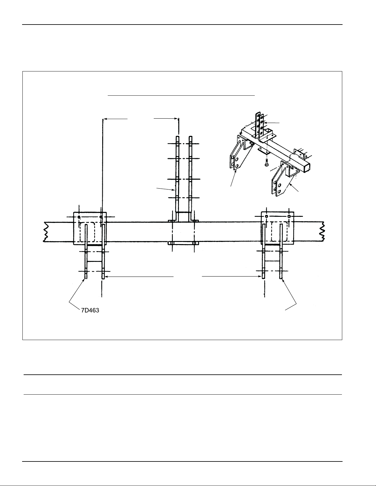
the assembly of the hitch brackets. See figure 2-1
and determine the bracket spacings to be used with
the corresponding Category II or III tractor available.
4. When a Category II is used, mount the 7D463 right
hand and 7D464 left hand brackets with the plates for
attaching tractor links offset toward center of
machine.
5. For Category III tractors, mount brackets with plates
for attaching tractor links offset to outside. Assemble
the 7D470 left hand and 7D471 right hand angles to
their mating brackets using 5/8-11 x 4-1/2” bolts and
5/8 x 6” bolts with lockwashers and nuts provided.
Fasten bolts securely.
The 5D157 mast sleeve is to be used on tractors with
Category III. The 5D158 brackets sleeves are used on
tractors with Category III.
When mounting implement to tractor linkage, the upper
set of holes in the 7D463 and 7D464 bracket assemblies
are used with 26” shanks. The lower set of holes are
used with 32” shanks.
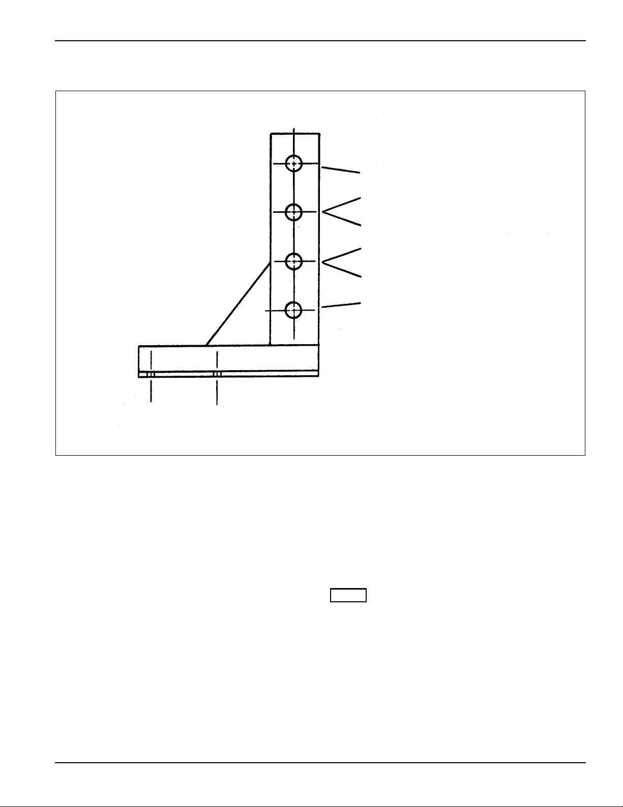
The holes in the 7D456 mast to be used will vary with the
different tractor categories available. See Figure 2-2.
Tighten all hardware to the recommended torques. See
Page 4-1.
Chapter 2
Assembly
Gage Wheels
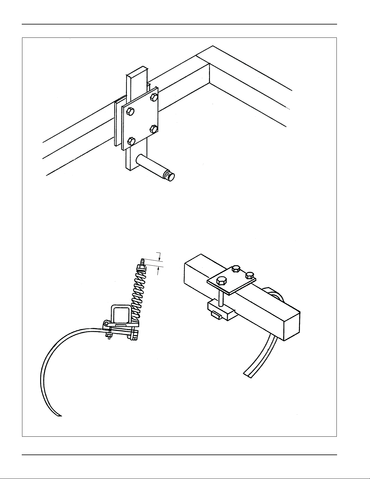
Figure 3 shows how the gage wheels are assembled to
the frame, if your is so equipped.
To adjust gage wheel, loosen the four 5/8 x 3” bolts, but
do not remove nuts. Set wheels to desired height so that
both wheels are set at the same depth. The distance
from the bottom of the tire to the tip of the shank will be
the approximate working depth of the shank. Tighten all
hardware to the recommended torques and check
periodically for looseness. See Page 4-1.
2-1
Page 10
ASSEMBLY
7D456
7D463
7D464
DIM. “B”
7D456
DIM. “A”
7D464
Front View of Machine with Mast and Bracket Spacing
Frame Assembly Dimensions
“Left” and “Right” refer to directions seen as if standing
behind the machine and facing in the direction of forward
travel.
Figure 2-1: Frame Assembly Dimensions
Frame
Assembly
7’ and 10’ 26” and 32” II (Two)
7’ and 10’ 26” and 32” II (Three)
Shank
Size
Category
Used
Dimension
“A”
32-3/8”
(Shown)
37-16/16”* 17-15/16”*
Dimension
“B”
15-1/8”
(Shown)
* To obtain this dimension, mount L.H. Bracket Assembly
on the R.H. side of machine and R.H. Bracket Assembly
on L.H. side of machine.
2-2 7D525
Page 11
Mast
NOTE
Category III Free Link - 26” Shanks
Category II Free Link - 26” Shank
Category III Free Link - 32” Shank
Category III Quick Coupler - 26” Shank
Category II Quick Coupler - 26” Shank
Category III Quick Coupler - 32” Shank
Category II Free Link - 32” Shank
Category II Quick Coupler - 32” Shank
ASSEMBLY
Figure 2-2: Mast
The rigid mounted shanks are shipped assembled to the
shank clamps. To mount these on the chisel plow,
remove the 3/4” bolt and nut from the front of the
assembly.
Slide the assembly onto the tooth bar and replace the
bolt and nut. See Figure 2-3 for assembly and location of
shanks.
To mount the shank to the clamp, first remove the nut
from the 3/4 x 3-1/2” bolt and remove the bolt from the
shank holder and from the U-bolt clip.
Loosen the two nuts on the small U-bolt so that the shank
can slide between the plate and the shank holder.
Remove the two locknuts from the long U-bolt and
remove the plate and spring caps.
Slide the shank between the legs of the small U-bolt and
between the plate and the shank holder and also
between the legs of the long U-bolt. Insert the 3/4” bolt
through the shank holder, the shank and the U-bolt clip.
Assemble the spring caps, the plate and the two locknuts
on the long U-bolt making sure the U-bolt is positioned
correctly in the U-bolt clip.
Tighten all nuts. Mount the assembly to the toothbar.
Torque the 3/4” nuts to 200 ft. lbs.
For field operation, the spring bolts should be tightened
so that one inch of thread is exposed as shown in Figure
2-3.
For chisel plowing tougher ground you may want to clamp
the spring tighter.
When this is done, the shank and tooth will not pass over
as great as obstruction.
2-3
Page 12
ASSEMBLY
Spring Cushion
Shank Clamp
Rigid Shank
Clamp
5/8 x 3” Bolts,
Nuts, and Lockwashers
1”
Figure 2-3: Rigid and Spring Clamp
2-4 7D525
Page 13
Assembly of Chisel Plows
36”
24”
36”
12”
24”
24”
36”
36”
36”
36”
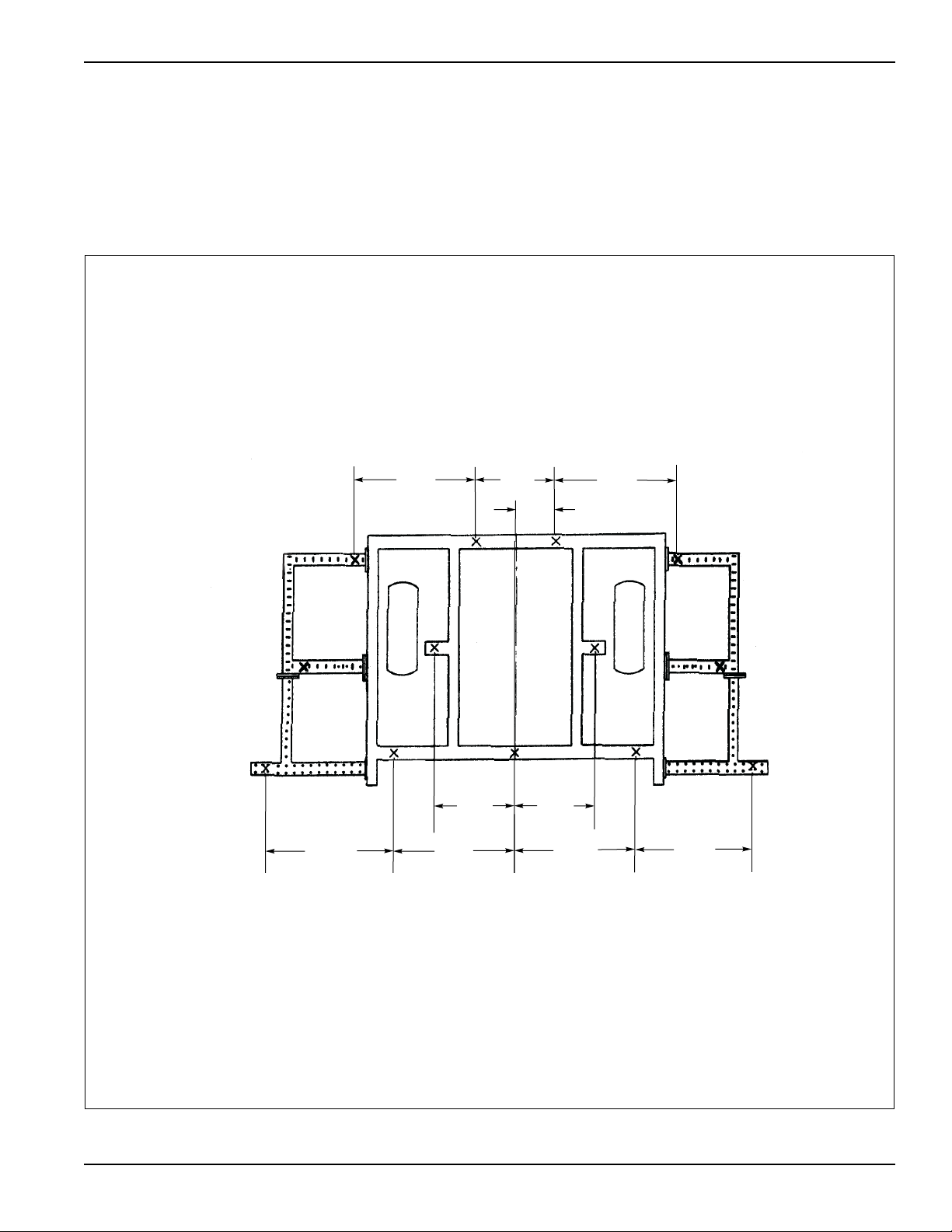
After the basic 7 foot frame is assembled for the 9 foot
and 11 foot or the basic 10 foot frame for the 12 foot
models. Then add on the extensions as illustrated in the
following pages. In Figure 2-4 the dashed portion
represents the 2 foot extension and the dotted portion
represents the additional section added to extend 3 feet.
ASSEMBLY
Figure 2-4: Frame Extensions
2-5
Page 14
ASSEMBLY
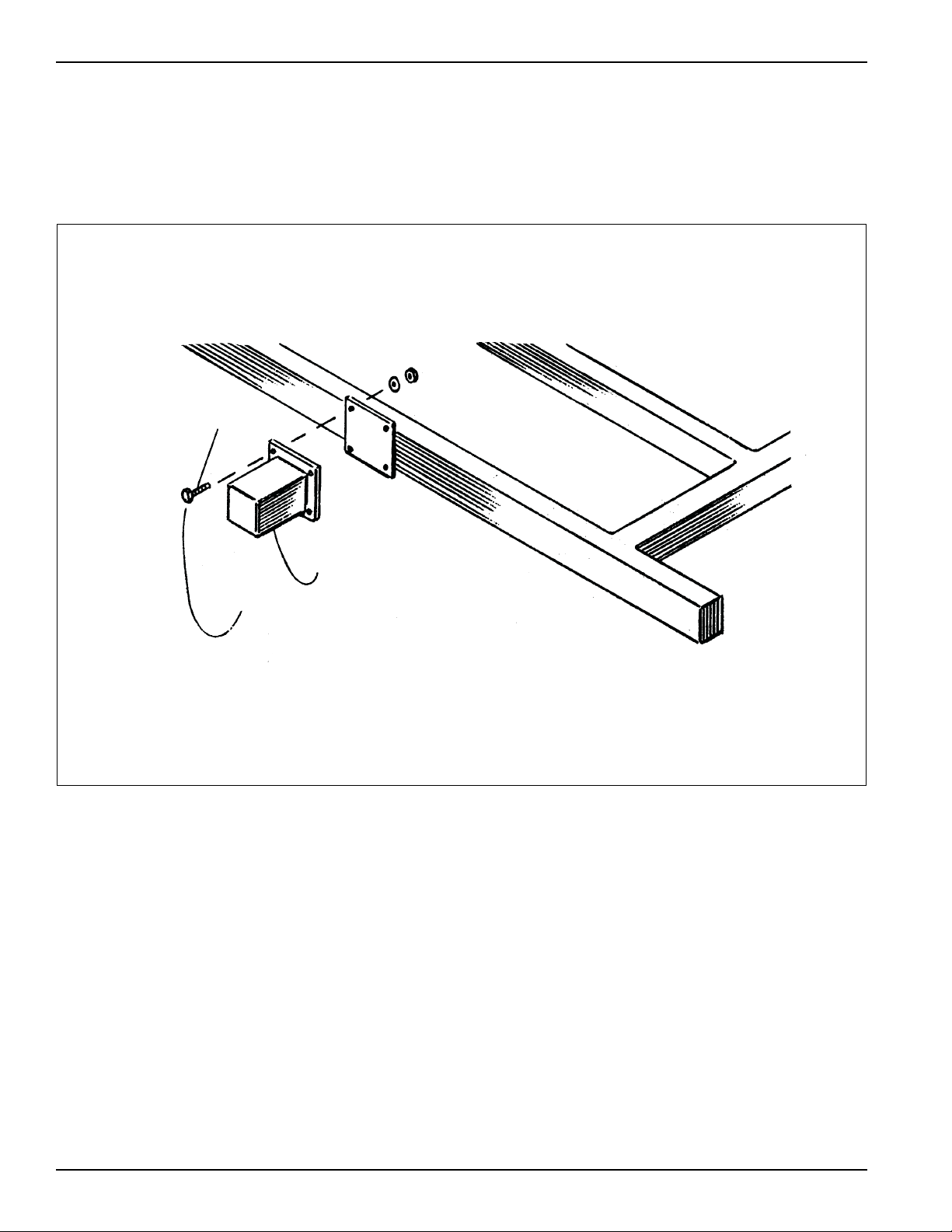
5/8” x 2”
Bolt Head to Outside
One Foot Extension
To make 9 foot and 12 foot machines the one foot
extension is assembled to the basic 7 foot or 10 foot
machine. See Figure 2-5. On the 9 foot and 12 foot
machines the outermost shanks are attached to the one
foot extensions.
To assemble an 11 foot machine, bolt a two foot
extension to each side of the main frame as shown in
Figure 2-5, using 5/8” x 2” bolts on the front. The front
part of the extension and the plate attached to it are used
to clamp onto the front to rear tubing. Make sure the bolt
heads are to the outside of the main frame.
Figure 2-5: One Foot Extension
2-6 7D525
Page 15
Twisted Shovels
NOTE
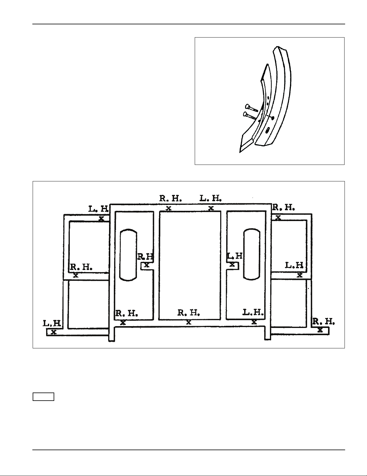
If twisted shovels are to be used, it is suggested that they
be arranged on the shanks as shown in Figure 2-7. (L.H.
means that the soil is thrown left and R.H. means that the
soil is thrown to the right.) If another arrangement is
desired, be sure that the shovels have balanced positions
from right side to left; i.e., a L.H. shovel is the same
distance from the center of the machine as a R.H. shovel
is on the opposite side. Place the plow bolts in the bottom
holes of the shovel as shown in Figure 2-6.
ASSEMBLY
Figure 2-6: Twisted Shovels
Figure 2-7: Shovel Arrangement 7’ Main Frame
The shank clearance, 26”, refers to the distance from the
bottom of the straight portion of the shank to the bottom
point on a regular reversible chisel point which is new.
See Figure 2-3.
When replacing or reversing points, change all points at
the same time so that they will have the same operating
depth. If some shanks have worn points, or points of a
different design, the chisel plow will not operate
efficiently.
2-7
Page 16
ASSEMBLY
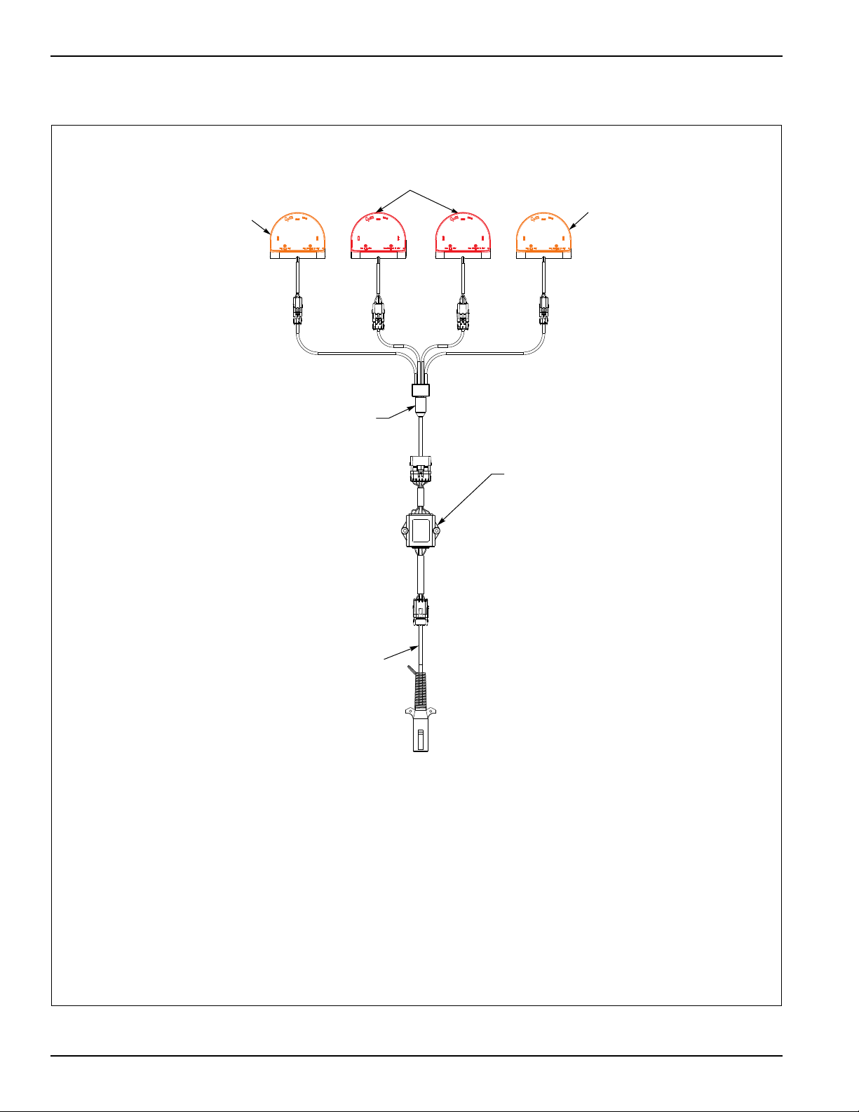
Amber LED Lamp
LED Warning
Lights Harness
Flasher Control
Module
7Pin/4Pin
WP Harness
Red LED Lamp
Amber LED Lamp
When plugging in the LED 7-pin connector:
1) Make sure the tractor has a good clean receptacle, free of dirt and corrosion.
2) Make sure the 7-pin connector is inserted ALL the way in. With tighter fitting pins, operator
maLJ think the connector is all the way in, but really isn’t.
3) Make sure the tractor receptacle cover latches over the keyway on the 7-pin connector to hold
the connector in place.
If an operator plugs in the 7-pin connector, but the lights do not seem to work right, check the above
items to make sure there is a good connection with the 7-pin connector.
LED Warning Lights
Figure 2-8: LED Warning Lights
2-8 7D525
Page 17
ASSEMBLY
17 1/2"
(11 Shank)
17 1/2"
(11 Shank)
4"
17"
C
L
Front View
11 Shank Machine Shown
LH
SMV
Light
Bracket
Amber
Lamp
Red
Lamp
SMV
Bracket
RH
Module
Bracket
Red
Lamp
Amber
Lamp
Light
Bracket
(7,9,11 Shank)
12"
(7,9,10,12 Shank)
12"
(7,9,10,12 Shank)
4"
7 3/8"
C
L
Front View
12 Shank Machine Shown
LH
Light
Bracket
Amber
Lamp
Red
Lamp
SMV
SMV
Bracket
RH
Module
Bracket
Light
Bracket
Amber
Lamp
Red
Lamp
(10,12 Shank)
CPP7-12 OpElectDim
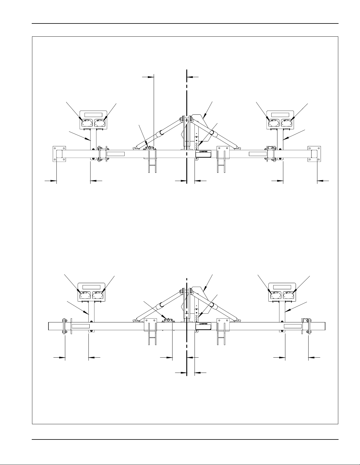
Figure 2-9: Electrical Installation Dimensions
2-9
Page 18
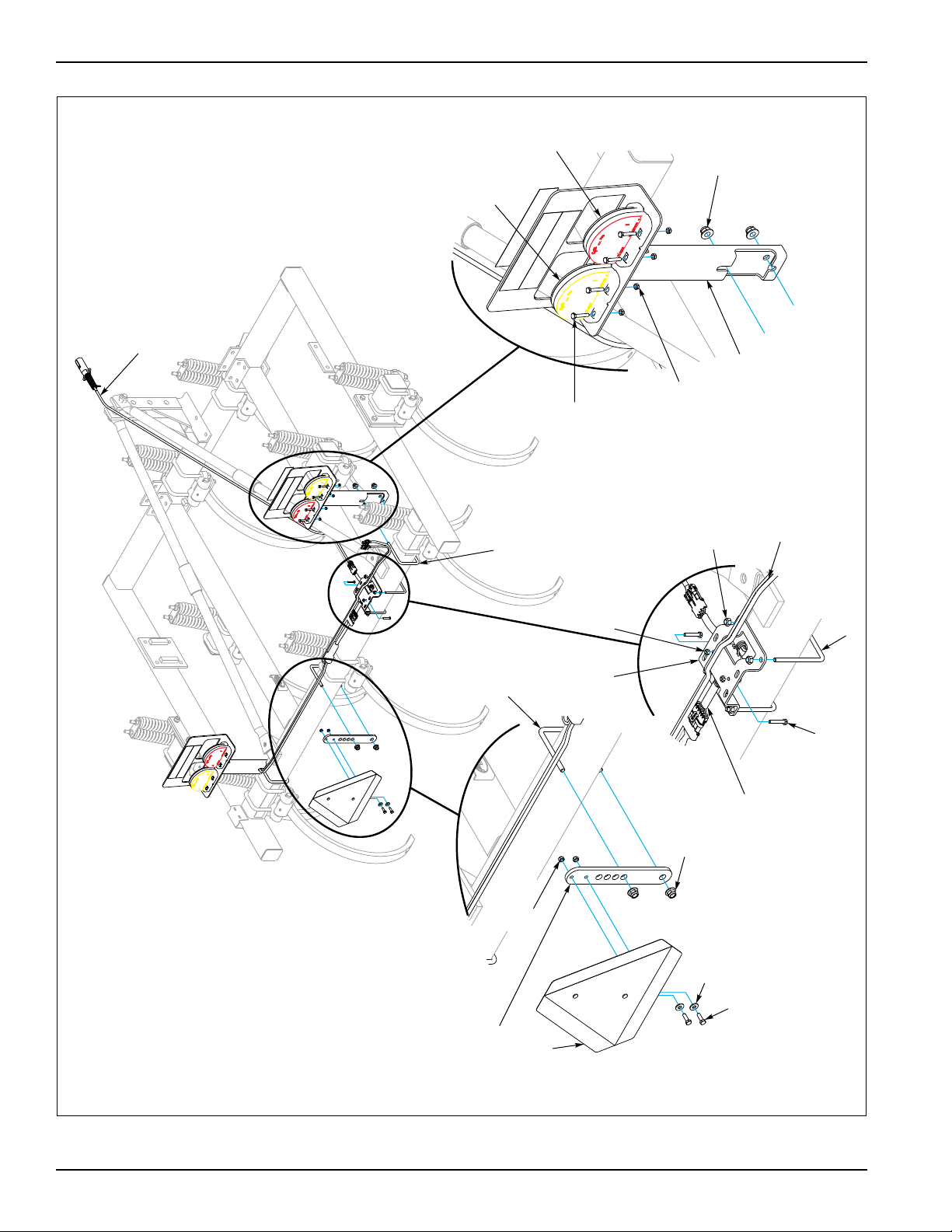
ASSEMBLY
CPP7&9 ElectLayout
SMV
Amber
LED
Red
LED
Bolt,1/4-20 x 1-1/2
Nut,1/4-20
7 Pin Harness
U-Bolt,1/2-13
U-Bolt,3/8-16
Bolt,5/16-18 x 1
Flat Washer,5/16
Nut,3/8-16
SMV
Mount
Nut,5/16-18
Bolt,1/4-20 x 1-1/2
Nut,1/4-20
Light Module
Module
Mount
U-Bolt,3/8-16
Nut,1/2-13
Light
Bracket
Lamp
Harness
Nut,3/8-16
Figure 2-10: 7’ and 9’ LED Warning Lights Layout
2-10 7D525
Page 19
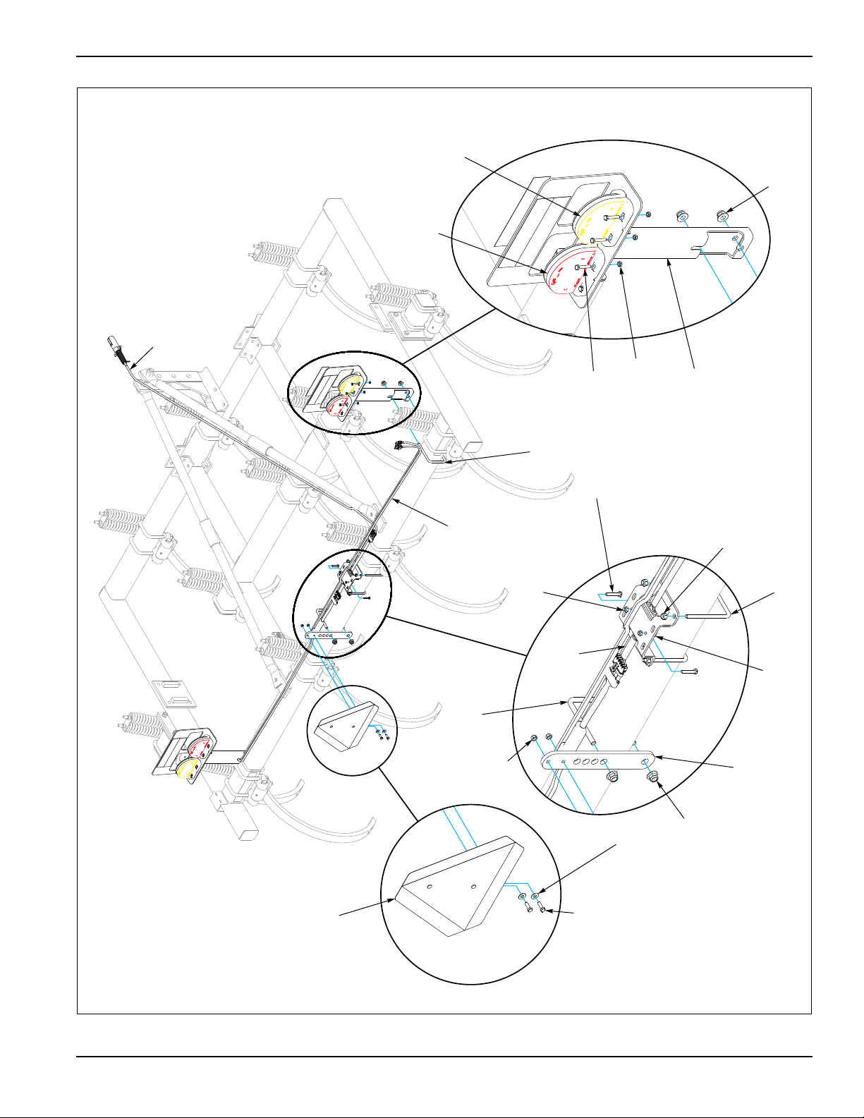
Nut,1/4-20
7 Pin Harness
Lamp
Harness
Light
Bracket
Bolt,1/4-20 x 1-1/2
Nut,1/2-13
Red
LED
Amber
LED
SMV
Bolt,5/16-18 x 1
Flat Washer,5/16
Light
Module
Nut,1/4-20
SMV
Mount
U-Bolt,3/8-16
Nut,5/16-18
U-Bolt,1/2-13
Nut,3/8-16
Light
Bracket
U-Bolt,3/8-16
Nut,3/8-16
ASSEMBLY
Figure 2-11: 10’ and 12’ LED Warning Lights Layout
2-11
Page 20
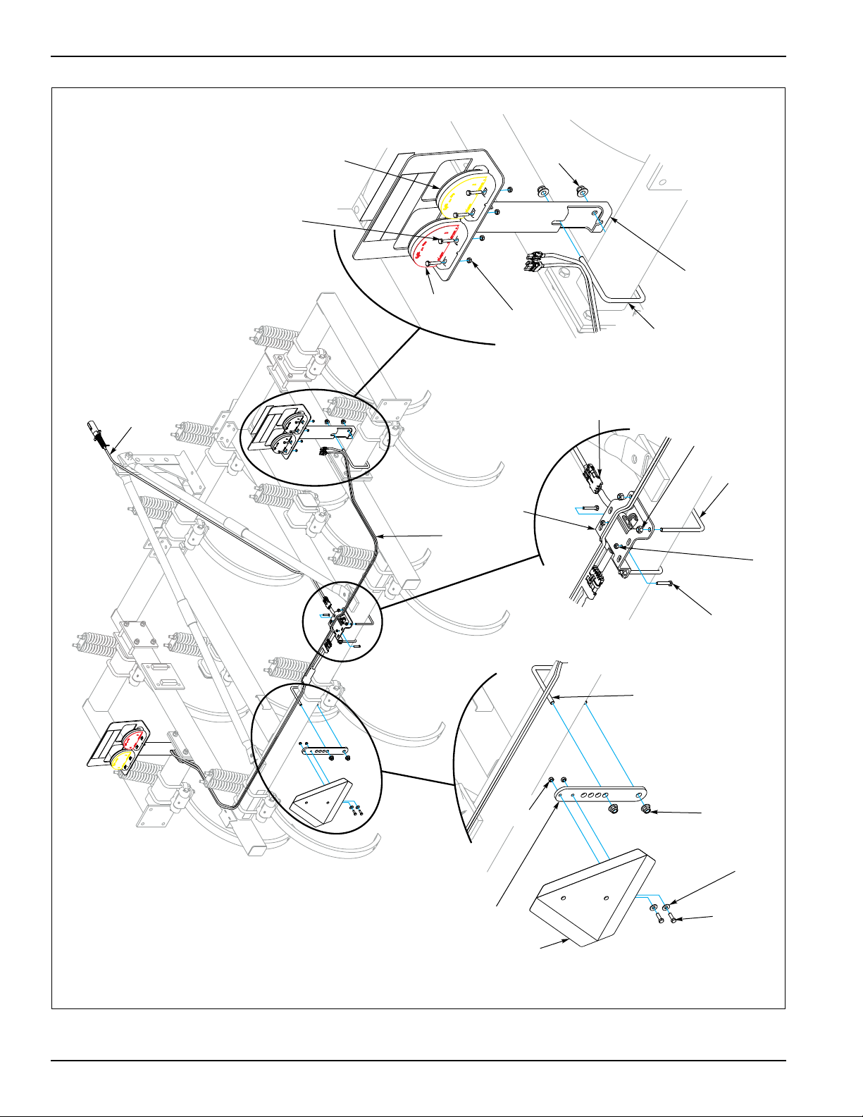
ASSEMBLY
CPP11 ElectLayout
SMV
SMV Mount
Bolt,5/16-18 x 1
Flat Washer,5/16
Nut,3/8-16
Nut,5/16-18
U-Bolt,3/8-16
Lamp
Harness
Module Bracket
Light
Module
U-Bolt,3/8-16
Bolt,
1/4-20 x 1-1/2
Nut,1/4-20
Nut,3/8-16
7 Pin Harnes
Red
LED
Amber
LED
Nut,1/4-20
Bolt,1/4-20 x 1-1/2
Light
Bracket
U-Bolt,1/2-13
Nut,
1/2-13
Figure 2-12: 11’ LED Warning Lights Layout
2-12 7D525
Page 21

ASSEMBLY
NOTE
LED Installation Instructions
All models similar. Refer to Figure 2-9 for bracket and
light placement.
1. Attach the 2 (two) Light Brackets to the rear frame
using the 1/2-13 U-Bolts and Nuts. On the 11’ Models
the Light Brackets are attached the 2 (two) foot
extensions. See Figures 2-10, 2-11, and 2-12.
2. Attach Amber LED to the outside of the Light Bracket
using (4) 1/4-20 x 1 1/4 Screws and Locknuts, then
attach the Red LED next to the Amber LED using (4)
1/4-20 x 1 1/4 Screws and Locknuts
3. Attach the Light Module to the Module Bracket using
(2) 1/4-20 x 1 1/2 Screws and Locknuts.
4. Attach the Module Bracket to the top of the rear
frame using 2 (two) 3/8-16 U-Bolts and Nuts.
5. Attach the SMV Mount to the rear frame using 1
(one) 3/8-16 U-Bolt and Nuts. Then attach the SMV
Sign to the Mount using (2) 5/16-18 x 1 Screws, Flat
Washers, and Locknuts.
6. Layout the Lamp Harness, noting that the connectors
marked with Green Tape is Right Side and Yellow
Tape is Left Side.
7. Plug the Lamp Harness into the Light Module, route
both cord plugs with Green Tape along the top right
side of the rear frame. Route the plugs up through
the Light Bracket and plug the 3 prong cord into the
Red LED. Plug the 2 prong cord into the Amber LED.
8. On the 11’Model, route both cord plugs with Green
Tape along the top right side of the rear frame. then
up the outer right frame, then over to the 2’extension.
Route the plugs up through the Light Bracket and
plug the 3 prong cord into the Red LED. Plug the 2
prong cord into the Amber LED.
9. Repeat for the Left Side (Yellow Tape).
10. Plug the 7 Pin Harness into the Light Module, then
route the harness along the Right Hand Brace and
secure with Tie Straps.
11. Bundle and secure excess cord to the Module
Bracket with Tie Straps. Secure cords along frame
and brace using Tie Straps.
All wires must be firmly attached to machine frame
members so they do not sag or become torn loose by
field debris.
2-13
Page 22

ASSEMBLY
Table provided for general use.
NOTES:
2-14 7D525
Page 23
Chapter 3
NOTE
NOTE
Operation
This chapter will cover the basic operation and
procedures for the Landoll Brillion Chisel Plow. Be sure to
read and understand the Safety Procedures and
Cautions starting on See Page 1-1.
General
• The chisel plow loosens the soil to the desired depth,
allowing water penetration into the soil. During the
winter, the ground will freeze deeper and “weather
out” much faster.
• Chisel plowing leaves a mulch and residue cover on
the surface, preventing soil surface sealing. Water
will be absorbed quickly into the soil, reducing runoff,
evaporation and soil erosion. The residue cover also
reduces wind erosion.
Operating Tips
• To retard downhill water movement on slopes, start at
the bottom of the slope and work upwards, parallel to
the bottom.
• Chisel the field at an angle to the rows to break up
the ridges.
Before operating your Brillion machine, check all
hardware for tightness. Use the Tightening Torque Table
in Chapter 4 as a guide. See Page 4-1.
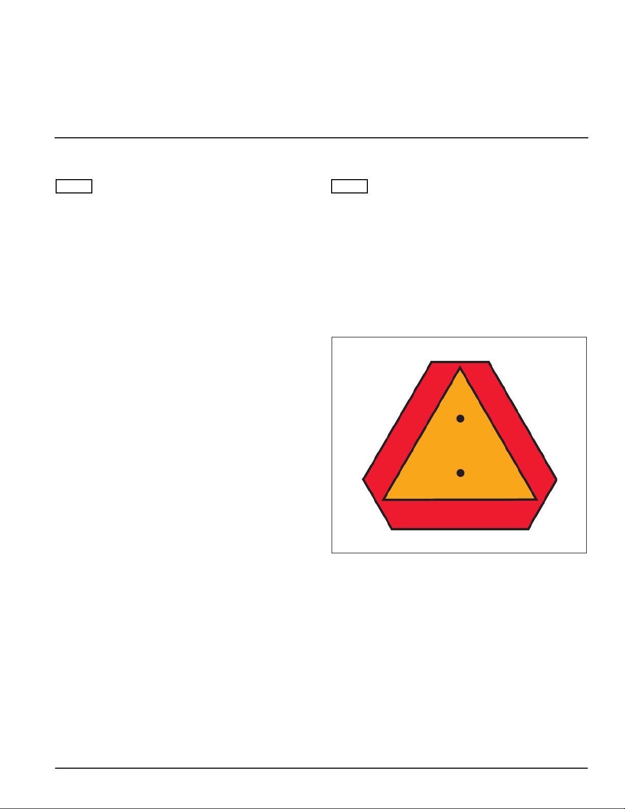
Reflectors and SMV Sign
Reflectors and a slow moving vehicle sign (SMV) are
required if the Chisel Plow is transported on a public
road. See Figure 3-1.
Operating Speed
• The chisel works best when operated at a relatively
fast speed; 5 mph or faster. If field conditions are
adverse, operate at a slower speed to reduce the
possibility of implement damage.
• If field conditions are too rough to operate at high
speed at the desired depth, make two passes at an
angle to each other. Make the first pass shallower
than the second pass.
Figure 3-1: SMV Sign
3-1
Page 24

OPERATION
Table provided for general use.
NOTES:
3-2 7D525
Page 25

Chapter 4
Maintenance
General Torque Specifications
(rev. 4/97)
This chart provides tightening torques for general purpose applications when special torques are not specified on process or
drawing. Assembly torques apply to plated nuts and capscrews assembled without supplemental lubrication (as received condition).
They do not apply if special graphite moly-disulfide or other extreme pressure lubricants are used. When fasteners are dry (solvent
cleaned) add 33% to as received condition torque. Bolt head identification marks indicate grade and may vary from manufacturer to
manufacturer. Thick nuts must be used on grade 8 capscrews. Use value in [ ] if using prevailing torque nuts
TORQUE SPECIFIED IN FOOT POUNDS
UNC
SIZE
1/4-20 4 [5] 6 [7] 9 [11] 1/4-28 5 [6] 7 [9] 10 [12]
5/16-18 8 [10] 13 [13] 18 [22] 5/16-24 9 [11] 14 [17] 20 [25]
3/8-16 15 [19] 23 [29] 35 [42] 3/8-24 17 [21] 25 [31] 35 [44]
7/16-14 24 [30] 35 [43] 55 [62] 7/16-20 27 [34] 40 [50] 60 [75]
1/2-13 35 [43] 55 [62] 80 [100] 1/2-20 40 [50] 65 [81] 90 [112]
9/16-12 55 [62] 80 [100] 110 [137] 9/16-18 60 [75] 90 [112] 130 [162]
5/8-11 75 [94] 110 [137] 170 [212] 5/8-18 85 [106] 130 [162] 180 [225]
3/4/10 130 [162] 200 [250] 280 [350] 3/4-16 150 [188] 220 [275] 320 [400]
7/8-9 125 [156] 320 [400] 460 [575] 7/8-14 140 [175] 360 [450] 500 [625]
1-8 190 [237] 408 [506] 680 [850] 1-14 210 [263] 540 [675] 760 [950]
1-1/8-7 270 [337] 600 [750] 960 [1200] 1-1/8-12 300 [375] 660 [825] 1080 [1350]
1-1/4-7 380 [475] 840 [1050 1426 [1782] 1-1/4-12 420 [525] 920 [1150] 1500 [1875]
1-3/8-6 490 [612] 1010 [1375] 1780 [2225] 1-3/8-12 560 [700] 1260[1575] 2010 [2512]
1-1/2-6 650 [812] 1460 [1825] 2360 [2950] 1-1/2-12 730 [912] 1640[2050] 2660 [3325]
METRIC:
Coarse thread metric class 10.9 fasteners and class 10.0 nuts and through hardened flat washers, phosphate coated, Rockwell “C”
38-45. Use value in [ ] if using prevailing torque nuts
Nominal
thread
diameter (mm)
SAE
Grade 2
Newton Meters
SAE
Grade 5
(Standard
Torque)
SAE
Grade 8
Foot Pounds
(Standard
Torque)
UNF
SIZE
Nominal Thread
Diameter (mm)
Grade 2
SAE
Newton Meters
(Standard
Torque )
SAE
Grade 5
SAE
Grade 8
Foot Pounds
(Standard
Torque
6 10 [14] 7 [10] 20 385 [450] 290 [335]
7 16 [22] 12 [16] 24 670 [775] 500 [625]
8 23 [32] 17 [24] 27 980 [1105] 730 [825]
10 46 [60] 34 [47] 30 1330 [1470] 990 [1090]
12 80 [125] 60 [75] 33 1790 [1950] 1340 [1450]
14 125 [155] 90 [115] 36 2325 [2515] 1730 [1870]
16 200 [240] 150 [180] 39 3010 [3210] 2240 [2380]
18 275 [330] 205 [245]
4-1
Page 26

MAINTENANCE
Fasteners
Before operating your Brillion machine, check all
hardware for tightness. Use the Tightening Torque Table
below as a guide. See Page 4-1.
After a few hours of use, check entire machine and
tighten any loose nuts or bolts. Daily or periodic checks
should be made thereafter.
When replacing bolts, be sure to use fasteners of equal
grade.
Beginning Of Day
• Check for and tighten any loose U-bolts holding
spring clamps to frame. See Torque Chart.
End of Day
• Clean dirt and residue from implement.
• Check for and repair any equipment damage.
Beginning of Season
• Perform end-of-season lubrication.
• Tighten all loose bolts, U-bolts.
• Check torque settings on spring cushion clamps.
End of Season
• Clean all dirt and residue from implement.
• Repair or replace any damaged parts.
• Clean and paint all areas where paint is chipped or
worn away.
• Replace missing or damaged decals.
• Store implement in a clean, dry area away from
livestock.
• Lower implement with wooden blocks under chisels
to keep off concrete floors or bare ground.
• Park implement in level position so all chisels support
weight of implement.
4-2 7D525
Page 27

Chapter 5
General Reference and Specifications
General
Shanks.........................................1” x 2” x 26” Clearance
1 1/4” x 2” x 32” Clearance
Shank Spacing................................................One Foot
Model Number Number of Shanks 3 Point Lift
CPP-7 7 CAT. II and CAT. III
CPP-9 9
CPP-10 10
CPP-11 11
CPP-12 12 CAT. II and CAT. III Quick Coupler
Working Depth.....................................................0 to 12”
Gage Wheel Rims..........................................15” - 5 Bolt
5-1
Page 28

GENERAL REFERENCE AND SPECIFICATIONS
Table provided for general use.
NOTES:
5-2 7D525
Page 29

Document Control Revision Log:
Date Revision Improvement(s) Description and Comments
07/2001 Initial Release
11/2013 175rev1113 Updated to the Landoll format. Added LED Warning Lights
Page 30

Equipment from Landoll Corporation is built to exacting
standards ensured by ISO 9001:2008 registration at all
Landoll manufacturing facilities.
Chisel Plow
Mounted Models: CPP7-02 through CPP12-02
and CPP7-03 through CPP12-03
Operator’s Manual
Re-Order Part Number 7D525
LANDOLL CORPORATION
1900 North Street
Marysville, Kansas 66508
(785) 562-5381
800-428-5655 ~ WWW.LANDOLL.COM
®
Copyright 2013. Landoll Corporation
"All rights reserved, including the right to reproduce this material or portions thereof in any form.”
175rev1113 7D525
- Author Tech Comm Bill
 Loading...