

Page 1
Model 2000 Series
Row Crop Cultivator
Operator’ s Manual
LANDOLL CORPORATION
1900 North Street
Marysville, Kansas 66508
(785) 562-5381
800-428-5655 ~ WWW.LANDOLL.COM
F-140-0512 05/2012
Page 2

Page 3

1 Introduction
Understanding Safety Statements . . . . . . . . . . . . . . . . . . . . . . . . . . . . . . . . . . . . . . . . . . . . . . . . 1-2
2 Standard Specifications
3 Assembly Instructions
Assembly Preparation . . . . . . . . . . . . . . . . . . . . . . . . . . . . . . . . . . . . . . . . . . . . . . . . . . . . . . . . . . 3-1
Wing Fold Plumbing Installation . . . . . . . . . . . . . . . . . . . . . . . . . . . . . . . . . . . . . . . . . . . . . . . . . 3-2
Disc Installation . . . . . . . . . . . . . . . . . . . . . . . . . . . . . . . . . . . . . . . . . . . . . . . . . . . . . . . . . . . . . . . 3-4
Gauge Wheel Installation . . . . . . . . . . . . . . . . . . . . . . . . . . . . . . . . . . . . . . . . . . . . . . . . . . . . . . . 3-5
Shank Assembly . . . . . . . . . . . . . . . . . . . . . . . . . . . . . . . . . . . . . . . . . . . . . . . . . . . . . . . . . . . . . . 3-6
Coulter Blade Installation . . . . . . . . . . . . . . . . . . . . . . . . . . . . . . . . . . . . . . . . . . . . . . . . . . . . . . . 3-7
Shields . . . . . . . . . . . . . . . . . . . . . . . . . . . . . . . . . . . . . . . . . . . . . . . . . . . . . . . . . . . . . . . . . . . . . . 3-8
Table of Contents
Ridgers . . . . . . . . . . . . . . . . . . . . . . . . . . . . . . . . . . . . . . . . . . . . . . . . . . . . . . . . . . . . . . . . . . . . . . 3-9
Anhydrous Ammonia Knives . . . . . . . . . . . . . . . . . . . . . . . . . . . . . . . . . . . . . . . . . . . . . . . . . . . . 3-9
Fertilizer Tubes . . . . . . . . . . . . . . . . . . . . . . . . . . . . . . . . . . . . . . . . . . . . . . . . . . . . . . . . . . . . . . . . 3-9
Lift Assist Wheel . . . . . . . . . . . . . . . . . . . . . . . . . . . . . . . . . . . . . . . . . . . . . . . . . . . . . . . . . . . . . 3-10
Spray Nozzle Mount Attachment . . . . . . . . . . . . . . . . . . . . . . . . . . . . . . . . . . . . . . . . . . . . . . . . 3-11
Nurse Tank Hitch Assembly . . . . . . . . . . . . . . . . . . . . . . . . . . . . . . . . . . . . . . . . . . . . . . . . . . . . 3-12
Decal Placement . . . . . . . . . . . . . . . . . . . . . . . . . . . . . . . . . . . . . . . . . . . . . . . . . . . . . . . . . . . . . . 3-14
4 Operation and Maintenance
Tractor Preparation . . . . . . . . . . . . . . . . . . . . . . . . . . . . . . . . . . . . . . . . . . . . . . . . . . . . . . . . . . . . 4-2
Cultivator Preparation . . . . . . . . . . . . . . . . . . . . . . . . . . . . . . . . . . . . . . . . . . . . . . . . . . . . . . . . . . 4-2
Attaching To Three Point Hitch . . . . . . . . . . . . . . . . . . . . . . . . . . . . . . . . . . . . . . . . . . . . . . . . . . 4-2
Initial Setup . . . . . . . . . . . . . . . . . . . . . . . . . . . . . . . . . . . . . . . . . . . . . . . . . . . . . . . . . . . . . . . . . . . 4-3
Field Operation . . . . . . . . . . . . . . . . . . . . . . . . . . . . . . . . . . . . . . . . . . . . . . . . . . . . . . . . . . . . . . . . 4-4
Gauge Wheel Adjustment . . . . . . . . . . . . . . . . . . . . . . . . . . . . . . . . . . . . . . . . . . . . . . . . . . . . . . . 4-5
Coulter Adjustment . . . . . . . . . . . . . . . . . . . . . . . . . . . . . . . . . . . . . . . . . . . . . . . . . . . . . . . . . . . . 4-5
Disc Adjustment . . . . . . . . . . . . . . . . . . . . . . . . . . . . . . . . . . . . . . . . . . . . . . . . . . . . . . . . . . . . . . . 4-7
Disc Bearing Maintenance . . . . . . . . . . . . . . . . . . . . . . . . . . . . . . . . . . . . . . . . . . . . . . . . . . . . . . 4-7
Tool Frame . . . . . . . . . . . . . . . . . . . . . . . . . . . . . . . . . . . . . . . . . . . . . . . . . . . . . . . . . . . . . . . . . . . 4-8
F-140-0512 Edition i
Page 4

Ridgers and Knives . . . . . . . . . . . . . . . . . . . . . . . . . . . . . . . . . . . . . . . . . . . . . . . . . . . . . . . . . . . . 4-8
Shields . . . . . . . . . . . . . . . . . . . . . . . . . . . . . . . . . . . . . . . . . . . . . . . . . . . . . . . . . . . . . . . . . . . . . . . 4-9
Lift Assist Wheel . . . . . . . . . . . . . . . . . . . . . . . . . . . . . . . . . . . . . . . . . . . . . . . . . . . . . . . . . . . . . . . 4-9
Tool Hold Down Springs . . . . . . . . . . . . . . . . . . . . . . . . . . . . . . . . . . . . . . . . . . . . . . . . . . . . . . . 4-10
Hydraulic Maintenance . . . . . . . . . . . . . . . . . . . . . . . . . . . . . . . . . . . . . . . . . . . . . . . . . . . . . . . . 4-10
Lubrication . . . . . . . . . . . . . . . . . . . . . . . . . . . . . . . . . . . . . . . . . . . . . . . . . . . . . . . . . . . . . . . . . . 4-10
Storage . . . . . . . . . . . . . . . . . . . . . . . . . . . . . . . . . . . . . . . . . . . . . . . . . . . . . . . . . . . . . . . . . . . . . 4-11
5 Troubleshooting Guide
ii F-140-0512 Edition
Page 5

Chapter 1
Introduction
The Landoll Model 2000 Series Row Crop Cultivator is a quality product designed to give years of trouble free
performance. By following each section of this manual, your system will perform as designed for you and your
operation
CHAPTER 1 gives basic instructions on the use of this manual.
CHAPTER 2 gives product specifications. These specifications supply lengths and measures for your
equipment. A S tandard Bolt Torque Table is provided to give guidelines for bolt to rques to
be used when servicing this product.
CHAPTER 3 contains assembly instructions for your Model 2000 Series Row Crop Cultivator. When
these procedures are correctly followed, your equipment should provide you years of
trouble-free operation and service.
CHAPTER 4 instructs how to operate your equipment before using it, and describes adjustments
needed. It also gives practical advice for the care and maintenance of your Landoll
equipment. Drawings in this section locate adjustment points on the equipment.
NOTE: IF THE EQUIPMENT IS IMPROPERLY ASSEMBLED OR MAINTAINED, THE
WARRANTY IS VOID. IF YOU HAVE ANY QUESTIONS CONTACT:
LANDOLL CORPORATION
1900 NORTH STREET
MARYSVILLE, KANSAS 66508
or phone:
(785) 562-5381 or
(800) 428-5655
(888) 527-3909
CHAPTER 5 is a troubleshooting guide to aid in diagnosing and solving problems with the equipment.
PARTS LIST is a separate manual showing the various assemblies, subassemblies, and systems.
Refer to that manual when ordering Landoll replacement parts. Order parts from your
Landoll dealer.
WARRANTY The Warranty Registration form is included with the product documents. Fill it out and
mail it within 15 days of purchase.
NOTE: IMPROPER ASSEMBLY, MODIFICATION, OR MAINTENANCE OF YOUR
LANDOLL MACHINE CAN VOID YOUR WARRANTY.
COMMENTS Address comments or questions regarding this publication to:
LANDOLL CORPORATION
1900 NORTH STREET
MARYSVILLE, KANSAS 66508
ATTENTION: PUBLICATIONS -DEPT. 55
1-1
Page 6

INTRODUCTION
DANGER
WARNING
CAUTION
NOTE
NOTE
Understanding Safety Statements
You will find various types of safety information on the
following pages and on the machine signs (decals)
attached to the vehicle. This section explains their
meaning.
The Safety Alert Symbol means ATTENTION! YOUR
SAFETY IS INVOLVED!
Danger means a life-threatenin g sit ua ti on ex is ts.
Death can occur if safety measures or
instructions on this label are not properly
followed.
Warning means serious injury or death can occur
if safety measures or instructions on this label
are not properly followed.
Caution means serious equipment or other
property damage can occur if instruction s on this
label are not properly followed.
Means that failure to follow these instructions could
cause damage to the equipment or cause it to operate
improperly.
Make sure you read and understand the informatio n
contained in this manual and on the machine signs
(decals) before you attempt to operate or maintain this
vehicle.
The safety statements contai ned in this manual relate to
the operation of the Model 2000 Series Row Crop
Cultivator.
1-2 F-140-0512 Edition
Page 7

Standard Specifications
2000 SERIES ROW CROP CULTIVATOR RIGID MODELS
Chapter 2
MODEL
NO.
2004-30HC-94 4 11’-0” 5 5 30” 2,100
2004-36HC-94 4 13’-8” 5 5 36” - 38” 2,225
2006-30HC-94 6 16’-0” 7 7 30” 3,000
2006-36HC-94 6 20’-0” 7 7 36” - 38” 3,131
2008-30HC-94 8 21’-0” 9 9 30” 3,872
2008-36HC-94 8 26’-4” 9 9 36” - 38” 4,046
2008-40HC-94 8 27’-8” 9 9 40” 4,070
2010-30HC-94 10 26’-0” 11 11 30” 5,500
MODEL
NO.
2006-36HCF-94 6 15’-4” 7 7 36” - 38” 3,989
2008-30HCF-94 8 12’-7” 9 9 30” 4,730
2008-36HCF-94 8 15’-4” 9 9 36” - 38” 4,905
2008-40HCF-94 8 16’-8” 9 9 38” - 40” 5,035
2010-30HCF-94 10 17’-5” 11 11 30” 5,900
2010-38HCF-94 10 17’-2” 11 11 38” 6,200
2012-30HCF-94 21 17’-7” 13 13 30” 6,700
2012-36HCF-94 12 21’-8” 13 13 36” 8,151
2012-38HCF-94 12 23’-8” 13 13 38” 8,171
2012-40HCF-94 12 _____ 13 13 40” 8,191
2016-30HCF-94 16 22’-7” 17 17 30” 8,663
NO. OF
ROWS
NO. OF
ROWS
TRANSPORT
WIDTH
2000 SERIES ROW CROP CULTIVATOR FOLD MODELS
TRANSPORT
WIDTH
NO. OF
SHANKS
NO. OF
SHANKS
NO. OF
COULTERS
NO. OF
COULTERS
SHANK
SPACING
SHANK
SPACING
ESTIMATED
WEIGHT (LBS.)
ESTIMATED
WEIGHT (LBS.)
2-1
Page 8

STANDARD SPECIFICATIONS
LANDOLL CORPORATION
GENERAL TORQUE SPECIFICATIONS (REV. 4/97)
THIS CHART PROVIDES TIGHTENING TORQUES FOR GENERAL PURPOSE APPLICATIONS WHEN SPECIAL TORQUES ARE NOT SPECIFIED ON PROCESS
OR DRAWING.
ASSEMBLY TORQUES APPLY TO PLATED NUTS AND CAPSCREWS ASSEMBLED WITHOUT SUPPLEMENTAL LUBRICATIO N (AS RECEIVED CONDITION).
THEY DO NOT APPLY IF SPECIAL GRAPHITE MOLY-DISULFIDE OR OTHER EXTREME PRESSURE LUBRICANTS ARE USED.
WHEN FASTENERS ARE DRY (SOLVENT CLEANED), ADD 33% TO AS RECEIVED CONDITION TORQUE.
BOLT HEAD IDENTIFICATION MARKS INDICATE GRADE AND MAY VARY FROM MANUFACTURER TO MANUFACTURER.
THICK NUTS MUST BE USED ON GRADE 8 CAPSCREWS.
USE VALUE IN [ ] IF USING PREVAILING TORQUE NUTS.
TORQUE IS SPECIFIED IN FOOT POUNDS
UNC
Size
SAE Grade2SAE Grade5SAE Grade
8
UNF
Size
SAE Grade 2SAE Grade5SAE Grade
8
1/4-20 4 [5] 6 [7] 9 [11] 1/4-28 5 [6] 7 [9] 10 [12]
5/16-18 8 [10] 13 [16] 18 [22] 5/16-24 9 [11] 14 [17] 20 [25]
3/8-16 15 [19] 23 [29] 35 [43] 3/8-24 17 [21] 25 [31] 35 [44]
7/16-14 24 [30] 35 [43] 55 [62] 7/16-20 27 [34] 40 [50] 60 [75]
1/2-13 35 [43] 55 [62] 80 [100] 1/2-20 40 [50] 65 [81] 90 [112]
9/16-12 55 [62] 80 [100] 110 [137] 9/16-18 60 [75] 90 [112] 130 [162]
5/8-11 75 [94] 110 [137] 170 [212] 5/8-18 85 [106] 130 [162] 180 [225]
3/4-10 130 [162] 200 [250] 280 [350] 3/4-16 150 [188] 220 [275] 320 [400]
7/8-9 125 [156] 320 [400] 460 [575] 7/8-14 140 [175] 360 [450] 500 [625]
1-8 190 [237] 408 [506] 680 [850] 1-14 210 [263] 540 [675] 760 [950]
1-1/8-7 270 [337] 600 [750] 960 [1200] 1-1/8-12 300 [375] 660 [825] 1080 [1350]
1-1/4-7 380 [475] 840 [1050] 1426 [1782] 1-1/4-12 420 [525] 920 [1150] 1500 [1875]
1-3/8-6 490 [612] 110 [1375] 1780 [2225] 1-3/8-12 560 [700] 1260 [1575] 2010 [2512]
1-1/2-6 650 [812] 1460 [1825] 2360 [2950] 1-1/2-12 730 [912] 1640 [2050] 2660 [3325]
1-3/4-5 736 [920] 1651 [2063] 2678 [3347] 1-3/4-12 920 [1150] 2063 [2579] 3347 [4183]
METRIC
COARSE THREAD METRIC CLASS 10.9 FASTENERS AND CLASS 10.0 NUTS AND THROUGH HARDENED FLAT WASHERS, PHOSPHATE COATED, ROCKWELL
“C” 38-45.
USE VALUE IN [ ] IF USING PREVAILING TORQUE NUTS.
Nominal
Thread
Diameter
mm
Standard Torque Nominal
Newton-
Meters
Foot-
Pounds
Thread
Diameter
mm
Standard Torque
Newton-
Meters
Foot-
Pounds
6 10 [14] 7 [10] 20 385 [450] 290 [335]
7 16 [22] 12 [16] 24 670 [775] 500 [625]
8 23 [32] 17 [24] 27 980 [1105] 730 [825]
10 46 [60] 34 [47] 30 1330 [1470] 990 [1090]
12 80 [101] 60 [75] 33 1790 [1950] 1340 [1450]
14 125 [155] 90 [115] 36 2325 [2515] 1730 [1870]
16 200 [240] 150 [180] 39 3010 [3210] 2240 [2380]
18 275 [330] 205 [245]
Table 2-1: General Torque Specifications
2-2 F-140-0512 Edition
Page 9

STANDARD SPECIFICATIONS
LANDOLL CORPORATION
HYDRAULIC FITTING TORQUE SPECIFICATIONS
THIS CHART PROVIDES TIGHTENING TORQUES FOR HYDRAULIC FITTING APPLICATIONS WHEN SPECIAL TORQUES ARE NOT SPECIFIED ON PROCESS
OR DRAWING.
ASSEMBLY TORQUES APPLY TO PLATED CARBON STEEL AND STAINLESS STEEL FITTINGS ASSEMBLED WITHOUT SUPPLEMENTAL LUBRICATION (AS
RECEIVED CONDITION). THEY DO NOT APPLY IF SPECIAL GRAPHITE MOLY-DISULFIDE OR OTHER EXTREME PRESSURE LUBRICANTS ARE USED.
BRASS FITTINGS AND ADAPTERS - 65% OF THE TORQUE VALUE FOR STEEL. STAINLESS STEEL, ALUMINUM AND MONEL - THREADS ARE TO BE
LUBRICATED
.
TORQUE IS SPECIFIED IN FOOT POUNDS
Dash Size 37 Degree JIC O-Ring (ORS) O-Ring Boss (ORB)
-4 11-13 15-17 13-15
-5 14-16 — 21-23
-6 20-22 34-36 25-29
-8 43-47 58-62 40-44
-10 55-65 100-110 57.5-62.5
-12 80-90 134-146 75-85
-16 115-125 202-218 109-121
-20 160-180 248-272 213-237
-24 185-215 303-327 238-262
-32 250-290 — 310-340
o
37
JIC, ORS, & ORB (REV. 10/97)
PARKER BRAND FITTINGS
GATES BRAND FITTINGS
Dash Size 37 Degree JIC O-Ring (ORS) O-Ring Boss (ORB)
-4 10-11 10-12 14-16
-5 13-15 — —
-6 17-19 18-20 24-26
-8 34-38 32-40 37-44
-10 50-56 46-56 50-60
-12 70-78 65-80 75-83
-14 — 65-80 —
-16 94-104 92-105 111-125
-20 124-138 125-140 133-152
-24 156-173 150-180 156-184
-32 219-243 — —
AEROQUIP BRAND FITTINGS
Dash Size 37 Degree JIC O-Ring (ORS) O-Ring Boss (ORB)
-4 11-12 10-12 14-16
-5 15-16 — 18-20
-6 18-20 18-20 24-26
-8 38-42 32-35 50-60
-10 57-62 46-50 72-80
-12 79-87 65-70 125-135
-14 — — 160-180
-16 108-113 92-100 200-220
-20 127-133 125-140 210-280
-24 158-167 150-165 270-360
-32 245-258 — —
Table 2-2: Hydraulic Fitting Torque Specifications
2-3
Page 10

STANDARD SPECIFICATIONS
2-4 F-140-0512 Edition
Page 11
It is very important that your new 2000 Series Row Crop
DANGER
CAUTION
DANGER
WARNING
DANGER
Cultivator be properly assembled, adjusted and
lubricated before use. Illustrations to assist with the
assembly process are provided in Section 2, “Standard
Specifications”. They show proper shank, disc gang
and mounting bracket spacings. Illustrations in this
section show proper assembly procedures. Remove
paint from grease fittings. Replace any grease fittings
that are damaged or missing. Be sure to return screws,
clips, etc., to their original locations.
To insure alignment of assemblies, leave the nuts loose
until completion of final assembly. Use split lock
washers or flat washers as specified. Spread all cotter
pins.
After completion of final assembly, tighten all nuts
evenly to prevent misalignment, distortion or binding.
Tighten all screws and nut s to the recommende d torques
shown in Table 2-1.
Chapter 3
Assembly Instructions
Coulter blades are extremely sharp. Exercise
extreme care when working on or near disc
blades. Do not allow discs to roll over or fall on to
any bodily part. Do not allow wrenches to slip
when working near disc blades. Never push
wrenches toward disc blades. Do not climb over
machine above disc blades. Fail ure to stay clear
of disc blade edges can cause serious personal
injury or death.
Do not attempt to lift heavy parts (such as the
frame, disc gangs, rock shaft, and pull hitch)
manually. Use a hoist or a fork lift to move these
parts into position.
To prevent accidental lowering:
1. All hydraulically elevated equipment must be
locked out using the cylind e r lo ck o uts:
2. Lower equipment to the ground while ser vicing
or when it is idle.
Failure to take measures to prevent accidental
lowering may result in serious personal injury or
death.
Be sure to bleed the hydraulic system of all air in
lines after inst allation. Failure to bleed the syst em
of all air can result in permanent equipment
damage.
Never stand under or near the hydraulic folding
wings during folding or unfolding operations. The
wings can drop very quickly resulting in serious
injury or death to anyone under or near the
cultivator wings.
Assembly Preparation
1. Hook up the cultivator to a tractor using the
three-point hitch. Raise the cultivator about 36" and
place stands under the main frame to prevent
accidental lowering.
3-1
Page 12
ASSEMBLY INSTRUCTIONS
IMPORT ANT
2mc809-010082 op
90º RESTRICTOR
FITTING
HYDRAULIC CYLINDER
HOSE B
HOSE A
HOSE D
TOOL MOUNT
U-BOLT
TOOL BAR
TOOL FRAME
MOUNTING ANGLE
3/4-10 HEX LOCK NUT
1/2-13 X 3-1/2 HEX
HEAD CAP SCREW
HYDRAULIC MANIFOLD
MOUNTING BRACKET
HOSE E
HOSE C
HOSE E
HOSE A
HOSE B
HOSE D
PLUG
HYDRAULIC
MANIFOLD
1/2-13 HEX
LOCK NUT
1/2 FLAT
WASHER
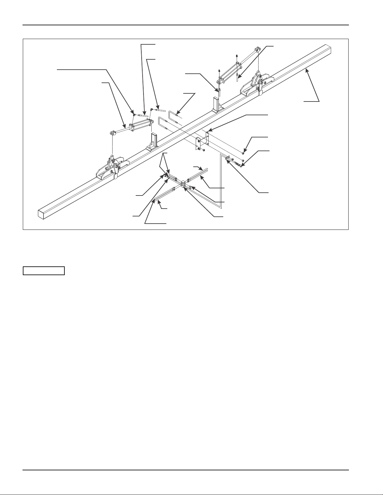
Wing Fold Plumbing Installation
See Figure 3-1 and Table 3-1 for parts names. When
assembly is done, tighten all fastening hardware to
the torques listed in Table 2-1 and Table 2-2. Tighten
u-bolts evenly to show an even amount of thread on
both legs of the u-bolt.
1. Assemble the base of each cylinder to a cylinder
base mount. Secure each with a clevis pin and the
hairpin clips that come with the cylinders. Be sure the
cylinders are set with the hose ports on the top when
installation is done.
2. Assemble the rod end of each cylinder to the top of
the inner hinge arms. Secure each with the clevis
pins and the hairpin clips given with the cylinders.
3. Install the hydraulic manifold mounting bracket on
the upper leg of the left-hand U-bolt on the center
tool frame (See Figure 3-1.)
4. Assemble the hydraulic manifold to the manifold
mounting bracket using bolts and nut s provided (See
Figure 3-1.)
5. Insert Hose B with a 90° fitting to the base end of the
left-hand cylinder. Insert the other end to the bottom
hole in the left-hand side of the hydraulic manifold.
3-2 F-140-0512 Edition
Figure 3-1: Hydraulic Installation
6. Insert Hose A with a 90° fitting to the rod end of the
left-hand cylinder. Insert the other end of the hose to
the top hole in the left-hand side of the hydraulic
manifold.
7. Insert Hose D with a 90° fitting to the base end of the
right-hand cylinder . Insert the other end to the bottom
hole in the right-hand side of the hydraulic manifold.
8. Insert Hose E with a 90° fitting to the rod end of the
right-hand cylinder. Insert the other end of the hose
to the top hole in the right-hand side of the hydraulic
manifold.
9. Insert coupling Hoses C (2 hoses supplied - 48" long
on all models, coupler fittings are owner supplied) to
the holes in the front of the hydraulic manifold.
Connect the coupler fittings to the tractor.
10. Lift the cultivator clear of the stands. Leave the
stands under the main frame bar to prevent
accidental lowering.
11. Cycle the wing fold through several cycles to
completely charge the hoses and cylinders with
hydraulic oil. The hydraulic system must be free of air
to keep movement of the wings in control during
folding or unfolding. Add oil as needed to the tractor
hydraulic system.
Page 13

2000 SERIES HYDRAULIC HOSE TABLE
HOSE
ITEM PART NUMBER
A 1-397-010299-14 24" 2008-30HCF-94
1-397-010299-15 48" 2006-36HCF-94, 2008-36HCF-94, 2008-40HCF-94
1-397-010299-06 56" 2010-30HCF-94, 2010-30HCFLG-94, 2012-30HCF-94
1-397-010299-12 84" 2010-36HCF-94, 2010-38HCF-94, 2012-36HCF-94, 2012-40HCF-94,
1-397-010299-19 90" 2012-38HCF-94
B 1-397-010299-15 48” 2008-30HCF-94
1-397-010299-13 74” 2008-40HCF-94
1-397-010299-18 68” 2006-36HCF-94, 2008-36HCF-94
1-397-010299-17 78” 2010-30HCF-94, 2010-30HCFLG-94, 2012-30HCF-94
1-397-010299-20 108” 2010-36HCF-94, 2010-38HCF-94, 2012-36HCF-94, 2012-40HCF-94,
1-397-010299-21 120” 2012-30HCF-94
C 1-397-010299-15 48” ALL FOLD MODELS
D 1-397-010299-01 36" 2008-30HCF-94
1-397-010299-02 60” 2006-36HCF-94, 2008-36HCF-94, 2008-40HCF-94
1-397-010299-18 68” 2010-30HCF-94, 2010-30HCFLG-94, 2012-30HCF-94
1-397-010299-22 98” 2010-36HCF-94, 2010-38HCF-94, 2012-36HCF-94, 2012-40HCF-94,
1-397-010299102 102” 2012-38HCF-94
E 1-397-010299-02 60” 2008-30HCF-94
1-397-010299-24 80” 2006-36HCF-94, 2008-36HCF-94
1-397-010299-19 90” 2010-30HCF-94, 2010-30HCFLG-94, 2012-30HCF-94
1-397-010299-21 120” 2010-36HCF-94, 2010-38HCF-94, 2012-36HCF-94, 2012-40HCF-94,
1-397-010299126 126” 2012-38HCF-94
LENGTH USED ON MODEL
2016-30HCF-94
2016-30HCF-94
2016-30HCF-94
2016-30HCF-94
ASSEMBLY INSTRUCTIONS
Table 3-1: Hydraulic Hose Installation for 2000 Series Row Crop Cultivator
3-3
Page 14
ASSEMBLY INSTRUCTIONS
IMPORT ANT
IMPORT ANT
SP AC ER TUB E
(END TOOL FRAMES ONLY)
1/2-13 HEX LOCK NUT
WEEDING DISC LOCK PIN
1/8 HAIR PIN
CLEVIS
PIN
OFFSET WEED
DISC ASSEMBL Y
DISC HILLER
BRACKET
TOOL FRAME
MOUNT
WEDGE CASTING
1/2-13 X 8-1/2 HEX
HEAD CAP SCREW
545ma014585 op
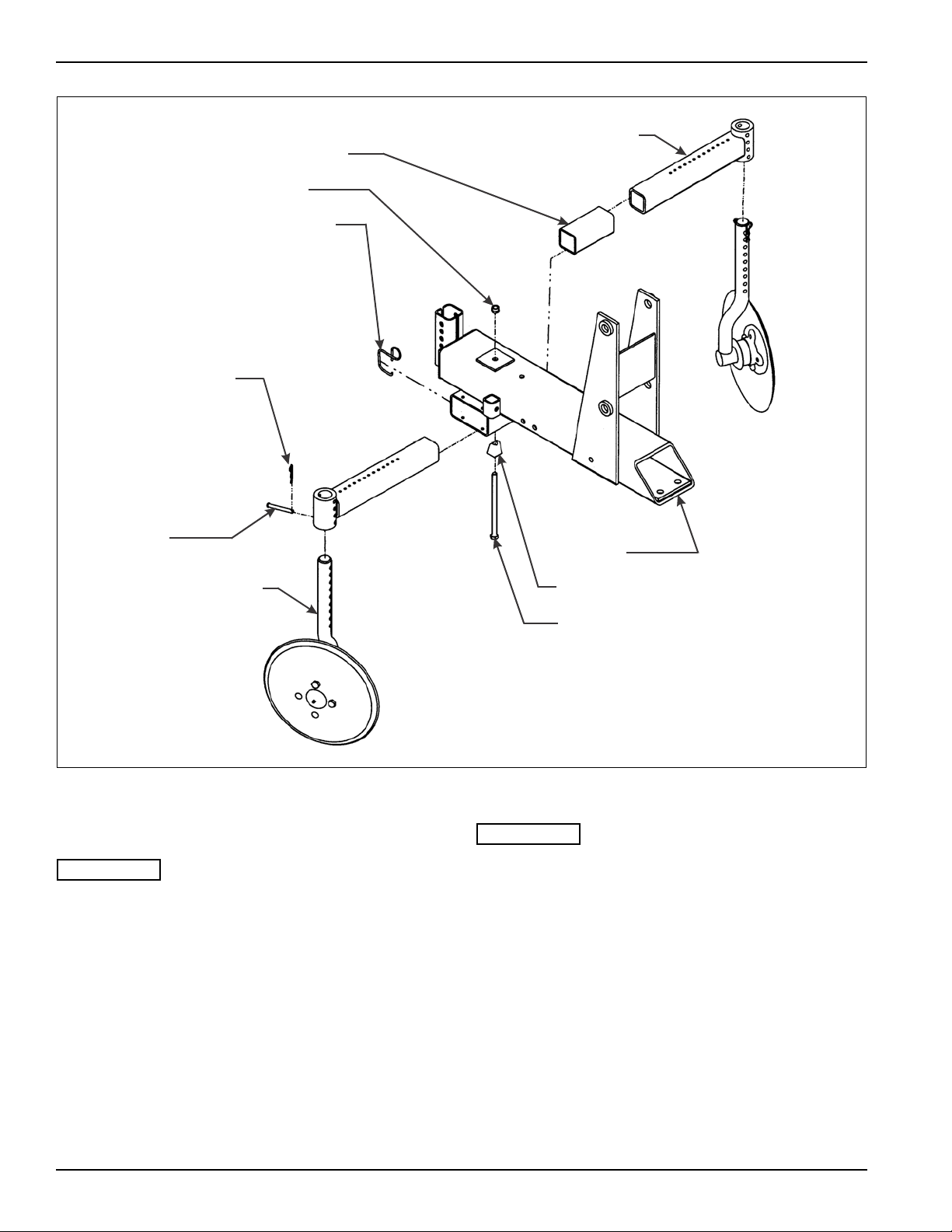
Figure 3-2: Disc Installation
Disc Installation
See Figure 3-2 for parts names. When assembly is
done, tighten all fastening hardware to the torques
listed in Table 2-1 and Table 2-2. Tighten u-bolts
evenly to show an even amount of thread on both
legs of the u-bolt.
The outer tool frames have a disc blade only on the
inside of the tool frame. The outside has a spacer
tube installed instead of the disc hiller bracket.
1. Remove the clevis pin and hair pin from each disc
hiller bracket.
2. Insert a disc blade and spindle assembly through
each disc hiller bracket to the desired depth.
Reinstall the clevis pin and hair pin.
3-4 F-140-0512 Edition
Page 15
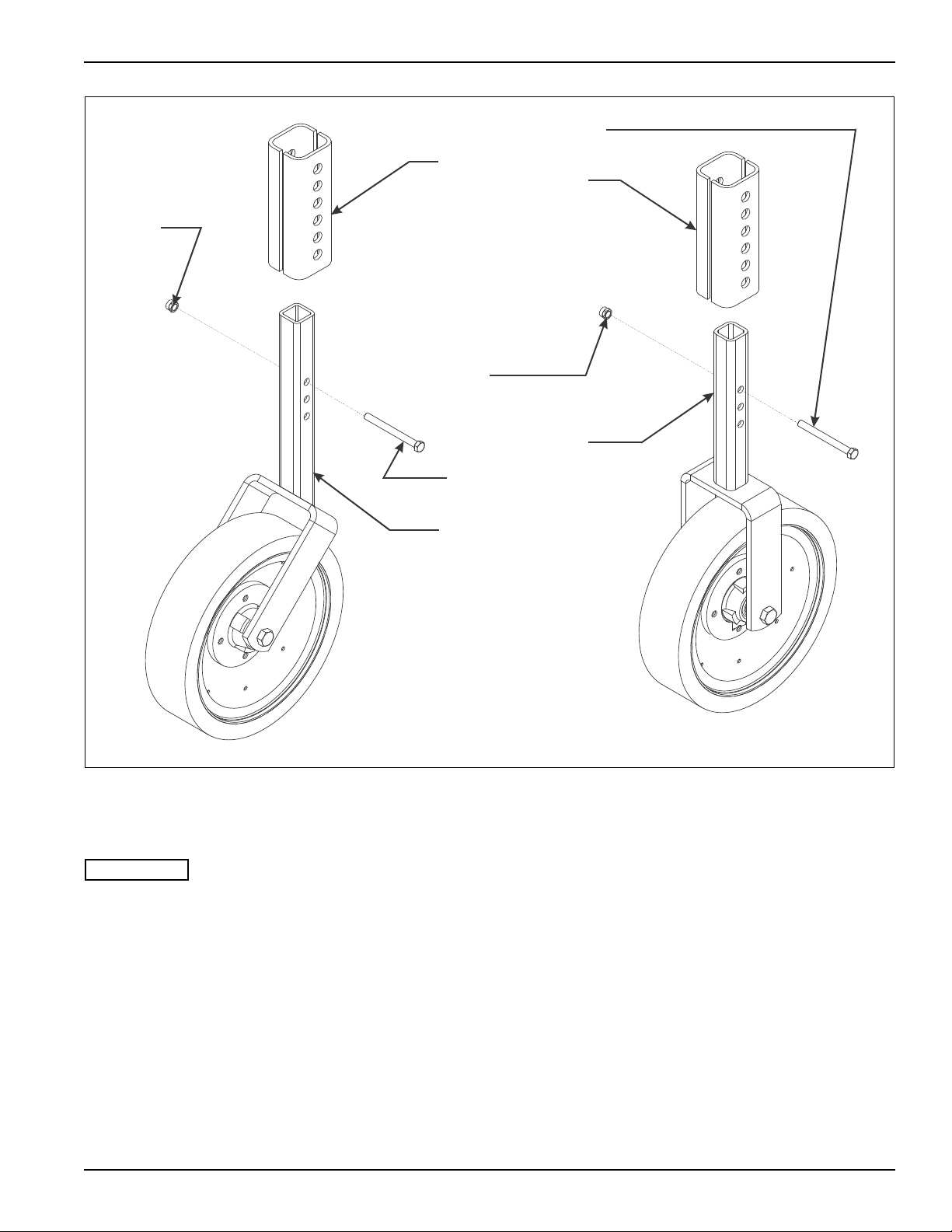
ASSEMBLY INSTRUCTIONS
IMPORT ANT
TOOL MOUNT
FRAME BRACKET
1/2-13 FLANGE
HEAD SERRATED
NUT
1/2-13 X 3-1/2 HEX
HEAD CAP SCREW
MIDDLE GAUGE
WHEEL ASSEMBL Y
(INNER FRAMES)
1/2-13 X 3-1/2 HEX
HEAD CAP SCREW
END GAUGE
WHEEL ASSEMBL Y
(OUTER FRAMES)
2000 gauge wheel assembly
1/2-13 FLANGE
HEAD SERRATED
NUT
Gauge Wheel Installation
See Figure 3-3 for parts names. When assembly is
done, tighten all fastening hardware to the torques
listed in Table 2-1 and Table 2-2. Tighten u-bolts
evenly to show an even amount of thread on both
legs of the u-bolt.
1. Find the end gauge wheel assemblies with the 45°
angle mounting forks.
2. Remove the 1/2-13 X 3-1/2 hex head cap screw and
serrated flange head nut from the gauge wheel
brackets. These are on the front of the outer tool
frames.
Figure 3-3: Gauge Wheel Installation
3. Slide a gauge wheel square tube up through the
bracket on each outer tool frame with the forks
pointing forward. Position the gauge wheel for proper
depth. Use the 1/2-13 X 3-1/2 hex head cap screw
and serrated flange head nut to position the gauge
wheel. Tighten the nut until wheel tube is securely
clamped into place.
4. The remaining middle gauge wheel assemblies are
installed on the inner tool frames. They are installed
using the steps described in steps 2 through 3.
3-5
Page 16
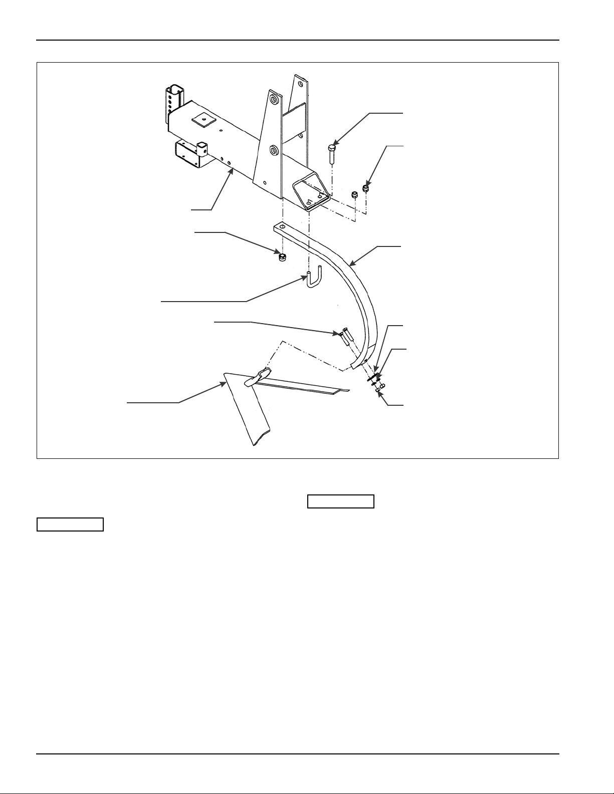
ASSEMBLY INSTRUCTIONS
IMPORT ANT
IMPORT ANT
3/4-10 X 3 HEX
HEAD CAP SCREW
5/8-11 HEX LOCK NUT
LONG SHANK
1/2 FLAT WASHER
1/2 SPLIT LOCK
WASHER
1/2-13 HEX NUT
TOOL MOUNT FRAME
3/4-10 HEX LOCK NUT
SHANK U-BOLT
1/2-13 X 2-1/2 PLOW BOLT
SWEEP
545m104598
Figure 3-4: Shank Installation
Shank Assembly
See Figure 3-4 for parts names. When assembly is
done, tighten all fastening hardware to the torques
listed in Table 2-1 and Table 2-2. Tighten u-bolts
evenly to show an even amount of thread on both
legs of the u-bolt.
1. Assemble the sweeps and half sweeps to the shanks
using 1/2-13 X 2-1/2 plow bolts, flat washer , split lock
washer, and nuts. Install spacer washers between
the shank and the sweep, as needed, to get desired
penetration angle.
If the optional shields are to be used, the shield
mounting brackets should now be installed (See
Section 4, “Operation and Maintenance” for
operation and maintenance procedures.)
2. Position the shank with the right-hand sweep (the
half sweep with the right-hand wing) under the rear of
the left end tool frame. Secure it with the shank u-bolt
and 5/8-11 hex lock nuts, and a 3/4-10 X 3 hex head
cap screw and hex lock nut.
3. Position the shank with the left-hand sweep (the half
sweep with the left-hand wing) under the rear of the
right most tool frame. Secure it with the shank u-bolt
and 5/8-11 hex lock nuts, and a 3/4-10 X 3 hex head
cap screw and hex lock nut.
4. Install the remainder of the shanks (with full sweeps)
on the inner tool frames the same way as the end
shanks described above.
3-6 F-140-0512 Edition
Page 17
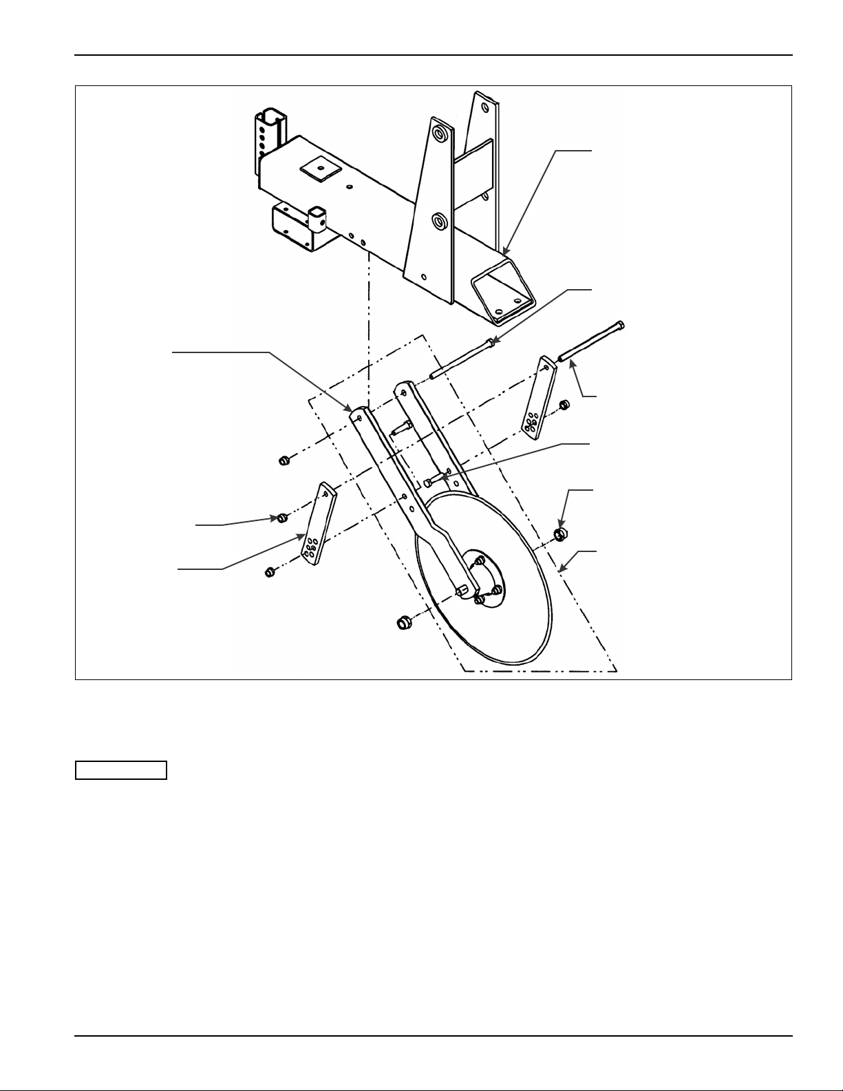
ASSEMBLY INSTRUCTIONS
IMPORT ANT
COULTER FORK
PLATE
1/2-13 HEX
LOCK NUT
COULTER
BRACE
TOOL MOUNT FRAME
1/2-13 X 8 HEX
HEAD CAP SCREW
1/2-13 X 8-1/2 HEX
HEAD CAP SCREW
1/2-13 X 2 HEX
HEAD CAP SCREW
3/4-10 HEX LOCK NUT
COULTER FORK
ASSEMBLY
545m104383 op
Figure 3-5: Coulter Blade Installation
Coulter Blade Installation
See Figure 3-5 for parts names. When assembly is
done, tighten all fastening hardware to the torques
listed in Table 2-1 and Table 2-2. Tighten u-bolts
evenly to show an even amount of thread on both
legs of the u-bolt.
1. Loosely assemble a coulter brace to the outer sides
of each coulter fork with 1/2-13 X 2 hex head cap
screws and hex lock nuts (Figure 3-5 shows proper
mounting position.)
2. Loosely assemble each coulter fork assembly to a
tool frame with a 1/2-13 X 8 hex head cap screw
inserted through the coulter fork side, the tool frame,
and the other coulter fork side, secured with a locking
nut (Figure 3-5 shows proper mounting position.)
3. Loosely attach the coulter braces to the tool frames
by inserting a 1/2-13 X 8-1/2 hex head cap screw
through one brace, the tool frame, and through the
other brace. Secure them with 1/2-13 hex lock nuts.
4. Leave all attaching hardware loose until final
adjustments are made (See “Initial Setup” on
page 4-3 for operation and maintenance
procedures.)
3-7
Page 18
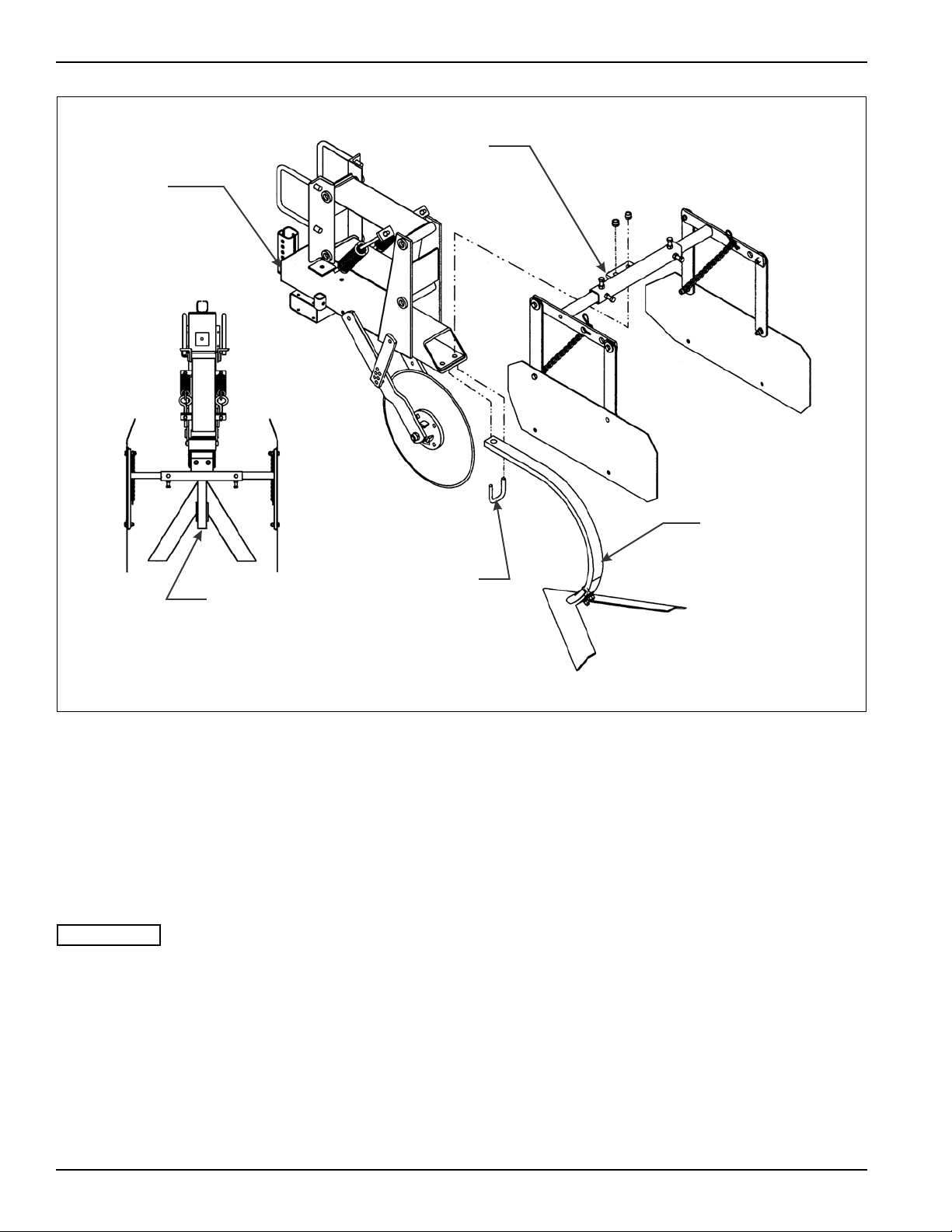
ASSEMBLY INSTRUCTIONS
IMPORT ANT
545m104649 op
FRAME TOOL
MOUNT
TOP VIEW
ASSEMBLED
SHANK
SHIELD MOUNTING
BRACKET
SHANK
U-BOLT
SHANK
Figure 3-6: Shield Installation (Option)
Shields
1. Mount the shield bracket centered over the shank
(See Figures 3-4 and 3-6) during shank installation.
(See “Shank Assembly” on page 3-6.)
2. Install the shank u-bolt over the shank, through the
frame tool mount and the shield mounting bracket.
Secure with 5/8-11 hex lock nuts.
The outer end tool frames only have a half shield,
found on the inside of the tool assembly.
3-8 F-140-0512 Edition
Page 19
ASSEMBLY INSTRUCTIONS
IMPORT ANT
SHANK
U-BOLT
U-BOLT
OFFSET DISC
ASSEMBLY
AMMONIA KNIFE
ASSEMBLY
IRRIGATION RIDGERS
(OPTION)
FERTILIZER A TT ACHMENT
5/16-18 HEX LOCK NUT
FERTILIZER TUBE
ASSEMBLY
PLASTIC TUBE END
5/8-11 HEX LOCK NUT
RIDGER ASSEMBL Y
545m104602
Figure 3-7: Opt io n al Ac cessories Installation
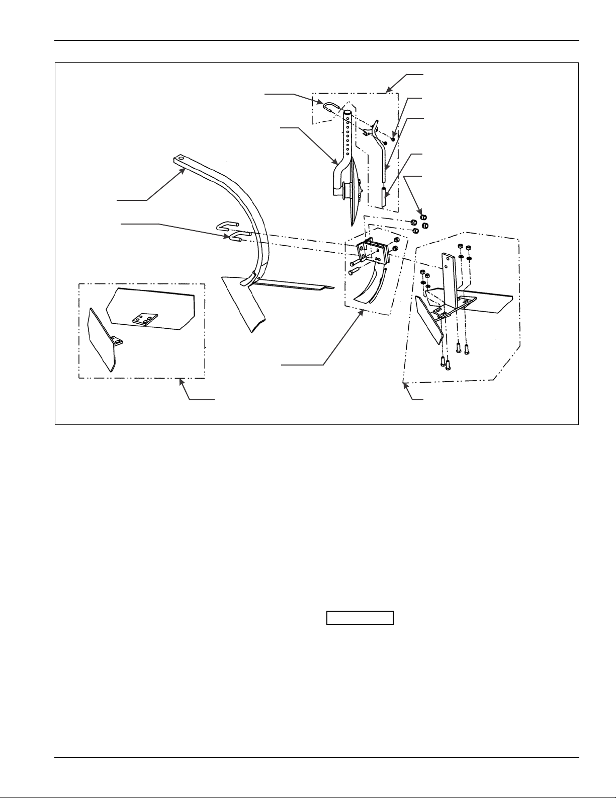
Ridgers
A ridger is an optional device that can be installed on
each shank.
1. Full ridgers should be installed on the inner shanks,
and half ridgers should be mounted on the outer, end
shanks. (Half ridgers should be inside of the tool
assembly.)
2. Assemble a shank clamp (See Figure 3-7) to the
rear of each shank. Secure the bracket with u-bolts
and 5/8-11 hex lock nuts.
Anhydrous Ammonia Knives
1. The ammonia knives are mounted in the same
Fertilizer Tubes
1. The fertilizer tubes should be mounted on the disc
Be sure to raise the tubes high enough to clear the
ground to prevent plugging the tubes.
manner as the ridgers. They cannot be used at the
same time the ridgers are being used (See
Figure 3-7.)
shaft assemblies. Secure with a u-bolt and 5/16-18
hex lock nuts (See Figure 3-7.)
3-9
Page 20
ASSEMBLY INSTRUCTIONS
WARNING
WARNING
5/8-11 X 3 HEX
HEAD CAP SCREW
5/8-11 SPLIT
LOCK WASHER
5/8-11 HEX NUT
LIFT ASSIST WHEEL
MAIN FRAME
MOUNTING
BRACKET
lift assist wheel op
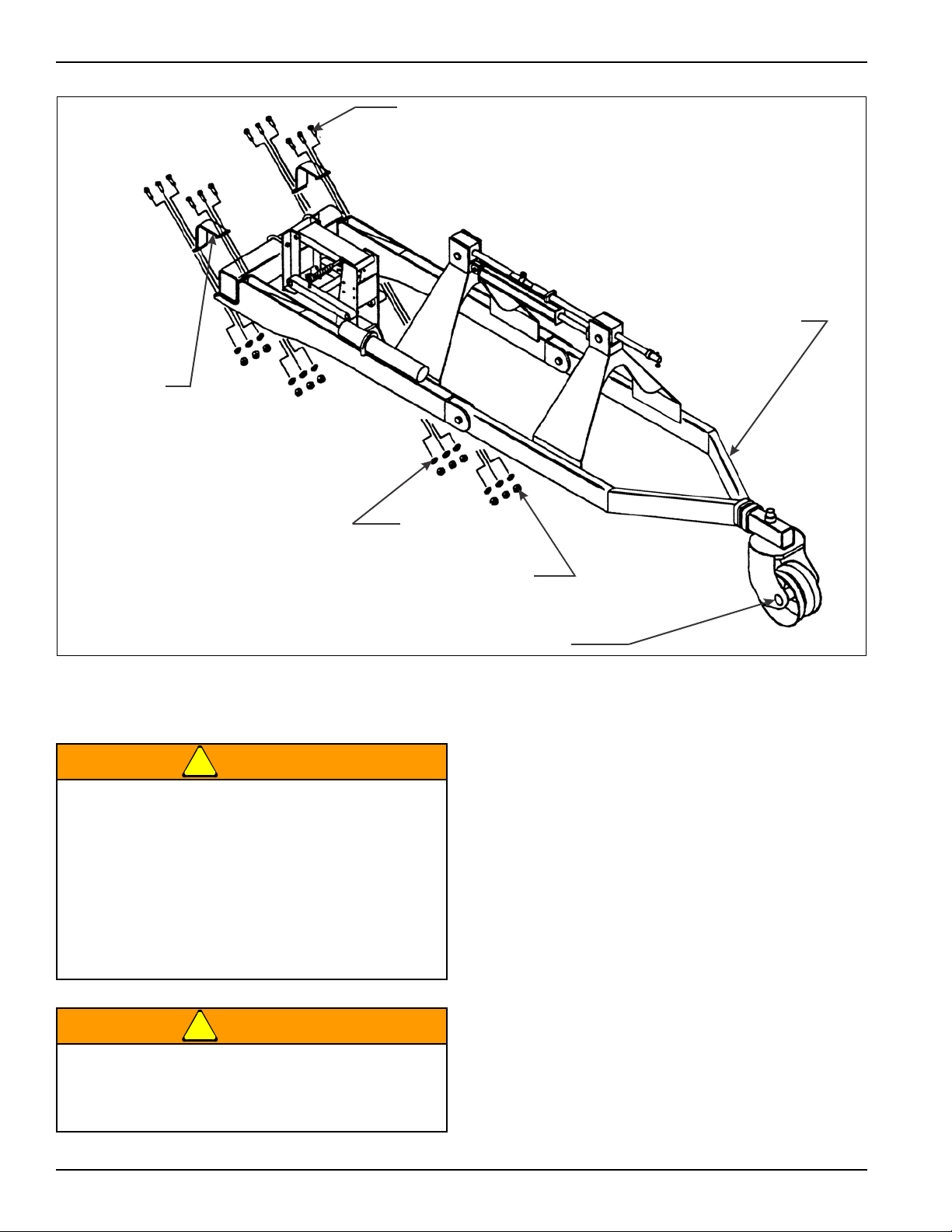
Lift Assist Wheel
An escaping hydraulic oil under pressure can
produce enough force to penetrate the skin,
causing serious personal injury. Before applying
pressure to the system, be sure all connections
are tight and that lines, pipes, and hoses are not
damaged before disconnecting lines, be sure to
relieve all pressure. Hydraulic oil escaping from a
very small hole can be almost invisible. Use a
piece of cardboard or wood, not your hands, to
search for suspected leaks.
If injured by escaping hydraulic oil, see a doctor
at once. Serious infection or reaction can develop
if proper medical treatment is not administered
immediately.
Figure 3-8: Lift Assist Wheel Installation
1. Place the base of the lift assist wheel frame against
the main frame bar, straddling (on both sides of) the
center tool frame assembly. Secure the assist wheel
using the mounting brackets, 5/8-11 X 3 hex head
cap screws, lock washers, and hex nuts that come
with the lift assist wheel (See Figure 3-8.)
2. Coupling hoses are to be owner-supplied. They
should be long enough to allow lifting or lowering of
the cultivator without stretching the hoses. Be sure to
set the hoses so not to interfere with the operation of
the cultivator. Once set, secure the hoses with tie
wraps.
3-10 F-140-0512 Edition
Page 21
ASSEMBLY INSTRUCTIONS
545m104650 op
PARALLEL LINKAGE
BOLT
FRAME TOOL MOUNT
1/4-28 HEX
LOCK NUT
SPRAY NOZZLE
MOUNT
ATTACH SPRAY NOZZLES
AND HOSES HERE
1/4-28 X 1 HEX
HEAD CAP SCREW
1-8 HEX NUT
1/2-13 X 1 HEX
HEAD CAP SCREW
1/2-13 HEX JAM NUT
SPRAY MOUNT
BRACKET
SPRAY NOZZLE
BAR
SPRAY NOZZLE
ARM MOUNT
1/4-20 X 1-1/2
HEX HEAD
CAP SCREW
ARM MOUNTING
BAR
1/4-20 HEX
LOCK NUT
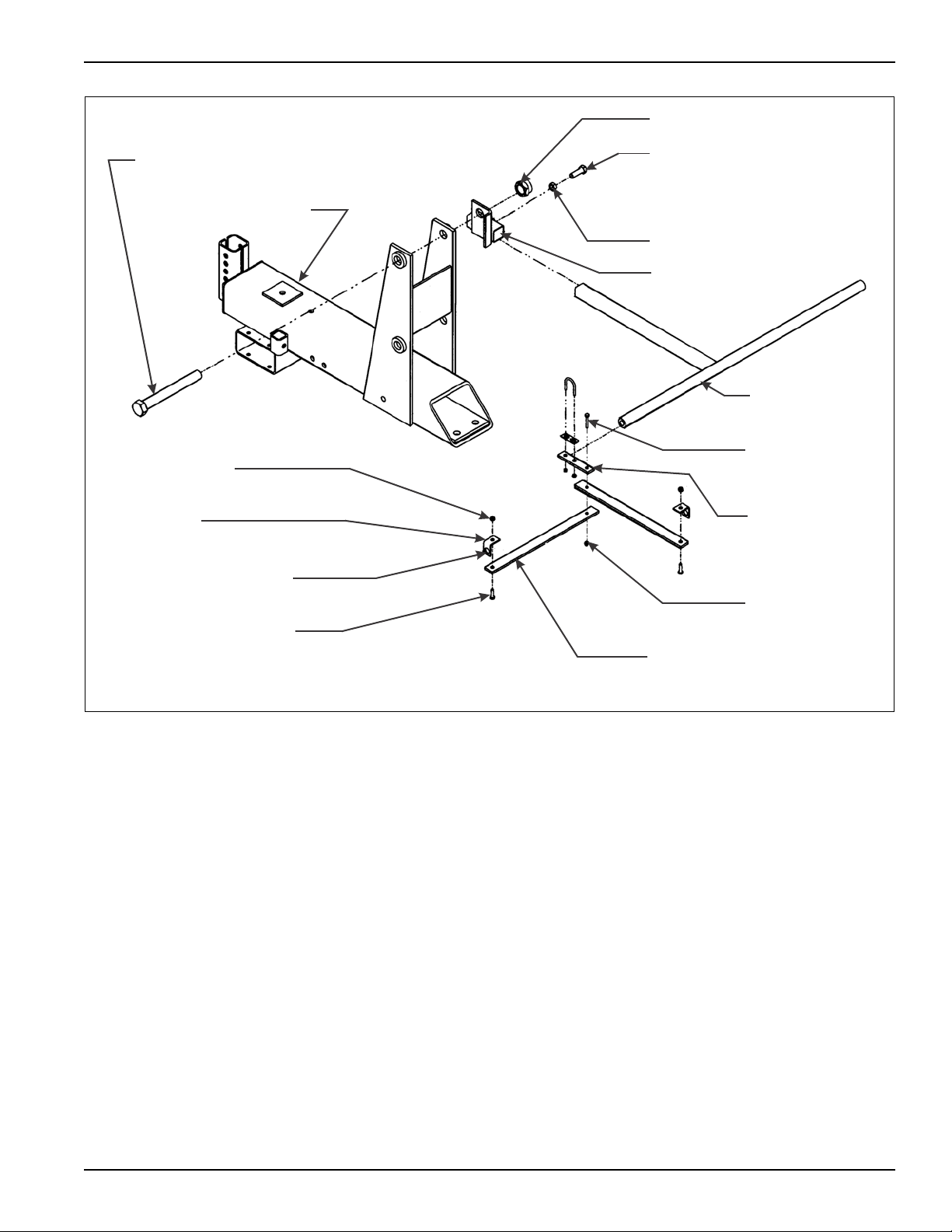
Figure 3-9: Spray Nozzle Mount Installation
Spray Nozzle Mount Attachment
The optional spray nozzle attachment adds a spray
accessory to the cultivator . One spr ay nozzle attachment
services two rows on the cultivator , so they should be
attached to every other tool frame (See Figure 3-9.)
1. Remove the 1-8 hex nut from the rear, top, parallel
linkage bolt. Install the spray mounting bracket to the
parallel linkage bolt and replace the nut. Tighten it
until the side plates are just snug against the bushing
of the top parallel linkage.
2. Assemble the spray nozzle arm mount to the spray
3. Assemble the spray nozzle bars to each other.
4. Assemble the remaining spray nozzle mounts to the
5. Assemble these spray nozzle arm assemblies to
mount bracket and secure it with the 1/2-13 X 1 hex
head cap screw and hex jam nut.
Assemble the arm mounting bar with a 1/4-20 X
1-1/2 hex head cap screw, a spray nozzle arm
mount, and hex lock nut. There should be two sets o f
these assemblies per attachment.
extended ends of the four spray nozzle bars with
1/4-28 X 1 hex head cap screws, and hex lock nuts.
each end of the spray nozzle arm mount using a
u-bolt, u-bolt bracket, and nut.
3-11
Page 22
ASSEMBLY INSTRUCTIONS
IMPORT ANT
5/8-1 1 T OOL MOUNT
U-BOLT
TOOL FRAME
BAR
TOOL FRAME
MOUNT
3/4-10 U-BOLT
5/8 FLAT WASHER
5/8-11 HEX LOCK NUT
HITCH FRAME
WELDMENT
3/4-10 HEX
LOCK NUT
HITCH ASSEMBL Y
HITCH WELDMENT
545m104766 op
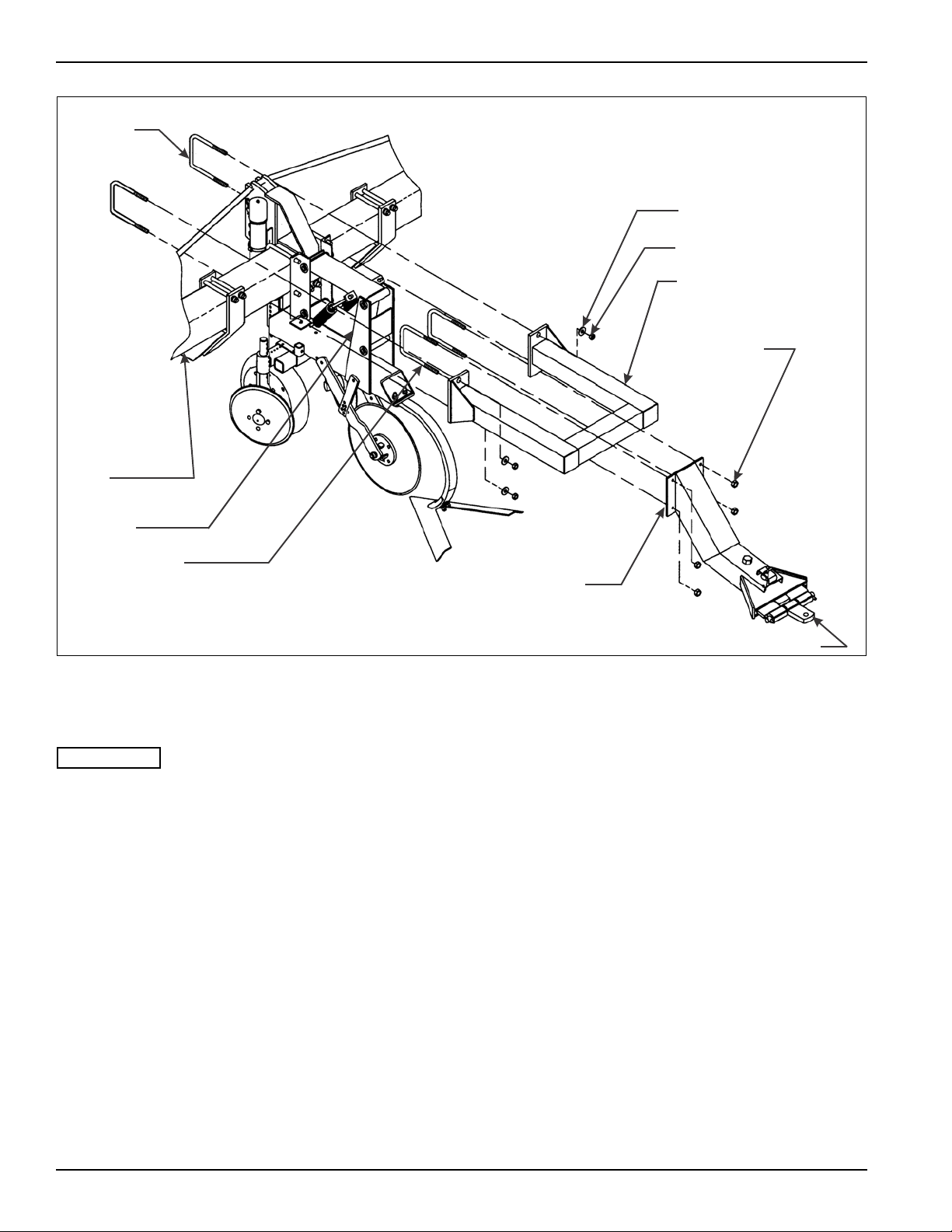
Nurse Tank Hitch Assembly
See Figure 3-10 for parts names.
1. Set tool frame bar on support stands.
2. Attach the hitch frame weldment to the tool frame bar
by straddling it around the center tool frame mount
assembly. Use the tool mount 5/8-11 u-bolts, flat
washers, and hex lock nuts to secure this assembly.
3. Assemble the hitch assembly to the hitch frame
weldment (See Figure 3-10.)
a. Align the hitch assembly centered on the hitch
frame weldment.
b. Use the 3/4-10 u-bolts and hex lock nuts to
secure these weldments.
Figure 3-10: Nurse Tank Hitch Installation
3-12 F-140-0512 Edition
Page 23
ASSEMBLY INSTRUCTIONS
1
23456
7
8
9
101211
2000B row crop decals
3
5
2
6
10
12
3
7
3
4
526
9
146
4
1
9
11
1
8
Figure 3-11: Decal Installation
3-13
Page 24

ASSEMBLY INSTRUCTIONS
Decal Placement
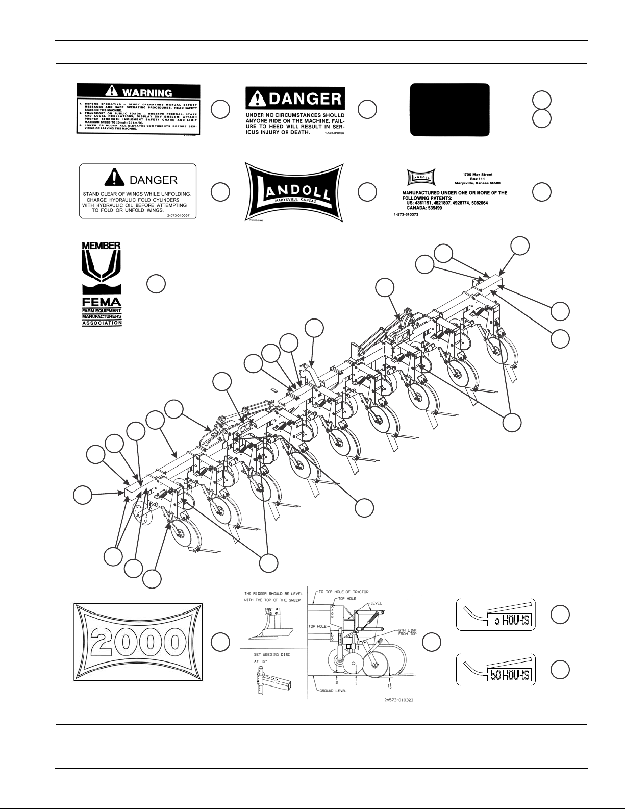
Decals are extremely important for naming purposes and
for alerting others to the presence of the machine.
PLACE ALL DECALS on the cultivator as shown in
Figure 3-1 1. Center them as ne ar ly as possible between
the top and bottom on the frame bar. Sometimes, shank
spacing may position a tool frame too near the end of the
frame bar to place a reflective tape square exactly as
shown. Then place the square between the U-bolt s on
the tool frame as near the proper location as possible. A
red reflective square is attached to the rear of the leftand right-hand end tool frames at the factory. If any
decals become unreadable, or are destroyed during use,
get replacement decals from your Landoll dealer as soon
as possible, and replace them on the machine.
3-14 F-140-0512 Edition
Page 25

Notes:
ASSEMBLY INSTRUCTIONS
3-15
Page 26

ASSEMBLY INSTRUCTIONS
3-16 F-140-0512 Edition
Page 27
Chapter 4
DANGER
DANGER
DANGER
DANGER
DANGER
CAUTION
Operation and Maintenance
Never allow anyone to ride on the 2000 Series
Row Crop Cultivator at any time. Allowing a
person to ride on the machine can inflict serious
personal injury or death to that person.
Coulter blades are extremely sharp. Exercise
extreme care when working on or near disc
blades. Do not allow discs to roll over or fall o nto
any bodily part. Do not allow wrenches to slip
when working near disc blades. Neve r pus h
wrenches toward disc blades. Do not climb over
machine above disc blades. Failure to stay clear
of disc blade edges can cause serious personal
injury or death.
All hydraulically elevated equipment must have
cylinder lockouts installed or be lowered to the
ground, when servicing or when equipment is
idle. Failure to take preventive measures against
accidental lowering can result in serious
personal injury.
Never stand under or near the hydraulic folding
wings during folding or unfolding operations. The
wings may drop very quickly resulting in serious
injury or death to anyone under or near the
cultivator wings.
When transporting the unit, place cylinder
lockouts in the transport lock position after fully
extending the cylinders. Insert the lockout pins to
secure the cylinder lockouts. Failure to lockout
the cylinders can cause the unit to settle during
transport, which can result in serious injury or
death and cause damage to the equipment.
When transporting farm implements on public
roads, it is the responsibility of the operator to
abide by state and local laws concerning wide
loads, speed, safety emblems and safety lighting
equipment. Drive at safe speeds. Particularly
when rounding corners, crossing rough ground
or driving on hillsides, to prevent tipping the
tractor.
4-1
Page 28
OPERATION AND MAINTENANCE
545-105939
32-1/2
CATEGORY II WITHOUT
QUICK HITCH
38
CATEGORY III WITH AND
WITHOUT QUICK HITCH
32-1/2
CATEGORY II WITH
QUICK HITCH
Tractor Preparation
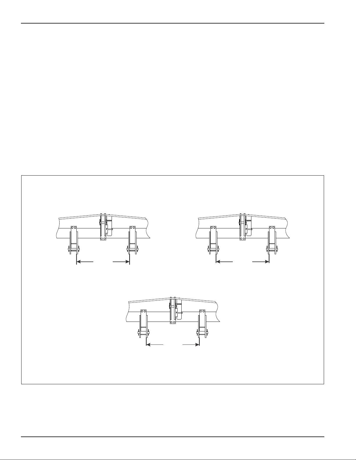
The 2000 Series Row Crop Cultivator may be used on
tractors equipped with category II or III three-point
hitches with quick couplers. Before attaching the
cultivator, prepare the tractor as follows:
The rear tractor tires should be inflated equally and
ballast added according to the tractor operator’s manual.
1. Install front-end weights as needed on tractor to
maintain stability (See Section 2, “Standard
Specifications” for cultivator weight). Lower the
draft arms, by means of the draft arm control lever
until the draft arm hitch sockets align with the lower
hitch brackets on the cultivator. Place the draft arm
control lever in the least sensitive position. Remove
stabilizer bars or sway blocks during hookup and
operation. Replace after hookup for transporting.
Cultivator Preparation
1. Before operating the cultivator, inspect it to be sure it
is in good operating condition.
2. Replace badly worn or missing parts and any rough
or worn wheel or disc bearings.
3. While the machine is new, bolt tightness should be
checked after a few hours of operation. Tighten any
loose nuts or bolts.
Attaching To Three Point Hitch
1. Carefully back the tractor into place.
2. Attach the cultivator to the tractor draf t arms. Be sure
the hitch pins and sleeves are installed as shown in
Figure 4-1.
3. Reinstall the stabilizer bars or sway blocks before
transporting.
4-2 F-140-0512 Edition
Figure 4-1: Examples of Hitch Setups
Page 29
OPERATION AND MAINTENANCE
THE RIDGER SHOULD BE LEVEL
WITH THE TOP OF THE SWEEP
SET WEEDING DISC
AT 15º
TO TOP HOLE OF TRACTOR
TOP HOLE
LEVEL
TOP
HOLE
GROUND LEVEL
6TH LINK
FROM TOP
1-1/2”
1”2”
2m573-010323
Figure 4-2: Recommended Settings for Initial Setup
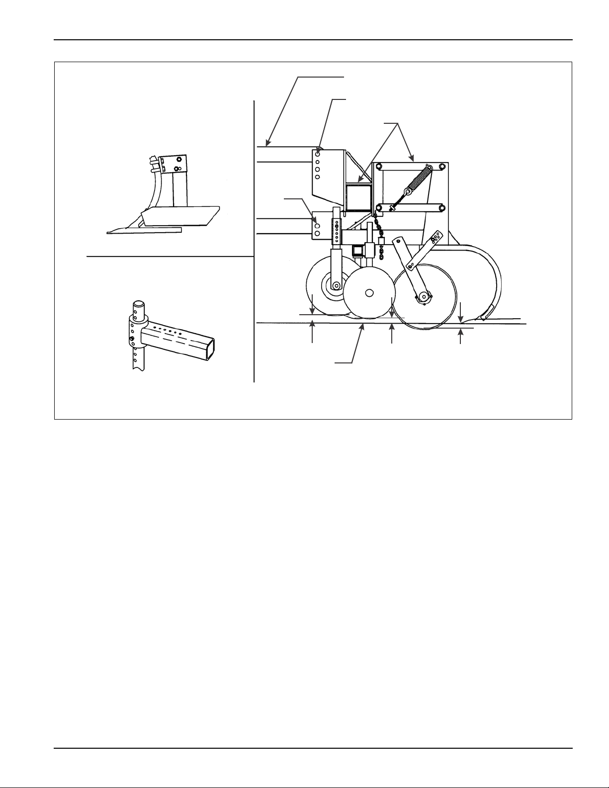
Initial Setup
1. Set the tractor and cultivator on a cement or other
hard, level surface, and check that the top
adjustment link is greased and easy to operate.
2. Lower the cultivator until the swee ps contact the
surface. The gauge wheels should now be ab out two
inches above the surface and the tool frames should
be level with the surface. If not, adjust the top
adjusting link until the tool frames are level, and set
the gauge wheel adjustment (See Figure 3-3) to two
inches above the surface.
3. Raise the cultivator just off the surface. Check for
side to side levelness of the main frame bar with the
tractor rear axle. If necessary, level the frame bar
with the tractor’s draft arm vertical height adjuster.
4. Adjust weeding discs to 1" above swee p at a 15°
angle (See Figure 4-2.)
5. Adjust coulter to 1-1/2” below the sweep.
6. Adjustments for particular field conditions are
described in the following section.
4-3
Page 30

OPERATION AND MAINTENANCE
WARNING
WARNING
Field Operation
1. Remove the stabilizer bars or sway blocks from the
drawbar assembly on the tractor.
2. Pull the cultivator a few feet at the approximate
desired depth and speed you intend to maintain
during use. Adjust the cultivator properly according to
the procedures described in “Gauge Wheel
Adjustment” on page 4-5, “Coulter Adjustment”
on page 4-5, “Disc Adjustment” on page 4-7,
“Disc Bearing Maintenance” on page 4-7, “Tool
Frame” on page 4-8, “Ridgers and Knives” on
page 4-8, “Shields” on page 4-9, and “Lift Assist
Wheel” on page 4-9.
3. Always lift the cultivator completely out of the
ground before turning or backing to prevent
shank, disk, or coulter damage, or damage to their
respective mounting brackets.
4. Reduce speed at field ends, raise the cultivator out
of the ground, and if needed, assist turning by using
the wheel brakes. Do not lower the cultivator into the
ground during turning operations.
5. After a few hours of operation, check all bolts for
tightness. Tighten any loose bolts.
6. When folding wings on wing fold models always
be sure that the wings are out of the ground
before folding. When unfolding the wings, leave
the hydraulic lever in the “EXTEND” position for
a few seconds to lock the wings in operational
position.
7. READ WARNINGS ON THIS PAGE.
8. The Nitrogen accumulator (See Figure 4-9) on the
Lift Wheel Assist provides protection for the hitch
mast and tractor three-point top link, when fully
mounted. It also serves as a cushion to shock loads
when the raised implement is maneuvered. Oil is
transferred from the cylinder to the Nitrogen
accumulator while moving over uneven ground to
relieve excess stress. After moving back to level
ground, pressure build-up within the accumulator
forces oil back into the cylinder. This provides lift
assist, which is preset by the adjustment screw. See
“Lift Assist Wheel” on pa ge 4-9 BEFORE adjusting
this screw.
An escaping hydraulic oil under pressure can
produce enough force to penetrate the skin,
causing serious personal injury. Before applying
pressure to the system, be sure all connections
are tight and that lines, pipes, and hoses are not
damaged. Before disconnecting lines, be sure to
relieve all pressure. Hydraulic oil escaping from a
very small hole can be almost invisible. Use a
piece of cardboard or wood, not your hands, to
search for suspected leaks.
If injured by escaping hydraulic oil, see a doctor
at once. Serious infection or reaction can develop
if proper medical treatment is not administered
immediately.
To avoid personal injury, stay clear of lift assist
wheel and implement during operation. Perform
any adjustments or service on implement when it
is in lowered position.
4-4 F-140-0512 Edition
Page 31
OPERATION AND MAINTENANCE
IMPORT ANT
TOOL MOUNT
FRAME BRACKET
1/2-13 FLANGE
HEAD SERRATED
NUT
1/2-13 X 3-1/2 HEX
HEAD CAP SCREW
gauge wheel adjust
1/2-13 HEX LOCK NUT
TOOL MOUNT FRAME
1/2-13 X 8-1/2 HEX
HEAD CAP
SCREW
1/2-13 X 2 HEX
HEAD CAP SCREW
COUL TER BRACE
COUL TER FORK
2mb798-010108 op
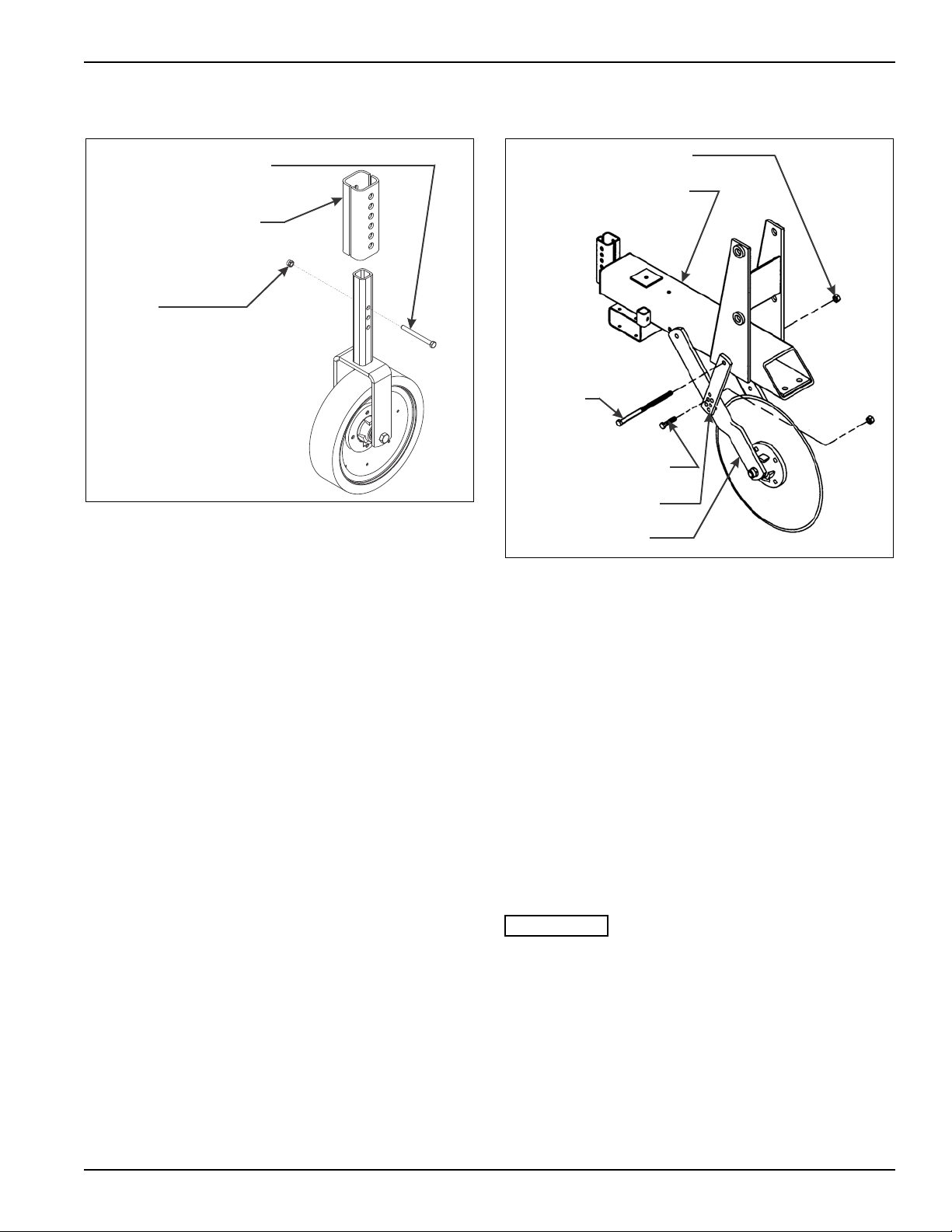
Gauge Wheel Adjustment
Figure 4-3: Gauge Wheel Adjustment
1. For stability, the gauge wheels must always apply
slight pressure against the soil. Adjust the gauge
wheels by raising or lowering, as needed, to reach
proper depth. To reach proper depth (See Figure
4-3):
a. remove the screw in the gauge wheel shaft
b. make the proper adjustment
c. reinstall the screw
d. tighten the screw and lock nut until the gauge
wheel is securely clamped into position.
2. There are several points to consider when setting the
gauge wheel depth:
a. When the cultivator is in the ground and the
depth is set, the tool frames should tip slightly
forward. This is done by raising or lowering the
gauge wheels and adjusting the tractor top
adjustment link.
b. On very soft or loamy soil, it may be necessary to
set the gauge wheels directly behind the tractor
tires a little different than the others. This allows
their respective sweeps to maintain the same
depth as the other sweeps.
c. The depth should be sufficient to move the
desired amount of soil and to get the sweep into
good, solid soil during high trash situations.
Coulter Adjustment
Figure 4-4: Coulter Adjustment
Initial setting for a coulter is at least one inch below the
working depth of the sweeps. Generally, the harder the
soil, the less pressure used on the coulters. To adjust
coulters (See Figure 4-4):
1. Remove the 1/2-13 X 8-1/2 hex head cap screw that
goes through the coulter brace and the to ol fra m e
mount.
2. Raise or lower the entire coulter fork asse mb ly un til
the proper height is reached. Use the lower two holes
in the coulter brace for 18" coulters (standard). Use
the next two holes (above) for the 20" inch coulter
option (See Figure 3-5.)
3. Reinstall the 1/2-13 X 8-1/2 hex head cap screw and
the hex lock nut through the coulter braces and tool
frame mount. Extra holes are also provided on the
lower coulter braces for more adjustment.
The coulters directly behind the tractor tires may
need to be set slightly different than the other
coulters.
4-5
Page 32
OPERATION AND MAINTENANCE
DISC HILLER BRACKET
SP ACER TUBE (END
TOOLS ONLY)
1/2-13 HEX LOCK NUT
WEEDING DISC LOCK
PIN
1/8 HAIR PIN
CLEVIS PIN
COTTER PIN
4 BOLT HUB
SPINDLE WASHER
HEX SLOTTED
NUT
1/4-28 HEX
JAM NUT
DUST CAP
GREASE ZERK
1/2-20 X 1
HEX HEAD
CAP SCREW
INNER CONE
BEARING CUP
INNER BEARING
CONE
OFFSET SPINDLE
WELDMENT
DISC
BLADE
TOOL FRAME
MOUNT
WEDGE CASTING
1/2-13 X 8-1/2 HEX
HEAD CAP SCREW
OFFSET WEED DISC
ASSEMBLY
545m104585
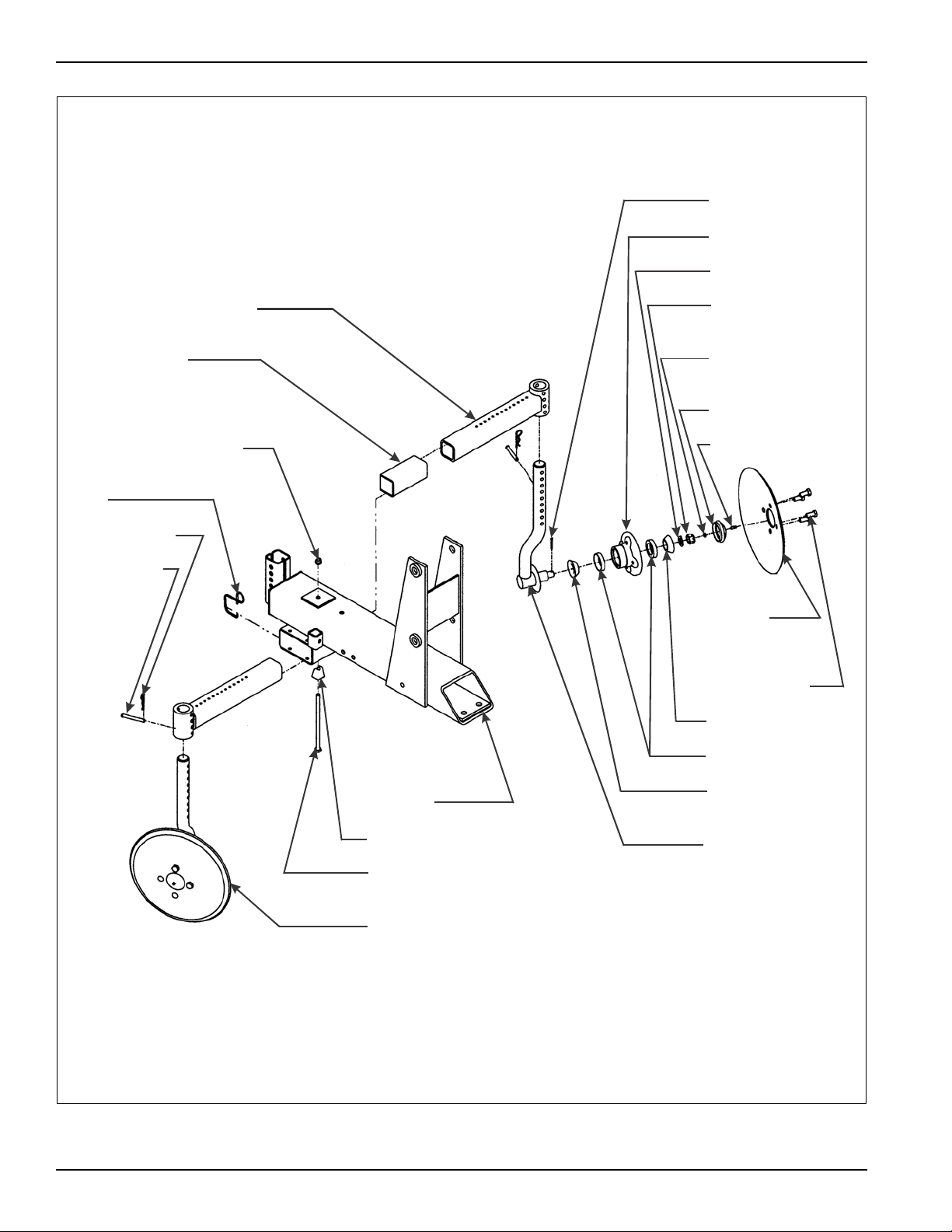
Figure 4-5: Disc Adjustment
4-6 F-140-0512 Edition
Page 33

OPERATION AND MAINTENANCE
IMPORT ANT
Disc Adjustment
Adjust the disc to the proper depth and pitch to create the
desired weeding effect. Discs working at different
settings from each other tend to make the machine fight
itself. Also, discs working too deeply into the soil tend to
throw up excess dirt, resulting in root pruning, which
causes the sweeps to plug. To adjust the discs (See
Figure 4-5):
1. DEPTH - Remove the 1/8 hair pin and clevis pin from
the offset weed disc spindle weldment, and set the
disc assembly to the desired depth. Standard depth
for optimum weeding is 1" to 1-1/2” below the
surface. Reinstall the clevis and hair pins.
2. WIDTH - Loosen the wedge casting in the bottom of
the tool frame. Remove the weeding disc lock pins
from the tool frames and disc brackets. Move the disc
assembly in or out as needed, replace the weeding
disc lock pins, and retighten the wedge casting.
Hammer upward on the head of the 1/2-13 X 8-1/2
hex head cap screw to set the wedge tightly and
replace hex lock nut.
Retighten the wedge casting cap screw several t imes
during the first hour of the machines operation.
3. ANGLE - Remove the clevis and hair pins from the
disc hiller brackets. Adjust the right and left disc
assembly to the same angle. Four angle settings are
allowed at: 11°, 15°, 19°, and 23° (15° nominal).
Replace the pins.
Disc Bearing Maintenance
Check all roller bearings occasionally for excess end
play. To adjust or replace the roller bearings:
1. Place the cultivator frame on blocks or stands just
high enough to lift the tire clear off the ground and
stable enough to prevent tipping.
2. Remove the disc/hub assembly (See Figure 4-5.)
3. Clean and inspect the bearings and hub cavity.
Replace any worn or defective parts.
4. Repack the roller bearings using a high quality
grease.
5. Reassemble the hub assembly, bearing, and seal.
6. Tighten the bearings while rotating the hub until ther e
is a slight resistance to hub rotation. Then, back the
nut off one notch until the hub rotates freely without
end play.
7. Install a new cotter pin and the dust cap.
8. Fill the hub cavity through the grease zerk with
high-quality grease until the grease is forced past the
seal. This will not damage the seal.
9. Wheel bearing maintenance should be done at the
start of every season, and more often when used in
extremely wet soil conditions.
4-7
Page 34
OPERATION AND MAINTENANCE
IMPORT ANT
3/4-10 U-BOLT
LIMIT CHAIN
7/16-14 HEX
LOCK NUT
7/16-14 X 2 HEX
HEAD CAP SCREW
2ma410-010905
545ma104602 op
SHANK
U-BOLT
SHANK
ANHYDROUS AMMONIA
KNIFE (OPTION)
LEFT HAND SIDE
5/8-11 HEX
LOCK NUT
RIDGER (OPTION)
RIGHT HAND
SIDE
Tool Frame
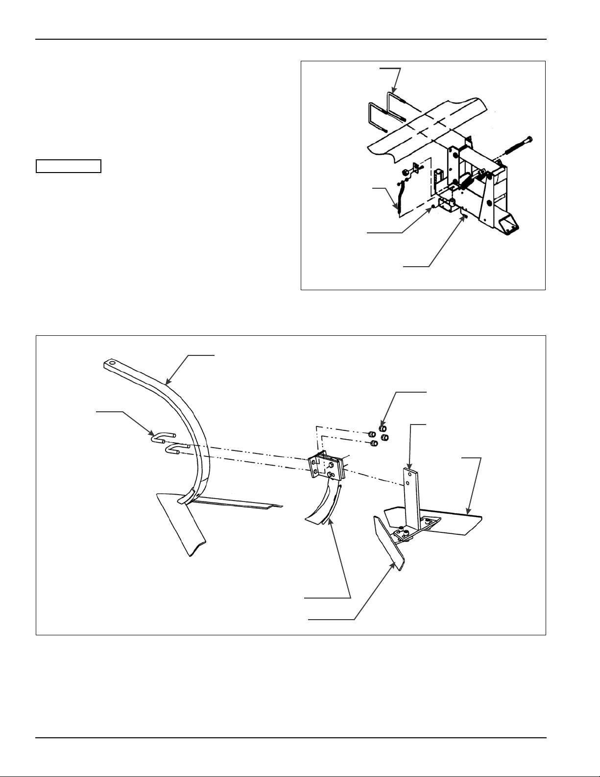
1. The length of up and down movement for the tool
frame is controlled by the limit chain (See Figure
4-6) on the left side of the tool frame. If a different
distance of movement is required, change the limit
chain one link at a time until the desired amount of
movement is met.
A longer limit chain setting will result in less ground
clearance when the machine is lifted out of the
ground.
Ridgers and Knives
1. Adjust the ridgers or anhydrous ammonia knives
(See Figure 4-7) by loosening the clamp bracket on
the shank, and slide the ridger or knife to th e desire d
depth. Loosen the ridger bracket bolts and slide the
ridgers in or out to the desired width. Retighten the
bracket bolts.
Figure 4-6: Limit Chain Adjustment
4-8 F-140-0512 Edition
Figure 4-7: Ridger and Knife Adjustment
Page 35
Shields
WIDTH ADJUSTMENT
SCREW
SHIELD ADJUSTMENT
CHAIN
liftadj op
ADJUSTMENT SCREW
NITROGEN
ACCUMULATOR
HYDRAULIC CYLINDER
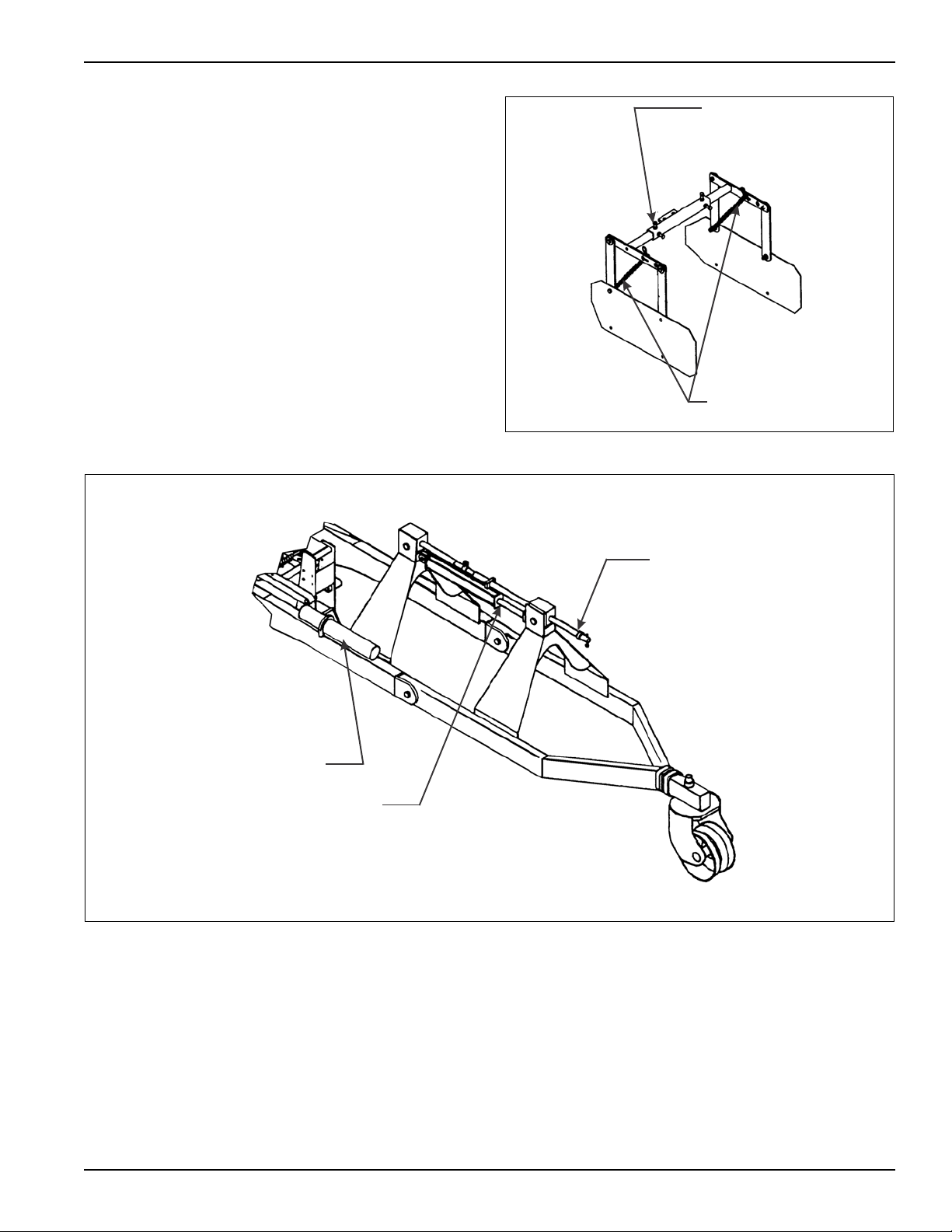
Adjust the shields by moving the shield adjustment chain
up or down one link at a time until the desired height is
reached (See Figure 4-8.) The sh ie ld width can be
adjusted by loosening the adjustment screws and sliding
the shields in or out to the desired width. Tighten the
adjustment screws.
Lift Assist Wheel
Adjust the optional lift assist wheel so that when the
machine is in use, the lift assist wheel is lifted clear of the
ground. Raise or lower the lift assist wheel, as needed,
with the adjustment screw on top of the lift assist wheel
frame (See Figure 4-9.)
OPERATION AND MAINTENANCE
Figure 4-8: Shield Adjustment
Figure 4-9: Lift Assist Wheel Adjustment
4-9
Page 36
OPERATION AND MAINTENANCE
HINGE POINTS
(50 HOURS)
COUL TER ASSEMBLY
BEARINGS (5 HOURS)
DISC ASSEMBL Y
BEARINGS
(5 HOURS)
2000b row crop lube
Tool Hold Down Springs
The hold down springs are on either side of the pa rallel
linkage on the tool frames and are factory adjusted for
most normal conditions. Tighte ning the springs increases
the ground tool pressure. Too much pressure will shorten
the life of the ground tools.
Hydraulic Maintenance
1. Check the tractor hydraulic fluid level per tractor
owners manual and after any leakage. Check fluid
level with the cylinders in the retracted position.
2. If a cylinder leaks, disassemble the parts to
determine the cause of the leak. Any time a cylinder
is opened up, or whenever any seal replacement is
necessary, it is advisable to clean all parts and
replace all seals Seal kits are available from your
Landoll dealer.
3. Check all hydraulic hoses weekly , Look for bind ing or
cracking. Replace all worn or defective parts
immediately.
Lubrication
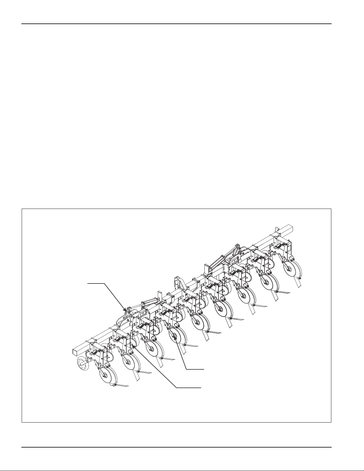
See Figure 4-10 for lubrications points and
recommended maintenance schedule.
1. The coulter hub bearings, and disc hiller bearings
should be lubricated with a high grade multi-purpose
grease twice a day or every five hours. They should
be filled till the grease is forced past the seals. This
will not damage the seals.
2. The wing fold pins (if applicable) should be greased
daily with a high grade multi-purpose grease.
4-10 F-140-0512 Edition
Figure 4-10: Lubrication Schedule
Page 37

Storage
The service life of the cultivator will be extended by the
following proper off-season storage practices:
1. Completely clean the unit and inspect the machine
for worn or defective parts. Replace defective and
worn parts, as needed, to avoid delays the following
season.
2. Repaint all areas where the original paint film is worn
off.
3. Grease all exposed metal surfaces of shanks, points,
and coulters.
4. Lubricate as suggested in “Lubrication” on
page 4-10.
5. Store the unit in a shed, or under a tarpaulin, to
protect it from the weather. The ground tools and
tires should rest on a board or other device to keep
them out of the soil.
6. Fully extend the hydraulic gauge wheel cylinders,
and place the cylinder lockouts in the transport lock
position over the cylinder rods. Secure the lockouts
with the lockout pins.
7. Always place the swivel jack on the interior mount
before setting the machine in motion.
OPERATION AND MAINTENANCE
4-11
Page 38

OPERATION AND MAINTENANCE
4-12 F-140-0512 Edition
Page 39

The Troubleshooting Guide, shown below, is included to
help you quickly locate problems that can happen using
your 2000 Series Row Crop Cultivator. Follow all safety
precautions stated in the previous sections when makin g
any adjustments to your machine.
PROBLEM PROBABLE CAUSE SOLUTION
Chapter 5
Troubleshooting Guide
SWEEPS NOT PENETRATING THE SOIL Tool bar, parallel linkage, and sweeps are
not set properly.
Severe conditions Add washers on top bolt between sweep
Gauge wheels are not set properly. Gauge wheels must be set approximately
The weeding discs are holding the sweep
out of the ground.
Coulter not set properly. Raise the coulter (See “Coulter
The ridgers are on upside-down Reassemble ridgers properly (See
WEEDING DISCS ARE PRUNING
CROPS
GAUGE WHEELS ARE NOT
CONTACTING THE SURFACE
SLABBING Weeding discs not set properly. Adjust the weeding discs to break up the
TRASH CATCHING ON COULTER
BLADE
Crops are too big Remove weeding discs (See “Disc
Weeding discs are set at too great an
angle
The gauge wheel adjustment is not set
correctly
Coulter not set properly. Raise the coulter (See “Coulter
The weeding discs are holding the sweep
out of the ground.
The top link is too long, causing the swe ep
to ride on its heels.
Coulter is set to run too deep. Raise the coulter. Run it shallower (See
Weeding disc is throwing too much dirt
and trash.
Adjust top link in 1/2 turn increments until
tool bar, parallel linkage, and sweeps
are running level in working depth (See
“Initial Setup” on page 4-3.)
and shank (See “Disc Installation” on
page 3-4.)
2" above sweep (See “Gauge Wheel
Adjustment” on page 4-5.)
Set the weeding discs approximately 1"
above the sweeps.
Adjustment” on page 4-5.)
“Ridgers and Knives” on page 4-8.)
Adjustment” on page 4-7.)
Reduce the angle.
Adjust gauge wheels properly (See
“Gauge Wheel Adjustment” on
page 4-5.)
Adjustment” on page 4-5.)
Set the weeding discs approximately 1"
above the sweeps.
soil in front of the sweep (See “Disc
Adjustment” on page 4-7.)
“Coulter Adjustment” on page 4-5.)
Reduce angle and/or run it shallower.
5-1
Page 40

TROUBLESHOOTING GUIDE
Notes:
5-2 F-140-0512 Edition
Page 41

Page 42

Equipment from Landoll Corporation is built to exacting
standards ensured by ISO 9001:2008 registration at all
Landoll manufacturing facilities.
Model 2000 Series
Row Crop Cultivator
Operator’s Manual
Re-Order Part Number F-140-0512
LANDOLL CORPORATION
1900 North Street
Marysville, Kansas 66508
(785) 562-5381
800-428-5655 ~ WWW.LANDOLL.COM
Copyright 2010. Landoll Corporation
"All rights reserved, including the right to reproduce this material or portions thereof in any form"
F-140-0512 05/12
 Loading...