


ICE BEVERAGE DISPENSERS, IBD 25 SERIES 4500
Operation Manual
PN: 28-0417/02
|
Lancer Corp. |
|
6655 Lancer Blvd. |
|
San Antonio, Texas 78219 |
|
800-729-1500 |
|
Technical Support/Warranty: 800-729-1550 |
|
custserv@lancercorp.com |
|
lancercorp.com |
|
Manual PN: 28-0417/02 |
|
FEB 2006 |
Model Number |
FOR QUALIFIED INSTALLER ONLY |
“Lancer” is the registered trademark of Lancer © 2013 by Lancer, all rights reserved.

ABOUT THIS MANUAL
This booklet is an integral and essential part of the product and should be handed over to the operator after the installation and preserved for any further consultation that may be necessary. Please read carefully the guidelines and warnings contained herein as they are intended to provide the user with essential information for the continued safe use and maintenance of the product. In addition, it provides GUIDANCE ONLY to the user on the correct services and site location of the unit.
The installation and relocation, if necessary, of this product must be carried out by qualified personnel with up-to-date safety and hygiene knowledge and practical experience, in accordance with current regulations.
|
TABLE OF CONTENTS |
|
SPECIFICATIONS............................................................................................................................... |
4 |
|
LANCER IBD 4500 Series.................................................................................................................. |
5 |
|
PRE-INTALLATION CHECKLIST........................................................................................................ |
5 |
|
WARNINGS/CAUTIONS.................................................................................................................. |
6-9 |
|
1. INSTALLATION............................................................................................................................ |
10 |
|
1.1 |
RECIEVING......................................................................................................................... |
10 |
1.2 |
UNPACKING....................................................................................................................... |
10 |
1.3 |
SELECTING A LOCATION............................................................................................. |
10-11 |
1.4 |
INSTALLING THE DISPENSER.......................................................................................... |
11 |
1.5 |
ADJUSTING THE ICE FLOW REGULATOR (230 VOLT UNITS ONLY)............................ |
12 |
2. CLEANING AND SANITIZING INSTRUCTIONS........................................................................ |
12 |
|
2.1 |
GENERALINFORMATION.................................................................................................. |
12 |
2.2 |
REQUIRED CLEANING EQUIPMENT........................................................................... |
12-13 |
2.3 |
DAILY CLEANING............................................................................................................... |
13 |
2.4 |
ICE BIN CLEANING - STARTUP AND MONTHLY.............................................................. |
13 |
2.5 |
CLEANING AND SANITIZING BEVERAGE COMPONENTS - FIGAL SYSTEMS........ |
13-14 |
2.7CLEANING AND SANITIZING BEVERAGE COMPONENTS
|
BAG-IN-BOX SYSTEMS............................................................................................... |
14-15 |
3. TROUBLESHOOTING |
|
|
3.1 |
NO PRODUCT WHEN SWITCH IS ACTIVATED (SWITCH PANEL IS NOT LIT) .............. |
16 |
3.2 |
NO PRODUCT WHEN SWITCH IS ACTIVATED (SWITCH PANEL IS LIT)....................... |
16 |
3.3 |
PUSH CHUTE; NO RESPONSE........................................................................................ |
16 |
3.4 |
PUSH CHUTE, ICE DOOR OPENS BUT MOTOR DOES NOT RUN................................ |
16 |
3.5 |
PUSH CHUTE, MOTOR RUNS BUT ICE DOOR DOES NOT OPEN................................ |
16 |
3.6PUSH CHUTE, ICE DOOR OPENS, MOTOR RUNS, BUT ICE DOES NOT DISPENSE,
|
OR ICE IS OF POOR QUALITY.......................................................................................... |
16 |
3.7 |
WATER IN ICE BIN............................................................................................................. |
17 |
3.8 |
WATER LEAKAGE AROUND NOZZLE.............................................................................. |
17 |
3.9 |
MISCELLANEOUS LEAKAGE............................................................................................ |
17 |
3.10 |
NOISY/CAVITATING CARBONATOR PUMP...................................................................... |
17 |
3.11 |
INSUFFICIENT SODA FLOW (CARBONATED DRINKS)................................................... |
17 |
3.12 |
INSUFFICIENT WATER FLOW (PLAIN WATER DRINKS)................................................. |
17 |
3.13 |
ERRATIC RATIO................................................................................................................. |
17 |
3.14 |
INSUFFICIENT SYRUP FLOW........................................................................................... |
18 |
3.15 |
VALVE WILL NOT SHUT OFF............................................................................................ |
18 |
3.16 |
WATER CONTINUALLY LEAKING AT CONNECTIONS..................................................... |
18 |
3.17 |
WATER ONLY DISPENSED, NO SYRUP OR SYRUP |
|
|
ONLY DISPENSED, NO WATER........................................................................................ |
18 |
3.18 |
SYRUP ONLY DISPENSED. NO WATER, BUT CO2 GAS ...DISPENSED WITH SYRUP 19 |
|
3.19 |
EXCESSIVE FOAMING...................................................................................................... |
19 |
2
|
3.20 |
CIRCUIT BREAKER TRIPPING......................................................................................... |
19 |
|
3.21 |
BIB PUMP DOES NOT OPERATE WHEN DISPENSING VALVE IS OPENED.................. |
20 |
|
3.22 |
BIB PUMP OPERATING, BUT NO FLOW.......................................................................... |
20 |
|
3.23 |
BIB PUMP CONTINUES TO OPERATE WHEN BAG IS EMPTY....................................... |
20 |
|
3.24 |
BIB PUMP FAILS TO RESTART AFTER BAG REPLACEMENT........................................ |
20 |
|
3.25 |
BIB PUMP FAILS TO STOP WHEN DISPENSING VALVE IS CLOSED............................ |
20 |
|
3.26 |
LOW OR NO CARBONATION............................................................................................ |
20 |
4. |
LIGHT EMITTING DIODES (LEDS)............................................................................................ |
21 |
|
5. |
AUTOMATIC AGITATION AND LOW ICE ALARM CONTROL............................................. |
21-22 |
|
6. |
ILLUSTRATIONS AND PARTS LISTINGS ................................................................................ |
24 |
|
|
6.1 |
DECALS AND LABELS, IBD25..................................................................................... |
24-25 |
|
6.2 |
FINAL ASSEMBLY, POST-MIX IBD AND ICE DISPENSER, IBD25.............................. |
26-27 |
|
6.3 |
FAUCET PLATE AND ICE CHUTE SUB-ASSEMBLY, POST-MIX, IBD25.................... |
28-29 |
|
6.4 |
ELECTRICAL BOX AND GEAR MOTOR SUB-ASSEMBLY, POST-MIX, IBD25........... |
30-31 |
|
6.5 |
WIRING DIAGRAM - 115V/60HZ, SERIES 4500 IBD........................................................ |
32 |
|
6.6 |
WIRING DIAGRAM - 230V/50-60HZ, SERIES 4500 IBD................................................... |
33 |
|
6.7 |
AGITATION - CONTROLS, EXPANDED VIEW, SERIES 4500 IBD................................... |
34 |
|
6.8 |
PLUMBING DIAGRAM........................................................................................................ |
35 |
7. |
DISPENSER DISPOSAL............................................................................................................. |
35 |
|
3
IBD - 25” SPECIFICATIONS
DIMENSIONS |
WEIGHT |
PLAIN WATER SUPPLY |
|
Width: 25 in (635 mm) |
Shipping: 285 lbs (129.3 kg) |
Min flowing pressure: |
|
Depth: 30.5 in (774.7 mm) |
Empty: 250 lbs (113.4 kg) |
25 |
PSI (0.172 MPA) |
Height: 34 in (863.6 mm) |
ICE |
Max flowing pressure: |
|
|
50 |
PSI (0.345 MPA) |
|
SPACE REQUIRED |
Capacity: 210 lbs (95.2 kg) |
|
|
Left Side: 6 in (152.4 mm) |
Dispensable: 170 lbs (77.1 kg) |
CARBON DIOXIDE (CO2) |
|
Right side: 6 in (152.4 mm) |
FITTINGS |
Min pressure: |
|
|
60 |
PSIG (0.413 MPA) |
|
ELECTRICAL |
Soda water inlet: 3/8” barb |
Max pressure: |
|
115V/60Hz/3.6 amps |
Brand syrup inlets: 3/8” barb |
80 |
PSIG (0.552 MPA) |
230V/50-60Hz/1.8 amps |
|
|
|
|
|
|
|
4

LANCER IBD SERIES 4500
85-4528H ICE BEVERAGE DISPENSER, 25 INCH WIDE, 8V, 115V/60Hz 85-4538H ICE BEVERAGE DISPENSER, 25 INCH WIDE, 8V, 230V/50-60Hz 85-4425H ICE DISPENSER, 25 INCH WIDE, 115V/60Hz
85-4435H ICE DISPENSER, 25 INCH WIDE, 230V/50-60Hz
|
PRE-INSTALLATION CHECKLIST |
|
|
|
|
|
TOOLS REQUIRED |
|
Oetiker Pliers |
|
Slotted Screwdriver |
Tubing Cutters |
|
Phillips Screwdriver |
Wrench |
|
Cordless Drill |
|
ACCESSORIES |
|
CO2 Regulator Set |
|
CO2 Supply |
Beverage Tubing |
|
Oetiker Clamps/Fittings |
Water Booster |
|
Water Regulator |
|
BIB SYSTEM |
BIB Rack |
BIB Regulator Set |
BIB Syrup Boxes
BIB Connectors - ensure you have the correct connectors for syrup lineup.
CONSIDER LOCATION OF THE FOLLOWING PRIOR TO INSTALL
Water supply lines |
Drain |
Is the countertop level? |
Heating and air conditioning ducts |
Grounded electrical outlet.
Enough space to install the dispenser. Include space for a top-mounted ice machine, if necessary.
Does the top-mounted ice machine have a minimum clearance on all sides?
Located away from direct sunlight or overhead lighting.
Can the countertop support the weight of the dispenser? Be sure to include the weight of an ice machine (if necessary) plus the weight of the ice.
This unit is not suitable for use in an area where a water jet could be used.
5

! WARNING/ADVERTENCIA/AVERTISSEMENT !
!The dispenser is for indoor use only. This unit is not a toy. Children should not be supervised not to play with appliance. It should not be used by children or infirm persons without supervision. This appliance is not intended for use by persons (including children) with reduced physical, sensory or mental capabilities, or lack of experience and knowledge, unless they have been given supervision or instruction concerning use of the appliance by a person responsible for their safety. Cleaning and user maintenance shall not be performed by children without supervision. This unit is not designed to dispense dairy products. The min/max ambient operating temperature for the dispenser is 40°F to 105°F (4.4°C to 40.5°C). Do not operate unit below minimum ambient operation conditions. Should freezing
occur, cease operation of the unit and contact authorized service technician. Service, cleaning and sanitizing should be accomplished only by trained personnel. Applicable safety precautions must be observed. Instruction warnings on the product being used must be followed.
!El dispensador sólo debe usarse en interiores. Esta unidad no es un juguete. Los niños deben ser supervisados para no jugar con aparato. No la deben usar niños ni personas discapacitadas sin supervisión. Esta unidad no está destinada al uso por parte de personas (incluso niños) con capacidad física, sensorial o mental reducida, o sin experiencia y conocimientos suficientes, a menos que una persona responsable de su seguridad les haya dado supervisión o capacitación en el uso de la unidad. Limpieza y mantenimiento de usuario no deberá ser realizada por los niños sin supervisión. Esta unidad no ha sido diseñada para suministrar productos lácteos. La temperatura ambiente operativa mínima / máxima para el dispensador es de 40°F a 105°F (4.4°C a 40.5°C). No opere la unidad debajo de las condiciones de funcionamiento ambientales mínimos. En caso de congelación se produce, cesar la operación de la unidad y el contacto técnico de servicio autorizado. Servicio de limpieza y desinfección deben llevarse a cabo solamente por personal capacitado. Es necesario tomar medidas de seguridad aplicables. Advertencias de las instrucciones sobre el producto utilizado se deben seguir.
!Le distributeur est destiné à un usage à l’intérieur seulement. Cet appareil n’est pas un jouet. Les enfants doivent être surveillés afin de ne pas jouer avec l’appareil. Il ne devrait pas être utilisé par des enfants ou des personnes infirmes sans surveillance. Cet appareil n’est pas destiné à un usage par des personnes (y compris les enfants) ayant des capacités physiques, sensorielles ou mentales réduites, ou manquant d’expérience et de connaissances,
à moins qu’elles obtiennent de la surveillance ou des instructions au sujet de l’utilisation de l’appareil de la part d’une personne chargée de leur sécurité. Nettoyage et entretien de l’utilisateur ne doivent pas être effectués par des enfants sans surveillance. Cet appareil n’est pas conçu pour distribuer des produits laitiers. La température de service ambiante minimum/maximum pour le distributeur est de 40°F à 105°F (4.4°C à 40.5°C). Ne pas utiliser l’appareil dans des conditions de performance environnementale minimale. En cas de gel, cesser l’exploitation de l’unité
et contactez un technicien agréé. Nettoyage et désinfection doivent être effectuées uniquement par du personnel qualifié. Vous devez prendre des mesures de sécurité. Avertissements instructions sur le produit utilisé doivent être respectées.
6

|
|
|
! |
DISPENSER INSTALLATION HIGHLIGHTS |
! |
|
|
|
|
|
|
This unit has been factory sanitized per Lancer specifications.
Listed below are six critical elements which will aid in a successful installation.
1.If this dispenser is installed in an area that is susceptible to ±10% variation of the nominal line voltage, consider installing a surge protector or similar protection device.
2.The unit is equipped with a protective timer for the carbonator pump motor, set for three (3) minutes. If the carbonator motor has timed out, it must be manually reset by either momentarily unplugging the unit or switching off the ON/OFF switch (if present). Once power is restored, the five (5) minute compressor d elay would be in effect.
3.Supply Water Pressure: Minimum - 25 PSI (0.172 MPA); Maximum - 50 PSI (0.345 MPA); If pressure is over 50 PSIG, a water pressure regulator must be used.
4.CO2 Pressure: Recommend nominal pressure 70 PSIG (0.483 MPA). Pressure may be reduced to a minimum of
60PSIG (0.413 MPA) if remote syrup pumps are being used. It may be increased to a maximum of 80 PSIG (0.552 MPA) only when internal syrup pumps are being used with highlyviscous syrups. Important: Internal syrup pumps may not work at pressures less than 60 PSIG (0.413 MPA). CO2 pressure over 80 PSIG (0.552 MPA) may result in damage or leakage from the syrup pump system or may cause excessive foam in the drink.
5.Valve Adjustment: Make sure drink temperature is below 40°F (4.4°C) before adjusting brix.
! PUNTOS IMPORTANTES EN LA UNIDAD DISPENSADORA !
Esta tin/dad ha sido saneada en fabrica por las especificaciones de Lancer.
A continuacion se relacionan 6 puntos importantes para una connecta instalacion.
1.Si la unidad va a ser instalada en un area en la que puedan darse variaciones de voltage de + 6 - 10% de su valor nominal, se debe considerar la conveniencia de instalar un estabilizador de corriente o sistema de proteccion similar.
2.La unidad esta provista de un protector de tiempo para el motor de la bomba del carbonatador, regulado en 3 minutos. Si el motor del carbonatador se desajustara, se deabe restablecer manualmente, bien desconectando electricamente la unidad o desconectando el interrupter on/off (si lo tiene). Una vez se restablezca la corriente, la demora de los 5 minutos sera efectiva nuevamente.
3.Presión de suministro del agua de red: Minimo 25 PSIG (0.172 MPA). Maximo 50 PSIG (0.345 MPA). En unidades sin regulador de presión incorporado, si la presión del agua es superior a 50 PSIG (0.345 MPA) se debe usar un regulador de presión.
4.PRESION CO2: Presión nominal recomendada 70 PSIG (0.483 MPA). Se puede reducir la presión a un minimo de
60PSIG (0.413 MPA), si se utilizan bombas de jarabe internas con jarabes de alta viscosidad. IMPORTANTE: Las bombas de jarabe intemas pueden no trabajr a presiónes par debajo de 60 PSIG (0.413 MPA). Presiónes superiores a 80 PSIG (0.552 MPA) pueden dañar o causer fugas en el sistema de bombeo de jarabe o producir excesiva espuma en el producto terminado.
5.Ajuste de las valvulas: Cerciórese de que la temperatura de la bebida es inferior a 4.4°C (40°F) antes de regular el coeficiente Brix.
!REGLES DE SECURITE POUR L’NSTALLATION DU DISTRIBUTEUR DE SODAS !
La proprètè da cet ensamable est assurè à I’usine sulvant les spècifications èmis par Lancer .
Il est essentiel de respecter les 6 points suivants pour l’installation de l’appareil:
1.Si le distributeur es installè dans une zone ou la tension èlectrique nominale est susceptible de variations de (+) 10%, il est conseillè d’installer un appaeil de protection contre les sautes de courant.
2.L’ unitè est èquipèe d’une minuterie de protection pour le moteur de la pompe de carbonateur, règlèe sur 3 minutes. Si le moteur du carbonateur s’est dèrèglèe, il faut refaire le règlage manuellement, soit en dèbranchant temporairement l’unitè, solt en arretant l’appareil avec l’interrupteur (s’il y en a un). Le rètablissement du courant sera suivi par le de’lai de 5 minutes du compresseur.
3.Pression de l’eau: Minimum 25 PSIG (0,176 MPA); Maximum 50 PSIG (0,352 MPA). Sur les unitès qui n’ont pas de règulateur de pression d’eau incorprè, si la pression d’H2O est supèrieure à 50 PSIG (0,352 MPA), un règulateur de pression d’eau doit etre utilsisè.
4.Pression de CO2: on recommande une pression nominal de 70 PSIG (0,483 MPA). La pression peut etre rèduite à un minumum de 60 PSIG (0,413 MPA) si on utilise des pompes à sirop sèparès. Elle peut etre aumentee jusqu’à un maximum de 80 PSIG (0,552 MPA) uniquement les pompes à sirop internes sont utilisèes avec des sirops très èpals. ATTENTION: Les pompes à sirop internes peuvent ne pas fonctionner à des fuites dans le système de ponmpage du sirop, ou produire trop de mousse dans les boissons.
5.Règlage des valves: S’ assurer que la tempèrature de la boisson est infèrieure a 4.4°C (40°F) avant de règler le degrè Brix.
7

F |
ELECTRICAL WARNING/ADVERTENCIA ELÉCTRICA/ |
F |
AVERTISSEMENT ÉLECTRIQUE |
F Check the dispenser serial number plate for correct electrical requirements of unit. Do not plug into a wall
electrical outlet unless the current shown on the serial number |
plate agrees |
with |
local current available. Follow |
all local electrical codes when making connections. Each dispenser must have |
a separate electrical circuit. Do not |
||
use extension cords with this unit. Do not ‘gang’ together |
with other electrical |
devices on the same outlet. The |
|
keyswitch does not disable the line voltage to the transformer primary. Always disconnect electrical power to the unit to prevent personal injury before attempting any internal maintenance. The resettable breaker switch should not be used as a substitute for unplugging the dispenser from the power source to service the unit. Only qualified personnel should service internal components of electrical control housing. Make sure that all water lines are tight and units are dry before making any electrical connections!
F Verifique la placa con el número de serie del dispensador, donde encontrará los requisitos eléctricos correctos de la unidad. No enchufe la unidad en un tomacorriente de pared a menos que la corriente indicada en la placa con el número de serie concuerde con la corriente local disponible. Al hacer las conexiones, respete todos los códigos eléctricos locales. Cada dispensador debe tener un circuito eléctrico independiente. No use extensiones con esta unidad. No la conecte junto con otros dispositivos eléctricos al mismo tomacorriente. El interruptor de llave no corta el voltaje de línea al transformador primario desconecte siempre la alimentación eléctrica a la unidad para evitar lesiones personales antes de tratar de realizar tareas de mantenimiento. El disyuntor de sobrecarga reseteable no se debe usar como sustituto para desenchufar el dispensador de la fuente de alimentación para realizar tareas de servicio de la unidad. El servicio de los componentes internos de la caja de control eléctrico debe confiarse exclusivamente a personal calificado. Asegúrese de que todas las líneas de agua estén ajustadas y las unidades estén secas antes de hacer conexiones eléctricas.
F Examinez la plaque de numéro de série du distributeur pour connaître les bonnes exigences en matière d’électricité pour l’appareil. Ne le branchez pas à une prise électrique murale à moins que le courant indiqué sur la plaque de numéro de série corresponde au courant local disponible. Respectez tous les codes électriques locaux lorsque vous faites des connexions. Chaque distributrice doit avoir un circuit électrique séparé. N’utilisez pas de cordons prolongateurs avec cet appareil. Ne pas le brancher avec d’autres appareils électriques sur la même prise. L’interrupteur à clé ne coupe pas la tension secteur au transformateur primaire. Débranchez toujours le courant électrique à l’appareil, afin de prévenir des blessures, avant de faire un entretien interne quelconque. Le disjoncteur réarmable ne devrait pas être utilisé au lieu de débrancher le distributeur de la source d’alimentation en électricité pour faire de l’entretien/une réparation de l’appareil. Seul le personnel qualifié devrait faire l’entretien/la réparation des composants internes dans le logement des commandes électriques. Assurez-vous que toutes les conduites d’eau sont étanches et que les appareils sont secs avant de faire des connexions électriques!
5 |
CO2/CARBON DIOXIDE /El ANHÍDRIDO CARBÓNICO/ |
5 |
DIOXYDE DE CARBONE |
5 Carbon Dioxide (CO2) is a colorless, noncombustible gas with a light pungent odor. High percentages of CO2 may displace oxygen in the blood. Prolonged exposure to CO2 can be harmful. Personnel exposed to high concentrations of CO2 gas will experience tremors which are followed by a loss of consciousness and suffocation. If a CO2 gas leak is suspected, immediately ventilate the contaminated area before attempting to repair the leak. Strict attention must be observed in the prevention of CO2 gas leaks in the entire CO2 and soft drink system.
5 El anhídrido carbónico (CO2) es un gas incoloro, no combustible, con un olor pungente ligero. Altos porcentajes de CO2 en la sangre pueden desplazar el oxígeno en la sangre. La exposición prolongada al CO2 puede ser nociva.
El personal expuesto a concentraciones altas de CO2 sufre temblores seguidos de la pérdida de la consciencia y sofocación. Si se sospecha que existe una pérdida de CO2, ventile el área contaminada antes de tratar de reparar la pérdida. Hay que prestar suma atención para evitar pérdidas de CO2 en todo el sistema de CO2 y de bebidas gaseosas.
5 Le dioxyde de carbone (CO2) est plus lourd que l’air et déplace l'oxygène. Le CO2 est un gaz incolore et incombustible, ayant une odeur un peu âcre. Des concentrations fortes de CO2 peuvent déplacer l'oxygène dans le sang. Une exposition prolongée au CO2 peut être nocive. Le personnel exposé à de fortes concentrations de CO2 gazeux éprouvera des tremblements, suivis rapidement d'une perte de conscience et de suffocation. On doit faire très attention de prévenir les fuites de CO2 gazeux dans le système entier de CO2 et de boisson gazeuse. Si on suspecte qu'il y a une fuite de CO2 gazeux, aérez le secteur contaminé immédiatement avant d'essayer de réparer la fuite.
8

AUTOMATIC AGITATION/AGITACIÓN AUTOMÁTICA/
!Units are equipped with an automatic agitation system and will activate unexpectedly. Do not place hands or foreign objects in the water bath tank. Unplug the dispenser during servicing, cleaning, and sanitizing. To avoid personal injury, do not attempt to lift the dispenser without assistance. For heavier dispensers, use a mechanical lift.
!Las unidades están equipadas con un sistema automático de agitación, por lo que se pueden activar repentinamente. No ponga las manos ni objetos extraños en el compartimiento donde se guarda el hielo. Durante el servicio, la limpieza y la esterilización, desenchufe el dispensador. Para evitar lesiones personales, no trate de levantar el
dispensador sin ayuda. Para los dispensadores más pesados, use un elevador mecánico.
! Les appareils sont équipés d’un système d’agitation automatique qui s’activera de manière inattendue. Ne mettez pas les mains ou des corps étrangers dans le compartiment d’entreposage de glace. Débranchez le distributeur pendant l’entretien/la réparation, le nettoyage et l’aseptisation. Pour éviter des blessures, n’essayez pas de soulever le distributeur sans aide. Pour les distributeurs plus lourds, utilisez un chariot élévateur.
! WATER NOTICE/AGUA AVISO/ PRÉAVIS DE L’EAU !
!Provide an adequate potable water supply. Water pipe connections and fixtures directly connected to a potable water supply must be sized, installed, and maintained according to federal, state, and local laws. The water supply line must be at least a 3/8 inches (9.525 mm) pipe with a minimum of 25 PSI (0.172 MPA) line pressure, but not exceeding a maximum of 50 PSI (0.345 MPA). Water pressure exceeding 50 PSI (0.345 MPA) must be reduced to
50 PSI (0.345 MPA) with the provided pressure regulator. Use a filter in the water line to avoid equipment damage and beverage off-taste. Check the water filter periodically, as required by local conditions. The water supply must be protected by means of an air gap, a backflow prevention device (located upstream of the CO2 injection system) or another approved method to comply with NSF standards. A leaking inlet water check valve will allow carbonated water to flow back through the pump when it is shut off and contaminate the water supply. Ensure the backflow prevention device complies with ASSE and local standards. It is the responsibility of the installer to ensure compliance.
!Proporcione un suministro adecuado de agua potable. La línea de suministro de agua debe ser de una tubería de por lo menos 3/8 pulgadas (9.525 mm) con una presión de línea mínima de 25 PSI (0.172 MPA) , pero sin superar el máximo de 50 PSI (0.345 MPA). La presión de agua que supere los 50 PSI se debe reducir a 50 PSI (0.345 MPA) con un regulador de presión. Use un filtro en la línea de agua para evitar daños al equipo y cierto sabor raro en las bebidas. Verifique periódicamente el filtro de agua de acuerdo con las condiciones imperantes. El suministro de agua debe estar protegido por una separación de aire, un dispositivo de prevención del contraflujo (situado antes del sistema de inyección de CO2) u otro método aprobado para cumplir las normas NSF. Si la válvula de retención de entrada de agua tuviera pérdidas, permitiría el contraflujo del agua carbonatada a través de la bomba cuando se la detiene y contaminaría el suministro de agua. Asegúrese de que el dispositivo de prevención del contraflujo cumpla con las normas locales y de ASSE. Es responsabilidad del instalador cumplir con estos requisitos.
!Fournissez une alimentation en eau potable adéquate. Les connexions et les dispositifs de conduite d’eau connectés directement à une alimentation en eau potable doivent être calibrés, installés et maintenus selon les lois fédérales, provinciales et locales. La conduite d’alimentation en eau doit être un tuyau d’au moins 3/8 pouces (9.525 millimètres) avec une pression de ligne minimum de 25 LPC (0.172 MPA) , mais ne doit pas dépasser un maximum de 50 LPC (0.345 MPA). Une pression d’eau de plus de 50 LPC (0.345 MPA) doit être réduite à 550 LPC (0.345
MPA) avec le régulateur de pression fourni. Utilisez un filtre dans la conduite d’eau pour éviter des dommages à l’équipement et un goût des boissons qui n’est pas juste. Vérifiez le filtre à eau périodiquement, selon les exigences des conditions locales. L’alimentation en eau doit être protégée au moyen d’un intervalle d’air, un disconnecteur hydraulique (situé en amont du système d’injection de CO2) ou une autre méthode approuvée pour se conformer aux normes de la NSF. Un clapet antiretour pour l’eau entrante qui fuie permettra à l’eau gazeuse de repasser par la pompe quand elle est fermée et de contaminer l’alimentation en eau. Assurez-vous que le disjoncteur hydraulique soit conforme aux normes de l’ASSE et locales. L’installateur est responsable d’assurer la conformité.
9

1.INSTALLATION
1.1RECEIVING
Each unit is completely tested under operating conditions and thoroughly inspected before shipment. At time of shipment the carrier accepts the unit, and any claim for damage must be made with the carrier. Upon receiving units from the delivering carrier, carefully inspect carton for visible indication of damage. If damage exists, have carrier note same on bill of lading and file claim with carrier.
1.2UNPACKING
A.Set shipping carton upright on the floor.
B.Cut band and remove.
C.Open top of carton and remove interior packing.
D.Lift carton up and off of the dispenser.
E.Remove wood shipping base from the bottom of the dispenser. (Support dispenser while removing shipping base to prevent damage to the dispenser.)
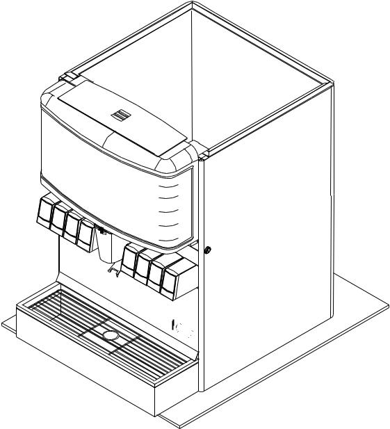
1.3SELECTING COUNTER LOCATION (SEE FIGURE 1)
WARNING THIS APPLIANCE MUST BE EARTHED. THIS DISPENSER MUST BE ELECTRICALLY GROUNDED TO
AVOID DANGER TO THE OPERATOR. THE POWER CORD PROVIDED HAS A THREE PRONG GROUNDED PLUG. IF A THREE HOLE GROUNDED ELECTRICAL OUTLET IS NOT AVAILABLE, USE AN APPROVED METHOD OF
INSURING A PROPER GROUND TO THE DISPENSER.
ADVERTENCIA
!CONEXIÓN A TIERRA PARA EVITAR PELIGRO PARA EL OPERADOR. EL CABLE SUMINISTRADO TIENE UN
ENCHUFE DE TIERRA DE TRES PUNTAS. SI UN AGUJERO TRES TOMACORRIENTE PUESTO A TIERRA NO ESTÁ
DISPONIBLE, UTILICE UN MÉTODO APROBADO DE ASEGURAR UNA TIERRA CORRESPONDIENTE EN LA CUBETA.
AVERTISSEMENT CET APPAREIL DOIT ETRE MIS A LA TERRE. CE DISTRIBUTEUR DOIT ÊTRE MIS À LA TERRE ÉLECTRIQUE POUR ÉVITER DANGER POUR L’OPÉRATEUR. LE CORDON D’ALIMENTATION FOURNIS A UN TROIS BROCHES TERRE. SI UN TROIS TROUS TERRE ALIMENTATION ÉLECTRIQUE N’EST DISPONIBLE, UTILISER UNE MÉTHODE APPROUVÉE D’ASSURER UN MOTIF VALABLE AU DISTRIBUTEUR.
A.Select a location close to a properly grounded electrical outlet, convenient to an open type drain, access for soda, water, and syrup lines, and sufficient clearance for air circulation.
1.If at all possible, location should be away from direct sunlight or other heat sources.
2.Connecting lines may be run through access in back of the unit or extend down through a counter cut out.
3.The counter must support the weight of the dispenser, ice, and possibly an ice maker. Total weight may exceed 800 lbs (363.6 kg).
B.Unit may be installed directly on the countertop or on legs supplied with the unit. If installed
directly on the counter, the unit must be sealed to the countertop. If an ice maker is to be mounted on top of dispenser, do not install dispenser on legs.ESTE APARATO DEBE CONECTARSE A TIERRA. ESTE DISPENSADOR DEBE TENER
FIGURE 1.
ENSURE KEY SWITCH
IS ACCESSIBLE
9 3/4” (248 MM) DISPENSE HEIGHT
MINIMUM of 6" (152 mm) clearance above ice maker
R |
T |
|
T |
AI |
|
|
OU |
OU |
AIR |
||
|
|
|
|
SUFFICIENT CLEARANCE FOR |
|
|
|
|
FILLING MANUALLY WITH ICE, |
|
OU |
AIR |
T |
WHEN ICE MAKER NOT USED |
R |
T |
OU |
|
|
AI |
|
|
|
(92536” MM) |
clearancemm) |
clearancemm) |
mm)(86434" |
|
|
I C E |
|
|
|
PUSH |
|
|
6"(152 |
6"(152 |
|
|
|
22" (559 mm) |
|
MINIMUM of 6" (152 mm) clearance above ice maker
IN
R
AI
AIR |
IN |
|
|
of6"(152mm) clearance |
|
MINIMUM wall |
|
30 1/2" (775 mm)
10
1.3SELECTING COUNTER LOCATION (CONTINUED)
NOTE: Water pipe connections and fixtures directly connected to a potable water supply must all be sized, installed, and maintained according to Federal, State, and Local laws. The water supply must be protected by means of an air gap, a backflow prevention device (located upstream of the CO2 injection system) or another approved method to comply with NSF standards. A backflow prevention device must comply with ASSE and local standards. It is the responsibility of the installer to ensure compliance.
C.Location must insure sufficient clearance on sides, top and back of unit is provided for ventilation and air circulation (see Figure 1).
D.Additionally, if an ice maker is not top mounted on the unit, sufficient clearance should be provided [a minimum of 16 inches (40.6 cm) is recommended] to allow filling the unit with ice from a five (5) gallon (19 liter) container (see Figure 1).
1.4INSTALLING THE DISPENSER
A.Remove Cup Rest, Drip Tray, Splash Plate, and Top Cover.
B.Remove Cover Plate at rear of unit if not a through the counter installation.
C.Connect soda and water supply lines to 3/8 inch barb fittings at the front of the unit. Check for leaks. (If dispenser is to operate with all soda valves, connect water line into one of the soda supply lines.)
D.Connect syrup supply lines to the 3/8 inch barb inlet fittings at the front of the unit. Check for leaks.
E.Uncoil drain hose from Cold Plate drain and extend to an open type drain.
F.Install Drip Tray and extend hose to open type drain.
G.Both drain lines must be insulated with a closed cell insulation. Insulation must cover the entire length of the drain hose, including fittings. The drain should be installed in such a manner that water does not collect in sags or other low points, as condensation will form.
H.Install Cup Rest and Splash Plate.
I.Connect Power Cord to grounded electrical outlet.
J.Test Motor operation by pushing Ice Chute.
K.Clean and sanitize dispenser (see Section 2).
L.Fill unit approximately half full with ice. Push Chute and check for ice delivery.
M.Finish filling unit with ice.
N.Install Top Cover.
NOTE: Lancer does not recommend the use of shaved, flake, nugget, or pellet ice in dispensers not properly equipped to do so.
O. Set brix ratio for beverage dispensing valves according to manufacturer’s instructions.
WARNING WHEN INSTALLING AN ICEMAKER ON AN IBD UNIT, A BIN THERMOSTAT OR OTHER MEANS
OF CONTROLLING THE ICE LEVEL MUST BE INSTALLED. FAILURE TO DO SO COULD RESULT IN DAMAGE TO THE DISPENSING MECHANISM AND VOID THE WARRANTY. DURING THE AUTOMATIC AGITATION CYCLE AND/OR WHILE DISPENSING ICE, THERE MUST BE ADEQUATE ROOM BETWEEN THE TOP OF THE ICE LEVEL AND THE BOTTOM OF THE ICEMAKER SO THAT THE ICE CAN MOVE WITHOUT OBSTRUCTION. CONTACT YOUR
ICEMAKER SUPPLIER FOR INFORMATION ON PROPER BIN THERMOSTAT.
ADVERTENCIA AL INSTALAR UNA MÁQUINA DE HIELO EN UNA UNIDAD DE IBD, A BIN TERMOSTATO U OTROS
MEDIOS DE CONTROLAR EL NIVEL ICE DEBE ESTAR INSTALADO. NO HACERLO PUEDE CAUSAR
!DAÑOS AL MECANISMO DISPENSING Y ANULAR LA GARANTÍA. DURANTE EL CICLO AUTOMÁTICO AGITACIÓN Y
/ O HIELO, MIENTRAS QUE LA DISPENSACIÓN, DEBE HABER ESPACIO SUFICIENTE ENTRE EL TOP DEL NIVEL DE HIELO Y EL FONDO DE LA MÁQUINA DE HIELO PARA QUE EL ICE PUEDE MOVERSE SIN OBSTRUCCIÓN. CONTACTO CON SU PROVEEDOR DE FABRICACIÓN DE HIELO PARA INFORMACIÓN SOBRE ADECUADO BIN
TERMOSTATO.
AVERTISSEMENT LORSQUE VOUS INSTALLEZ UNE MACHINE À GLAÇONS SUR UNE UNITÉ EIA, UN
THERMOSTAT DU BAC OU AUTRES MOYENS DE CONTRÔLER LE NIVEAU DE LA CIE DOIT ÊTRE INSTALLÉ. PANNE DE LE FAIRE POURRAIT PROVOQUER DES DOMMAGES AU MÉCANISME DE DISTRIBUTION ET ANNULE LA GARANTIE. PENDANT LE CYCLE AUTOMATIQUE AGITATION ET / OU TOUT DISTRIBUTION DE GLACE, DOIVENT TROUVER PLACE SUFFISANTE ENTRE LE SOMMET DE L’ÉCHELLE DE L’ICE ET LE BAS DE LA MACHINE À GLAÇONS POUR QUE LA GLACE PEUT SE DÉPLACER SANS ENTRAVE. CONTACTEZ VOTRE
FOURNISSEUR DE ICEMAKER INFORMATIONS SUR UNE BONNE THERMOSTAT DU BAC.
11
 Loading...