


COLD CARB ICE COOLED DISPENSER SERIES 2308 - DROP IN
Installation and Service Manual
PN 28-0720/05 11/10/09
LANCER
6655 Lancer Blvd.
San Antonio, Texas 78219
To order parts, call Customer Service: 800-729-1500 Warranty/Technical Support: 800-729-1550 Email: custserv@lancercorp.com www.lancercorp.com
ISO 9001:2000 Quality System Certified
“Lancer” is the registered trademark of Lancer © 2009 by Lancer, all rights reserved.
TABLE OF CONTENTS
SPECIFICATIONS.............................................................................................................................................. |
3 |
||
1. INSTALLATION OF LANCER ICE COOLED DISPENSER........................................................................ |
3 |
||
|
1.1 |
RECEIVING........................................................................................................................................ |
3 |
|
1.2 |
UNPACKING ...................................................................................................................................... |
3 |
|
1.3 |
SELECTING A COUNTER LOCATION.............................................................................................. |
3 |
|
1.4 |
WATER SUPPLY................................................................................................................................ |
3 |
|
1.5 |
ELECTRICAL SUPPLY ...................................................................................................................... |
4 |
|
1.6 |
INSTALLATION OF THE DISPENSER AND PUMP DECK ............................................................... |
4 |
|
1.7 |
CONNECTION OF THE EQUIPMENT .............................................................................................. |
5 |
|
1.8 |
START UP .......................................................................................................................................... |
5 |
|
1.9 |
ADJUSTING WATER FLOW.............................................................................................................. |
6 |
|
1.10 |
ADJUSTING WATER TO SYRUP RATIO (BRIX) .............................................................................. |
7 |
|
1.11 |
CONVERTER BLOCK........................................................................................................................ |
7 |
2. |
MVU OPERATION....................................................................................................................................... |
8 |
|
|
2.1 |
MVU PLUMBING DIAGRAM - MAKING CONNECTIONS TO THE MVU ......................................... |
8 |
|
2.2 |
SYSTEM STARTUP ........................................................................................................................... |
8 |
|
2.3 |
PROGRAM MULTI VALVE UNIT (MVU) ............................................................................................ |
9 |
|
2.4 |
SET MVU FOR FLAVOR SHOTS .................................................................................................... |
10 |
|
2.5 |
FLOW RATE CHECK....................................................................................................................... |
12 |
|
2.6 |
RATIO PROCESS ............................................................................................................................ |
13 |
|
2.7 |
PORTION CONTROL PROGRAMMING (MVU) (NO TOPOFF)...................................................... |
14 |
|
2.8 |
PORTION CONTROL PROGRAMMING WITH TOP-OFF (MVU)................................................... |
15 |
|
2.9 |
SHOT SIZE PROGRAMMING ......................................................................................................... |
17 |
|
2.10 |
DISPENSER OPERATION............................................................................................................... |
18 |
|
2.11 |
FINAL ASSEMBLY ........................................................................................................................... |
19 |
3. RECOMMENDED SERVICES AND MAINTENANCE............................................................................... |
20 |
||
|
3.1 |
SCHEDULED ................................................................................................................................... |
20 |
|
3.2 |
CLEANING AND SANITIZING SYSTEMS ....................................................................................... |
20 |
|
3.3 |
CLEANING AND SANITIZING BAG-IN-BOX (BIB) SYSTEMS ....................................................... |
21 |
|
3.4 |
VALVES ............................................................................................................................................ |
21 |
|
3.5 |
ICE BIN COMPARTMENT ON ALL ICE CHESTS ........................................................................... |
22 |
4. |
TROUBLESHOOTING............................................................................................................................... |
23 |
|
|
4.1 |
NO CARBONATION......................................................................................................................... |
23 |
|
4.2 |
NOISY CARBONATOR PUMP......................................................................................................... |
23 |
|
4.3 |
VALVES INOPERABLE.................................................................................................................... |
23 |
|
4.4 |
LED BLINKING 4 BLINKS PER SECOND....................................................................................... |
24 |
|
4.5 |
LED BLINKING 1 BLINK PER SECOND......................................................................................... |
24 |
5. ILLUSTRATIONS, PARTS LISTINGS AND WIRING DIAGRAMS........................................................... |
26 |
||
|
5.1 |
SERIES 2300 DROP-IN.............................................................................................................. |
26-27 |
|
5.2 |
REMOTE PUMP ASSEMBLY ..................................................................................................... |
28-29 |
|
5.3 |
TOWER ASSEMBLY, BEVARIETY MVU .................................................................................... |
30-31 |
|
5.4 |
MVU ASSY....................................................................................................................................... |
32 |
|
5.5 |
NOZZLE, HYBRID MULTI-FLAVOR................................................................................................. |
32 |
|
5.6 |
ICE COOLED UNIVERSAL WIRING DIAGRAM WITH BIN LID SWITCH ...................................... |
33 |
|
5.7 |
ICE COOLED UNIVERSAL WIRING DIAGRAM WITH BIN LID SWITCH AND MVU .................... |
34 |
|
5.8 |
ACCESSORIES................................................................................................................................ |
35 |
P.N. 28-0720/05 |
2 |

SPECIFICATIONS
DIMENSIONS |
|
|
|
Cabinet |
23 inches x 23 inches |
(58.42 cm x 58.42 cm) |
|
Rim |
25 inches x 25 inches |
(63.50 cm x 63.50 cm) |
|
Height (without legs) |
19-1/2 inches |
|
(49.53 cm) above counter (to top |
|
|
|
of valves) |
|
23 inches |
|
(58.42 cm) below counter |
WEIGHT |
|
|
|
Shipping |
296 pounds |
(134.26 kg) |
|
Empty |
253 pounds |
(114.75 kg) |
|
Operating |
365 pounds |
(165.5 kg) |
|
ICE BIN CAPACITY |
100 pounds |
(45.46 kg) |
|
Pouring coffee, tea, and like substances into the drain can cause clogging.
WARNING!
1.INSTALLATION OF LANCER ICE COOLED DISPENSER
1.1RECEIVING
Each unit is tested under operating conditions and inspected before shipment. At the time of shipment, the carrier accepts responsibility for the unit. Upon receiving the unit, carefully inspect the carton for visible damage. If damage exists, have the carrier note the damage on the freight bill and file a claim with carrier. Responsibility for damage to the unit lies with the carrier.
1.2UNPACKING
A.The ice cooled dispenser is shipped in a corrugated shipping carton. Remove the corrugated shipping carton from the unit.
B.Remove the parts from the ice compartment.
C.Inspect the unit and parts for concealed damage. If damage exists, notify delivering carrier and file a claim.
1.3SELECTING A COUNTER LOCATION
A.Select a counter location close to a properly grounded electrical outlet and a water supply that meets the requirements specified in Section 1.4 below.
B.The counter location must be able to safely support a minimum of 365 pounds (165.5 kg) after the counter cutout is made.
1.4WATER SUPPLY
A.Provide an adequate potable water supply The water supply line must be at least a 1/2 inches (12.7 mm) pipe. Water pressure exceeding 50 PSI is regulated by a pressure regulator on the pump deck. Water pressure below 40 PSI will require a booster pump.
B.Install a shut-off valve in the water line feeding the deck. If a separate water line is run for plain water, ensure that it also has a shut-off valve.
3 |
P.N. 28-0720/05 |

Use a filter in the water line to avoid damage to the dispenser.
WARNING!
C.The carbonator pump is equipped with a strainer on the inlet side. A water supply containing any appreciable quantity of silt, fine sand, or other debris requires a filter ahead of the pump deck. Clean the filter cartridge periodically, depending on the condition of the water. Failure to do so may starve the pump of water, causing it to burn out, and voiding the warranty.
1.5ELECTRICAL SUPPLY
The dispenser must be properly electrically grounded to avoid serious injury or fatal electrical shock. The power cord has a three-prong grounded plug. If a three-hole grounded electrical outlet is not available, use an approved method to ground the unit. Follow all local electrical codes when making connections. Each dispenser must have a separate electrical circuit. Do not use extension cords. Do not connect multiple electrical devices on the same outlet.
ALWAYS disconnect power to the dispenser before attempting any internal maintenance.
Only qualified personnel should service the internal components of the dispenser. Avoid any contact with water when plugging in the dispenser.
A.Locate a standard 20 AMP, 110 VAC, 60 Hz single phase electrical power outlet with ground connectors for the dispenser and pump deck.
1.6INSTALLATION OF THE DISPENSER AND PUMP DECK
A Inspect the counter location where the dispenser will be installed. Verify that the counter is strong enough to safely support a 365 pound (165.5 kg) load, after the counter cutout is made.
B.Verify that the unit will fit in the location. See below for the counter cutout dimensions.
NOTE: The unit can extend up to 23 inches (58.42 cm) below the counter, including the shipping risers. It is recommended to keep the shipping risers attached to the dispenser. If the dispenser ever requires removal, the shipping risers will protect the inlet tubes from being damaged.
23 1/4"
23 1/4"
Counter Cutout for dispenser
P.N. 28-0720/05 |
4 |

C. After the counter cutout is made, lower the dispenser into the counter.
NOTE: In order to ensure unit drainage and proper carbonation, it is necessary for the dispenser to be level, front to back and side to side.
D.Position the pump deck under the counter within close proximity to the dispenser. The pump deck must be on a level surface and have adequate electrical utilities available.
1.7CONNECTION OF THE EQUIPMENT
A.Position the CO2 gas tank in the desired location. Assemble the high pressure regulator to the CO2 gas tank and run the jumper line to the low pressure regulator.
B.Attach the CO2 gas line to the carbonator by attaching the line from the high pressure regulator to the CO2 inlet. The setting of the high pressure CO2 gas regulator should be 75 PSI.
Do not turn on CO2 at this time.
WARNING!
C.Position the syrup pumps in the desired location. Attach the CO2 gas lines leading from the low pressure regulator to these pumps.
D.Connect the syrup lines from the pumps to the appropriate inlets at the front of the unit. The syrup inlets are identified at the bottom of the unit.
E.Connect the water inlet line to the pump. Complete the water line connection between the pump and the water inlet to the carbonator at the bottom of the dispenser.
F.Provide a suitable drain in the plumbing system and attach the 3/4 inch (1.90 cm) diameter schedule 40 PVC drains to it. The drip pan drainage outlet is located at the right rear of the unit. The ice water drainage outlet is located at the right front of the unit.
G.Be sure to place the ice trap in the drain outlet inside the ice bin before filling with ice. This device holds the ice away from the drain outlet, allowing the ice water to drain properly.
H.Plug in the transformer box to a standard 20 AMP, 110 VAC, single phase outlet. The unit will internally convert the 110 VAC to 24 VAC.
1.8START UP
A.After all connections to water, CO2 gas, electrical power, and syrup pumps are made, check for leaks.
B.Be sure the Bag-In-Box contains syrup.
Do not operate the carbonator pump deck with the water supply turned off.
WARNING!
C.Turn on water. Open the pressure relief valve on the carbonator tank by flipping up the valve cap lever, and hold it open until water flows from the relief valve. Close (flip down) the relief valve and turn on the CO2 gas.
D.To fill all lines with water, cycle the carbonator several times by operating the dispensing valves.
1.Ensure a good flow of plain water is established from each valve.
2.Turn on CO2 at source and ensure that the HP regulator is set at 75 PSIG.
3.Operate valves until unit gases out.
4.Plug in carbonator pump motor. Pump Deck will automatically start.
5 |
P.N. 28-0720/05 |
5.Activate carbonated water valves so that the carbonator pump cycles several times and a good flow of carbonated water is established.
6.A low pressure gas regulator controls the flow of syrup to each dispensing valve. Connect BIB connectors to BIB’s. Set LP regulator to 65 PSIG. Activate all valves to purge air from the syrup lines.
NOTE: The unit will cycle on for 5.5 seconds, shut down, and immmediately start again and run for additional 5.5 second intervals until the water level reaches the probe.
E.The dispenser bin should now be filled with ice cubes one inch below the level of the door opening.
1.9ADJUSTING WATER FLOW
A.The water flow can be adjusted to either 1.25 ounces/second (37 ml/sec) or 2.5 ounces/second (74 ml/sec) on all dispensing valves, using the following procedure.
NOTE: The unit should have ice on the cold plate for a least one hour before you attempt to brix the valves. The drink temperature should be no higher than 40oF (4.4oC) when the ratio is set. This is done after the unit has ice in the ice bin.
C.Slide the ID panel up until the flow controls are exposed (see below).
D.Remove the nozzle by twisting counterclockwise and pulling down.
E.Remove the diffuser by pulling down.
F.Install Lancer yellow syrup separator (PN 54-0031) in place of the nozzle.
G.Activate the dispensing valve to fill the separator syrup tube.
H.Hold a brix cup under the syrup separator and dispense water and syrup into the cup for four seconds. Divide the number of ounces (ml) of water in the cup by four to determine the water flow rate per second.
I.To obtain the proper flow, use a screwdriver to adjust the water flow control.
J.Repeat process for each valve.
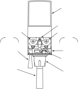
I.D. PANEL (Shown in open position)
COVER SCREW
FLOW CONTROL |
FLOW CONTROL |
SYRUP |
SYRUP |
||
Increase |
Decrease |
Increase |
Decrease |
SODA LEVER |
COVER |
||
(Optional) |
|
|
|
|
|
DATE OF |
|
|
|
MANUFACTURE |
|
|
|
SERIES NO. |
|
CUP LEVER |
|
|
|
|
|
NOZZLE |
|
Valve Adjustments
P.N. 28-0720/05 |
6 |

1.10ADJUSTING WATER TO SYRUP RATIO (BRIX)
A.Hold the brix cup under the syrup separator and activate valve. Check ratio (brix).
B.To obtain the proper ratio, use screwdriver to adjust syrup flow control (see Figure 2).
C.Remove syrup separator.
D.Install diffuser and nozzle.
E.Slide ID panel DOWN.
F.Repeat process for each valve.
NOTE: When re-assembling valves with o-rings, ensure the o-ring is lubricated with an FDAapproved lubricant or water to prevent leakage or damage to the o-ring.
1.11CONVERTER BLOCK
A.Set the converter block to provide either plain or carbonated water, depending on the product. The alignment of the dot on the converter block signifies the active port (plain water or carbonated water):
B.To remove the converter block, use a small screwdriver in the blind hole to pry the converter block out. Applying pressure opposite the blind hole (dot side) will facilitate removing the converter block:
7 |
P.N. 28-0720/05 |

2.MVU OPERATION
2.1MVU PLUMBING DIAGRAM - MAKING CONNECTIONS TO THE MVU
A.Valves 1-3 and 6-8 are in the normal positions on the tower; however, the MVU is plumbed as shown in the diagram below. Position A is syrup inlet #4 on the cold plate. Position D is syrup inlet #5. Positions B, C, E, and F on the MVU connect in the positions shown on the illustration of the Configurator block. These positions (B, C, E, F) are all ambient (bypass the cold plate).
2.2SYSTEM STARTUP
A.Turn on water and purge lines.
B.Turn on CO2 and gas out dispenser.
C.Plug in carbonator pump.
D.Cycle valves two times.
E.Turn on CO2 to BIB pumps.
F.Pour several drinks.
G.Prime for flavor shots.
H.Prime for beverages.
P.N. 28-0720/05 |
8 |

2.3PROGRAM MULTI VALVE UNIT (MVU)
Set MVU Buttons as Carbonated, Non-Carbonated, or Flavor Shot Only.
The MVU can be programmed to serve soda or plain water beverages as well as a flavor shot from each of the beverage positions on the valve.
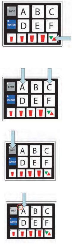
To enter the programming mode on the MVU and assign water type to each individual brand (Carbonated or Non-carb):
A.Press both A and C brand buttons at the same time on the MVU panel for five seconds.
1.The “Pour/Cancel” LED will illuminate. The “SHOT” LED will blink one time.
2.Brands that are enabled for drinks will have illuminated LED’s:
Lights on = non-carb
Lights flashing = carb
Lights off = no water (deactivated unless set for shot)
B.Press a Brand button to change that beverage from “water off” to “plain water on”.
1. LED will illuminate and stay on for noncarb beverages.
C. Press the same brand button again to switch from non-carb to carb.
1. Press the button one more time to turn the water off for that valve (if position is used for a flavor shot only).
D. Repeat this process for each brand.
9 |
P.N. 28-0720/05 |
E.Press the Pour/Cancel button to lock the changes in place and exit the programming mode.
NOTE: The Program will save automatically in 60 seconds if no additional changes are made in that time frame; however, you can exit any time within the 60 second window by pressing Pour/Cancel. The changes you’ve made will be saved.
2.4SET MVU FOR FLAVOR SHOTS
A. Press both A and C brand buttons (at the same time) on the MVU panel for five seconds to get into programming mode.
B. Press the “Shot” button.
1.The “Shot” button will illuminate.
2.Brands enabled for shots will be illuminated.
C.Press the “Brand” button to turn the shot mode for that brand on or off.
1. The shot mode is “ON” in the illustration.
P.N. 28-0720/05 |
10 |
D. Press “Shot” again to return to “Drink Type Selection”
E.Press the Pour/Cancel Button to lock the changes in place and exit the programming mode.
NOTE: The Program will save automatically in 60 seconds if no additional changes are made in that time frame; however, you can exit any time within the 60 second window by pressing Pour/Cancel. The changes you’ve made will be saved.
11 |
P.N. 28-0720/05 |
 Loading...