

Page 1
manual
gs3
Imagine if the sky’s the limit, what would the ultimate light duty/home
machine be? That was the question La Marzocco set out to answer.
Years of research and development yielded the creation of a yet another
standard setting espresso machine: the GS/3. With La Marzocco performance
and technology, the GS/3 is designed for light commercial applications,
including restaurants, ofces, catering, or the ultimate home coffee bar. All
the features and performance of a larger La Marzocco in a compact footprint.
Page 2
gs3
La Marzocco S.r.l.
Via La Torre 14/H
Località La Torre
50038 Scarperia e San Piero
(Firenze) - ITALIA
www.lamarzocco.com
info@lamarzocco.com
T: +39 055 849 191
F: +39 055 849 1990
Operating Manual V1.3 - 09/2016
MAN.2.1.01
EN
certications available:
Chapters
1. General Information
2. Accessories
3. Machina Description
4. Installation
5. Operation
6. Key Features
7. Preventative Maintenance and Cleaning
8. Maintenance and Periodic Cleaning Operations
9. Installation Guide
10. Software Programming Guide
page 3
page 5
page 6
page 7
page 12
page 14
page 16
page 18
page 19
page 29
Page 3
EN
1. General Information
WARNING
THIS MACHINE IS FOR PROFESSIONAL USE ONLY
AND SHOULD BE INSTALLED IN LOCATIONS WHERE
ITS USE AND MAINTENANCE IS RESTRICED TO
TRAINED PERSONNEL. CHILDREN ARE FORBIDDEN TO
OPERATE OR PLAY WITH THE MACHINE.
About this Manual
1) This operating guide is an integral and
essential part of the product and must be
supplied to users. Users are asked to read
the enclosed warnings and cautions
carefully, as they provide valuable
information concerning safety during
installation, operation, and maintenance.
This manual must be kept in a safe place
and be available for consultation to new
and experienced users alike.
Remove Machine from Packaging
1) Ensure product’s integrity by inspecting
the packaging, making sure it presents
no signs of damage which might have
affected the enclosed machine.
2) Check the machine’s integrity after
having carefully removed the packaging.
Packaging (boxes, plastic bags, foam parts
and whatever else) must not be left within
easy reach of children, due to the potential
danger it represents, nor be discarded in
the environment.
Safety Instructions
1) Check to see that data on the rating
plate corresponds to those of the main
electrical supply to which the machine will
be attached.
This equipment must be installed to
comply with applicable federal, state or
local plumbing codes.
2) The installation must be performed
according to local electrical and plumbing
codes and regulations. The installation
also must comply to the manufacturer’s
instructions, and must be performed by
qualied and authorized personnel.
3) Incorrect installation may cause injury/
damages to people, animals or objects, for
which the manufacturer shall not be held
responsible.
4) Safe electrical operation of this device
will be achieved only when the connection
to the power outlet has been completed
correctly and in observance of all local,
national, and international electrical codes
and safety regulations, and particularly by
grounding the unit. Make sure grounding
has been done properly as it represents a
fundamental safety requirement. Ensure
qualied personnel check such connection.
5) Furthermore, you must ensure that
the capacity of the available electrical
system is suitable for the maximum power
consumption indicated on the espresso
machine.
6) We do not recommend using adapters,
multiple plugs and/or extension cords.
If you cannot avoid using them, make
sure that they are exclusively of the kind
which conforms to local, national, and
international electrical codes and safety
regulations, being careful not to exceed
the power and current ratings indicated on
such adapters and extension cords.
WARNING
THE MANUFACTURER DECLINES ANY RESPONSIBILITY
FOR ANY EVENT LEADING TO LIABILITY SUITS
WHENEVER GROUNDING HAS NOT BEEN COMPLETED
ACCORDING TO CURRENT LOCAL, NATIONAL, AND
INTERNATIONAL REGULATIONS AND ELECTRICAL
CODES, OR OTHER ELECTRICAL PARTS HAVE BEEN
CONNECTED IMPROPERLY.
7) This device must be used exclusively for
the functions it has been designed and built
for. Any other application is inappropriate
and dangerous.
The manufacturer shall not be held
responsible for any damages caused by
improper and/or irrational use. This machine
should not be installed in kitchens.
3
Page 4
EN
8) Using any electrical device requires that
certain fundamental rules be observed. In
particular:
- do not touch the device with wet or
moist hands and feet
- do not use the device while not wearing
shoes
- do not use extension cords in bath or
shower rooms
- do not unplug the device from the power
outlet by pulling on the power supply
cable
- do not expose the device to atmospheric
agents
- do not allow children or untrained people
to use this device
9) Before performing any maintenance and/
or cleaning operations (other than back-
ushing the group), turn the main switch
to the “0” or OFF position, and disconnect
the machine from the electrical network
by unplugging the cord or by switching
off the relative circuit breaker. For any
cleaning operation, follow exclusively the
instructions contained in this manual.
WARNING
HAZARDOUS VOLTAGE DISCONNECT FROM POWER
SUPPLY BEFORE SERVICING.
10) If the machine is operating in a faulty
manner or stops working, disconnect it
from the electrical network (as described
in the preceding point). Do not attempt
to repair it. Contact a qualied and
authorized professional to perform any
repair. Any repair must be performed
exclusively by the manufacturer or by
an authorized centre using only original
parts. Non compliance with the above
could compromise the safe operation of
the machine.
WARNING
THE MACHINE MUST BE INSTALLED SO THAT
QUALIFIED TECHNICAL PERSONNEL CAN EASILY
ACCESS IT FOR MAINTENANCE.
11) In order to avoid dangerous overheating
problems, it is recommended that the
power supply cable be unfurled completely.
12) Do not obstruct air intake and exhaust
grilles and, in particular, do not cover the
cup warmer tray with cloths or other items.
Minimum room temperature: 5°C
Maximum room temperature: 32°C
13) The machine’s power supply cable
must not be replaced by users. In case the
power supply cable becomes damaged,
shut off the machine and disconnect the
machine from the electrical network by
unpluging the power cord or switching off
the relative circuit breaker and close off the
water supply; to replace the power supply
cord, contact qualied professionals
exclusively.
WARNING
THIS APPLIANCE IS NOT INTENDED FOR USE BY
PERSONS (INCLUDING CHILDREN) WITH REDUCED
PHYSICAL, SENSORY OR MENTAL CAPABILITIES,
OR LACK OF EXPERIENCE AND KNOWLEDGE,
UNLESS THEY HAVE BEEN GIVEN SUPERVISION OR
INSTRUCTION CONCERNING USE OF THE APPLIANCE
BY A PERSON RESPONSIBLE FOR THEIR SAFETY.
WARNING
IN ORDER TO PREVENT CRACKS OR LEAKAGE: DO
NOT STORE OR INSTALL THE COFFEE MACHINE IN
PLACES WHERE TEMPERATURE MAY CAUSE BOILER OR
HYDRAULIC SYSTEM WATER FREEZING.
4
Page 5
EN
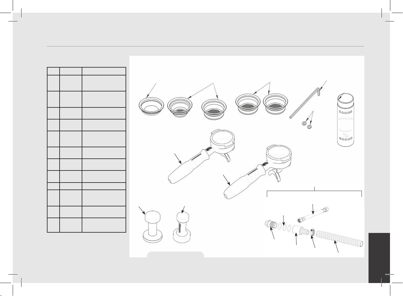
Check the package to make sure that the following accessories are included in the packaging:
QTY. PART NO. DESCRIPTION
L111/2NAC
1
1 L111/1AC PORTAFILTER
1 L115/C PORTAFILTER BASKET,
1 F.3.029 PRECISION FILTER
1 F.3.028 PRECISION FILTER
1 F.3.027 PRECISION FILTER
1 F.3.026 PRECISION FILTER
1 F.3.030/
F.3.031
1 UT003 HEX KEY, 5mm
2 L120/2A WASHER, FLAT,
1 V067 ESPRESSO MACHINE
1 913 (CE)
914 (ETL)
PORTAFILTER
ASSEMBLY, DOUBLE
SPOUT, S/STEEL
ASSEMBLY, SINGLE
SPOUT, S/STEEL
BLIND
BASKET 7gr (SINGLE)
BASKET 14gr
(DOUBLE)
BASKET 17gr
BASKET 21gr
TAMPER (ACCORDING
TO MARKET)
SEALING TYPE, M6
(12X6.25X0.75)
CLEANER
WATER SUPPLY AND
DRAIN CONNECTION
KIT
L115/C
L111/1AC
F.3.031.01(U.S.A.) F.3.030.01
F.3.029 F.3.028.01 F.3.027.01 F.3.026.01
L111/2NAC
2. Accessories
UT003
V067
L120/2A
913 (CE) / 914 (ETL-USA)
L325 (CE)
L326 (ETL-USA)
H.1.010.01
Figure 1 - Accessories
F.8.002
F.8.003
L312
L308
5
Page 6
EN
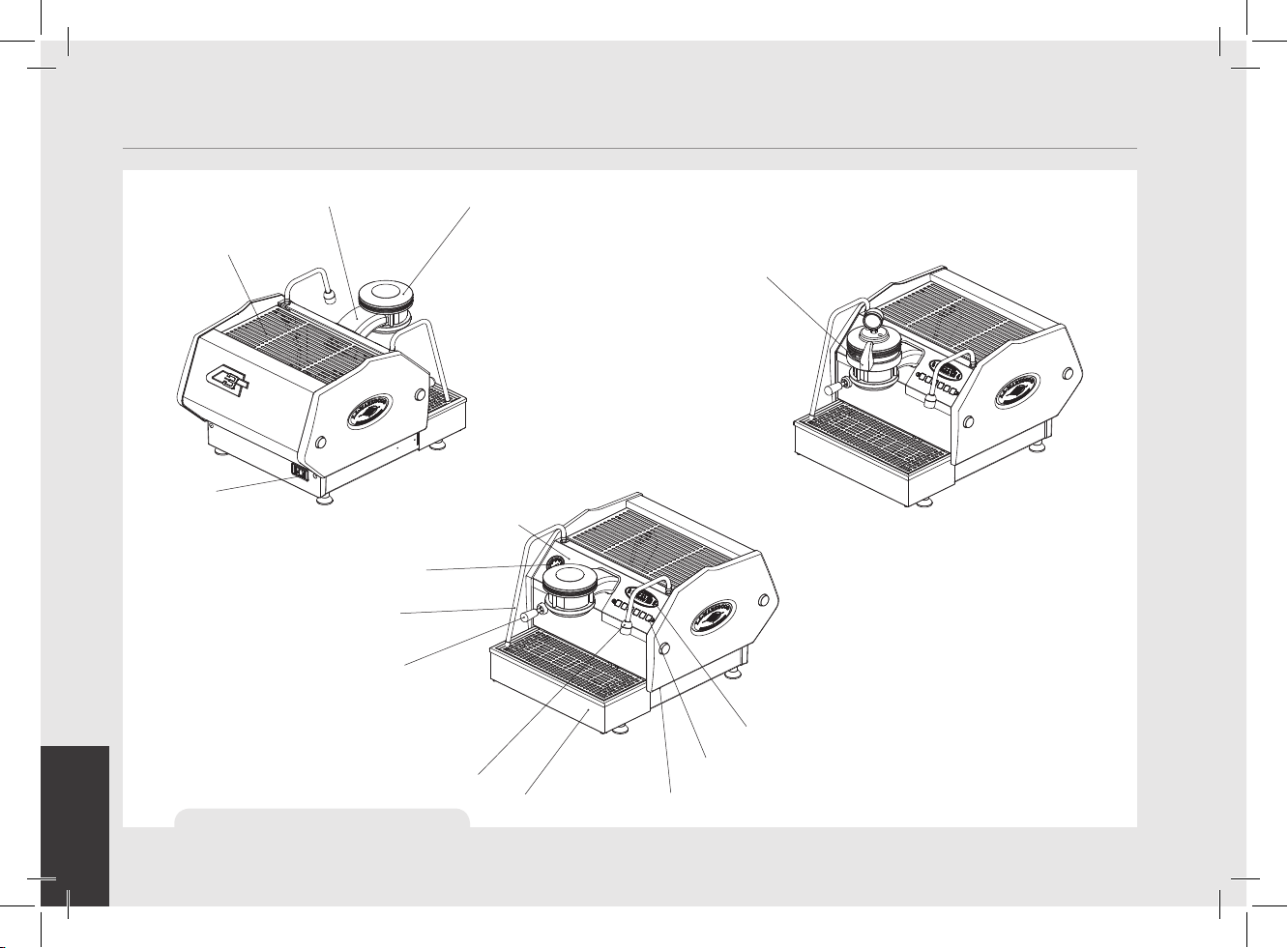
3. Machine Description
cup tray
main power switch
6
Figure 2 - Machine Description
group head
(AV model)
pressure gauge
(coffee boiler)
steam wand
steam activation
lever
hot water dispensing
pressure gauge
(steam boiler)
spout
group cover
drain box
paddle group and handle
(MP model)
display
keypad
temperature adjustment
knob for hot water
Page 7

EN
4. Installation
THE MACHINE IS INTENDED TO BE PERMANENTLY
WARNING
CONNECTED TO MAINS POWER SUPPLY.
IT IS MANDATORY THAT A RESIDUAL CURRENT DEVICE
(RCD) WITH A RATED RESIDUAL OPERATING CURRENT NOT
EXCEEDING 30 mA IS INSTALLED.
Espresso Machine Installation, GS/3
1) Fill Water reservoir with potable water.
Remove the drain tray and slide the
water reservoir until the water reservoir
ll cover is accessible. Remove the cover
and ll water reservoir with potable water.
Replace the ll cover and slide the water
reservoir to the operating position and
replace the drain tray. (See GS/3 Software
and Installation Guide for additional
instructions). In order to connect the
machine up to the water mains proceed
according to the indications given in the
Installation Guide and in compliance with
any local/national safety standards of the
location in which the machine is being
installed.
To guarantee a correct and safe functioning
of the machine and to maintain an
adequate performance level and a high
quality of the beverages being brewed it
is important that the incoming water be
of a hardness greater than 7°f (70ppm,
4°d) and less than 10°f (100ppm, 6°d),
pH should be between 6.5 and 8.5 and
the quantity of chlorides be less than
50mg/l . Respecting these values allows
the machine to operate at maximum
efciency. If these parameters are not
present, a specic ltration device should
be installed, while always adhering to the
local national standards in place regarding
potable water.
In order to enable
you to check
if your water
supply is within
the suggested
ranges, La
Marzocco
machines will be
equipped with
two units of a
quick water test
kit (see image
below) including
6 test-strips and
instruction cards.
The parameters that you can measure are
Total Hardness, Total Iron, Free Chlorine,
Total Chlorine, pH & Total Alkalinity,
Chlorides.
Ideally, you should perform a test on the
water BEFORE the water treatment system
and again AFTER the water system in
order to verify if this is actually matching
our suggested ranges.
Once the test has been performed,
learn which treatment system is most
appropriate for your particular water supply
by lling out the online water calculator
on our website: LA MARZOCCO WATER
CALCULATOR (http://www.lamarzocco.
com/water_calculator/).
WARNING
THE COFFEE MACHINE MUST BE PLACED IN A
HORIZONTAL POSITION ON A COUNTER HIGHER THAN 80
CM FROM THE GROUND
2) Connect Espresso Machine to Power Supply.
Connect the espresso machine to a power
supply that is rated in accordance with the
serial plate on the espresso machine.
3) Filling the Boilers with Water.
Once the espresso machine has been
unpackaged, placed on a hard surface,
and with the water reservoir full, it will
be necessary to ll the boilers with water.
Complete the following steps to properly
ll the boiler tanks:
Steam Boiler: Turn the main switch to
position “1” or ON, the automatic steam
boiler level system will be switched on,
activating the auto-ll solenoid valve and
the water pump. This will ll the steam
7
Page 8
EN
boiler to a predetermined level and will
shut off when full.
NOTE: It may be necessary to re-ll the water
reservoir during this process. Check to see if the
“Water Tank Empty” error message is present on
the display before continuing.
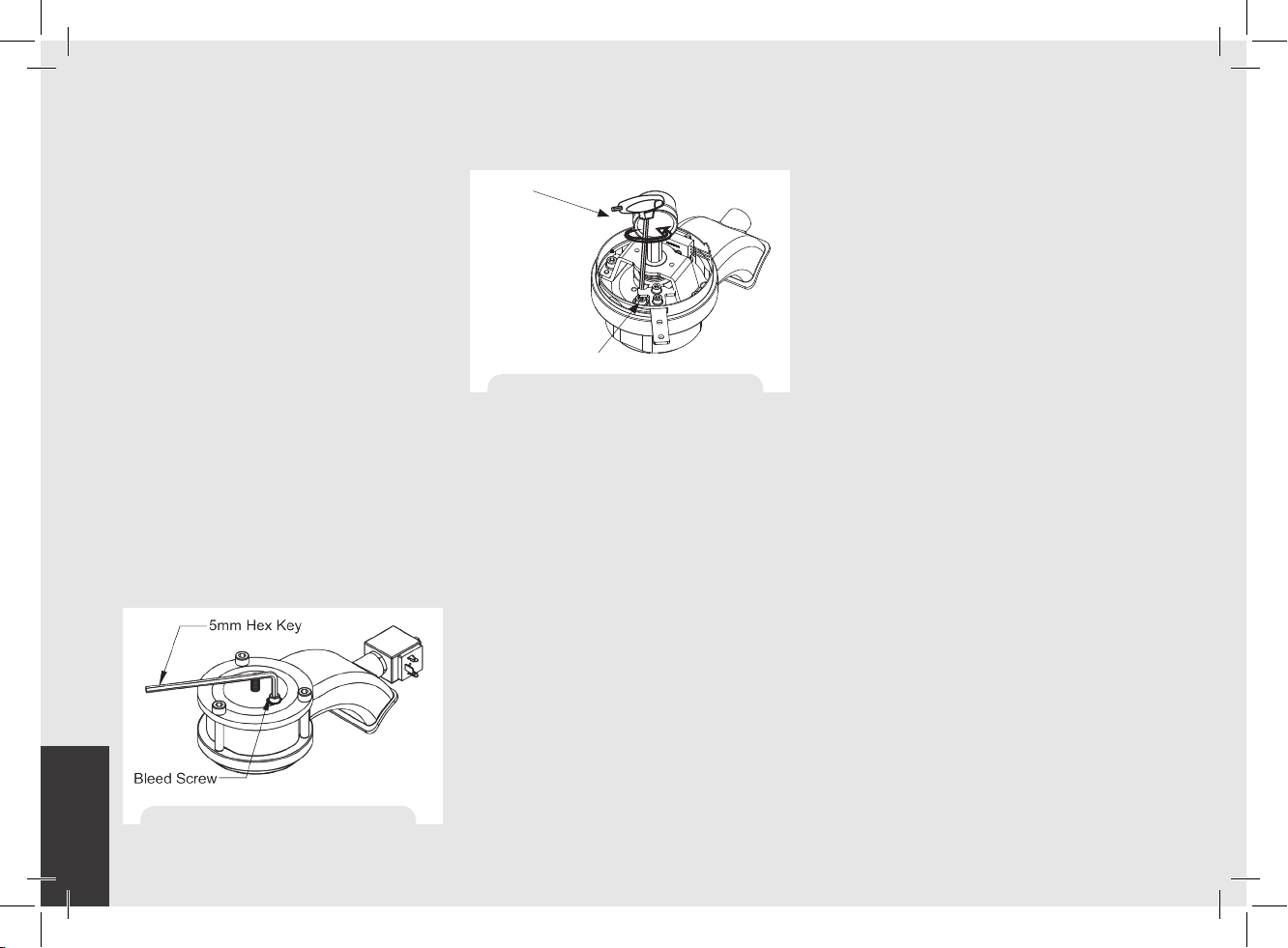
Coffee Boiler: The water ows inside the
coffee boiler directly when the water pump
is activated. When the GS/3 is turned on
the electronics will activate the water
pump to ll both boilers. Since the inow
of water will compress the air in the boiler it
will be necessary to remove or “bleed” the
air from the coffee boiler. All air must be
removed in order to completely “saturate”
the coffee boiler/group assembly. To
remove the air from the boiler (“bleed the
groups”) remove the group cover from the
top of the group head. Then loosen the
bleed screw (see picture) to allow air to
escape until water
Figure 3a - “Bleed the Group AV”
8
5 mm Hex Key
Bleed Screw
Figure 3b - “Bleed the Group MP”
ows from below the screw head. It may
be necessary to activate the brew process
by pressing button #5 (the
continuous button) to force the air out of
the group. Tighten the screw to stop the
water from owing. Over-tightening can
cause damage to the sealing washer and
the group cap. If this sealing washer is
damaged replace washer with one included
in accessory kit. Once all air is removed
from the coffee boiler, reinstall the group
cover. For more detailed instruction please
refer the GS/3 Installation Guide.
NOTE: It may be necessary to re-ll the water
reservoir during this process. Check to see if the
“Water Tank Empty” error message is present on
the display before continuing.
4) Verify lling of Boilers.
The installation is now complete and the
espresso machine should be heating to the
operating temperatures.
Brewing after rst installation
Once the rst installation procedures are
nished, before proceeding with brewing
coffee, hot water and steam, please follow
these steps:
• Engage the portalter by inserting it into
the group head and rotate the handle from
left to right. Once the portalter is inserted
properly, you can press one of the brewing
buttons on the keypad to start the ow of
water through the portalter (AV models)
or rotate the handle from left to right (MP
models). Brew water through the group for
at least two minutes.
• Being careful to avoid burns, turn
on steam wand for at least
one minute.
• Turn on the hot water valve for the time
necessary to allow at least 1 liter of water
to be brewed.
5) Waiting for the Espresso Machine to Heat to
Operating Temperature. During this time, the
pointer of the coffee boiler pressure gauge
may reach as high as 12 bar. This may
happen anytime that the heating element
is in the “on” condition. If the pressure
Page 9
EN
exceeds 12 bar then it will
be necessary to adjust the expansion valve
in such a manner that the pressure never
exceed 12 bar.
In normal operating conditions, the coffee
boiler pressure gauge can read anywhere
from 0-12 bar. When brewing,
the pressure should be set to
approximately 9 bar. When the espresso
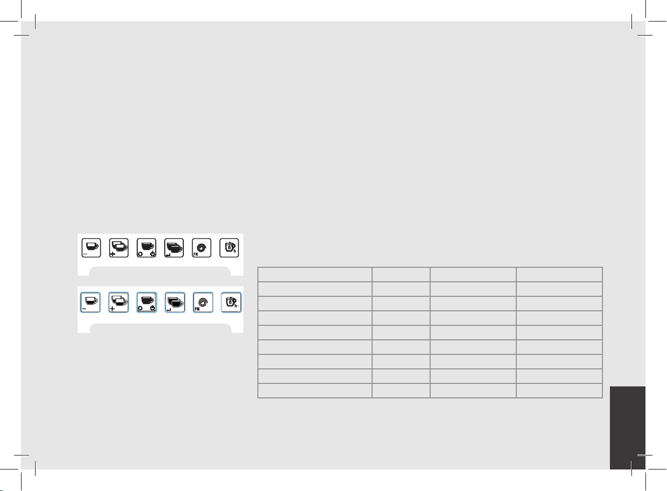
machine is ready to operate all lights on
the keypads will light up.
Figure 4 - Key Pad buttons
Figure 5 - Key Pad buttons with lights on
NOTE: As the steam boiler reaches operating
temperature you may hear air and steam escaping
from the boiler. This is a normal sound. As the water
boils, air in the boiler is replaced by steam and
exits through the vacuum breaker. As the boiler
get closer to operating temperature the vacuum
breaker closes and the steam is no longer able to
escape. This process allows the air in the steam
boiler to escape and to be replaced by water vapor.
Water specications table
Min. Max.
T.D.S. ppm 90 150
Total Hardness ppm 70 100
+2
Total Iron (Fe
Free Chlorine (Cl
Total Chlorine (Cl
pH value 6,5 8,5
Alkalinity ppm 40 80
Chloride (Cl
N.B.: Test water quality (the warranty is void if water parameters are not within the range
specied in the section “installation”)
/Fe+3) ppm 0 0,02
) ppm 0 0,05
2
) ppm 0 0,1
2
–
) ppm not more 50
9
Page 10
EN
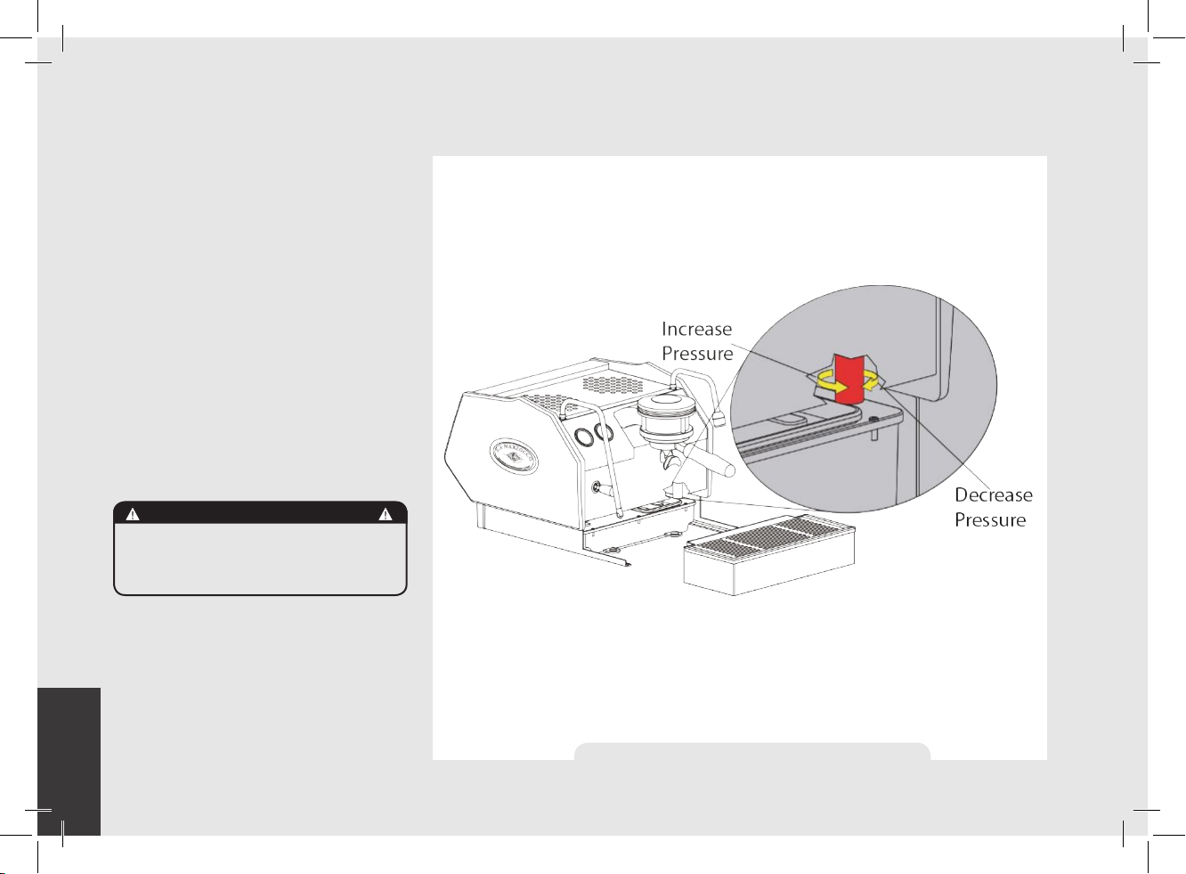
6) Adjusting the Expansion Valve.
The expansion valve is a component
that limits the maximum pressure in the
coffee boiler. Heating the coffee boiler
causes the water within to expand. Since
the coffee boiler is completely saturated,
the expanding water causes an increase
in pressure within the boiler. Without a
safety device the increase in pressure
could cause a rupture in the boiler.
The pressure in the coffee boiler should
never exceed 12 bar. The valve is hot,
so, using adequate protection, rotate the
expansion valve clockwise to increase
pressure. To decrease pressure rotate the
expansion valve counter clockwise (See
the following diagram).
WARNING
THE EXPANSION VALVE CAN DISCHARGE WATER AS
HOT AS 200°F / 93°C. ADEQUATE PROTECTION FOR
HANDLING THIS COMPONENT IS NEEDED BEFORE
ATTEMPTING TO ADJUST.
10
Figure 6 - Expansion Valve Adjustment
Page 11
EN
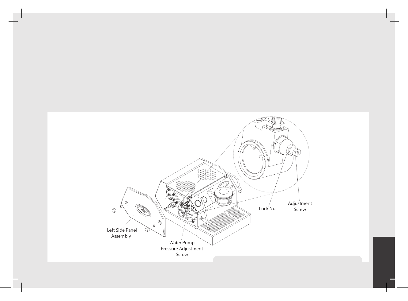
7) Adjusting Water Pump Pressure.
The water pump is factory set at 9 bar
pressure. If it becomes necessary to
change the pressure please use the
following procedure:
1. Remove the left side cover assembly.
2. Locate the water pump adjustment
screw and loosen the lock nut.
3. Adjust the water pump pressure to the
desired measurement.
4. Rotate Clockwise to increase pressure
and counter clockwise to reduce
pressure.
NOTE: The water pump pressure should be
adjusted when the machine is operating
and coffee is present in the portalter.
Figure 7 - Water Pump Pressure Adjustment
11
Page 12
EN
5. Operation
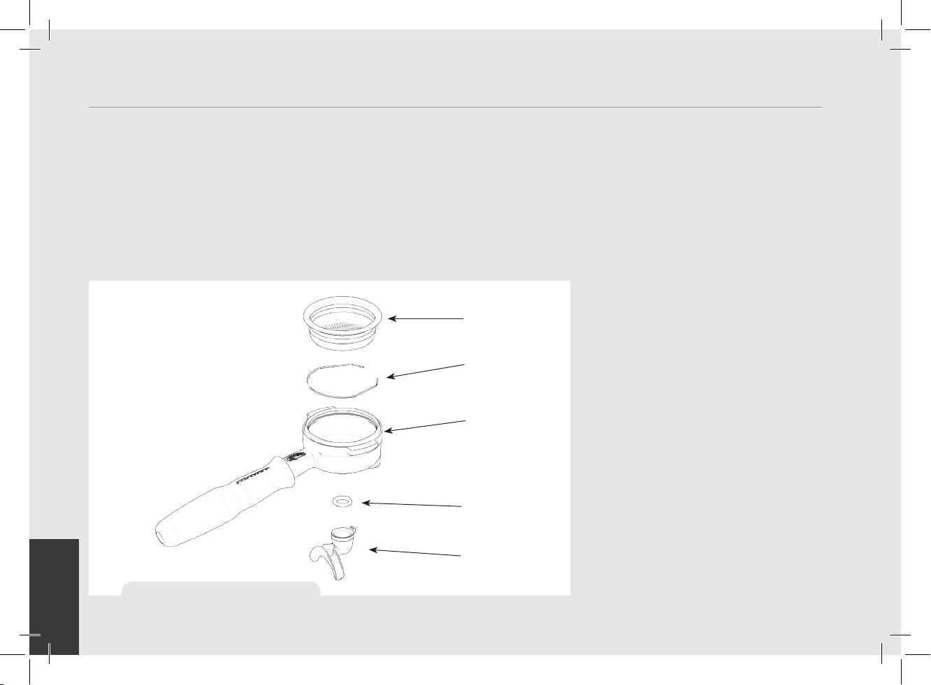
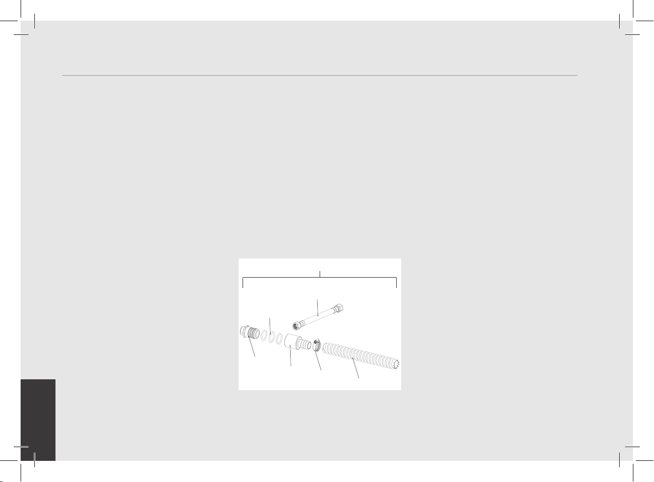
1. Installing the Portalters.
Install the portalter by inserting it into
the group head and rotate the handle
from left to right. Once the portalter is
inserted properly, you can press one of the
brewing buttons on the keypad (AV model)
or move the paddle handle from right to
left (MP Model) to start the ow of water
through the portalter. Please refer to
the Software Programming Manual for a
12
Figure 8 – Portalter
description of the functions of the keypad.
It is important that the portalter is at
operating temperature prior to lling with
coffee. Allow hot water to pass through
the empty portalter for a few seconds
before the brewing process to pre-heat the
portalter.
FILTER
BASKET
SPRING
PORTAFILTER
O-RING
GASKET
DOUBLE
SNAP-ON
SPOUT
Note: It is important to leave the portalter
installed in the espresso machine when
not in use. The portalter must remain
heated for the brewing process to function
correctly.
2. Brewing Coffee. It is now possible to remove
the portalter to make a coffee beverage.
Place some ground coffee in the portalter
basket using the single or double basket.
Press down on the ground coffee with the
supplied tamper and install the portalter
on the GS/3. On AV model press a brew
button to begin the brewing process, or
move the paddle handle from right to left
to begin brewing on MP model (see Fig.2).
NOTE: Some users believe it is important to
allow water to pass through the the group
head prior to installing the portalter
to ush any remaining coffee oils and
particles from the group head. Some
also ush just after brewing for the same
reason. Please experiment to make the
best possible procedure for your coffee.
There are many techniques for brewing
espresso. You can nd instructions for
many techniques on websites, blogs and
forums. Some are even monitored by
professional baristas around the world.
Page 13
EN
3. Dispensing Steam.
In order to allow for any condensed water
in the wand to be released ALWAYS allow
some steam to be discharged by turning on
the valve before inserting the steam wand
into the pitcher of liquid to be heated.
Dip the steam wand into the liquid to be
heated. Depress the steam valve lever to
activate the steaming process.
The steam valve has a variable ow control.
The steam valve will lock in the fully on
position only.
The steam will transfer heat to the liquid
raising its temperature. Be careful not to
allow liquid to overow in order to avoid
severe burns.
In order to prepare milk for making
cappuccino with the right amount of foam,
go through the following steps:
• After purging the steam wand place the
container half-full of milk underneath,
carefully open the steam valve and raise
the container so as to bring the wand end
to a point just below the surface of the
milk; at this point, move the container
up and down just enough to dip the
nozzle end in and out of the milk until
you get the right amount of foam, bring
the temperature of the milk almost up
to 149/158°F or 65/70°C. You can then
pour this milk into a cup containing warm
espresso and you will end up with a fresh
cup of cappuccino.
NOTE: It is important to have a sufcient
volume of liquid in the steaming pitcher.
Therefore if you intend to steam small
amounts of milk it is necessary to use a
small pitcher. If you intend to steam larger
quantities of milk then it is necessary to
use a larger steaming pitcher.
Using too little milk in a steaming pitcher
can allow the milk to be “blown out” of the
pitcher. A good rule to follow is to ll the
steaming pitcher only half full of liquid.
NOTE: In order to prevent the heated liquid
from being sucked back into the steam
boiler it is recommended that you purge
the steam system after heating any liquid.
Purge the system by opening the steam
valve for a few seconds to allow steam to
escape to the atmosphere from the end
of the steam wand. Failure to do so can
cause the heated liquid to transfer from
the steaming pitcher to the steam boiler
(via vacuum created from cooling parts).
This condition is undesireable and can
cause contamination in the steam boiler.
4. Dispensing Hot Water.
You may dispense hot water by using the
hot water nozzle. To dispense hot water
press the hot water button.
Figure 9 - Hot Water Button
This button commands the hot water
delivery. The volume of water delivered
may be adjusted via the display (see the
Software Programming Manual for further
instructions). The temperature of the water
dispensed may be adjusted by adjusting
the mixing valve under the right side cover
of the espresso machine (see machine
description diagram, Figure 2, and the
instructions on the next page).
WARNING
THE COFFEE BOILER AND STEAM BOILER CONTAIN
WATER AT ELEVATED TEMPERATU-RE. WATER
TEMPERATURE OVER 125°F/52°C CAN CAUSE SEVERE
BURNS INSTANTLY OR DEATH FROM SCALDING (COFFEE
BOILER 200°F/93.3°C-STEAM BOILER 260°F /127°C)
WARNING
THIS MACHINE IS NOT SUITABLE FOR OUTDOOR USE.
jETS OF WATER SHOULD NOT BE USED TO CLEAN THE
MACHINE, NOR SHOULD IT BE PLACED WHERE WATER
jETS ARE USED.
13
Page 14
EN
6. Key Features
1. Controlling the Brew Process Using Volumetric
Programming.
This espresso machine allows the
volumetric programming of each of the
rst 4 buttons on each group (numbered
left to right). Please consult the Software
Programming Manual for further
instructions.
2. Hot Water Dispensing.
Hot water may be dispensed from the
Hot Water Wand on the right side of the
machine. This is accomplished by pressing
the hot water button (Fig.9). The amount
of water dispensed can be programmed via
the digital display. Please consult Software
Programming Manual for programming
instructions. The temperature of the hot
water may be adjusted slightly via the
Hot Water Adjusting Knob. This adjusting
knob is hidden under the right side panel
assembly. The knob protrudes slightly
form the bottom of the side panel. To nd
this knob, look at the bottom edge of the
right side panel.
The knob may be turned by sliding a nger
under the side panel from front to rear (to
decrease temperature) or from rear to front
(to increase temperature).
3. Quick Keys.
The GS/3 has 4 Quick Keys to allow the
user to gain quick and easy access to
important parameters that may be changed
frequently. Please see the Software
Programming Manual.
4. Water and Drain Connection Kit.
The GS/3 comes with a main water supply
and waste drain connection kit. This kit
allows the GS/3 to be connected to the
main water supply and the main waste
drain system. Instructions for installing
this kit are contained in the GS/3
Installation Manual. The conversion kit
contains the following items:
913 (CE) / 914 (ETL-USA)
L325 (CE)
L326 (ETL/USA)
H.1.010.01
F.8.002
F.8.003
L312
L308
5. General Notes for Coffee Preparation. The
portalters must remain heated since
they are at the lowest position of the
group itself, and they are partially isolated
from the same due to the rubber gasket
between them. This can be accomplished
by leaving the portalters installed in the
machine when not in use. The portalters
may also be actively heated by activating
one of the brew buttons to ush hot water
through the portalter then turning off the
water ow.
6. Coffee Grind.
The size of the coffee granules is extremely
important in preparing a good cup of
coffee, along with the type of coffee blend
used. The ideal grind can be determined by
making various coffees using the amount
of ground coffee that you would normally
use for each cup (we recommend at least
6g). The best grind is that which allows
coffee to ow out from the portalter
spouts neither too slowly, drop by drop, nor
too quickly. A general rule is that a double
dose should dispense approximately 60mL
/ 2 uid oz. of espresso in approximately
25 seconds. This time may be adjusted by
varing the coarseness of the grind.
14
Page 15
EN
7. IMPORTANT To improve the avor prole
of the espresso, the temperature of the
water in the coffee boiler, and therefore
of the groups, may eventually be raised
or lowered via the digital display (please
consult Software Programming Manual for
detailed instructions).
N.B.
If the machine has not been used for more
than 8 hours or, in any case, after long
periods of being idle, in order to use the
machine to its full potential it is necessary
to perform some cleaning cycles before
brewing beverages as follows:
• Group: with the portalter engaged in
the group brew water through it for at least
two minutes
• Being careful to avoid burns, turn on
each steam wand for at least one minute.
• Turn on the hot water valve for the time
necessary to allow 1 liter of water to be
brewed.
• If using machine with water reservoir,
change the water in the reservoir daily.
If the machine is not going to be used for
long periods of time, it is advisable to
follow these safety indications:
• Disconnect the machine from the water
mains or interrupt the water connection
via a mains tap.
• Disconnect the machine from the
electrical mains.
WARNING
IF THE ABOVE-MENTIONED INSTRUCTIONS ARE NOT
ADHERED TO THE MANUFACTURER CANNOT BE HELD
RESPONSIBLE FOR DAMAGE TO PERSONS OR THINGS.
15
Page 16
EN
7. Preventative Maintenance and Cleaning
Cleaning (Daily)
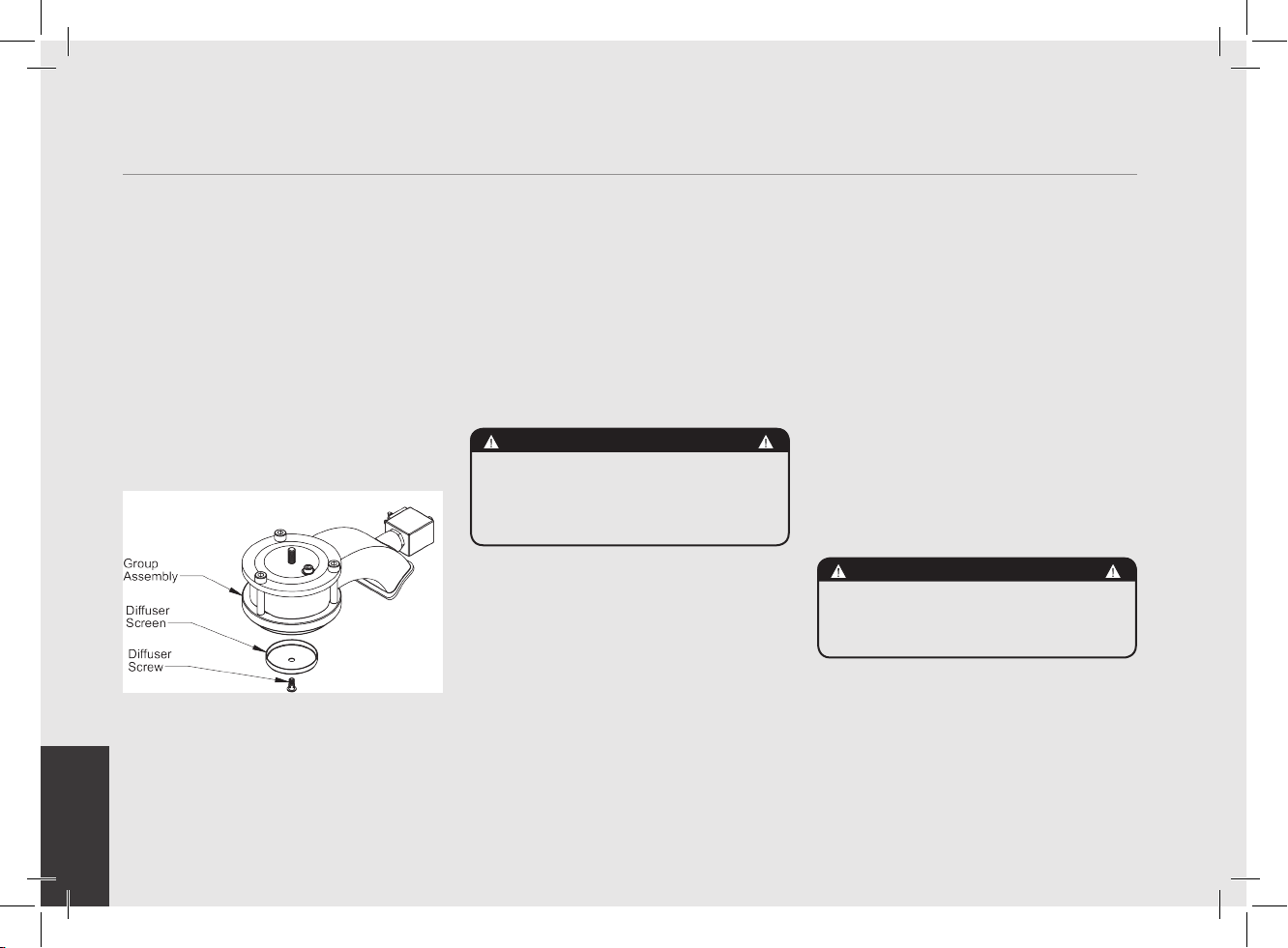
1. Cleaning the Diffuser Screen.
During the discharge operation
(subsequent to coffee brewing), small
amounts of coffee grounds may slowly
build-up on and obstruct, even partially,
the diffuser screen. Turn off the machine
and remove the diffuser screen by
unscrewing the diffuser screw. Soak in
detergent powder liquid following the
instructions of detergent manufacturer.
Rinse thoroughly with clean water. Install
and run hot water through the group head
several times with the screen installed.
2. Cleaning the Brewing System.
Insert the blind lter into portalter
and put the correct amount of espresso
cleaning product (following the product’s
instructions) into the lter, engage the
portalter into the group you want to clean.
• Press the brewing button for said group,
as if you were making a regular cup of
coffee. Stop the water after about 15-20
seconds.
• Start and stop the group several times
until you notice clear water being released
instead of soapy water when you remove
the portalter.
Do not remove the portalter when group
is actually brewing water.
CAUTION
DO NOT REMOVE THE FILTER HOLDER WHILE RELATIVE
GROUP IS BREWING HOT LIQUIDS. THE COFFEE BOILER
CONTAINS WATER AT ELEVATED TEMPERATURE. WATER
TEMPERATURE OVER 125°F / 52°C CAN CAUSE SEVERE
BURNS INSTANTLY OR DEATH FROM SCALDING.
• Rinse the group using a normal lter
in the portalter, by running hot water
through it several times.
3. Cleaning Filter Baskets and Portalters.
With daily cleaning of the stainless steel
lters and portalters it is sufcient
to clean them with water and a cloth or
appropriate brush. Otherwise, using an
espresso cleaning product, following the
product’s instructions put the correct dose
in about 1/2 a litre of water inside a
heat-resistant container and heat.
• If using stainless steel portalters with
snap-on spouts remove the spout.Immerge
lters and metallic parts of portalters
(not handles) in the hot solution and leave
them submerged for about 30 minutes.
• Rinse thoroughly with clean water and
run hot water through the group several
times with the lter and portalter
engaged.
4. Cleaning the Drain Box.
Remove the drain box assembly and wash
each of the components with hot soapy
water. Rinse thoroughly and reinstall the
drain box assembly. Hand wash each part
with water containing mild soap.
CAUTION
THE MACHINE MUST NOT BE DIPPED IN, NOR SPLASHED
WITH, WATER IN ORDER TO CLEAN IT. FOR CLEANING
OPERATIONS, PLEASE FOLLOW THE INSTRUCTIONS
VERY CAREFULLY.
5. Cleaning the Body.
Wipe the stainless steel surfaces with a
soft, non abrasive cloth in the direction of
the glazing marks, if any. Do not use any
alcohol or solvents whatsoever on painted,
imprinted, or plastic parts in order not to
damage them. Clean the side panels using
16
Page 17
EN
a soft cloth. Do not spray the keypad or
display with any liquid. Clean only with a
damp soft cloth.
6. Cleaning the Hot Water and Steam Nozzles.
Steam nozzles must be cleaned
immediately after use with a damp cloth
and by producing a short burst of steam
so as to prevent the formation of deposits
inside the nozzles themselves, which
may alter the avor of other drinks to
be heated. Hot water nozzles must be
cleaned periodically with a damp cloth. If
milk residue is present on the steam wand,
soak the tip in a container of hot water,
then it will be possible to wipe the tip
clean. Repeat process if residue remains.
NOTE: This cleaning schedule is based
upon a moderate to average use (20-
300) cups per day. If machine use is less
than moderate then this schedule may be
adjusted accordingly.
Cleaning (Periodic)
1. Draining Boilers. Both the coffee boiler
and the steam boiler may be drained and
relled to reduce the chance of mineral
deposits build up on the inside walls of the
inside surfaces. Additionally this draining
process can be used to remove water that
has a bad odor or taste.
Drain the Steam Boiler: Turn OFF the machine.
Remove the left side panel assembly.
Locate the ball valve on the bottom left
side of the machine. Hold the ball valve
with one tool and remove the brass cap on
the end of the valve. Move the espresso
machine close to a waste drain and tip
machine at an angle to point the valve into
the waste drain.
Drain the Coffee Boiler: Turn OFF the
machine. Using adequate protection or
an appropriate tool, loosen the expansion
valve until water begins to ow freely. Then
remove the group cap cover and loosen
the bleed screw. When nished draining
empty the drain box assembly.
Steam boiler draining: to activate this function
you need to access the programming menu
(see p. 50).
2. Clean the Water Reservoir.
The water reservoir needs to be cleaned
periodically to ensure that no algae forms
on the inside surfaces. To clean rst remove
the water reservoir form the machine.
Disconnect the clear plastic water intake
hose. Unscrew all screws from the cover
to separate the parts. Wash all parts with
warm soapy water. Hand wash each part
with water containing mild soap.
WARNING
THE EXPANSION VALVE CAN DISCHARGE WATER AS
HOT AS 200°F / 93°C. ADEQUATE PROTECTION FOR
HANDLING THIS COMPONENT IS NEEDED BEFORE
ATTEMPTING TO ADjUST.
Cleaning frequency
Daily
• Portalter
• Filter
• Diffuser screen
• Diffuser screw
• Steam wand (just after use)
• Drain grille
Weekly
• Water Reservoir
• Drain Box
Monthly
• Cleaning the hot water nozzle
17
Page 18

EN
8. Mandatory Maintenance and Check-up Operations
These operations are in addition to the Maintenance and Periodic Cleaning Operations as specied in Chapter 7.
The following maintenance and check-up operations sould be carried out by a qualied technician.
The time required for the periodic maintenance is determinated by the quantity of daily work and/or coffee consumption.
N.B. These periodic maintenance operations are not covered by warranty.
▪ Replace group gaskets
▪ Replace diffuser screens
▪ Clean auto-fill probe
▪ Check vacuum breaker for
proper operation
▪ Inspect water inlet valve
▪ Inspect drain system for leaks
or clogs
▪ Check flow rate for each group
▪ Rebuild steam assemblies
▪ Replace portafilter baskets
▪ Inspect group valve plungers
▪ Inspect vacuum breaker
▪ Inspect steam boiler
pressurestat
▪ Inspect expansion valve
▪ Check brew temperature
▪ Check that brew pressure is
at 9bar
▪ Check all switches for proper
operation
▪ Check/note water hardness
▪ (Water quality must be within
the range of parameters
specified in the chapter
EVERY SIX/EIGHT MONTHS (in addition to the above)
▪ Inspect electrical wiring
condition
▪ Inspect boilers safety switches
▪ Replace over-pressure valve
(safety valve)
▪ Accurate control of the
EVERY THREE/FOUR MONTHS
on Installation, otherwise
warranty is voided)
▪ Check filter basket condition
If AV Model:
▪ Check shot volumes
▪ Test flowmeter’s ohm value
(ohm value is acceptable if
greater than 1.8 K ohm, and
less than 2.2 K ohm
EVERY YEAR (in addition to the above)
tightness at 2,4Nm of
each cable on the terminal
block.
If MP Model:
▪ Disassembly and lubrication
of the components of the MP
valve
▪ Check the condition of the inside of boilers and if necessary rinse out with a proper cleaning product allowed for food and beverage
EVERY 3 YEARS (in addition to the above)
appliances.
18
Page 19

EN
gs3
Installation Guide
Chapters
1. Unpackage GS/3 Espresso Machine
2. Fill with water
(Initial Fill)
3. Drain box alignment
4. Connect to power supply
5. Turn on main power
6. Turn on espresso machine
7. Remove group cover
pag 20
pag 20
pag 21
pag 21
pag 22
pag 22
pag 23
8. Remove air from group head
(bleeding the group)
9. Monitor coffee boiler pressure
10. Adjust the expansion valve
11. Monitor steam boiler pressure
12 . Brew espresso
13. Verify working boiler pressures
14. Connect to main water supply
pag 23
pag 24
pag 25
pag 26
pag 27
pag 27
pag 28
19
Page 20

EN
Installation Guide
Remove/Open the ll cover and ll
the reservoir with ltered water.
2
Slide the reservoir back into
position and replace the drain box. Make
sure the drain box is inserted fully. The
water reservoir must make contact with the
level indicators on the rear side. Failure
to make contact will result in the display
message “Rell Tank”. The message
“Rell Tank” will be displayed anytime the
reservoir does not have contact with the
level indicators.
NOTE: The GS/3 is congured to work with
the water reservoir. To connect the GS/3
to the mains water supply and the waste
drain system, please refer to number 14
on page 24.
20
Unpackage espresso machine and set on a level surface. Ensure all accessories
are included with shipment. See accessories list on page 4 of Owner’s Manual.
1
Check for any visable damage to espresso machine.
WARNING
THE COFFEE MACHINE MUST BE PLACED IN A
HORIZONTALPOSITION ON A COUNTER HIGHER THAN 80
CM FROM THE GROUND
Page 21

EN
Alignment holes
3
Alignment pins and
locking clips
IMPORTANT NOTE:
The drain box must be installed correctly for the machine
to function properly. The drain box has two alignment
pins that mate with two alignment holes on the base of
the GS/3. When installing the drain box, ensure that the
alignment pins are inserted into the alignment holes.
It may be necessary to push slightly on the front of the
drain box to achieve proper alignment. Open the two clips
outwards to lock drain box into place.
Connect the power
cord to power supply
4
capable of supplying:
230 VAC and 10 amps (for
the 230 V version) or 120VAC
and 15 Amps (for the 110 V
version).
THE MACHINE IS INTENDED TO BE PERMANENTLY
WARNING
CONNECTED TO MAINS POWER SUPPLY.
IT IS MANDATORY THAT A RESIDUAL CURRENT DEVICE
(RCD) WITH A RATED RESIDUAL OPERATING CURRENT NOT
EXCEEDING 30 mA IS INSTALLED.
21
Page 22

EN
WARNING
THE MANUFACTURER DECLINES ANY
RESPONSIBILITY FOR ANY EVENT LEADING TO LIABILITY
SUITS WHENEVER GROUNDING HAS NOT BEEN
COMPLETED ACCORDING TO CURRENT LOCAL, NATIONAL,
AND INTERNATIONAL REGULATIONS AND ELECTRICAL
CODES, OR IF OTHER ELECTRICAL PARTS
HAVE BEEN CONNECTED IMPROPERLY.
Turn on power by pressing the main power switch. The
main power switch may be found on the left rear of the
5
machine.
22
Turn on power by pressing the power switch, the 3th button on the
keypad.
6
Page 23

EN
Press the “continuous” button to allow water to enter
7
into the coffee boiler and wait for the brewing phase to end.
Repeat twice. Now it is necessary to remove all of the air in the
coffee boiler to saturate the group. This is commonly referred
to as bleeding the group. To do this, remove the group cover
by rotating the cover counter clockwise (AV models) or remove
the pressure gauge, remove the paddle knob, remove the cover,
replace the pressure gauge and rotate the lever to the left (MP
models).
Unscrew the bleed screw
(approximately 1/2 turn) to release all
8
included 5mm hex key wrench). When water
leaks from under the screw head, tighten the
screw. Note: It might be necessary to activate
the brewing process to force water into the
boiler. To do this, press the continuous
key until water leaks from under the screw
head. Then tighten screw. Replace group
cover removed in previous step. The steam
boiler will begin to ll automatically and
the reservoir will need to be relled. Once
boiler is full, heating phase will begin and
the expansion valve will need to be adjusted
immediately (see next step).
air from the coffee boiler (using the
23
Page 24

EN
Steam Boiler
Pressure Gauge
9
24
Coffee Boiler
Pressure Gauge
Next it will be necessary to check the expansion valve. As the coffee boiler heats to operating temperature the pressure in the
coffee boiler will rise. There is an expansion valve behind the drain tray that allows some water to escape during this process
to limit the maximum pressure in the coffee boiler to 12 bar. Please monitor the coffee boiler pressure gauge during the initial
heating process. You should notice the gauge approach 12 bar and stop. If the pressure gauge does not reach 12 bar or if
the pressure gauge rises above 12 bar, then it will be necessary to adjust the expansion valve. Please follow the next step to
properly adjust the expansion valve.
Page 25

EN
10
Increase pressure
Please follow this procedure if it is necessary to adust the expansion valve.
First remove the drain box to access the expansion valve. The expansion valve
protrudes through the sheet metal, has the shape of a cylinder, is brass in color
and approximately 25mm in diameter. The valve will be hot, so, using adequate
protection, in order to adjust the expansion valve rotate the valve clockwise
to raise the pressure and counter clockwise to reduce the pressure. It may be
necessary to use a tool such as a pair of pliers to rotate the expansion valve in
1/4 turn or less increments until the desired pressure is achieved. Replace the
drain box after each adjustment to ensure the machine is operating correctly.
Decrease pressure
WARNING
THE EXPANSION VALVE CAN DISCHARGE WATER AS
HOT AS 200°F / 93°C. ADEQUATE PROTECTION FOR
HANDLING THIS COMPONENT IS NEEDED BEFORE
ATTEMPTING TO ADjUST.
25
Page 26

EN
You may also monitor the steam boiler heating progress by watching the Steam Boiler Pressure Gauge. The steam boiler is set
at approximately 2.0 Bar of pressure at the factory.
11
Once the pressure gage reaches this point the heating will stop. When the coffee boiler reaches operating temperature all lights
on the keypad will light. Should you wish to adjust the pressure of the steam boiler please refer to the Software Programming
Guide under the section “Steam Boiler temperature”.
Steam Boiler
Pressure Gauge
26
Coffee Boiler
Pressure Gauge
Page 27

EN
When the espresso machine is ready, place ground coffee into the
portalter and activate the brewing process. For additional information
12
to operate this espresso machine please refer the the Owner’s Manual
or the Software Programming Guide.
When brewing, the coffee boiler
pressure should be between 8-10 bar.
The steam boiler pressure should be
set at 2 bar but can operate at any
setting between 1.3 bar and 2 bar.
Steam Boiler
Pressure Gauge
Coffee Boiler
Pressure Gauge
27
Page 28

EN
Water Pump
Left side panel
assembly
913 (CE) / 914 (ETL-USA)
H.1.010.01
F.8.002
F.8.003
Pump Inlet Tube
L325 (CE)
L326 (ETL/USA)
L312
Access Hole
L308
WARNING
WHEN THE MACHINE IS PLUMBED-IN
TO WATER MAINS, ENSURE AT EACH
INSTALLATION A NEW SET OF TUBES FOR
PLUMBING AND RELATED GASKETS IS
USED.
1. Please follow this procedure to connect the GS/3 to
the mains water supply and the waste water drain
system:
2. Turn off the machine and remove the plug from the
socket.
3. Remove the drain box, slide out the water reservoir
from the machine base.
4. Remove the left side panel assembly. Disconnect the
hose from the top of the reservoir and remove the
water reservoir.
5. Remove the drain box cap.
6. Remove the drain box cap and insert the drain box
hose barb tting (F.8.002) Do not over-tighten this
part. Over-tightening will damage the drain box.
7. Connect the clear armoured drain hose to the hose
barb tting and to the waste drain using the supplied
hose clamp.
8. Tighten the supplied hose clamp.
9. Connect the stainless steel braided hose (L325
or L326) to the water pump and pass through the
access hole on the base under the pump. This hose
will connect the pump to the mains water supply.
10. Replace the drain box on the machine base.
11. Reconnect the power plug to the power outlet.
Turn on the water supply and the main power
switch, check for leaks.
12. Congure the “Water Tank” parameter in the software
to “not present” (see the Software Programming
Guide for directions).
13. Turn on the machine.
(These instructions are also available on the website.
http://techcenter.lamarzocco.com.)
28
Page 29

EN
gs3
Software Programming Guide
Programming Introduction
Digital Display
Programming Keypads
Accessing Programming Mode
Start Up Procedures
Shut Down Procedures
Quick Access Programming (Quick Keys)
“Machine OFF” Programming
Language
Name
Heating (Power Mode)
Water Reservoir (Tank)
Tea Water
Steam Boiler Probe Sensitivity
Service Cycles
pag 30
pag 31
pag 32
pag 34
pag 35
pag 36
pag 37
pag 38
pag 39
pag 40
pag 41
pag 42
pag 43
PID Setting
Coffee Boiler Temperature Offset
Water Filter Alarm
Open Valve (modello AV)
Drain Steam Boiler
Safety Valve
First Installation
“Machine ON” Programming
Water Volume Programming (AV models)
Clock Adjust
Auto ON/OFF
Coffee Boiler Temperature
Steam Boiler Temperature
Pre-Infusion or Pre-Brewing (AV models)
Service Phone
Crono Function
pag 46
pag 47
pag 48
pag 49
pag 50
pag 51
pag 52
pag 53
pag 54
pag 55
pag 56
pag 57
pag 58
pag 59
pag 60
Temperature Measurement Units
Proportional, Integral, Derivitive Settings
pag 44
pag 45
Troubleshooting
pag 61
29
Page 30

EN
Programming Introduction
LaMarzocco 09 :30
Firenze Italia
Description
• This espresso machine has a CPU and many congurable settings.
• Additionally, there are many feedback controls employed in this espresso machine to troubleshoot problems should they occur.
• The following is a brief introduction to the controls and display and how they interact with the operator.
Digital Display
The digital display is a backlit display capable of displaying 2 lines of 16 characters. The display enables the operator to interact with
the espresso machine to visibly change parameter values. The display also provides valuable information to the operator.
There are several warnings that the can be displayed to alert the operator of an unusual condition or a fault. Additionally, simple
messages are displayed alerting the operator that an action has been started or that a process needs to begin.
30
Page 31

EN
Programming Keypad (from s/n 0001 to 5378)
The keypad has two functions. The rst is for control of the espresso. The second is for programming individual software parameters.
The button
“Espresso” and “2 Espressos” respectively.
The button
“Coffee”.
The button
The button
The label for this button is “Continuous”.
The button
This keypad has the same functions as the above keys according to the identical symbols in bottom left corner.
and the
is used to access certain parameters and for advancing the cursor within a parameter. The label for this button is
is currently not used in programming mode. The label for this button is “2 Coffees”.
is used to access the programming mode. This button is also used as a function key and to scroll through parameters.
is used to turn on and turn off the espresso machine and to activate the dispensing of the Hot Water.
button are used to change the values of the individual parameters. The label for these buttons are
MP (PADDLE) Programming Keypad (from s/n 0001 to 5418)
_
+ o
31
Page 32

EN
Programming Keypad (only from s/n 5379)
The keypad has two functions. The rst is for control of the espresso. The second is for programming individual software parameters.
The button
“Espresso” and “2 Espressos” respectively.
The button
“Coffee”.
The button
The button
The label for this button is “Continuous”.
The button
and the
is used to access certain parameters and for advancing the cursor within a parameter. The label for this button is
is currently not used in programming mode. The label for this button is “2 Coffees”.
is used to access the programming mode. This button is also used as a function key and to scroll through parameters.
is used to turn on and turn off the espresso machine and to activate the dispensing of the Hot Water.
button are used to change the values of the individual parameters. The label for these buttons are
MP (PADDLE) Programming Keypad (only from s/n 5419)
This keypad has the same functions as the above keys according to the identical symbols in bottom left corner.
32
Page 33

EN
Display Operating Procedure
Description
Accessing Programming Mode
Programming Mode
• To change the values of any parameter
LaMarzocco 9:30
• There are two levels within the
• The two programming levels are as
• Machine “On” - The parameters
200.5oF 09:30
La Marzocco T:00
Doses Sett ing
Select within50s
OFF 09:30
Language
ENGLISH
While the espresso machine is on, press and hold the button . After approximately 5 seconds the fol-
1
lowing display appears.
This is the “Machine On” programming level. To program the dispense volume for each button see “Water
2
Volume Programming”. To access the “Machine On” programming mode press the button
Note: You must scroll, using the
While the espresso machine is off, press and hold the button . After approximately 10 seconds the
1
following display appears.
This is the “Machine Off” programming level. Press the button to scroll through the available parameters.
2
Note: You must scroll to the end to exit programming mode.
the operator must rst enter into the
programming mode.
programming mode that allow the
programming of specic parameters.
follows
Machine On Programming Level
button, to the end to exit programming mode.
Machine Off Programming Level
contained within this level are ones
the operator can change to affect the
quality of the espresso.
• Machine “Off” - The parameters
contained within this level are ones
the operator can change to affect the
performance of the espresso machine.
These parameters are set at the factory
and there is no need for adjustment. La
Marzocco reccomends that no changes
are made at this level.
.
33
Page 34

EN
Display Operating Procedure
Description
Start Up Procedures
Turning the Espresso
Machine On
The following is the procedure for turning
on the power to the espresso machine.
• Please follow the procedures carefully
to avoid any damage to the espresso
machine.
• Continue with the water reservoir full or
a mains water connection.
3D5 DE LUXE MAR
OFF 09:30
170 .5oF 06:30
La Marzocco T:00
34
Turn the Main Switch to the On position.
1
The message at left will be displayed briey. This message indicates the revision level of the software
2
installed in this espresso machine. Then the following message is displayed.
To complete the turn on process, press the button and the display at left is shown. The machine begins
3
to automatically ll the steam boiler until full. When the espresso machine reaches operating temperature,
all keypad lights will light indicating that the espresso machine is ready to use.
NOTE: Ensure all air is removed from the group prior to staring the espresso
machine. This only needs to be completed once during the initial setup or when
Instructions for bleeding the groups of air can be found in the Installation Guide.
water is drained from the coffee boiler.
HAZARDOUS VOLTAGE DISCONNECT FROM POWER SUPPLY BEFORE SERVICING
WARNING
Page 35

EN
Display Operating Procedure
Description
Turning the Espresso
Machine Off
200.5°F 09:30a
La Marzocco T: 00
The following is the procedure for turning
off power to the espresso machine.
• Please follow the procedures carefully
to avoid any damage to the espresso
machine.
Shut Down Procedures
• This machine has two off settings. One
setting turns off all of the components
in the espresso machine and the other
turns off power to the complete espresso
machine.
170.5oF 06:30
La Marzocco T:00
OFF 09:30
The following is the procedure for safely turning off the espresso machine.
1
2
Press and hold the button
This is the OFF setting used in the normal operating conditions.
3
During servicing or other conditions that warrant it, the main switch should be turned to the OFF position.
4
The espresso machine is off and display should be blank. It is important to follow this procedure when
turning off the machine. Failure to do so can damage the electronics.
then press the button
WARNING
HAZARDOUS VOLTAGE DISCONNECT FROM POWER SUPPLY BEFORE SERVICING
. The display changes to the following:
35
Page 36

EN
Display Operating Procedure
Description
Quick Access Programming (Quick Keys)
Quick Keys
• For convenience, there is access to ve
parameters of the software without
entering program mode.
• These parameters are accessed through
the use of “Quick Keys”.
• To use the Quick Keys, press and hold
the function button and then the quick
key is accessed.
• In the current version of the software
Rinsing in
progress
T . Coffee Boiler
200.5 oF
T. Steam Boiler
260.0 oF
Pre Brewi ng
Enabled
OFF 15:45
1
Quick Key 1 Press and hold the button , then press the button .
2
Quick Key 2 Press and hold the button , then press the button .
3
Quick Key 3 Press and hold the button , then press the button .
4
Quick Key 4 Press and hold the button , then press the button .
5
Quick Key 6 Press and hold the button , then press the button .
NOTE: Quick Keys only function when the espresso machine is on and not brewing coffee/hot water.
(ver 1.15) the following quick keys are
available:
Quick Key
Number
1 Group rinse cycle
2 Coffee Boiler Temperature
3 Steam Boiler Temperature
4 Pre-Brewing enable/disable
6 Machine Off function
Function
N.B. MP (PADDLE) MODEL Quick Key no. 1 and no. 4 do not function because the control of the group is manual.
36
Page 37

EN
Display Operating Procedure
Description
Language
Language
English
• This parameter allows the operator to
change the language of the display.
“Machine OFF” Programming
OFF 09:30
Language
ENGLISH
Temperature
°F
Enter into “Machine Off” programming mode.
1
2
Press the button or the button to change the language.
3
When nished, press the button to continue to the next parameter.
37
Page 38

EN
Display Operating Procedure
Description
“Machine OFF” Programming
Name
Name
--------------
• This parameter allows the technician to
• The user name is displayed continuously
• The user name is not displayed when
program a 16 character user name.
on the display on the second line.
the Crono Function is ENABLED.
OFF 09:30
Language
ENGLISH
Name
Name
XXXXXXXXXX
Enter into “Machine Off” programming mode.
1
2
Scroll through the displayed parameters using the button until the following display appears:
3
Press the button or the button to change the value of the ashing parameter.
4
Press the button to advance to the next character. Repeat step 3-4 to program remaining characters
5
When nished, press the button to continue to the next parameter.
38
Page 39

EN
Display Operating Procedure
Description
Heating (Power Mode)
Heating
Half
• This espresso is equipped with a power
saving feature that allows the espresso
machine to operate at lower power if
needed.
• While in power saving mode you
may experience slightly longer steam
recovery time. The steam boiler
pressure/temperature may be adjusted
to compensate for this if needed.
“Machine OFF” Programming
• There are two options in Power saving
mode:
• Full - This mode gives full power to both
the coffee boiler and the steam boiler.
On 120V model, in full power mode, a
20 Amp circuit is required.
• Half - In this mode the power is
alternated between the coffee boiler and
the steam boiler (with priority given to
the coffee boiler).
OFF 09:30
Language
ENGLISH
Heating
Half
Enter into “Machine Off” programming mode.
1
2
Scroll through the displayed parameters using the button until the following display appears:
3
Press the button or the button to change the value between Half and Full.
4
When nished, press the button to continue to the next parameter.
39
Page 40

EN
Display Operating Procedure
Description
“Machine OFF” Programming
Water Reservoir (Tank)
Water Tank
Present
• This parameter allows the user to choose
the use of a water reservoir. If the
espresso machine is connected directly
to the water supply, then this value
should be set to “not present”.This must
be done before the machine is plumbed.
OFF 09:30
Language
ENGLISH
Tank
Present
40
Enter into “Machine Off” programming mode.
1
2
Scroll through the displayed parameters using the button until the following display appears:
3
Press the button or the button to change the value between PRESENT and NOT PRESENT.
4
When nished, press the button to continue to the next parameter.
Page 41

EN
Display Operating Procedure
Description
Tea Water
Tea Water
with Pump
• This parameter allows the technician to
select the activation of the water pump
during hot water dispensing.
• When hot water is drawn from only the
steam boiler this parameter should be
set to “without pump”.
“Machine OFF” Programming
• If you wish to adjust temperature of water
using the Hot Water Adjusting Knob, set
this parameter to “with pump”, see page
11 for more details.
OFF 09:30
Language
ENGLISH
Tea Water
with Pump
Enter into “Machine Off” programming mode.
1
2
Scroll through the displayed parameters using the button until the following display appears:
3
Press the button or the button to change to either WITH PUMP or WITHOUT PUMP.
4
When nished, press the button to continue to the next parameter.
41
Page 42

EN
Display Operating Procedure
Description
“Machine OFF” Programming
Steam Boiler Probe
Sensitivity
ProbeSensitivity
LOW
• This parameter allow the user to set
the probe sensitivity depending of the
hardness of the water. The harder the
water, the lower the sensibility of the
probe.
OFF 09:30
Language
ENGLISH
ProbeSensitivity
Low
42
Enter into “Machine Off” programming mode.
1
2
Scroll through the displayed parameters using the button until the following display appears:
3
Press the button or the button to change the value between LOW, MID and HIGH.
4
When nished, press the button to continue to the next parameter.
Page 43

EN
Display Operating Procedure
Description
Service Cycles
Service Cycles
0
• This parameter allows the user to
program a threshold number of cycles (in
multiples of 1000) when the machine
prompts for service.
• When Prompted for Service, the “Service
Phone” number will be displayed.
“Machine OFF” Programming
OFF 09:30
Language
ENGLISH
Service Cycles
0
Enter into “Machine Off” programming mode.
1
2
Scroll through the displayed parameters using the button until the following display appears:
3
Press the button or the button to change the value (range =99000).
4
When nished, press the button to continue to the next parameter.
N.B. : To reset this parameter once “Service Phone” number is displayed. Turn off machine with on/off
switch behind machine.
Press and hold and buttons. Turn on machine holding the two buttons until “Service Reset”
appears on display.
43
Page 44

EN
Display Operating Procedure
Description
“Machine OFF” Programming
Temperature Measurement Units
Temperature
• This parameter is set at the factory at the
request of the local distributor.
• This parameter has two options Celsius
(°C) or Fahrenheit (°F).
°F
OFF 09:30
Language
ENGLISH
Temperature
°F
Enter into “Machine Off” programming mode.
1
2
Scroll through the displayed parameters using the button until the following display appears:
3
Press the button or the button to change the value to either Celsius (°C) or Fahrenheit (°F).
4
When nished, press the button to continue to the next parameter.
44
Page 45

EN
Display Operating Procedure
Description
Proportional, Integral,
Derivitive (PID) Settings (Coffee
Boiler)
C kP k I k D
8. 0 0.15 10. 0
• This parameter is preset at the factory
based upon theoretical calculations and
physical experiments.
• It is not recommended that these
numbers are changed.
• Changes to these parameters can cause
unexpected results.
• Qualied technicians may wish to
experiment with different values.
“Machine OFF” Programming
• If you do wish to change the values
and nd that unexpected results occur,
return to the factory default values:
kP kI kD
8.0 0.15 10.0
OFF 09:30
Language
ENGLISH
C kP kI kD
8.0 0.15 10.0
Enter into “Machine Off” programming mode.
1
2
Scroll through the displayed parameters using the button until the following display appears:
3
Press the button or the button to change the value of the asing parameter.
4
When nished, press the button to continue to the next parameter.
45
Page 46

EN
Display Operating Procedure
Description
“Machine OFF” Programming
PID Setting
PID Setting
20.1
°F
• This parameter sets a range in which the
PID algorithm is active.
• This parameter is preset at the factory
based upon theoretical calculations and
physical experiments.
• It is not recommended that this number
is changed. Changes to this parameter
can cause unexpected results.
• It is important to write down the number
before any changes are made to make
sure you can return to the factory
programming if unexpected results
occur.
• Experienced technicians may wish to
experiment with different values.
• The lowest value for this parameter is
3.6°F / 2.0°C
OFF 09:30
Language
ENGLISH
PID Setting
20.1
°F
Enter into “Machine Off” programming mode.
1
2
Scroll through the displayed parameters using the button until the following display appears:
3
Press the button or the button to change the value of the parameter.
4
When nished, press the button to continue to the next parameter.
46
Page 47

EN
Display Operating Procedure
Description
Coffee Boiler Temperature
Offset
Coffee T. Offset
1.5
°F
• This parameter isused to calibrate
the coffee boiler temperature system
to ensure the display temperature
accurately represents the temperature of
the water exiting the group head.
• This parameter is preset at the factory
based upon initial tests of this espresso
machine.
“Machine OFF” Programming
• It is not recommended that this number
is changed. Changes to this parameter
can cause unexpected results.
• It is important to write down this value
before making changes to be sure you
can return to the factory programming if
unexpected results occur. Each machine
may have a different value as it is set
individually.
OFF 09:30
Language
ENGLISH
Coff ee T. Offset
1.5
°F
Enter into “Machine Off” programming mode.
1
2
Scroll through the displayed parameters using the button until the following display appears:
3
Press the button or the button to change the value of the asing parameter.
4
When nished, press the button to continue to the next parameter.
47
Page 48

EN
Display Operating Procedure
Description
“Machine OFF” Programming
Water Filter Alarm
Water f ilter
0
• This parameter allows the technician
to preprogram an alarm that noties
the user when the water lter requires
service or replacement.
• When the programmed volume of
water has passed through the espresso
machine the error message “Change
Filter” is displayed.
• A value of 0 (zero) disables the lter
alarm parameter.
OFF 09:30
Language
ENGLISH
Water filter
0
Filter
Alarm
Filter
Reset
Enter into “Machine Off” programming mode.
1
2
Scroll through the displayed parameters using the button until the following display appears:
3
Press the button or the button to change the value of the asing parameter.
4
When nished, press the button to continue to the next parameter.
When the espresso machine has dispensed the value of this parameter the message FILTER ALARM will
5
appear.
NOTE: To reset this message turn off the espresso machine using the main power switch.
Then, press and hold the button
switch.
Hold both buttons until the following message appears. Release both buttons and continue to use the
espresso machine as normal.
and the button and turn on the machine using the main power
48
Page 49

EN
Display Operating Procedure
Description
Open Valve
OPEN VAL VE
DISABLED/ENABLED
• This parameter allows the service staff
to enable/disable the opening of the hot
water valve.
• This parameter allows steam boiler
depressurization.
“Machine OFF” Programming
• This parameter is not available on MP
paddle version.
OFF 09:30
Language
ENGLISH
OPEN VALVE
DISABLED/ENABLED
Enter into “Machine Off” programming mode.
1
2
Scroll through the displayed parameters using the button until the following display appears:
3
Press the button or the button to change the value between DISABLED or ENABLED.
4
When nished, press the button to continue to the next parameter.
49
Page 50

EN
Display Operating Procedure
Description
“Machine OFF” Programming
Drain Steam Boiler
Dra ins SteamBoil
DISABLED/ENABLED
• This parameter enables the technician
to enable/disable the steam boiler
draining.
• This parameter allows the service staff
to renew or “regenerate” the water
contained inside the steam boiler,
discharging about one half of the water
contained in the boiler.
• This procedure is recommended in case
the machine should remain inactive for
more than 8 hours and in any case at
least on a weekly basis.
OFF 09:30
Language
ENGLISH
Drains SteamBoil
DISABLED/ENABLED
Enter into “Machine Off” programming mode.
1
2
Scroll through the displayed parameters using the button until the following display appears:
3
Press the button or the button to change the value between DISABLED or ENABLED.
4
When nished, press the button to continue to the next parameter.
50
Page 51

EN
Display Operating Procedure
Description
Safety Valve
TEST SAFETY VAL V
DISABLED/ENABLED
• This parameter allows the service staff
to enable/disable the safety valve test.
• This parameter allows to bring the
steam boiler temperature to 140°C, thus
triggering the safety valve. Once the
valve has triggered disable the function.
“Machine OFF” Programming
• Should the safety valve fail to trigger
within approximately one minute of the
temperature reaching 140°C, disable
the function and replace the valve.
• Only qualied technicians can perform
this operation.
OFF 09:30
Language
ENGLISH
TEST SAFETY VALV
DISABLED/ENABLED
Enter into “Machine Off” programming mode.
1
2
Scroll through the displayed parameters using the button until the following display appears:
3
Press the button or the button to change the value between DISABLED or ENABLED.
4
When nished, press the button to continue to the next parameter.
51
Page 52

EN
Display Operating Procedure
Description
“Machine OFF” Programming
First Installation
First installat.
DISABLED/ENABLED
• This parameter allows the operator to
reactivate the rst installation message
to the next power of the machine.
NOTE: Ensure all air is removed from the
group prior to staring the espresso
machine.
OFF 09:30
Language
ENGLISH
First installat.
DISABLED/ENABLED
52
Enter into “Machine Off” programming mode.
1
2
Scroll through the displayed parameters using the button until the following display appears:
3
Press the button or the button to change the value between DISABLED or ENABLED.
4
When nished, press the button to continue to the next parameter.
Page 53

EN
Display Operating Procedure
Description
Water Volume Programming
• This parameter allows the operator to
program the water volume (shot volume)
Doses Set ting
se lect withi n 30s
200.5
°F 06:30
La Marzocco T:00
Doses Sett ing
Select within30s
Enter into “Machine On” programming mode.
1
Press one of the following buttons:
2
Water will begin to ow. When the desired amount of water has been dispensed, press the same button
again to Stop the ow of water. The button is now programmed. Repeat this process for subsequent
3
buttons.
for the individual buttons on the keypad.
• The saved program is a number. This
number relates to the number of pulses
the owmeter delivers to the CPU. Once
the programmed number of pulses is
received by the CPU, the ow of water
is stopped.
“Machine ON” Programming
• This parameter is not available on MP
Paddle model as volume is manually
controlled by use of paddle, except for
the last button that controls the dose of
hot water brewed.
53
Page 54

EN
Display Operating Procedure
Description
“Machine ON” Programming
Clock Adjust
• This parameter allows the user to set the
time of day and the day of the week.
• This parameter is used to display time
Clock Adjus t
09:30 Wed 12h
o
200.5
F 06:30
La Marzocco T:00
Enter into “Machine On” programming mode.
1
and is also used by the “Auto On/Off”
parameter
• There are 4 changeable values within
this parameter:
• Hour
• Minute
• Day of week
• Hour Format 12h or 24h
Doses Sett ing
Select within30s
Clock Adj ust
Clock Adj ust
09: 30 thurs 1 2h
54
2
Press and hold the button to enter into programming mode.
3
Then press the button to access the adjustable parameters.
4
Press the button or the button to change the value of the ashing parameter.
5
Press the button to advance to the next value.
6
When nished, press the button to continue to the next parameter.
Page 55

EN
Display Operating Procedure
Description
Auto ON/OFF
• This parameter allows the user to
program the espresso machine to turn on
at a preset time and turn off at a preset
Auto On/Of f
On: --.--
°F 06:30
200.5
La Marzocco T:00
Enter into “Machine On” programming mode.
1
time.
• This feature also allows the espresso
machine to remain in the off condition
for one repeating closed day.
“Machine ON” Programming
Doses Sett ing
Select within30s
Clock Adj ust
Clock Adj ust
09: 30 thurs 1 2h
Auto On/Off
On: -- :--
Auto On/Off
Off: -- :--
Closed On
--------------
2
Press and hold the button to enter into programming mode
3
Then press the button to access the adjustable parameters.
4
Press the button or the button to change the value of the ashing parameter.
5
Press the button to advance to the next value.
6
When nished, press the button to continue to the next parameter.
55
Page 56

EN
Display Operating Procedure
Description
“Machine ON” Programming
Coffee Boiler Temperature
• This parameter is set at the factory at a
preset nominal temperature.
• The temperature of the boiler is
Temp Cof. Boiler
94.6
o
200.5
F 06:30
La Marzocco T:00
Doses Sett ing
Select within30s
Clock Adj ust
Temp Cof. Boiler
94.6
o
C
°C
Enter into “Machine On” programming mode.
1
2
Press and hold the button to enter into programming mode.
3
Then press the button to access the adjustable parameters.
4
Scroll through the displayed parameters using the button until the following display appears:
5
Press the button or the button to change the value of the parameter.
6
When nished, press the button to continue to the next parameter.
measured at the most critical point in
the boiler where temperature uctuation
is the greatest.
• The temperature of the water exiting the
group head is held constant by means
of the mass of the group casting. Even
though the temperature of the boiler
may vary slightly, the temperature of the
water exiting the group is constant.
• To properly calibrate the temperature
of any espresso machine it is import to
measure the temperature of the water
exiting the group by means of an external
temperature measuring device. The
difference of the display temperature
and the measured temperature may be
compansated by use of the “Coffee T.
Offset” parameter.
56
NOTE: It is also possible to change the temperature of the coffee boiler using the “Quick Keys”.
Please see the section entitled “Quick Keys”
DANGER
THE STEAM BOILER CONTAINS WATER AT ELEVATED TEMPERATURES. WATER TEMPERATURE
OVER 125 °F CAN CAUSE SEVERE BURNS INSTANTLY OR DEATH FROM SCALDING.
Page 57

EN
Display Operating Procedure
Description
“Machine ON” Programming
Steam Boiler Temperature
• This parameter is set at the factory at a
preset nominal temperature.
• The temperature of saturated water is
Steam Boiler
T emp 134.0
°F 06:30
200.5
La Marzocco T:00
Doses Sett ing
Select within30s
Clock Adj ust
1
2
3
4
Steam Boiler
Temp 134.0
o
5
C
6
°C
Enter into “Machine On” programming mode.
Press the button to enter into programming mode
Then press the button to access the adjustable parameters.
Scroll through the displayed parameters using the button until the following display appears:
Press the button or the button to change tthe value of the ashing parameter.
When nished, press the button to continue to the next parameter.
NOTE: It is also possible to change the temperature of the steam boiler using the “Quick Keys”. Please see
the section entitled “Quick Keys”
proportional to the pressure inside the
Steam Boiler. Therefore it is possible to
regulate the pressure of the steam boiler
by means of electronic temperature
control. Please use the following tables
as reference when setting the steam
boiler temperature.
• The maximum permitted value for the
temperature setting is 134°C.
Temperature Pressure
247°F/119°C 1.0 bar
260°F/127°C 1.5 bar
272°F/133°C 2.0 bar
CAUTION
The saturation temperature of water will vary
with ambient atmospheric pressure.
Tables in this manual are created for atmospheric
pressure at sea level. Slight adjustment in temperature
will be required for elevations other than sea level.
DANGER
THE STEAM BOILER CONTAINS WATER AT ELEVATED TEMPERATURES. WATER TEMPERATURE
OVER 125 °F CAN CAUSE SEVERE BURNS INSTANTLY OR DEATH FROM SCALDING.
57
Page 58

EN
Display Operating Procedure
Description
“Machine ON” Programming
Pre-Infusion or Pre-Brewing
• This parameter allows the user to enable
or disable the pre-brewing (also called
pre-infusion) function.
PreBrewing
disabled
o
200.5
F 06:30
La Marzocco T:00
Doses Sett ing
Select within30s
Clock Adj ust
PreBrewing
enabled
PreBrew ON sec
Espresso 0.6
Enter into “Machine On” programming mode.
1
2
Press the button to enter into programming mode.
3
Then press the button to access the adjustable parameters.
4
Scroll through the displayed parameters using the button until the following display appears:
5
Press the button or the button to change the value of the parameter.
When enabled, additional parameters are displayed, press the button or the button to change the
6
value.
• When enabled the user is able to
program buttons 1-4. Each button may
have different programming.
• Pre-brewing has two values to adjust for
each button. “ON” time is the amount
of time (in seconds) that the brew valve
is open during during the prebrewing
cycle. “OFF” is the amount of time
(in seconds) that the brew valve is off
during the prebrewing cycle. After
the pre-brewing cycle has completed,
the normal brew cycle continues until
complete.
• This parameter is not available on MP
paddle versione where pre-infusion is
controlled manually by the paddle.
PreBrew OFF sec
Espresso 0.1
58
When nished press the button to continue to the next parameter. Repeat steps 6-7 for all 4 buttons.
A value of zero disables this feature on the corresponding button.
7
NOTE: It is also possible to enable and disable this parameter using the “Quick Keys”. Please see the section
titled “Quick Keys”
Page 59

EN
Display Operating Procedure
Description
Service Phone
• This parameter is a feature that can be
Service Phone
(555)123-4567
°F 06:30
200.5
La Marzocco T:00
Enter into “Machine On” programming mode.
1
• This telephone number will be displayed
when service is required.
used to store the telephone number for a
service company.
“Machine ON” Programming
Doses Sett ing
Select within30s
Clock Adj ust
Service Phone
X
2
Press the button to enter into programming mode
3
Then press the button to access the adjustable parameters.
4
Scroll through the displayed parameters using the button until the following display appears:
5
Press the button or the button to change tthe value of the ashing parameter.
6
Press the button to advance to the next character. Repeat step 5-6 to program remaining characters
7
When nished, press the button to continue to the next parameter.
59
Page 60

EN
Display Operating Procedure
Description
“Machine ON” Programming
Crono Function
• When enabled, this parameter displays a
timer that times each shot.
• The timer is reset each time a button on
Crono Function
the keypad is pressed.
disabled
o
F 06:30
200.5
La Marzocco T:00
Enter into “Machine On” programming mode.
1
• When enabled, the Crono Function is
continuously displayed.
The programmable name will not
be displayed when this parameter is
enabled.
Doses Sett ing
Select within30s
Clock Adj ust
Crono Function
disabled
60
2
Press the button to enter into programming mode.
3
Then press the button to access the adjustable parameters.
4
Scroll through the displayed parameters using the button until the following display appears:
5
Press the button or the button to enable or disable this parameter.
6
When nished press the button to continue to the next parameter.
Page 61

EN
Troubleshooting
• This espresso machine is equipped with several feedback mechanisms that alert the operator when an unusual condition occurs.
Additionally the espresso machine will warn the operator when certain parameters fall below or above the programmed point. These
errors and warnings will appear as a message in the display.
• The following section will describe errors and warnings that may appear in the display.
Description Message SolutionMessage
Corrupted
Data
Fill ing-up T-out
Alarm
T.Probe Unconnect
Boiler temp.
Flowmeter
Alarm
This message is displayed when the CPU does not
understand an instruction.
This message is displayed when the CPU does not
detect a full signal from the steam boiler within a
set time interval.
This message is displayed when the CPU does not
receive any signal from the Safety Probe in the
steam boiler.
This message is displayed when the CPU does not
receive the appropriate signal from the owmeter.
This message is not active in MP machines.
Most likely the machine power was disconnected without rst turning off the machine through the
keypad and display. Turn off machine using main switch. This should clear the error.
When this message is displayed the CPU also shuts down and turns the machine off. Water is not
entering the boiler. Call an authorized service technician to repair this fault.
When this message is displayed the CPU turns off power to the steam boiler heating element. The
only way to reset this error is to repair the Safety Probe to restore the signal to the CPU.
When owmeter alarm is displayed, the light on the button that initiated the brew cycle will begin
to ash. This problem is a result of water not owing through the ow meter. This can be caused
by coffee ground too ne or packed too tightly (try a coarser grind or lighter tamping) or a blockage
in the tubes, a malfunctioning water pump, a faulty valve, or a damaged owmeter. Call a service
technician to x this problem.
61
Page 62

 Loading...