

Page 1
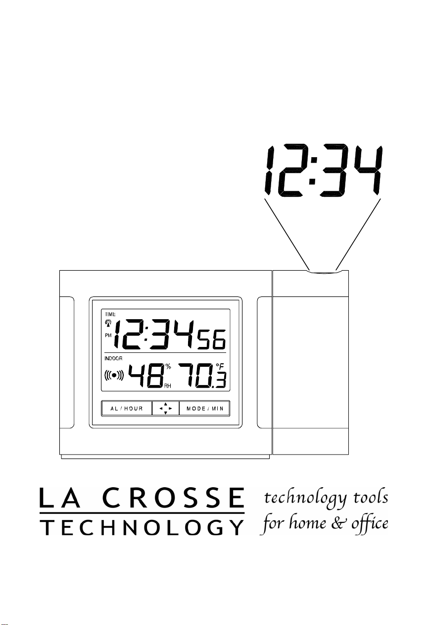
WT-5110
433 MHz
Radio Controlled Projection Alarm
Instruction Manual
Page 2

TABLE OF CONTENTS
Topic Page
Inventory of Contents/ Additional Equipment 3
About WWVB 3
Quick Set-Up Guide 4
Detailed Set-Up Guide
Battery Installation 5
Program Mode
Programming Sequence 6
Function Buttons 6
Manual Time Setting 6
Time Zone Setting 6-7
Daylight Saving Time (DST) Setting 7
Features & Operations
Features 8
Radio-Controlled Time 8
Projection 8
LED Backlight 9
Indoor Temperature 9
Indoor Humidity 9
Time Alarm 9
Changing Display Mode 10
Maintenance & Care 10
Troubleshooting 10
Specifications 11
Warranty and Contact Information 12-13
2
Page 3

INVENTORY OF CONTENTS
ADDITIONAL EQUIPMENT (not included)
FEATURES OF PROJECTION ALARM
Operation of these features is in section III
ABOUT WWVB (Radio Controlled Time)
The NIST (National Institute of Standards and Technology—Time and Frequency Division) WWVB
radio station is located in Ft. Collins, Colorado, and transmits the exact time signal continuously
throughout the United States at 60 kHz. The signal can be received up to 2,000 miles away through
the internal antenna in the projection alarm. However, due to the nature of the Earth’s Ionosphere,
reception is very limited during daylight hours. The projection alarm will search for a signal every
night when reception is best.
The WWVB radio station receives the time data from the NIST Atomic clock in Boulder, Colorado. A
team of atomic physicists is continually measuring every second, of every day, to an accuracy of ten
billionths of a second per day. These physicists have created an international standard, measuring a
second as 9,192,631,770 vibrations of a Cesium-133 atom in a vacuum. For more detail, visit
http://www.boulder.nist.gov/timefreq.htm. To listen to the NIST time, call (303)499-7111. This number
will connect you to an automated time, announced at the top of the minute in “Coordinated Universal
Time”, which is also known as Greenwich Mean Time (GMT). This time does not follow Daylight
Saving Time changes. After the top of the minute, a tone will sound for every second. It is possible
that your projection alarm may not be exactly on the second due to the variance in the quartz.
However, the clock will adjust the quartz timing over the course of several days to be very accurate;
under 0.10 seconds per day.
1) WT-5110 Alarm Clock
2) AC adapter/transformer
3) Instruction manual and warranty card.
1) Two fresh 1.5V AA batteries (optional for projection alarm clock)
1. Radio-controlled time
2. Projection of time
3. LED backlight
4. Display of indoor temperature/humidity or alarm time
5. Time alarm
3
Page 4

QUICK SET-UP GUIDE
Hint: Use good quality Alkaline Batteries and avoid rechargeable batteries.
1. We recommend beginning the set-up procedure at night when the
WWVB signal is easiest to receive.
2. It is also highly recommended to set the projection alarm in a window
or other area free of interference in the area of your home that is
closest to Colorado (the source of the WWVB signal).
NOTE: The above steps are not required but can help the projection
alarm receive the signal faster.
3. Place the batteries into the projection alarm clock.
4. DO NOT PRESS ANY BUTTONS FOR 15 MINUTES.
NOTE: It is important to not press any buttons after inserting batteries as
this will interrupt the WWVB search sequence.
In this time the display will show both the indoor temperature and humidity. If the
station does not display both indoor temperature and indoor humidity after the 15
minutes please retry the set up as stated above. After both indoor temperature
and indoor humidity are displayed for 15 minutes you can place your projection
alarm in your desired location.
To complete the set up of your temperature station after the 15 minutes have
passed please follow the steps beginning on page 6.
4
Page 5
DETAILED SET-UP GUIDE
I.
BATTERY INSTALLATION
A. PROJECTION ALARM
1. Remove the battery cover.
2. Observe the correct polarity, and install 2 AA batteries.
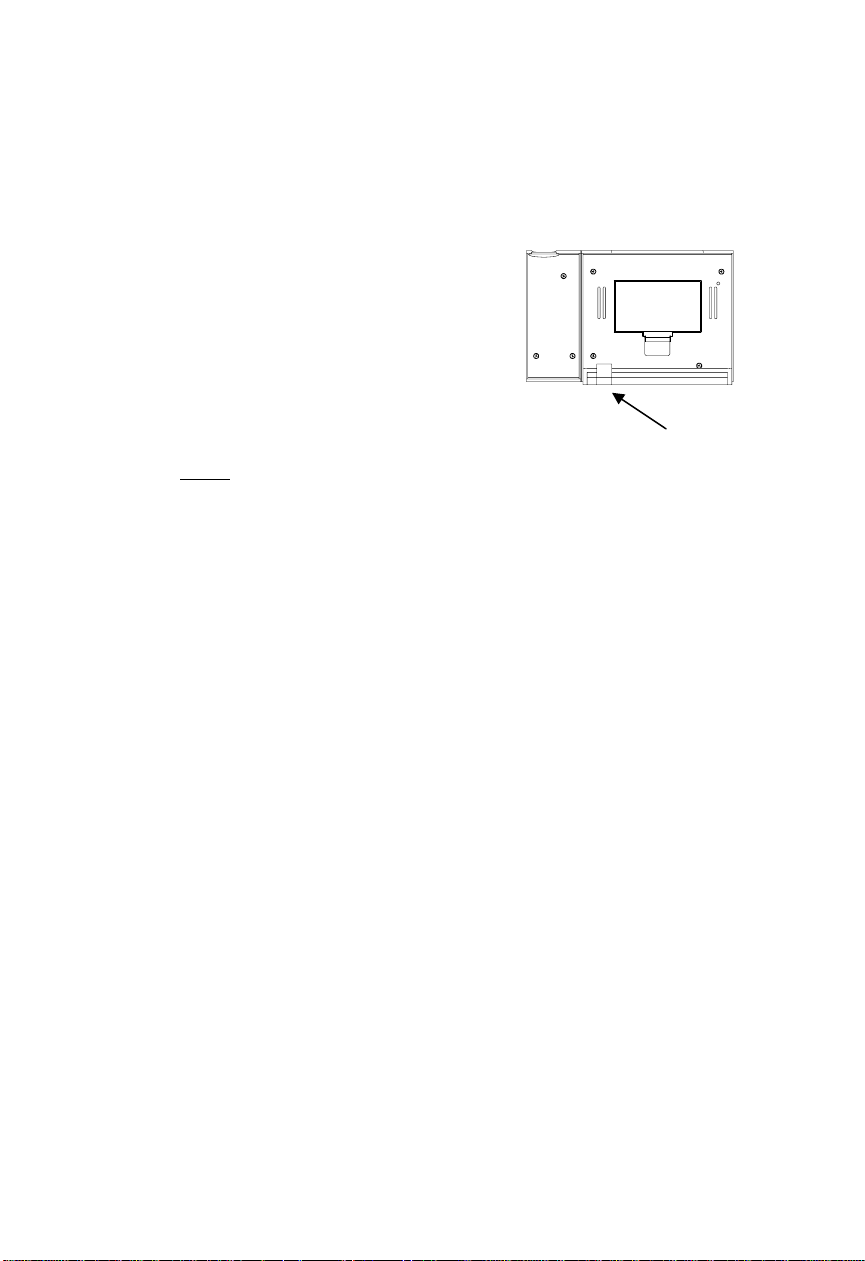
3. In addition or instead of inserting batteries, the AC adapter can be used. Simply plug
the adapter into the receptacle on the
underneath of the alarm clock and then plug
in adapter.
4. Replace the battery cover.
5. The projector will activate and remain on if
the alarm clock is plugged in. If only batteries
are used, the projector will only be activated
when a button is pressed. The projection is a
red light, not harmful under normal usage,
although care should be taken to not look
directly into the light.
Notes:
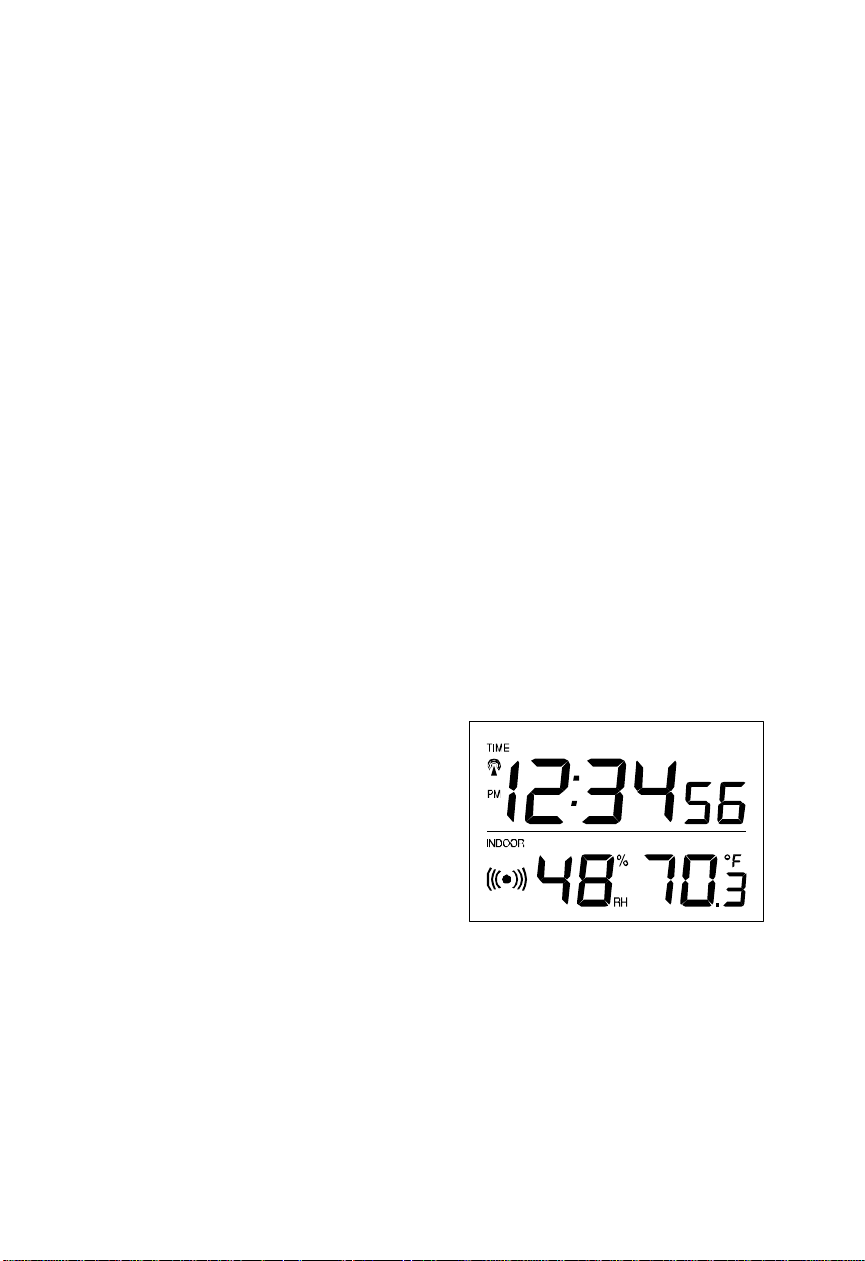
• After the batteries have been installed a tone will sound, and the LCD (Liquid
Crystal Display) will activate.
• The indoor temperature/humidity will be displayed. Also, the time will appear as
“-:--”.
• The WWVB search is automatically initiated, and a tower icon appears and
flashes with the time colon (no tower icon will appear if the WWVB is too weak to
be detected, and the time display will remain on “-:--”).
• While the WWVB search is being conducted various numbers will appear in the
time display.
• After 15 minutes, the projection alarm will either display the WWVB time, or
discontinue the search if the time is not found. If the search is cancelled “-:--” will
remain in the time LCD.
• The projection alarm will conduct a WWVB search every hour until the first signal
is found.
• Once the WWVB time is found, a search is automatically conducted nightly at
midnight.
• If the signal is found at midnight, the tower icon will remain, if not, another search
will take place every hour (until 6:00 am) until the signal is found successfully.
• If no signal is found during this period, the tower icon will not appear and the
clock will search again at 12:00 am the next night.
• The radio-controlled time receiver is located on the bottom side of the projection
alarm. When using the AC adaptor be sure to keep the adapter cord away from
the bottom side of the unit as if the wire is too close it can cause weakened
reception sensitivity.
AC adapter
receptacle
5
Page 6
PROGRAM MODE
)
II.
To enter the Program Mode hold down the “MODE/MIN” button for 3 seconds, until the time
flashes in the top of the display. The Program Mode Guide is laid out in a manner that allows
you to program each function separately, or you can follow the instructions entirely to program
the projection alarm. Complete programming is usually done for the initial set-up, and will
require you to skip step 1 and 2 of programming sections D and E. To exit the setting mode
simply wait approximately 10 seconds for the projection alarm to automatically return to normal
operation.
A. PROGRAMMING SEQUENCE
1. Manual Time Display
2. Time Zone Setting
3. Daylight Saving Time On/Off
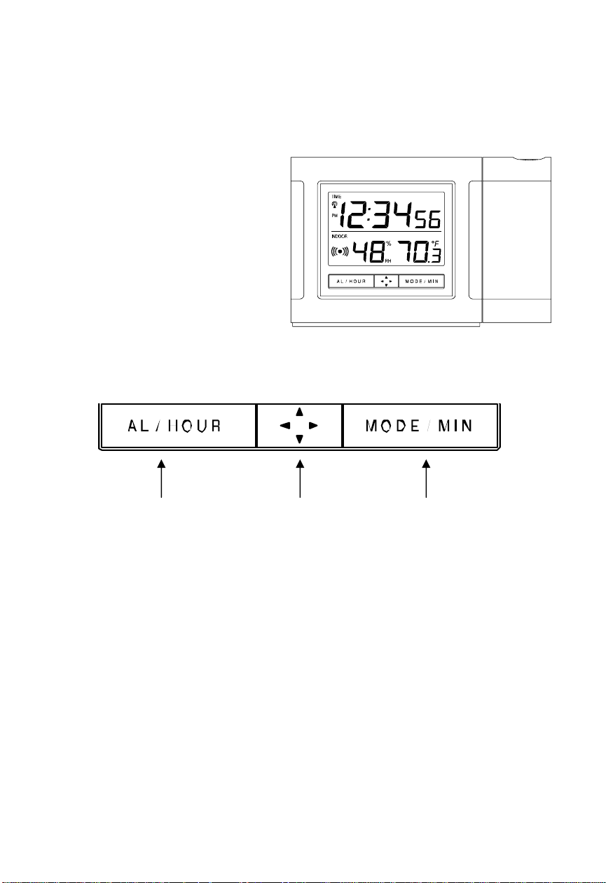
B. FUNCTION BUTTONS
There are 3 function buttons located on the front of the projection alarm and one on the top.
The function buttons are labeled: AL/HOUR, light direction icon, MODE/MIN, and SNOOZE
(the top bar).
Alarm Button (also adjusts
the hours in time setting
C. MANUAL TIME SETTING
D. TIME ZONE SETTING
mode
1. Hold down the “MODE/MIN” button for 3 seconds, the time will flash in the Time LCD.
2. Press and release the “AL/HOUR” button to advance the hours and press and release
the “MODE/MIN” button to advance the minutes.
NOTE: “A.M.” or “P.M.” will be displayed to the left of the time to help identify the time.
3. Press and release the “SNOOZE” button to confirm the time setting and to advance to
DST (Daylight Saving Time) setting.
1. Hold down the “MODE/MIN ” button for 3 seconds, the time will flash in the Time LCD.
2. Press and release the “SNOOZE” button to advance to the time zone selection.
3. In the indoor temperature/humidity section of the LCD the time zone will flash.
Display Direction
6
Mode Button (toggles between
indoor temp/hum and alarm
time. Also adjusts minutes in
time setting mode
Page 7

4. Press and release the “MODE/MIN” button to select the appropriate time zone. There
are 24 time zones to choose from (based relative to the international time standard of
E. DST (DAYLIGHT SAVING TIME) SETTING
GMT (“Greenwich Mean Time).
NOTE: The U.S. time zones will show abbreviations as opposed to the numerical time
zone indicator. For example Eastern Time will display “ET” when the Eastern Time
Zone is selected
5. Press and release the “SET” button to confirm the time zone setting and to advance to
the DST (Daylight Saving Time) setting.
-4h Atlantic Time
-5h Eastern Time (default setting)
-6h Central Time
-7h Mountain Time
-8h Pacific Time
-9h Alaskan Time
-10h Hawaiian Time
-11h, -12h Next two time zones West of HAW
0h Greenwich Mean Time
-1h, -2h, -3h Three time zones West of GMT
The DST default is “On”, meaning that the WWVB will automatically change the time
Note:
according to Daylight Saving Time in the spring and fall. For areas that do not recognize
DST changes (Arizona and parts of Indiana) turn the DST “OFF”.
1. Hold down the “MODE/MIN ” button for 3 seconds, the time will flash in the Time LCD.
2. Press and release the “SNOOZE” button twice to advance to the DST setting.
3. “DST” will appear in the indoor temperature/humidity LCD and “ON” or “OFF” will flash
in the time LCD.
4. Press and release the “MODE/MIN” button to toggle between DST ON and OFF..
5. Press and release the “SNOOZE” button to confirm the DST setting and complete the
set-up sequence.
7
Page 8

FEATURES & OPERATIONS
III.
A. FEATURES
1. Radio-controlled time
2. Projection of time
3. LED backlight
4. Display of indoor temperature/humidity or alarm time
5. Time alarm
B. RADIO-CONTROLLED TIME
C. PROJECTION OF TIME
1. The projection alarm will automatically search for the time signal upon initial set-up
and every night.
2. When the signal is being received, there will be a “tower” icon flashing to the left of the
time display.
3. When the time signal has been received successfully, the tower icon will remain
steady until midnight.
4. The NIST (National Institute of Standards and Technology—Time and Frequency
Division) WWVB radio station is located in Ft. Collins, Colorado, and transmits the
exact time signal continuously throughout the United States at 60 kHz. The signal can
be received up to 2,000 miles away through the internal antenna in the projection
alarm.
5. Due to the nature of the Earth’s Ionosphere, reception is very limited during daylight
hours. The projection alarm will search for a signal every night when reception is best.
6. The WWVB radio station receives the time data from the NIST Atomic clock in
Boulder, Colorado. A team of atomic physicists is continually measuring every
second, of every day, to an accuracy of ten billionths of a second per day. These
physicists have created an international standard, measuring a second as
9,192,631,770 vibrations of a Cesium-133 atom in a vacuum.
7. For more detail, visit http://www.boulder.nist.gov/timefreq.htm. To listen to the NIST
time, call (303) 499-7111. This number will connect you to an automated time,
announced at the top of the minute in “Coordinated Universal Time”, which is also
known as Greenwich Mean Time (GMT). This time does not follow Daylight Saving
Time changes. After the top of the minute, a tone will sound for every second.
8. It is possible that your projection alarm may not be exactly
variance in the quartz. However, the clock will adjust the quartz timing over the course
of several days to be very accurate; under 0.10 seconds per day.
1. When plugged into an AC outlet, the projection alarm can continuously project the
time.
2. When operating on batteries alone, the projection alarm will only project when the
snooze button is pressed or the alarm is sounding.
3. The projection will auto-focus for display from three to six feet away. A dark
surrounding will be necessary to clearly see the projection.
4. The direction of the display can also be rotated 360° in 90° increments by pressing the
directional button. There is no display on the LCD that signifies the direction.
5. The projector case can be rotated 180° to further help orient the projected display.
on the second due to the
8
Page 9
D. LED BACKLIGHT
1. The projection alarm has an LED backlight designed for night-viewing. This will light
up for 4 seconds whenever the snooze button is pressed.
2. The LED backlight cannot be turned on constantly; this would drain the batteries.
E. INDOOR TEMPERATURE
F. INDOOR HUMIDITY
G. TIME ALARM
1. The projection alarm measures indoor temperature with an internal sensor.
2. This temperature is displayed in °F.
3. The indoor temperature will take time to adjust to the surrounding temperature as the
sensor is inside the case.
4. If the remote temperature is placed next to the projection alarm, more often than not
the temperature will not be exact with one another. This is not a defect, but simply
reflects the difference in measuring methods. The remote temperature is designed for
changing temperature at a wide range.
1. The projection alarm measures indoor humidity with an internal sensor.
2. This humidity is displayed as a percentage (%).
3. The indoor humidity will take time to adjust to the surrounding humidity as the sensor
is inside the case.
1. SETTING THE ALARM
a. Press and hold “AL/HOUR” button for three seconds until the alarm time is
flashing.
b. Press and release “AL/HOUR” to advance the hour, and “MODE/MIN” to
advance the minute. The time will display “PM” if set to PM, and nothing if set to
AM.
c. The projection alarm will revert to normal operation when no buttons are pressed
for 15 seconds. The alarm is now set and activated.
2. ACTIVATING/DEACTIVATING THE
ALARM
a. After entering the alarm setting
mode, the alarm is activated.
b. To toggle between activating
and deactivating the alarm,
press the “AL/HOUR” button
briefly. “(((○)))”will be displayed
above the time display when the
alarm is activated.
3. TURNING ALARM OFF (WHILE
SOUNDING)
a. While the alarm is sounding, press and release the “SNOOZE” bar to disable the
alarm for 10 minutes.
b. After the SNOOZE bar is pressed the alarm icon will flash.
c. To disable the alarm for 24 hours, press and release any button other than
SNOOZE or display direction buttons.
NOTE: The alarm will sound for 84 seconds if the “SNOOZE” button is not pressed.
The alarm speeds up twice, once after 20 seconds and again after 50 seconds.
9
Page 10

H. CHANGING DISPLAY MODE (INDOOR TEMPERATURE/HUMIDITY OR ALARM TIME)
There are two possible display modes in the indoor temperature/humidity section of the LCD
(lower left); indoor temperature and humidity or alarm time. To change the display press and
release the “MODE/MIN” button to toggle between the two modes.
MAINTENANCE & CARE
IV.
A. Extreme temperatures, vibrations, and shock should be avoided to prevent damage to the
units.
B. Clean displays and units with a soft, damp cloth. Do not use solvents or scouring agents—
they may mark and damage the displays and casings.
C. Do not submerge in water.
D. Immediately remove all low powered batteries to avoid leakage and damage.
E. Replace with new batteries only, and of recommended size.
F. Opening the casings invalidates the warranty. Do not try to repair the units. Contact
TROUBLESHOOTING
Note:
found at the end of this instructional manual.
La Crosse Technology for Repairs.
Problem: The Projection is faint
Solution:
Problem: The LCD is faint.
Solution: Replace the batteries.
Problem: “OFL” appears in the indoor temperature LCD.
Solution:
Problem: No reception of WWVB signal.
Solution:
Problem: Hour is incorrect (minute is correct).
Solution: Be sure correct time zone and daylight saving time are selected.
Problem: “--.-” appears in outdoor temperature LCD
Solution:
For any questions not answered, contact La Crosse Technology with the contact information
1) Change intensity setting
2) Use AC adapter
3) Darken surroundings
4) Use fresh batteries (if AC is not used)
1) Move unit to an area with warmer or cooler surrounding
temperature.
2) Current surrounding temperatures are outside measuring range.
1) It may help reception to face the front of the projection alarm in the
general direction of Ft. Collins, Colorado.
2) Wait overnight for signal.
3) Be sure the projection alarm is at least 6 feet from any electrical
devices, i.e. TV sets, computers, or other radio controlled clocks.
4) Remove batteries for five minutes, reinsert and leave the unit alone
overnight without pressing buttons.
5) If problems persist contact La Crosse Technology.
1) Check batteries in remote
2) If batteries are replaced in remote, the unit must be re-started.
Remove all batteries, and then follow start up procedure.
10
Page 11

SPECIFICATIONS FOR WT-5110
Temperature:
Measuring range:
Checking intervals: Every 10 seconds
Humidity
Measuring range: 1 – 99%
Checking intervals: Every 10 seconds
Power source:
AC Adapter (included) Input: 120VAC/60Hz Output: DC 6V/100MA
Battery type: 2 x AA, 1.5V (Alkaline recommended) (optional)
14°F to 99°F with 0.2°F resolution
Battery life:
Dimensions (H x W x D):
Projection Alarm Clock
Approximately 12 months, depending on projection
and backlight use
3.5 x 5.5 x 2 in
(90.6 x 140.3 x 48.5 mm)
11
Page 12

WARRANTY INFORMATION
La Crosse Technology, Ltd provides a 1-year limited warranty on this product against
manufacturing defects in materials and workmanship.
This limited warranty begins on the original date of purchase, is valid only on products
purchased and used in North America and only to the original purchaser of this product.
To receive warranty service, the purchaser must contact La Crosse Technology, Ltd for
problem determination and service procedures. Warranty service can only be performed
by a La Crosse Technology, Ltd authorized service center. The original dated bill of sale
must be presented upon request as proof of purchase to La Crosse Technology, Ltd or La
Crosse Technology, Ltd’s authorized service center.
La Crosse Technology, Ltd will repair or replace this product, at our option and at no
charge as stipulated herein, with new or reconditioned parts or products if found to be
defective during the limited warranty period specified above. All replaced parts and
products become the property of La Crosse Technology, Ltd and must be returned to La
Crosse Technology, Ltd. Replacement parts and products assume the remaining original
warranty, or ninety (90) days, whichever is longer. La Crosse Technology, Ltd will pay all
expenses for labor and materials for all repairs covered by this warranty. If necessary
repairs are not covered by this warranty, or if a product is examined which is not in need
or repair, you will be charged for the repairs or examination. The owner must pay any
shipping charges incurred in getting your La Crosse Technology, Ltd product to a La
Crosse Technology, Ltd authorized service center. La Crosse Technology, Ltd will pay
ground return shipping charges to the owner of the product to a USA address only.
Your La Crosse Technology, Ltd warranty covers all defects in material and workmanship
with the following specified exceptions: (1) damage caused by accident, unreasonable use
or neglect (including the lack of reasonable and necessary maintenance); (2) damage
occurring during shipment (claims must be presented to the carrier); (3) damage to, or
deterioration of, any accessory or decorative surface; (4) damage resulting from failure to
follow instructions contained in your owner’s manual; (5) damage resulting from the
performance of repairs or alterations by someone other than an authorized La Crosse
Technology, Ltd authorized service center; (6) units used for other than home use (7)
applications and uses that this product was not intended or (8) the products inability to
receive a signal due to any source of interference.. This warranty covers only actual
defects within the product itself, and does not cover the cost of installation or removal from
a fixed installation, normal set-up or adjustments, claims based on misrepresentation by
the seller or performance variations resulting from installation-related circumstances.
LA CROSSE TECHNOLOGY, LTD WILL NOT ASSUME LIABILITY FOR INCIDENTAL,
CONSEQUENTIAL, PUNITIVE, OR OTHER SIMILAR DAMAGES ASSOCIATED WITH
THE OPERATION OR MALFUNCTION OF THIS PRODUCT. THIS PRODUCT IS NOT
TO BE USED FOR MEDICAL PURPOSES OR FOR PUBLIC INFORMATION. THIS
PRODUCT IS NOT A TOY. KEEP OUT OF CHILDREN’S REACH.
This warranty gives you specific legal rights. You may also have other rights specific to
your State. Some States do no allow the exclusion of consequential or incidental
damages therefore the above exclusion of limitation may not apply to you.
12
Page 13

For warranty work, technical support, or information contact:
La Crosse Technology, Ltd
2809 Losey Blvd. S.
La Crosse, WI 54601
Phone: 608.782.1610
Fax: 608.796.1020
e-mail:
support@lacrossetechnology.com
(warranty work)
sales@lacrossetechnology.com
(information on other products)
web:
www.lacrossetechnology.com
FCC DISCLAIMER
This device complies with part 15 of the FCC rules. Operation is subject to the following two
conditions: (1) this device may not cause harmful interference, and (2) this device must accept any
interference received, including interference that may cause undesired operation.
La Crosse Technology
Made in China
WT-5110
FCC ID: OMO-01RX (Receiver),
THIS DEVICE COMPLIES WITH PART 15 OF THE FCC RULES. OPERATION IS SUBJECT TO
THE FOLLOWING TWO CONDITIONS:
1. THIS DEVICE MAY NOT CAUSE HARMFUL INTERFERENCE, AND
2. THIS DEVICE MUST ACCEPT INTERFERENCE RECEIVED, INCLUDING INTERFERENCE
THAT MAY CAUSE UNDESIRED OPERATION.
13
Page 14

WS-9117U
Wireless 433 MHz
Temperature Station
Instruction Manual
1
Page 15

TABLE OF CONTENTS
Topic Page
Inventory of Contents 3
Quick Setup 4-8
Detailed Setup Guide
Battery Installation 9-11
Setting the Time 11-12
Selecting Units of
Measurement
Features
Minimum and Maximum
Temperatures
Resetting Minimum and
Maximum Temperatures
Additional remote
temperature sensors
(optional)
Mounting 17-18
Troubleshooting 19-20
Maintenance and Care 21
Specifications 22-23
Warranty Information 24-28
12-13
13
13-14
14-16
2
Page 16

INVENTORY OF CONTENTS
1.
The indoor temperature station (Figure
1)
2.
The remote temperature sensor (TX6U)
and mounting bracket. (Figure 2)
3.
3 each, 1/2” Philips screws.
4.
One strip of double sided adhesive tape.
5.
Instruction Manual and Warranty Card.
Figure 1
ADDITIONAL EQUIPMENT
(not included)
1.
1 Philips screwdriver.
2.
2 Fresh AAA 1.5V batteries.
3.
2 Fresh AA 1.5V batteries.
Figure 2
3
Page 17

QUICK SETUP
Hint: Use good quality Alkaline
Batteries and avoid rechargeable
batteries.
1. Have the indoor
temperature station and
remote temperature sensor
3 to 5 feet apart.
2. Batteries should be out of
both units for 10 minutes.
3. Place the batteries into the
remote temperature
sensor first then into the
indoor temperature station.
(All remote temperature sensors must be
started before the indoor temperature
station)
4. DO NOT PRESS ANY
BUTTONS FOR 15
MINUTES.
4
Page 18

In this time the indoor temperature
station and remote temperature sensor
will start to talk to each other and the
display will show both the indoor
temperature and an outdoor temperature.
If the indoor temperature station does
not display both temperatures after the
10 minutes please retry the set up as
stated above. After both indoor and
outdoor temperatures are displayed for
15 minutes you can place your remote
temperature sensor outdoors and set
your time.
The remote temperature sensor should
be placed in a dry, shaded area. The
remote temperature sensor has a range
of 80 feet. Any walls that the signal
will have to pass through will reduce
distance. An outdoor wall or window
will have up to 20 feet of resistance and
an interior wall will have up to 10 feet
5
Page 19

of resistance. Your distance plus
resistance should not exceed 80 ft. in a
straight line.
NOTE: Fog and mist will not harm
your remote temperature sensor but
direct rain must be avoided.
To complete the set up of your indoor
temperature station after the 15 minutes
have passed please follow the steps
below.
1. Press and hold the “SET/CH”
button for 5 seconds.
Note: A “12h” or “24h” will appear
to the left of the time. (“12h” for
AM/PM, “24h” for military time)
a. To change between “12h”
and “24h” press and
release the “MIN/MAX”
button.
6
Page 20

b. When you have your
choice shown on the
display press and release
the “SET/CH” button
once.
2. Degree Fahrenheit will now show.
a. To change between
Fahrenheit and Celsius,
press and release the
“MIN/MAX” button.
b. When you have your
choice shown on the
display press and release
the “SET/CH” button
once.
3. An hour will now be flashing.
a. Press and release the
“MIN/MAX” button until
the correct hour is shown.
Note: When in the 12h mode
there is “PM” displayed under
7
Page 21

the word TIME when in the
PM hours. During the AM
hours this area will be blank.
b. When the correct hour is
shown, press and release
the “SET/CH” button
once.
4. A minute will now be flashing.
a. Press and release the
“MIN/MAX” button until
the correct minutes are
displayed.
Press and release the “SET/CH”
button once more and you are done.
8
Page 22

DETAILED SETUP GUIDE
I.
BATTERY INSTALLATION
A.
REMOTE TEMPERATURE
SENSOR
1.
Remove the mounting bracket.
2.
Remove battery cover
3.
Observing the correct polarity, install
2 AA batteries—make sure they do not
spring free, or start-up problems may
occur. Replace cover.
9
Page 23

B.
INDOOR TEMPERATURE
STATION
Note:
After the batteries are installed, DO
NOT press any buttons. This may interfere
with the signals, causing temperatures to
register incorrectly.
1.
Remove the battery cover on the
backside.
2.
Observing
the correct
polarity,
install 2 AAA
batteries.
3.
Replace
battery cover.
4.
Wait 15
minutes
before
pressing any buttons.
10
Page 24

5.
The indoor temperature station should
now show: “-:- -” in the
TIME LCD, and
temperatures in the
INDOOR and
OUTDOOR LCD’s.
II.
TIME
A.
SETTING THE TIME
1.
Press and hold
the “SET/CH”
button for 5
second, “12h”
will appear in
the TIME LCD.
2.
Press and release the “MIN/MAX”
button to select either 12h time
(am/pm) or 24h time
3.
Press and release the “SET/CH”
button 2 times, the hour will flash in
the upper left corner.
4.
Press and release the “MIN/MAX”
button to set the hours
11
Page 25

Press and release the “SET/CH”
5.
button to move to the minute setting
6.
Press and release the “MIN/MAX”
button to set the minutes.
7.
Press and release the “SET/CH”
button to activate the clock.
Note: When in 12h mode, there is only a
“PM” display, which appears under “TIME.”
If there is no display here it is AM. Make
sure you set the time accordingly.
III.
UNITS OF TEMPERATURE
MEASURE
A.
SELECTING UNITS OF
MEASUREMENT
1.
Press and hold the “SET/CH” button
for 5 second until “12h” or “24h”
appears in the TIME LCD.
2.
Press and release the “SET/CH”
button again, “°F” will appear in the
TIME LCD.
12
Page 26

Press and release the “MIN/MAX”
3.
button to shift between °F and °C.
4.
Press and release the “SET/CH”
button twice to activate settings.
IV.
FEATURES
A.
MINIMUM AND MAXIMUM
TEMPERATURES
1.
Press and release the “MIN/MAX”
button, “MIN” appears in the
temperature LCD’s and the recorded
minimum temperatures are displayed.
2.
Press and release the “MIN/MAX”
button to toggle to the maximum
temperatures. The time of occurrence
of the value for outdoor temperature
will also flash.
B.
RESETTING THE MINIMUM AND
MAXIMUM TEMPERATURES
1.
To reset both the minimum and
maximum temperatures—press and
hold the “RESET/+” button for 4
13
Page 27

seconds.
C. ADDING ADDITIONAL
REMOTE TEMPERATURE
SENSORS (OPTIONAL)
1.
The WS-9117U is able to receive
signals from 3 different remote
temperature sensors. Following are
some brief instructions for the basic
set-up of remote temperature sensor
units with the WS-9117U. These extra
sensors can be purchased through the
same dealer as this unit, or by
contacting La Crosse Technology
directly. A TX6 will monitor
temperature only, a TX3U will
monitor temperature and display the
temperature on its LCD, and the
TX3UP will monitor the temperature
via a probe for use in pools, spas, etc.
Note: When setting up multiple units it
is important to remove the batteries
from all existing units in operation,
then to insert batteries first into all the
14
Page 28

remote temperature sensor units, and in
numeric sequence. Second, install
batteries into the indoor temperature
station. Transmission problems will
arise if this is not done correctly and if
the total time for set-up exceeds 6
minutes.
2.
It is necessary to remove the batteries
from all units currently in operation.
3.
Remove the battery covers to all
remote temperature sensor units.
4.
Place all remote temperature sensor
units in a numeric sequential order.
5.
In sequential order, install batteries
(follow the same battery installation
procedures seen in section “I” of the
Detailed Set-Up Guide).
6.
Install batteries into the indoor
temperature station.
7.
Follow the Detailed Set-Up Guide for
programming and operating
instructions.
15
Page 29

D.
VIEWING AND OPERATING
WITH MULTIPLE REMOTE
TEMPERATURE SENSOR UNITS
1.
To view the temperature of a different
remote temperature sensor unit, press
and release the “SET/CH” button. A
shift from one “boxed” number to the
next should be observed in the
OUTDOOR LCD.
2.
To view the Minimum/Maximum
temperature: first select from which
remote temperature sensor to read data
(indicated by the “boxed” number).
Pressing and releasing the
“MIN/MAX” button will toggle
through the minimum and maximum
indoor temperature, and the minimum
and maximum outdoor temperature.
3.
To reset the Minimum/Maximum
readings, press and hold the
“MIN/MAX” button for four seconds.
16
Page 30

V.
MOUNTING
Note: To achieve a true temperature
reading, avoid mounting in direct sunlight.
We recommend that you mount the remote
temperature sensor on an outside Northfacing wall. The sending range is 80ft;
obstacles such as walls, concrete, and large
metal objects will reduce the range. Place
both units in their desired location before
permanently mounting.
A.
REMOTE TEMPERATURE
SENSOR
1.
Remove the mounting bracket from
the remote temperature sensor
2.
Mount using either screws or
adhesive tape.
3.
Reattach the remote temperature
sensor to the mounting bracket.
B.
THE TEMPERATURE STATION
1.
The indoor temperature station comes
with the table stand already mounted.
If you wish to use the table-stand, all
17
Page 31

that is required is to place the indoor
temperature station in an appropriate
location.
2.
To wall mount, remove the table
stand. To do this, pull down on the
stand from the rear and rotate forward.
a)
Fix a screw (not included) into the
desired wall, and place the indoor
temperature station onto the screw
using the hanging hole on the
backside. Gently pull the indoor
temperature station down to lock the
screw into place.
18
Page 32

TROUBLESHOOTING
NOTE: For problems not solved, please
contact La Crosse Technology via e-mail or
phone, or visit our website,
www.lacrossetechnology.com
Problem: The LCD is faint
Solution: Replace batteries
Problem: No outdoor temperature is
displayed.
Solution:
1) Remove all batteries, reinsert into remote
temperature sensor first, and then into the
indoor temperature station.
2) Place remote temperature sensor closer to
the indoor temperature station.
3) Be sure all batteries are fresh.
4) Place remote temperature sensor and
indoor temperature station in position so
the straight-line signal is not passing
through more than two or three walls.
19
Page 33

Problem: Temperatures do not match if
units are placed next to each other.
Solution: Each temperature sensor is
manufactured to be accurate to within 1
degree plus or minus and under normal
conditions; so two temperature sensors could
be as much as 2 degrees different. However,
the difference can be exaggerated further
because the temperature sensors are
designed for different working
environments. The indoor sensor is less
responsive to ambient air currents because of
the shielding effect of the display's case. In
addition, the case can act as a heat sink to
absorb and store heat from external sources
(i.e. handling of the case or radiant heat). In
addition, the much greater range of the
outdoor temperature sensor requires a
different calibration curve than the indoor
range. Error is usually greater at the extreme
ends of a range, making it harder to compare
different ranges with different curves. Under
non-laboratory conditions, it is difficult to
compensate for the above factors and obtain
an accurate comparison.
20
Page 34

MAINTENANCE AND CARE
INSTRUCTIONS
• Extreme temperatures, vibration, and
shock should be avoided to prevent
damage to the units.
• Clean displays and units with a soft,
damp cloth. Do not use solvents or
scouring agents; they may mark the
displays and casings.
• Do not submerge in water.
• Do not subject the units to unnecessary
heat or cold by placing them in the
oven or freezer.
• Opening the casings invalidates the
warranty. Do not try to repair the unit.
Contact La Crosse Technology for
repairs.
21
Page 35

SPECIFICATIONS
Transmitting
Frequency
Measuring Temperatures
Indoor
Temperature
Station: Indoor
Indoor
Temperature
Station: Outdoor
Temp accuracy
Transmitting
range
Temperature check
Indoor Every 10 seconds
Outdoor Two times in 10 minutes
Batteries—(Alkaline recommended)
Remote
Temperature
Sensor
Indoor 2 x AAA, 1.5V
433MHz
32°F to 140°F with 0.2°F
resolution.
(0°C to 69.0°C with
0.1°C resolution)
-21.8 °F to 156.2°F with
0.2°F resolution.
(-29.9°C to 69.0°C with
0.1°C resolution)
+/- 1°F (+/- .5°C)
Maximum 80 feet (25m)
open space
2 x AA, 1.5V
22
Page 36

Temperature
Station
Dimensions: (H x W x D)
Indoor
Temperature
Station
Remote
Temperature
Sensor
Battery life Approximately 1 year
WARRANTY INFORMATION
La Crosse Technology, Ltd provides a 1-year limited
warranty on this product against manufacturing
defects in materials and workmanship.
This limited warranty begins on the original date of
purchase, is valid only on products purchased and
used in North America and only to the original
purchaser of this product. To receive warranty
service, the purchaser must contact La Crosse
Technology, Ltd for problem determination and
service procedures. Warranty service can only be
performed by a La Crosse Technology, Ltd
authorized service center. The original dated bill of
sale must be presented upon request as proof of
5 x 2.25 x 1 in
(excluding table stand)
(125 x 58 x 23 mm)
5 x 1.5 x 1 in
(128 x 40 x 23 mm)
23
Page 37

purchase to La Crosse Technology, Ltd or La
Crosse Technology, Ltd’s authorized service center.
La Crosse Technology, Ltd will repair or replace this
product, at our option and at no charge as stipulated
herein, with new or reconditioned parts or products if
found to be defective during the limited warranty
period specified above. All replaced parts and
products become the property of La Crosse
Technology, Ltd and must be returned to La Crosse
Technology, Ltd. Replacement parts and products
assume the remaining original warranty, or ninety
(90) days, whichever is longer. La Crosse
Technology, Ltd will pay all expenses for labor and
materials for all repairs covered by this warranty. If
necessary repairs are not covered by this warranty,
or if a product is examined which is not in need or
repair, you will be charged for the repairs or
examination. The owner must pay any shipping
charges incurred in getting your La Crosse
Technology, Ltd product to a La Crosse Technology,
Ltd authorized service center. La Crosse
Technology, Ltd will pay ground return shipping
charges to the owner of the product to a USA
address only.
Your La Crosse Technology, Ltd warranty covers all
defects in material and workmanship with the
following specified exceptions: (1) damage caused
by accident, unreasonable use or neglect (including
the lack of reasonable and necessary maintenance);
(2) damage occurring during shipment (claims must
24
Page 38

be presented to the carrier); (3) damage to, or
deterioration of, any accessory or decorative
surface; (4) damage resulting from failure to follow
instructions contained in your owner’s manual; (5)
damage resulting from the performance of repairs or
alterations by someone other than an authorized La
Crosse Technology, Ltd authorized service center;
(6) units used for other than home use (7)
applications and uses that this product was not
intended or (8) the products inability to receive a
signal due to any source of interference.. This
warranty covers only actual defects within the
product itself, and does not cover the cost of
installation or removal from a fixed installation,
normal set-up or adjustments, claims based on
misrepresentation by the seller or performance
variations resulting from installation-related
circumstances.
LA CROSSE TECHNOLOGY, LTD WILL NOT
ASSUME LIABILITY FOR INCIDENTAL,
CONSEQUENTIAL, PUNITIVE, OR OTHER
SIMILAR DAMAGES ASSOCIATED WITH THE
OPERATION OR MALFUNCTION OF THIS
PRODUCT. THIS PRODUCT IS NOT TO BE USED
FOR MEDICAL PURPOSES OR FOR PUBLIC
INFORMATION. THIS PRODUCT IS NOT A TOY.
KEEP OUT OF CHILDREN’S REACH.
This warranty gives you specific legal rights. You
may also have other rights specific to your State.
Some States do no allow the exclusion of
25
Page 39

consequential or incidental damages therefore the
above exclusion of limitation may not apply to you.
For warranty work, technical support, or information
contact:
La Crosse Technology
2809 Losey Blvd. S.
La Crosse, WI 54601
Phone: 608.782.1610
Fax: 608.796.1020
e-mail:
support@lacrossetechnology.com
(warranty work)
sales@lacrossetechnology.com
(information on other products)
web:
www.lacrossetechnology.com
FCC DISCLAIMER
This device complies with part 15 of the FCC rules.
Operation is subject to the following two conditions: (1)
this device may not cause harmful interference, and (2)
this device must accept any interference received,
including interference that may cause undesired
operation.
26
Page 40

THIS DEVICE COMPLIES WITH PART 15 OF
THE FCC RULES. OPERATION IS SUBJECT TO
THE FOLLOWING TWO CONDITIONS:
1. THIS DEVICE MAY NOT CAUSE HARMFUL
INTERFERENCE, AND
2. THIS DEVICE MUST ACCEPT INTERFERENCE
RECEIVED, INCLUDING INTERFERENCE THAT
MAY CAUSE UNDESIRED OPERATION.
Freq. 433.92 MHz
La Crosse Technology
Made in China
WS-9117U
FCC ID: OMO-01RX (Receiver),
OMO-01TX (sensor)
27
 Loading...