

Page 1

WIRELESS 868 MHz WEATHER STATION
INTRODUCTION:
Congratulations on purchasing this Weather station with wireless 868MHz transmission. It not
only displays the indoor temperature and humdity but also receives the outdoor temperature. It is
further acting as a DCF-77 radio controlled clock. With the totally 15 differe nt weather forecast
icons featured by "weather man", users can easil y observe the forecast weather condition and
will no longer worry the sudden weather change. This innovative product is ideal for use in the
home or office.
« Instant Transmission+» is the up and coming state-of-the-art new wireless
transmission technology, exclusively designed and developed by LA CROSSE
TECHNOLOGY.
“IT +” offers you an immediate update of all your outdoor data measured from the
transmitters: follow your climatic variations in real-time!
Instruction Manual
1
Page 2
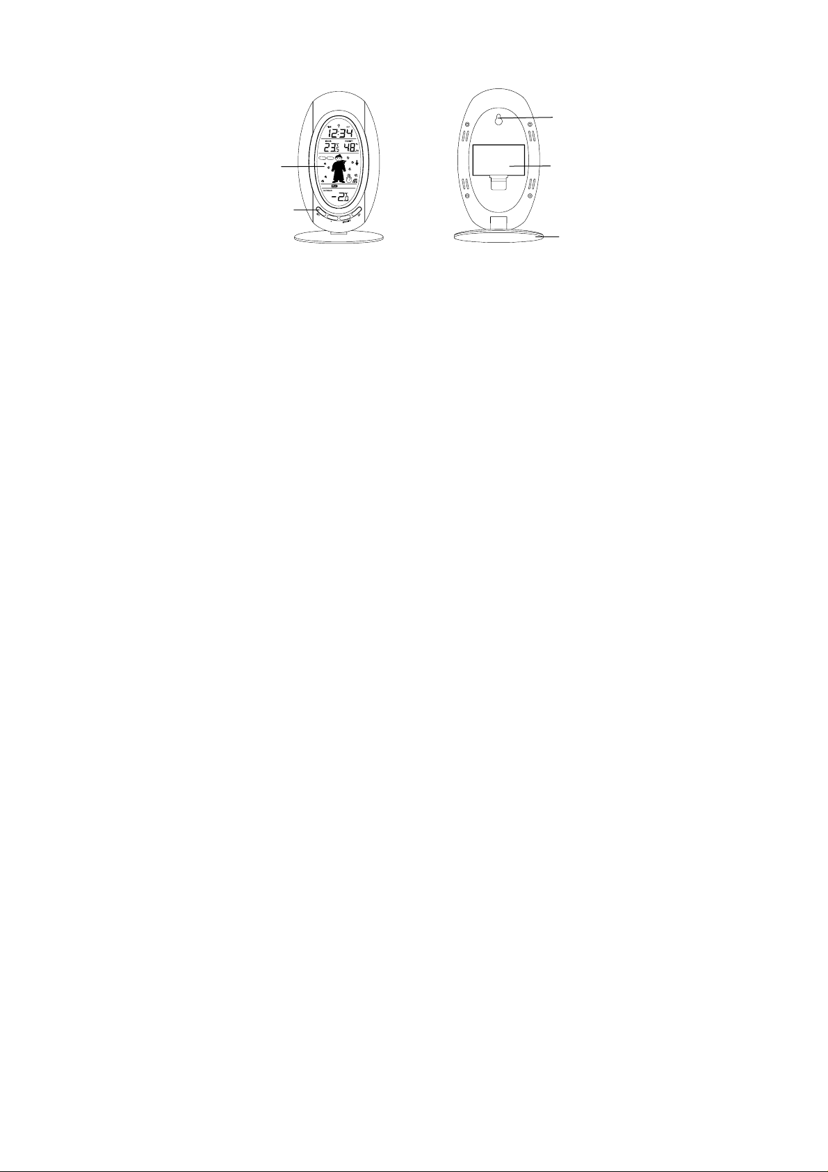
FEATURES:
The Weather station
LCD
Display
Function
2
Keys
Hanging hole
Battery
compartment
cover
Foldout
Stand
Page 3

• DCF Radio controlled time function or manual time setting options
• DCF time reception ON/OFF setting
• 12/24 hour display
• Hour and minute display
• Time zone option ±12 hours
• Wireless transmission at 868 MHz
• Signal reception intervals at 4-second
• Display indoor and outdoor temperature and indoor humidity (% RH)
• Temperature display in degrees Celsius (°C) or Fahrenheit (°F) selectable
• Weather forecasting with 15 easy-to-read weather forecast signs featured by
Weatherman
• Weather forecasting icon sensitivity setting
• Indoor and Outdoor temperature display with MIN/MAX recording
• All MIN/MAX temperature records show date and time received
• All MIN/MAX recordings can be reset
• Can take up to three outdoor transmitters
• LCD contrast setting
• Low battery indicator
• Table standing/ Wall mounting
3
Page 4

The Outdoor Temperature Transmitter
SETTING UP:
When one transmitter is used
1. First, insert the b atteries into the Temperature transmitter. (see “Install and replace
batteries in the Temperature transmitter“).
2. Immediately after and within 25 seconds, insert the batteri es into Weather station (see
“Install and replace batteries in the Weather station”). Once the batteries are in
place, all segments of the LCD will light up briefly. Following the time as 0:00 and the
"weather man" icon will be displayed. If these are not displayed after 60 seconds,
remove the batteries and wait for at least 10 seconds before reinserting them.
4
• Remote transmission of outdoor temperature to Weather Station
by 868 MHz
• Shower proof casing
• Wall mounting case (Mounting at a sheltered place. Avoid direct
rain and sunshine)
Page 5

3. After inserting the batteries, the Weather station will start receiving data from the
transmitter. The outdoor temperature and the signal reception icon should then be
displayed on the Weather station. If this does not happen aft er 3 minutes, the batteries
will need to be removed from both units and reset from step 1.
4. In order to ensur e sufficient 868 MHz transmission however, this should under good
conditions be a distance no more than 100 meters betwee n the final position of the
Weather Station and the transmitter (see notes on “Mounting” and “868 MHz
Reception”).
When more than one transmitter is used
1. User shall remove all the batteries from the weather station and transmitters and wait for
60 seconds if setting has been done with one transmitter before.
2. Insert the batteries to the first transmitter.
3. Within 25 seconds of powering up the first transmitter, insert the batteries to the Weather
Station. Once the batteries are in place, all segments of th e LCD will light up briefly.
Following time as 0:00 and the weather man icon will be displayed. If they are not shown
in LCD after 60 seconds, remove the batteries and wait for at least 60 seconds before
reinserting them.
4. The outdoor temperature from the first tra nsmitter (channel 1) should the n be displayed on
the Weather station. Also, the signal reception icon will be displayed. If this does not
happen after 2 minutes, the batteries will need to be removed from both units an d reset
from step 1.
5
Page 6

5. Insert the batteries to the second transmitter as soon as the outdoor temperature rea dings
from the first transmitter are displayed on the Weather station.
Note: User shall insert the batteries into the second transmitter within 25 secon ds of reception
of the first transmitter.
6. The outdoor temperature from the second transmitter and the "channel 2 " icon should
then be displayed on the Weather station. If this does n ot happen after 2 minute, the
batteries will need to be removed from all the units and reset from step 1.
7. Insert the batteries t o the third transmitter as soon as the "channel 2" ico n and outdoor
data are displayed on the Weather station. Then within 2 minutes, the channel 3 outdoor
data from the third transmitter will be displayed and the channel icon will shift back to "1"
once the third transmitter is successfully received. If this is not happen, user shal l restart
the setting up from step 1.
Note: User shall insert the batteries into the third transmitter within 25 seconds of reception of
the second transmitter.
8. In order to ensur e sufficient 868 MHz transmission however, this should under good
conditions be a distance no more than 100 meters betwee n the final position of the
Weather Station and the transmitter (see notes on “Mounting” and “868 MHz
Reception”).
6
Page 7

IMPORTANT:
Transmission problems will arise if the setting for additional sensors is not followed as described
above. Should transmission problems occur, it is necessary to remove the batteries from all units
and start again the set-up from step 1.
9. Once the remote temperature has been received and displayed on the W eather station,
the DCF time (radio controlled time) code reception is aut omatically started. This takes
typically between 3-5 minutes in good conditions.
If after 10 minutes, the DCF time has not been received, pres s the SET key to m anually enter a
time initially.
Note:
Daily DCF reception is done at 02:00 and 03:00 ever y day. If the reception at 03:00 is not
successful, then at 04:00 and 05:00 and 06:00 there are ot her tries, u ntil on e is s uc cessful. I f the
reception at 06:00 is still not successful, then the next try takes place at 02:00 next day.
If reception is successful, the received time will override the manually set time. The dat e is also
updated with the received time. (Please refer also to notes on “DCF Recepti on” and “Manual
Time Setting”)
7
Page 8

BATTERY INSTALLATION
INSTALL AND REPLACE BATTERIES IN THE WEATHER STATION
The Weather station uses 2 x AA, IEC LR6, 1. 5V batteries. To install a nd replace the batteries,
please follow the steps below:
INSTALL AND REPLACE BATTERIES IN THE TEMPERATURE TRANSMITTER
The Temperature Transmitter uses 2 x AA, IEC LR6, 1.5V battery. To insta ll and replace the
batteries, please follow the steps below:
8
1. Remove the cover at the back of the weather station.
2. Insert batteries observing the correct polarity (see
marking).
3. Replace compartment cover.
Page 9

1. Pull out the battery holder at the bottom of the transmitter.
2. Insert the batteries, observing the correct polarity (see marking).
3. Replace the battery holder on the unit.
Note:
In the event of changing batteries in any of the units, all units need to be reset b y following the
setting up procedures. This is because a random security cod e is assigned by the transmitter at
start-up and this code must be received and stored by the Weather station in the first 3 minutes
of power being supplied to it
BATTERY CHANGE:
It is recommended to replace the batteries in all units regula rly to ensure optimum accuracy of
these units (Battery life See Specifications below).
9
Page 10

Please participate in the preservation of the environment. Return used
batteries to an authorised depot.
FUNCTION KEYS:
Weather station:
The weather station has four easy to use function keys.
SET key
+ key
SET key (Setting):
• To enter the set mode for the following functions: LCD contrast, Time zone, Time
Reception ON/OFF, 12/24 hour display, Manual time, Year, Month, Date, Temp unit °C/°F,
and Weather forecast sensitivity settings.
10
CH key
MIN/
MAX key
Page 11

• Press to reset the maximum or minimum temperature records of the indoor or the
currently selected outdoor channel (will reset all records to current level)
MIN/ MAX
• To toggle between the maximum/ minimum outdoor temperature data and maximum/
minimum indoor temperature data
+ key
• To make adjustment for various settings
CH key
• To toggle between the Outdoor transmitters 1, 2 and 3 (if more than 1 transmitter is used)
• To exit from the manual setting mode
11
Page 12

p
LCD SCREEN AND SETTINGS:
Indoor Temperature
Forecast icon
(Weather man)
Receiver Low
battery indicator
Weather
Outdoor
Temperature
Time
Radio controlled time
rece
tion On icon
Indoor Relative
Humidity %
Weather
Tendency icon
Outdoor
Reception
Signal*
Transmitter low
battery indicator
Transmitter identification
12
(channel No.)
Page 13

*When the outdoor signal is successfully received by the Weather Station, this icon will be
switched on. (If not successful, the icon will not be shown in LCD) So us er can easily see
whether the last reception was successful (icon on) or not (icon off). On the other hand, the short
blinking of the icon shows that a reception is currently taking place.
For better distinctness the LCD screen is split into 4 secti ons displaying the inform ation for time
and indoor data, weather forecast, and outdoor data.
Section 1 - TIME
• In normal mode, display the current time.
Section 2 - INDOOR TEMPERATURE AND INDOOR HUMIDITY
• Display the current indoor temperature and humidity.
Section 3 - WEATHER ICON (FEATURED BY WEATHER MAN)
• Display of the weather to be expected in form of 15 fancy weather symbols (featured by
Weather man) which change their appearance depending on the air pressure
development (past air pressure change) and the current outdoor temperature.
• Display the weather tendency indicator
• A signal reception symbol will be shown indicating that receiver is receiving outdoor data
(Format of the weather man icons refers to the "WEATHER FORECAST AND
13
Page 14

TENDENCY")
Section 4 - OUTDOOR TEMPERATURE
• Display the outdoor temperature of the currently selected channel.
DCF-77 RADIO CONTROLLED TIME:
The time base for the radio controlled time is a Cesium Atomic Clock operated by the
Physikalisch Technische Bundesanstalt Braunschweig which has a time deviation of less tha n
one second in one million years. The time is coded and transmitted from Main flingen near
Frankfurt via frequency signal DCF-77 (77.5 kHz) and has a transmitting ra nge of a pproximately
1,500 km. Your radio-controlled Weather station receives this signal and con verts it to show the
precise time in summer or wintertime. The quality of the reception depends greatly on the
geographic location. In normal cases, there should be no re ception problems within a 1,500 km
radius around Frankfurt.
Once the outdoor temperature is displayed on the W eather station after initial set-up, the DCF
tower icon in the clock display will start flashing in the upper left corner. This indicates that the
clock has detected that there is a radio signal presen t and is trying to r eceive it. When the time
code is received, the DCF tower becomes permanently lit and the time will be displayed.
If the tower icon flashes, but does not set the time or the DCF tower does not appear at all, the n
please take note of the following:
14
Page 15

• Recommended distance to any interfering sources like computer monitors or TV sets is a
minimum of 1.5 - 2 metres.
• Within ferro-concrete rooms (basements, superstructures), the received signal is naturally
weakened. In extreme cases, please place the unit close to a window and/or point i ts front
or back towards the Frankfurt transmitter.
MANUAL SETTINGS:
The following manual settings can be done in the setting mode:
• LCD contrast setting
• Time zone setting
• Time reception ON/OFF setting
• 12/24-Hour setting
• Manual time setting
• Calendar setting
• °C/ °F setting
• Weather forecasting icon sensitivity setting
Press the SET key to advance to the setting mode:
15
Page 16

LCD CONTRAST SETTING
The LCD contrast can be set to 8 different levels to suit the users needs (default LCD contrast
setting is LCD 4). To set the desired contrast level:
1. The above display will be seen. Press the + key to select the level of contrast desired.
2. Press the SET key to confirm and enter the “Time Zone setting” or e xit the setting mode
by pressing the CH key
TIME ZONE SETTING:
The time zone default is "0 hour". To set a different time zone:
flashing
flashing
16
Page 17

1. The current time zone value starts flashing.
2. Use the + key to set the time zone. T he range runs from 0, -1, -2…-1 2, 12, 11, 10 … 2, 1,
0, in consecutive 1-hour intervals.
3. Confirm with the SET key and enter the Time reception On/ Off setting.
TIME RECEPTION ON/OFF SETTING
(time reception icon)
In area where reception of the radio-controlled time (DCF time) is not possible, the time
reception function can be turned OFF. The clock will then work as a normal Quartz clock.
(Default setting is ON).
1. The digit “ON” and the time reception icon will start flashing on the LCD.
2. Use the + key to turn OFF the time reception function.
3. Confirm with the SET key and enter the “12/24-Hour Display setting” or exit th e setting
mode by pressing the CH key.
Flashing
flashing
17
Page 18

Note:
If the Time Reception function is turned OFF manual ly, the clock will not attempt any
reception of the radio-controlled time (DCF time) as long as the Time Reception OFF
function is activated. The Time Reception icon will not be displayed on the LCD.
12/24 HOUR TIME DISPLAY SETTING
1. After setting time reception ON/OFF, press the SET key, “1 2h” or “24h” flashes in the
LCD. (default 24 h)
2. Press the + key to select the “12h” or “24h” display mode.
3. Press the SET again to confirm and to enter the “Manual Time setting” or exit the setting
mode by pressing the CH key.
Note: When 24h mode display is selected, the calendar format will be "Day. Month." display.
When 12h mode display is selected, the calendar format will be "Month. Day." display.
flashing
18
Page 19

MANUAL TIME SETTING
In case the Weather station is not able to detect the radio-controlled time (DCF time) signal
(disturbances, transmitting distance, etc.), the time can be manually set. The clock will then work
as a normal Quartz clock.
Hours (flashing)
To set the clock:
1. The hour digits start flashing in the time display section.
2. Use the + key to adjust the hours and then press SET key to go to the minute setting.
3. The minute will be flashing. Press the + key to just the minutes.
4. Confirm with the SET key and enter the “Calendar Setting” or exit the setting mode by
pressing the CH key
19
Minutes (flashing)
Page 20

CALENDAR SETTING
The date default of the Weather station is 1. 1. of the year 2006 after initial set-up. Once the
radio-controlled time signals are received, the date is automaticall y updated. However, if the
signals are not received, the date can also be set manually. To do this:
"Day. Month." (for 24h time display)
"Month. Day." (for 12h time display)
Year
20
Page 21

1. Using the + key, set the year required. The range runs f rom 2003 to 2029 (default is
2006).
2. Press the SET key to enter the month setting mode.
3. The month digit will be flashing. Press the + key to set the month and then press the SET
key to go to the date setting.
4. The date digit will be flashing. Press the + key to set the date.
5. Confirm with the SET key and enter the “°C/°F TEM PERATURE UNIT SETTING” or exit
the setting mode by pressing the CH key.
°C/°F TEMPERATURE UNIT SETTING
The default temperature reading is set to °C (degree Celsius).
To select °F (degree Fahrenheit):
1. The “°C or °F” will be flashing, use the + key to toggle between “°C” and “°F”.
flashing
21
Page 22

2. Once the desired temperature unit has been chosen, co nfirm with the SET key and enter
the “Weather Forecast Icon Sensitivity setting” or exit the setting mode b y pre ss i ng th e
CH key.
WEATHER FORECASTING ICON SENSITIVITY SETTING
For locations with rapid changes of weather conditions, the threshold can be set to a different
level for faster display of changing weather conditions.
1. Using the + key to set the weather sensitivity level. There are 3 levels of setting: 2, 3 and
4 (hPa). It is the threshold value of pressure change that will activate a change in weather
Sensitivity level
(flashing)
22
Page 23

icon. For example, when "2" is selected, it means that a change in 2 hPa will make the
weather icon change. So '2" is the most sensitive setting, "4" is the leas t sensitive setting
(default setting is "2").
2. Confirm with the SET key and exit the Manual settings.
WEATHER FORECAST AND TENDENCY:
The weather forecast icons (Weather man):
One of the 15 different weather icons (featured by Weather man with different clothing) is
displayed in the centre of LCD, which indicates the different forecast weather condition due to air
pressure level (Sunny, Sunny + Cloudy or Cloudy + Rainy) and the current outdoor temperature
(Temperature value detected by Channel 1):
Sunny
≥ 78.8°F
(26°C)
66.2 to
78.6°F
(19 t °C)o 25.9
50 to 66°F
(10 to
°
23
32 to 49.8°F
(0 to 9.9°C)
< 32°F (0°C)
Page 24

Sunny +
Cloudy +
24
Cloudy
Rainy
≥ 78.8°F
(26°C)
≥ 78.8°F
(26°C)
66.2 to
78.6°F
(19 t C)o 25.9°
66.2 to
78.6°F
(19 t C
o 25.9°
50 to 66°F
(10 to
50 to 66°F
(10 to
)
°
°
32 to 49.8°F
(0 to 9.9°C)
32 to 49.8°F
(0 to 9.9°C)
< 32°F (0°C)
< 32°F (0°C)
Page 25

Note:
After setting up, readings for weather forecasts should be disr egarded for the next 12-24 hours.
This will allow sufficient time for the Weather station t o collect air pressure data at a constant
altitude and therefore result in a more accurate forecast.
Common to weather forecasting, absolute accuracy cannot be guaranteed. The weather
forecasting feature is estimated to have an accuracy level of about 75% due to the varying ar eas
the Weather station has been designed for use in. In ar eas that experience sudden changes in
weather (for example from sunny to rain), the W eather station will be more accurate compared
to use in areas where the weather is stagnant most of the time (for example mostly sunny).
If the Weather station is moved to another location significantly higher or lower t han its initial
standing point (for example from the ground floor to the upp er floors of a house), remove the
batteries and re-insert them after about 30 seconds. By doing this, the W eather station will not
mistake the new location as being a possible change in air-pressure when really it is due to the
slight change of altitude. Again, disregard weather forecasts for the next 12 to 24 hours as this
will allow time for operation at a constant altitude.
25
Page 26

THE WEATHER TENDENCY INDICATOR
Working together with the weather icons are the weather t endency indicators (the upward and
downward arrow located near the Weather man). W hen the indicator points upwards, it mea ns
that the air-pressure is increasing and the weather is expected to impro ve, but when indicator
points downwards, the air-pressure is dropping and the weather is expected to become worse.
Therefore, user may see how the weather has changed and is expected to change. For
example, if the indicator is pointing downwards together with cloudy icons, it means that the last
noticeable change in the weather was when it was sunny (the sunny icon only). T herefore, the
next change in the weather will be the cloudy icons since the indicator is pointing downwards.
Note:
Once the weather tendency indicator has registered a change in air pressure, it will remain
permanently visualized on the LCD.
DISPLAY OF INDOOR TEMPERATURE AND HUMIDITY READING:
The indoor temperature and humidity are measured and di splayed on the second section of the
LCD.
Indoor icon
Indoor
Temperature
26
Indoor Relative
Humidity %
Page 27

DISPLAY OF OUTDOOR TEMPERATURE READING:
The outdoor temperature is measured and displayed on the fourth section of the LCD.
Outdoor icon
Note:
The channel number will shown if more than one transmitter has been used.
DISPLAY OF OUTDOOR MAXIMUM AND MINIMUM RECORDS:
1. In normal display m ode, press the CH button to select the desi red channel. The channel
ID will be displayed next to the outdoor temperature reading.
2. Press the MIN/MAX button once, the max outdoor temperature of the selected ch annel
will be displayed. Also the time and date of recording this temperature will be displayed:
Outdoor
Temperature
Transmitter identification
No. (shown when more than
one transmitter is used)
27
Page 28

3. By pressing MIN/MAX button once more, the min temperatur e of the selected channel
4. Press one mor e time the MIN/ MAX button to advance to the indoor Max/ Min temp
Outdoor icon
Max
temperature
will be shown. Also the time and date of recording this temperature will be displayed.
display.
Time and date
of recording the
max
temperature
Max icon
Channel No.
28
Page 29

RESETTING THE OUTDOOR MAXIMUM/ MINIMUM RECORDS
Note:
• It is required to reset the outdoor max/ min records of different channels separately.
• The outdoor minimum and maximum records are to be reset separately.
1. In normal display mode, press the CH button to select a channel. The channel
Identification No. (channel No.) will be displayed near the outdoor temperature reading.
Note: The transmitter number will only be displayed if more than one transmitter is
applied.
2. Press the MIN/MAX button once. The "max" icon will be displayed.
3. Press the SET button, this will reset the outdoor maximum temperature record to t he
current value.
4. Press MIN/ MAX button once more to show the minimum data. The "min" ico n will be
displayed.
5. Press the SET button, this will reset the outdoor minimum temperature record to the
current value.
6. Press three more times the MIN/MAX key to return to the normal display.
DISPLAY OF INDOOR MAXIMUM AND MINIMUM RECORDS:
1. In normal display mode, press the MIN/ MAX button thr ee times. The maximum indoor
temperature will be shown in the bottom section of LCD. Also the time and date of
recording this temperature will be displayed.
29
Page 30

2. Then press the MIN/MAX button one more time, the minimum indoor temper ature will be
shown in the bottom section of LCD. Also the time and date of recording this temperature
will be displayed:
3. Press one more time the MIN/ MAX button to go back to the normal display.
Min icon
Indoor icon
Time and date of
recording the min
temperature
Min temperature
30
Page 31

RESETTING THE INDOOR MAXIMUM/ MINIMUM RECORDS
1. In normal displa y mode, press the MIN/MAX butt on three time s to advance to t he indoor
MAX display.
2. Press the SET key once, this will reset the currently shown indoor maximum temp
recorded to the current time, date and temperature.
3. Press the MIN/MAX button once more to advance to the indoor MIN display.
4. Press the SET key once, this will reset the currently shown indoor minimum temp
recorded to the current time, date and temperature.
5. Press the MIN/MAX button once more to return to the normal display.
868 MHz RECEPTION
The Weather station should receive the temperature data within 5 minutes after set-up. If the
temperature data is not received 5 minutes after setting up ( not successfully continuously, the
outdoor display shows “- - -” ), please check the following points:
1. The distance of the weather station or transmitter should be at least 1.5 to 2 meters away
from any interfering sources such as computer monitors or TV sets.
2. Avoid positioning the Weather station onto or in the immediate proximity of metal window
frames.
3. Using other electrical products such as headphones or speak ers operating on the same
signal frequency (868MHz) may prevent correct signal transmission and reception.
31
Page 32

4. Neighbours using electrical devices operating on the 868MHz signal frequency can also
cause interference.
Note:
When the 868MHz signal is received correctly, do not r e-open the battery cover of either the
transmitter or Weather station, as the batteries may spring free from the contacts and force a
false reset. Should this happen accidentally then reset all units (see Setting up above)
otherwise transmission problems may occur.
The transmission range is about 100 m from the transmitter to the Weather station (in open
space). However, this depends on the surrounding environment and interference levels. If no
reception is possible despite the observation of these factors, all s ystem units have to be reset
(see Setting up).
MOUNTING
POSITIONING THE WEATHER STATION:
The Weather Station may be hung onto wall easily or free standing.
32
Page 33

To wall mount
Choose a sheltered place. Avoid direct rain and sunshine.
Before wall mounting, please check that the outdoor temperature values can be received fr om
the desired locations.
33
1. Fix a screw (not supplied) into the desired wall, leaving the head
extended out the by about 5mm.
2. Remove the stand from the Weather Station b y pulling it away from
the base and hang the station onto the screw. Remember to ensure
that it locks into place before releasing.
Page 34

Free standing
With the foldout stand, the weather station can be placed onto any
flat surface.
34
Page 35

POSITIONING THE TEMPERATURE TRANSMITTER:
The Transmitter is supplied with a holder that may be attache d to
a wall with the two screws supplied. The Transmitter can also be
position on a flat surface by securing the stand to the bottom to the
Transmitter.
35
Page 36

To wall mount:
Note:
Before permanently fixing the transmitter wall base, place all units in the de sired locations to
check that the outdoor temperature reading is receivable. In event that the signal is not recei v ed,
relocate the transmitters or move them slightly as this may help the signal reception.
1. Secure the bracket onto a desired wall using the s crews and plastic
anchors.
2. Clip the remote temperature sensor onto the bracket.
36
Page 37

CARE AND MAINTENANCE:
• Extreme temperatures, vibration and shock should be avoided as these may cause
damage to the unit and give inaccurate forecasts and readings.
• When cleaning the display and casings, use a soft damp cloth only. Do not use solvents or
scouring agents as they may mark the LCD and casings.
• Do not submerge the unit in water.
• Immediately remove all low powered batteries to avoid leakage a nd damage. Replace
only with new batteries of the recommended type.
• Do not make any repair attempts to the unit. Return them to their original point of
purchase for repair by a qualified engineer. Opening and tampering with the unit may
invalidate their guarantee.
• Do not expose the units to extreme and sudden temperature changes, this may lead to
rapid changes in forecasts and readings and thereby reduce their accuracy.
SPECIFICATIONS:
Temperature measuring range:
Indoor : -9.9ºC to +59.9ºC with 0.1ºC resolution
(14.1°F to +139.8°F with 0.2°F
resolution); “OF.L” displayed if outside this range
37
Page 38

Outdoor : -39.9ºC to +59.9ºC with 0.1ºC resolution
(-39.8°F to +139.8°F with 0.2°F
resolution); “OF.L” displayed if outside this range
Relative humidity measuring range: Indoor : 1% to 99% with 1% resolution (displays “- -” when lower than 1 %; displays "99" % if higher than 99 %)
Indoor temperature checking interval : every 15 seconds
Indoor humidity checking interval : every 20 seconds
Outdoor data reception : every 4 seconds
Power supply:
Weather station : 2 x AA, IEC, LR6, 1.5V
Temperature transmitter : 2 x AA, IEC, LR6, 1.5V
Battery life cycle (Alkaline batteries recommended)
Weather station : Approximately 12 months
Temperature transmitter : Approximately 12 months
Dimensions (L x W x H)
Weather station : 92 x 30.7 x 160 mm (3.62" x 1.21" x 6.30")
Temperature transmitter : 38.2 x 21.2 x 128.3 mm (1.50" x 0.83" x 5.05")
38
Page 39

LIABILITY DISCLAIMER:
• The electrical and electronic wastes cont ain hazardous su bstances. Dispos al of electronic
waste in wild country and/or in unauthorized grounds strongly damages the environment.
• Please contact your local or/and region al authorities to retrieve the addresses of legal
dumping grounds with selective collection.
• All electronic instruments must from no w on be recycled. User shall take an acti ve part in
the reuse, recycling and recovery of the electrical and electronic waste.
• The unrestricted disposal of electronic waste may do harm on public health and the qualit y
of environment.
• As stated on the gift box and labeled on the product, reading the “User ma nual” is highly
recommended for the benefit of the user. This product must however not be thrown in
general rubbish collection points.
• The manufacturer and supplier cannot accept an y responsibility for any incorrect readings
and any consequences that occur should an inaccurate reading take place.
• This product is designed for use in the home only as indication of the temperature and
other weather data.
• This product is not to be used for medical purposes or for public information.
The specifications of this product may change without prior notice.
• This product is not a toy. Keep out of the reach of children.
No part of this manual may be reproduced without written authorization of the
manufacturer.
39
Page 40

R&TTE Directive 1999/5/EC
Summary of the Declaration of Conformity : W e hereby declare that this wireless transmission
device does comply with the essential requirements of R&TTE Directive 1999/5/EC.
40
 Loading...