

Page 1
WS-7044U
Wireless 433 MHz
Miniature Wood Weather Station
Instruction Manual
Page 2
TABLE OF CONTENTS
Topic Page
Inventory of Contents/Additional
3
Equipment
Quick set-up guide 3
Battery installation 4-6
Time 7-8
Features: 9-15
Indoor temperature 10
Weather Forecast icons & tendency
10-13
arrows
Outdoor temperature with
13-15
Minimum & Maximum
Mounting 15-19
Troubleshooting 19
Maintenance and Care instructions 20
Specifications 21-22
2
Page 3

INVENTORY OF CONTENTS
1. WS-7044U—Weather Station.
2. TX2U—Remote Temperature
Transmitter.
3. Three each, ½” Philips screws.
4. One strip double-sided adhesive tape.
5. Instruction manual & Warranty card.
ADDITIONAL EQUIPMENT
1. Four fresh AAA 1.5V batteries.
2. One Philips screwdriver.
QUICK SET-UP GUIDE
1. Insert two AAA batteries into each unit.
2. Wait 10 minutes to ensure transmission
reception.
3. Set the time.
4. Mount units in desired locations.
3
Page 4

DETAILED SET-UP GUIDE
B
I. BATTERY INSTALLATION
A. REMOTE TEMPERATURE
TRANSMITTER
1. Remove the battery cover. Place your
thumb over the two air-vent slots on the
face of the Remote
Temperature
Transmitter, push
down gently, slide
battery cover down
and off.
2. Observing the correct polarity, install 2
AAA batteries. The batteries will fit
tightly (to avoid start-up problems make
sure that they do not spring free during
installation).
3. Replace the battery cover.
attery
Cover
4
Page 5
B
B. WEATHER TEMPERATURE
STATION
1. Remove the battery
cover. Pull up and
out from the slot
located in the central
position of the
battery cover.
2. Observing the
correct polarity,
install 2 AAA batteries. The batteries
will fit tightly (to avoid start-up
problems make sure that they do not
spring free during installation).
3. Replace the battery cover.
Note:
After the batteries have been installed
into the Weather Temperature Station the
LCD segments should light up. Also within
3 minutes, the Outdoor Temperature should
be displayed in the OUTDOOR LCD. If any
of this does not occur, remove all batteries
attery
Cover
5
Page 6

and install them again—carefully observing
the polarity.
C. LOW-BATTERY & BATTERY
REPLACEMENT FEATURES
When the batteries become weak in the
Weather Temperature Station, a low
battery indicator (shaped as a battery)
appears in the LCD screen between the
Hour display and the Minute display.
When you replace the batteries in the
Weather Temperature Station, the LCD
screen will continue to display its stored
information for 20 seconds. This means
that if you can install the new batteries
within this 20-second time period you
do not need to program the Station
again.
6
Page 7

II. TIME
A. THE TIME DISPLAY
The time is displayed vertically (with the
hour displayed above the minutes) rather
than in the conventional horizontal format.
The hour and minute displays are separated
by a flashing dot, which indicates the
seconds. The time is only displayed in the
12h mode, there is no 24h option.
B. SETTING THE TIME
Note:
The “SET” and the “+” buttons are
located on the backside of the Weather
Temperature Station, and are labeled
accordingly. If no buttons are pressed
within 10 seconds of pressing the “SET”
button, the Weather Temperature Station
will return to its normal time display.
1. Press the SET button. The hour digit in
7
Page 8

the HOUR LCD will flash. Press the +
button (repeatedly) until you reach your
desired hour.
2. Press the SET button a second time.
The minute digit in the MINUTE LCD
will flash. Press the + button
(repeatedly) until you reach your
desired minute.
3. Press the SET button again to confirm
settings, and to return to the normal
time display.
8
Page 9

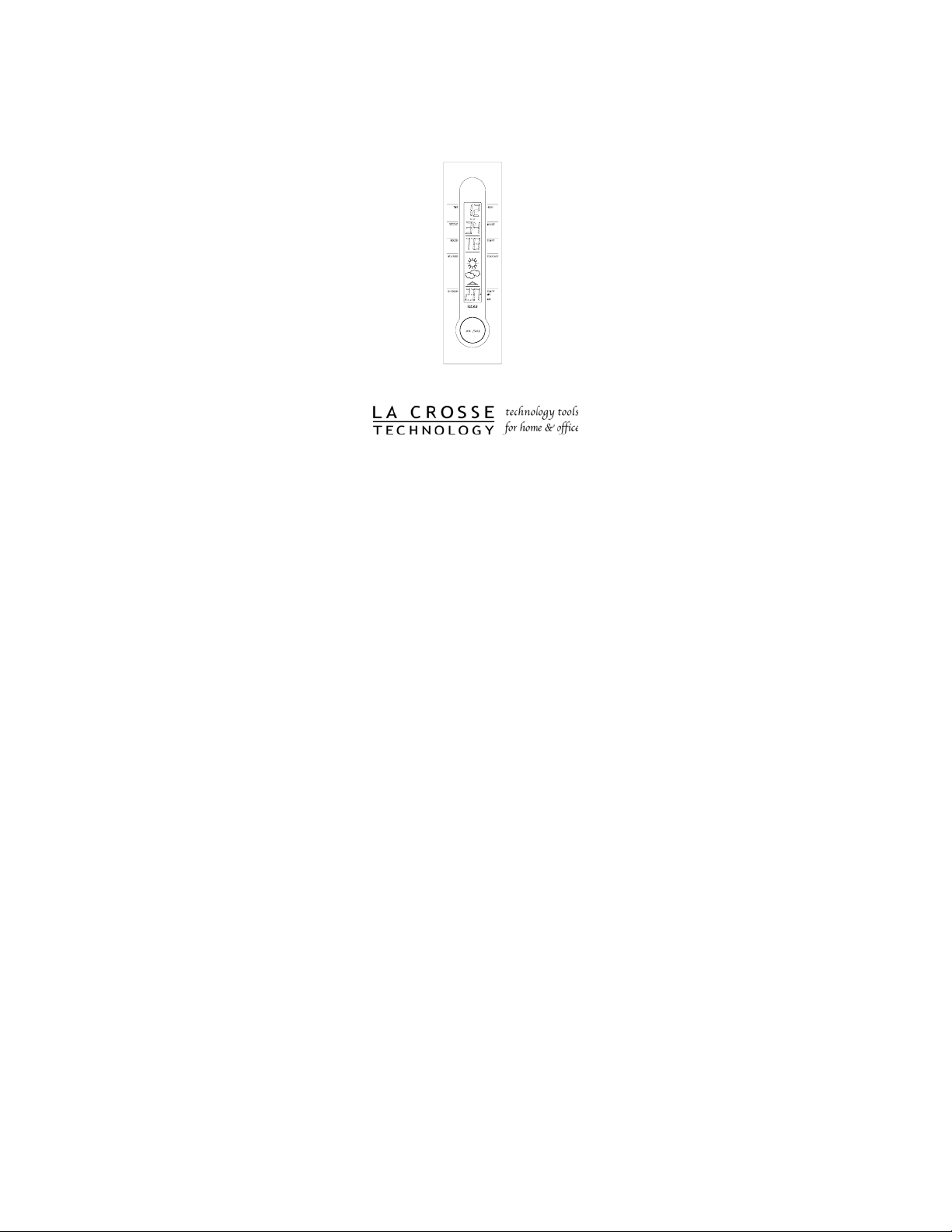
FEATURES
Note: All temperatures are read in °F, there is no
°
option to read the temperature in
C.
HOUR LCD
INDOOR LCD
OUTDOOR LCD
MINIMUM/MAXIMUM
BUTTON
9
Page 10

I. INDOOR TEMPERATURE
The Weather Temperature Station monitors the
temperature within its immediate proximity, and
displays this temperature in the INDOOR LCD.
The temperature is monitored as soon as the
batteries are installed.
II. WEATHER FORECAST
The weather forecasting feature is estimated to
be 75% accurate. The weather forecast is based
solely upon the change of air pressure over time.
The WS-7044U averages past air-pressure
readings to provide an accurate forecast—
causing a necessity to disregard all weather
forecasting for 12-24 hours after the unit has
been set-up, reset, or moved from one altitude to
another (i.e. from one floor of a building to
another). In areas where the weather is not
affected by the change of air pressure, this
feature will be less accurate.
A. WEATHER ICONS
10
Page 11

There are 3 possible weather icons that will
be displayed in the FORECAST LCD:
Sunny—indicates that the weather
is expected to improve (not that
the weather will be sunny).
Sun with
Clouds—
indicates that
the weather
is expected to be fair (not that the weather
will be sunny with clouds).
Clouds with Rain—indicates that
the weather is expected to get
worse (not that the weather will
be rainy).
The weather icons change when the unit
detects a change in air pressure. The icons
11
Page 12

change in order from: “sunny” to “sun with
clouds” to “clouds with rain,” or the reverse.
It will not change from “sunny” directly to
“rainy,” although it is possible for the
change to occur quickly. If the symbols do
not change then the weather has not
changed, or the change has been too slow
and gradual to register.
B. WEATHER TENDENCY ARROWS
Other possible displays in the FORECAST
LCD are 2 weather tendency arrows, one
that points up (under the forecast icons) and
one that points down (above the forecast
icons). These arrows reflect current changes
in the air pressure. An arrow pointing up
indicates that the air pressure is increasing
and the weather is expected to improve or
remain good, an arrow pointing down
indicates that the air pressure is decreasing
and the weather is expected to become
worse or remain poor. No arrow means the
pressure is stable.
12
Page 13

III. OUTDOOR TEMPERATURE—WITH
MINIMUM & MAXIMUM FEATURE
The Weather Temperature Station receives the
outdoor temperature from the Remote
Temperature Transmitter, and the temperature
appears in the OUTDOOR LCD. The Remote
Temperature Transmitter makes a temperature
update every 1 minute, and transmits a new
temperature to the Weather Temperature Station
3 times every 10 minutes. The Weather
Temperature Station also keeps a record of the
Minimum and Maximum temperatures it has
recorded.
13
Page 14

A. VIEWING THE MINIMUM/MAXIMUM
TEMPERATURES
1. Press the circular MIN/MAX button
(under all LCD displays) once. An
arrow will appear and point to the “MIN”
that is printed in the right-hand margin.
The minimum-recorded temperature will
display in the OUDOOR LCD.
2. Press the MIN/MAX a second time and
the arrow will shift to point to the
“MAX” that is printed in the right-hand
margin. The maximum-recorded
temperature is now displayed in the
OUTDOOR LCD.
3. Press the MIN/MAX a third time, and the
OUTDOOR LCD returns to display the
current outdoor temperature.
14
Page 15

B. RESETTING THE
MINIMUM/MAXIMUM
TEMPERATURE
1. Press and hold the MIN/MAX button for
3 seconds. This will reset all records to
the current outdoor temperature.
MOUNTING
Note:
Extreme and sudden changes in
temperature will decrease the accuracy of the
Weather Temperature Station, and changes in
elevation will result with inaccurate weather
forecasting for the next 12 to 24 hours. These
changes will require a 12 to 24 hour wait before
obtaining reliable data. To achieve a true
temperature reading, avoid mounting where
direct sunlight can reach the Remote Temperature
Transmitter. We recommend that you mount the
Remote Temperature Transmitter on a Northfacing wall. The sending range is 80ft (25m)—
obstacles such as walls, concrete, and large metal
objects can reduce the range. Place both units in
15
Page 16

their desired location, and wait approximately 10
minutes before permanently mounting to ensure
that there is proper reception. The Weather
Temperature Station should display a temperature
in the OUTDOOR LCD within 3 minutes of
setting-up.
I. THE REMOTE TEMPERATURE
TRANSMITTER
The Remote Temperature Transmitter can be
mounted in two ways:
• with the use of screws, or
• using the adhesive tape.
A. MOUNTING WITH SCREWS
1. Remove the mounting bracket from the
Remote Temperature Transmitter. The
bracket should snap off easily.
2. Place the mounting bracket over the
desired location. Through the three
screw holes of the bracket, mark the
mounting surface with a pencil.
16
Page 17

3. Where marked, start the screw holes
into the mounting surface.
4. Screw mounting bracket onto the
mounting surface. Ensure that the
screws are flush with the bracket.
5. Snap the Remote Temperature
Transmitter onto the mounted bracket.
B. MOUNTING WITH ADHESIVE TAPE
1. With a nonabrasive solution, clean and
dry the back of the mounting bracket
and the mounting surface to ensure a
secure hold. The mounting surface
should be smooth and flat.
2. Remove the protective strip from one
side of the tape. Adhere the tape to the
designated area on the back of the
mounting bracket.
3. Remove the protective strip from the
other side of the tape. Position the
Remote Temperature Transmitter in the
desired location, ensuring that the
Weather Temperature Station can
17
Page 18

receive the signal.
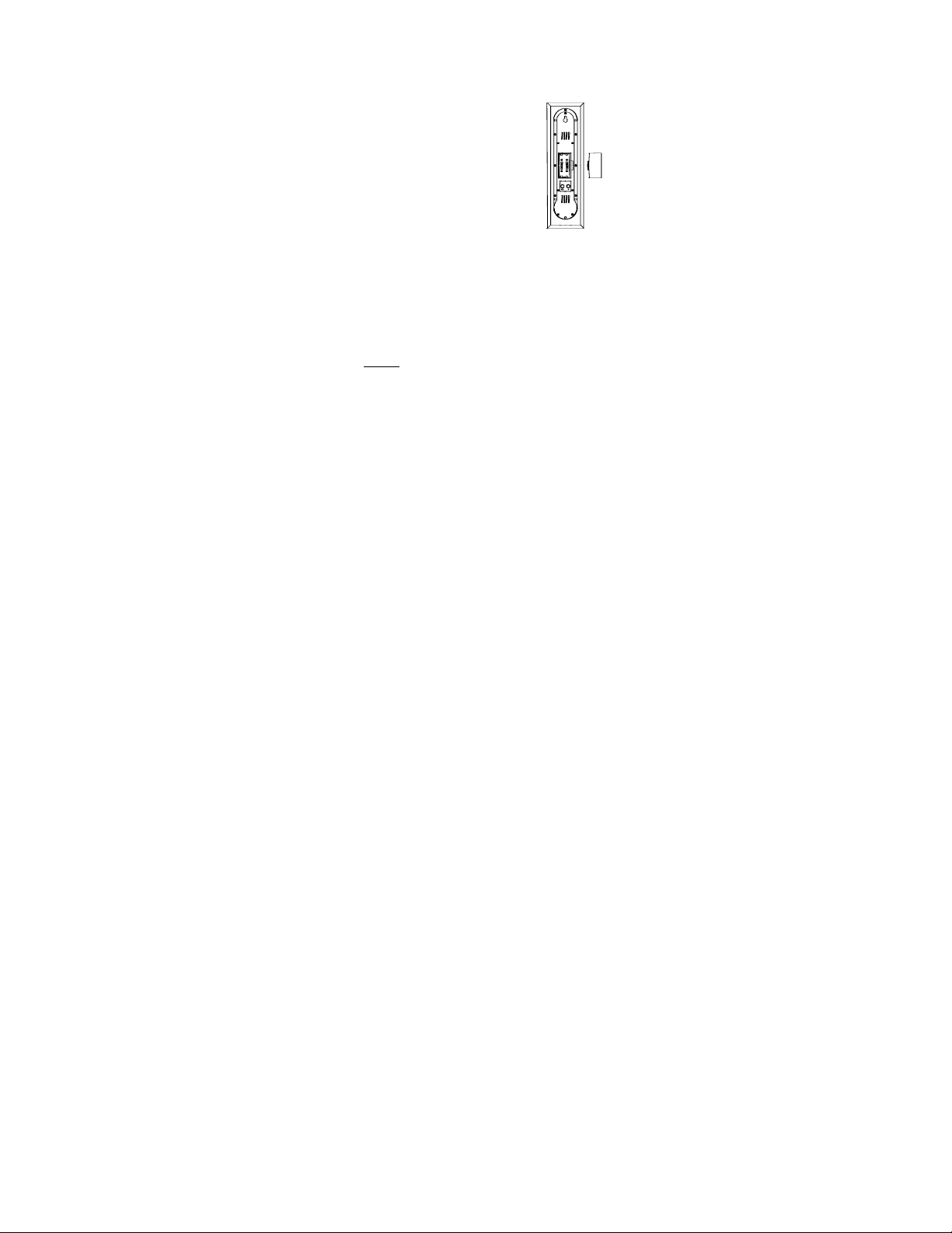
THE WEATHER STATION
II.
The Weather Station can be mounted on the wall
with the use of a wall hanging screw (not
included).
A. WALL MOUNTING
1. Place a screw (not included) into an
appropriate wall, leaving approximately
3/16 of an inch (5mm) extended from
the wall.
2. Place the Weather Station onto the
screw using the hanging hole on the
backside. Gently pull the Station down
to lock the screw into place.
TROUBLESHOOTING
Problem: No outdoor temperature is displayed.
Solution: 1) Remove all batteries—wait 30
seconds—then reinsert into transmitter
18
Page 19

first, then into the station.
2) Place transmitter closer to station.
3) Be sure there are no obstructing
objects.
4) Be sure all batteries are fresh.
Problem: The LCD screens are faint/dim.
Solution: Replace batteries.
Note:
For problems not solved, please contact La
Crosse Technology.
19
Page 20

MAINTENANCE AND CARE INSTRUCTIONS
• Extreme and sudden temperature changes,
vibration, and shock should be avoided to
prevent damage to the units.
• Clean displays and units with a soft, damp
cloth. Do not use solvents or scouring
agents; they may mark the displays and
casings.
• Do not submerge in water.
• Immediately remove all low powered
batteries to avoid leakage and damage.
• Opening the casings invalidates the
warranty. Do not try to repair the unit.
Contact La Crosse Technology for repairs.
20
Page 21

SPECIFICATIONS
Temperature measuring range
Indoor:
32°F to 104°F with 0.2°F
resolution: (0°C to 40°C with
0.1°C resolution). “OFL”
displayed if outside this range.
Outdoor:
-21.9°F to 157.9°F with 0.2°F
resolution: (-29.9°C to 69.9°C
with 0.1°C resolution). “OFL”
displayed if outside this range.
Temperature checking intervals
Indoor: Every 10 seconds.
Outdoor: 3 times every 10 minutes.
Transmitting
433.92 MHz
frequency:
Temperature
transmitting
Maximum 80ft (25m): in open
space and free from interference.
range:
21
Page 22

Power Source
Weather
Station:
Transmitter: 2 x AAA, 1.5V (IEC LR3)
Dimensions (L x W x H)
Weather
Station:
Transmitter: 2.32 x 0.83 x 2.56in. (59 x 21 x
2 x AAA, 1.5V (IEC LR3)
2.95 x 0.83 x 10in. (75 x 21 x
255mm)
65mm)
22
Page 23

WARRANTY INFORMATION
La Crosse Technology provides a 1-year warranty on this weather
station. Contact La Crosse Technology immediately upon
discovery of any defects covered by this warranty.
Before sending the Weather Station in for repairs, contact La
Crosse Technology. The Weather Station will be repaired or
replaced with the same or similar model.
This warranty does not cover any defects resulting from improper
use, unauthorized repairs, faulty batteries, or the Weather Stations
inability to receive a signal due to any source of interference.
LA CROSSE TECHNOLOGY WILL NOT ASSUME LIABILITY
FOR INCIDENTAL, CONSEQUENTIAL, PUNITIVE, OR
OTHER SIMILAR DAMAGES ASSOCIATED WITH THE
OPERATION OR MALFUNCTION OF THIS WEATHER
STATION. THIS PRODUCT IS NOT TO BE USED FOR
MEDICAL PURPOSES OR FOR PUBLIC INFORMATION.
THIS PRODUCT IS NOT A TOY. KEEP OUT OF CHILDRE’S
REACH.
This warranty gives you specific legal rights. You may also have
other rights specific to your State. Some States do no allow the
exclusion of consequential or incidental damages therefore the
above exclusion of limitation may not apply to you.
For warranty work, technical support, or information contact
23
Page 24

La Crosse Technology
700 East Main Street
Spring Grove, MN 55974
Phone: 507.895.7095
Fax: 507.895.8000
support@lacrossetechnology.com
sales@lacrossetechnology.com
(information on other products)
www.lacrossetechnology.com
All rights reserved. This handbook must not be reproduced in any
form, even in excerpts, or duplicated or processed using electronic,
mechanical or chemical procedures without written permission of
the publisher.
This handbook may contain mistakes and printing errors. The
information in this handbook is regularly checked and corrections
made in the next issue. We accept no liability for technical
mistakes or printing errors, or their consequences.
All trademarks and patents are acknowledged.
e-mail:
(warranty work)
web:
24
 Loading...