

La Crosse Technology WS-7016U User Manual
WS-7016U
Wireless 433 MHz
Temperature Station
Instruction Manual
1
Topic Page
Inventory of Contents
Additional Equipment
Quick Setup
Detailed Setup Guide
Battery Installation 3-6
Remote Control Sender 3-4
Setting the Time 7-8
Selecting Units of Measurement 8
Features
Indoor Minimum and Maximum
Temperatures
Outdoor Minimum and
Maximum Temperatures
Resetting the Indoor Minimum
and Maximum Temperatures
Resetting the Outdoor Minimum
Reading the Temperature Trend 13
Mounting
TABLE OF CONTENTS
1
1
2
Indoor Temperature Station 5-6
9
10-11
11-12
12
and Maximum Temperatures
2
Remote Control Sender 13-16
Indoor Temperature Station 16-18
Using Multiple Remote Control Senders
Setup of Multiple Units 18-21
Viewing Remote Control
Senders
Features of the Multiple Remote
Control Senders
Troubleshooting
Maintenance and Care Instructions
Specifications
Warranty Information
FCC DISCLAIMER
INVENTORY OF CONTENTS
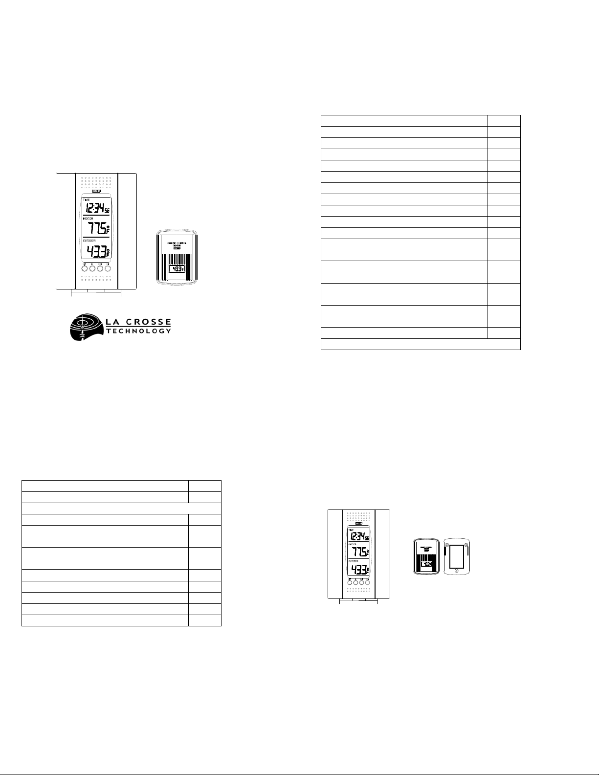
1. The Indoor Temperature Station (Figure 1)
2. The Outdoor Remote Control Sensor
(TX3U) and mounting bracket. (Figure 2)
3. 3 each, 1/2” Philips screws.
4. One strip of double sided adhesive tape.
21-22
22-23
24-28
28-29
29-31
31-33
34
3
5. Instruction Manual and Warranty Card.
Figure 1
Figure 2
ADDITIONAL EQUIPMENT (not included)
1. 1 Philips screwdriver.
2. 1 Flat screwdriver.
3. 2 Fresh AA 1.5V batt eries.
4. 2 Fresh AAA 1.5V batteries.
QUICK SETUP
1. Insert two AAA batt e ries into the Remote
Control Sender.
2. Insert two AA batteries into the Indoor
Temperature Station.
4
3. Wait 5-6 minutes, or until the outdoor
temperature is displayed in the OUTDOOR
LCD (Liquid Crystal Display) of the Indoor
Temperature Station.
4. Set the Time (See complete instructions
for details).
5. Mount units.
Note:
The Remote Control Sender transmits a
signal every 3 minutes. After the batteries have
been installed, the Indoor Temperature Station
searches for these signals for a duration of 6
minutes. If there is no temperature reading in
the OUTDOOR LCD after 6 minutes, make
sure the units are within range of each other, or
repeat battery installation process.
DETAILED SETUP GUIDE
I. BATTERY INSTALLATION
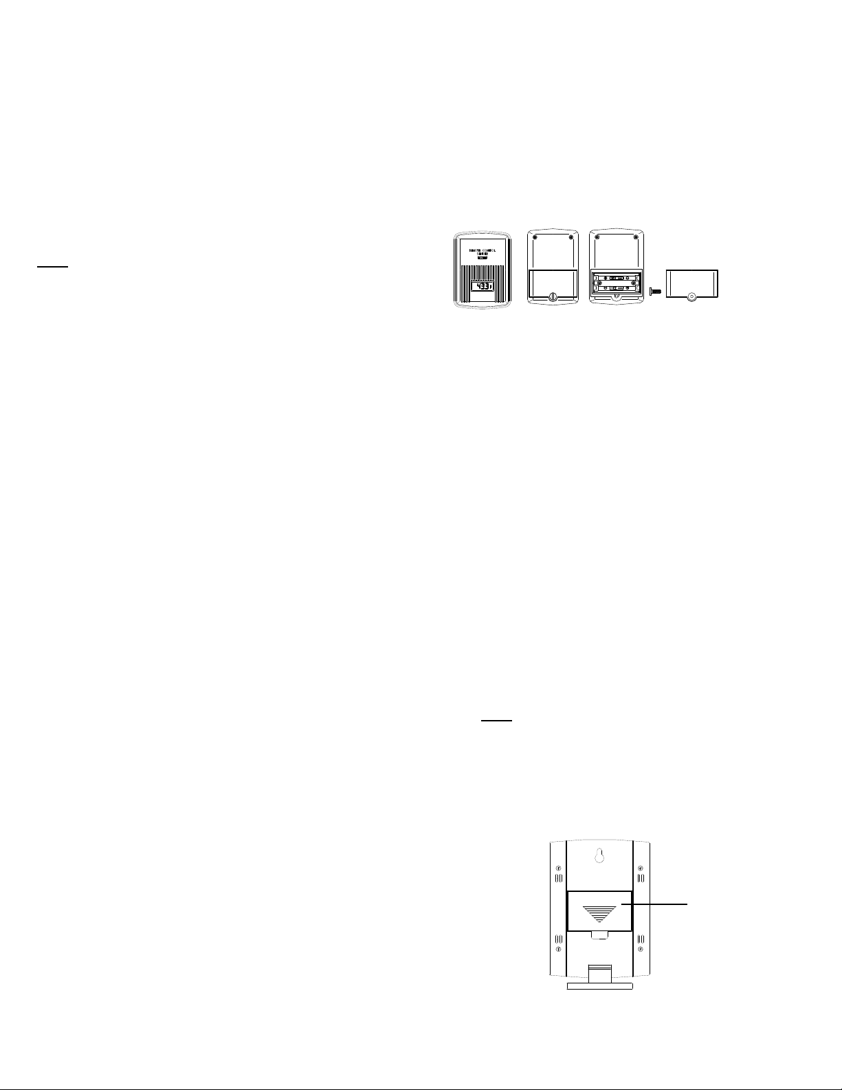
A. REMOTE CONTROL SENDER
Battery cover
Battery compartment
1. Remove the mounting bracket.
The bracket snaps on and off with
minimal effort.
2. Remove battery cover. To do this,
remove the flathead screw located
in the lower-cen tral position of the
unit. The rubber weather-seal
creates a tight seal for the battery
cover, and does not allow the
battery cover to fall away from the
unit. Place the screw partially back
into the hole and a n gle it slightly,
so the threads grab the battery
cover. With the screw, pull the
battery cover off.
3. Observing the correct polarity,
install 2 AAA batter ie s. The
batteries will fit tigh tly—make
sure they do not spring free, or
start-up problems may occur.
4. Check the LCD screen of the
Remote Control Sender to se e if
there is a temperature reading. If
there is no reading check the
polarity of the batteries or replace
with new batteries.
5. Observing that the rubber
weather-seal is in place; replace
battery cover, screw, and
mounting bracket.
5
6
B. INDOOR TEMPERATURE
STATION
After the batteries are installed, DO
Note:
NOT press any buttons. This may interfere
with the signals, causing temperatures to
register incorrectly.
1. Remove the battery cover on the
backside. To do this, push up and
pull out.
Battery
Cover
7
8
2. Observing the correct polarity,
install 2 AA batteries.
3. Replace battery cover.
4. Wait 5-6 minutes or until both
indoor and outdoor temperatures
are shown on the Indoor
Temperature Station.
5. The Indoor Temperature Station
should now show: “-:- -” in the
TIME LCD, and temperatures in
the INDOOR and OUTDOOR
LCD’s.
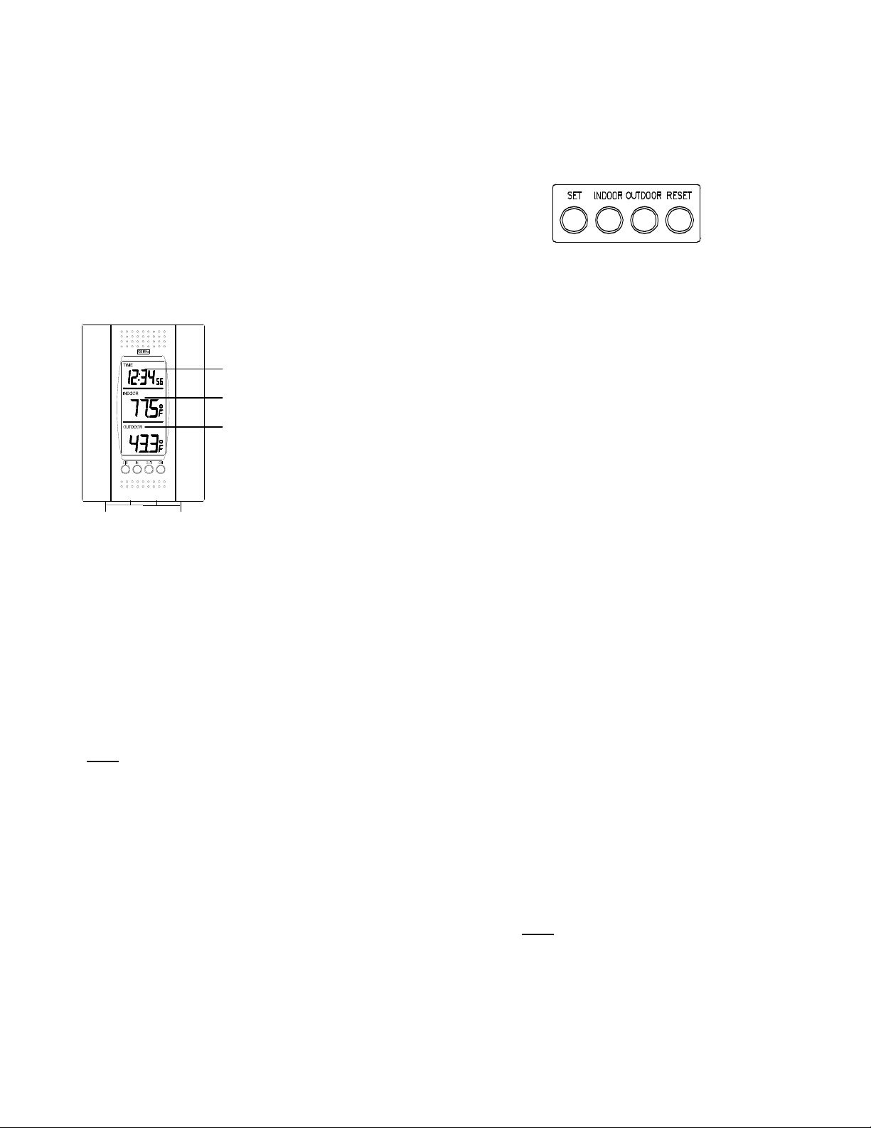
TIME LCD
INDOOR LCD
OUTDOOR LCD
II. TIME
Control Buttons
A. SETTING THE TIME
1. Press and hold the SET button for
1 second. “12h” will appear in the
TIME LCD.
2. Use the INDOOR button to select
either 12h time or 24h time (12h is
an AM—PM mode, and 24h is
military time).
3. Press the SET button 2 times,
“TIME” will flash in the upper left
corner.
4. Press the INDOOR button to set
the hours, and press the
OUTDOOR button to set the
minutes.
5. Press the SET button to activate
the clock.
There is only a “PM” display,
Note:
which appears under “TIME.” If there
is no display here it is AM. Make sure
you set the time accordingly.
III. UNITS OF TEMERATURE MEASURE
A. SELECTING UNITS OF
MEASUREMENT
1. Press and hold the SET button for
1 second.
2. Press the SET button again. “F”
will appear in the TIME LCD.
3. Press the INDOOR button to shift
between F and C.
4. Press the SET button twice to
activate settings.
9
IV. FEATURES
A. INDOOR MINIMUM AND
MAXIMUM TEMPERATURES
1. Press and hold the INDOOR
button for 1 second. “MIN”
appears in the INDOOR LCD and
the recorded minimum
temperature is displayed.
2. Press and hold the INDOOR
button for 1 second. “MAX”
appears in the INDOOR LCD and
the recorded maximum
temperature is displayed.
When first setting-up the
Note:
minimum and ma ximum temperatures
may be the same as the current
temperatures.
3. To return to the current
temperature, press and hold the
INDOOR button for 1 second.
10
11
12
 Loading...