

La Crosse Technology WS-1516U-IT User Manual
PROFESSIONAL WEATHER CENTER
WS-1516-IT
Table of Contents
Topic Page
Features 4
Setting up 7
Function keys 14
LCD Screen 16
Manual Setting 19
Time alarm setting 26
Weather alarm operations 27
Hysteresis 32
Weather forecast and weather tendency 33
Wind direction and wind speed measurement 37
Rainfall measurement 38
Viewing history data 39
Viewing the min/ max weather data 41
Switch On/ Off buzzer 50
Outdoor transmission 915 MHz reception 51
Positioning 53
Instruction Manual
Care and Maintenance 57
Specification 58
Warranty Info 61
FAQ 63
1
PROFESSIONAL WEATHER CENTER
WS-1516-IT
Congratulations on purchasing this state-of-the-art Professional Weather Center as an example
of excellent design and innovative technology. Featuring time, date, calendar, weather forecast,
wind direction and speed, rainfall, indoor temperature, outdoor temperature and outdoor humidity,
air pressure and various alarm settings for different weather conditions, this Weather Center will
provide you with extensive weather information and forecast.
This product offers:
Instruction Manual
INSTANT TRANSMISSION is the state-of-the-art new wireless
transmission technology, exclusively designed and developed
by LA CROSSE TECHNOLOGY. INSTANT TRANSMISSION
offers you an immediate update (every 4.5 seconds!) (6.5
seconds for rain) of all your outdoor data measured from the
transmitters: follow your climatic variations in real-time!
3
FEATURES:
Weather Center
LCD
Time display (manual setting)
12/24 hour time display
Calendar display (weekday, date, month, year)
Time alarm function
2
4
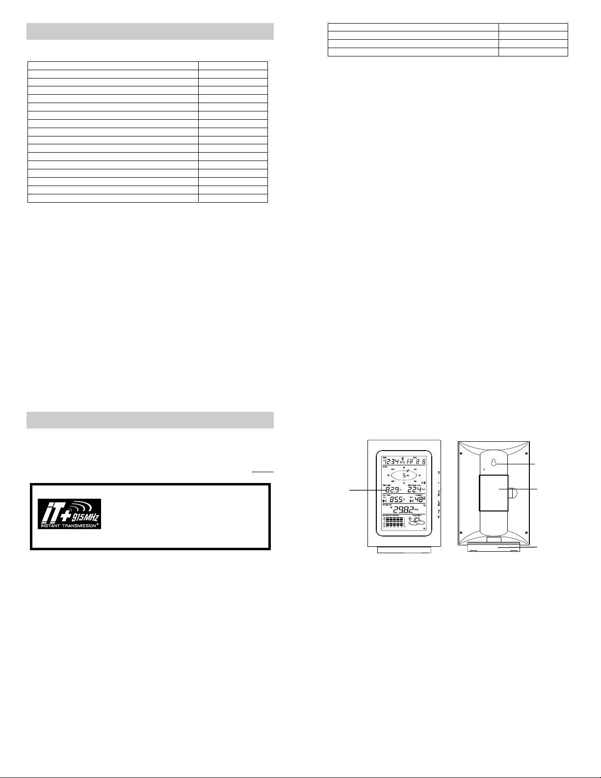
Hanging hole
Battery
compartment
Stand
Weather forecasting function with 3 weather icons and weather tendency indicator
r
Dew point display in ºF/°C
Outdoor temperature display in ºF/°C
Outdoor Humidity display as RH%
Indoor temperature display in ºF/°C
Display MIN/MAX value of outdoor temperature, outdoor humidity, dew point, wind chill and
relative pressure with time and date of recording
Display MAX value of wind speed, gust and 24h rainfall
Low/High outdoor temperature and humidity alarm
Relative air pressure displayed in inHg or hPa
Air pressure tendency indicator for the past 12 hours (bar graph format)
LCD contrast selectable
Low battery indicator
Wind direction dis played in 16 steps
Wind speed and gust displayed in mph, km/h, or m/s
Wind speed displayed in Beaufort scale
Wind chill displayed in °F or °C
High alarm function for wind speed
Manual reset of outdoor temperature, outdoor humidity, dew point, wind chill, pressure,
wind speed, gust, 24h rainfall(does not always reset 24 hour) and total rainfall
24h rainfall display in inch or mm
Total rainfall display in inch or mm
Storm warning alarm
Buzzer on/off selectabl e
Storage of 140 sets of history weather data recorded in 3-hour intervals
Wireless transmission at 915 MHz
Transmission range up to 330 feet (100 meters)
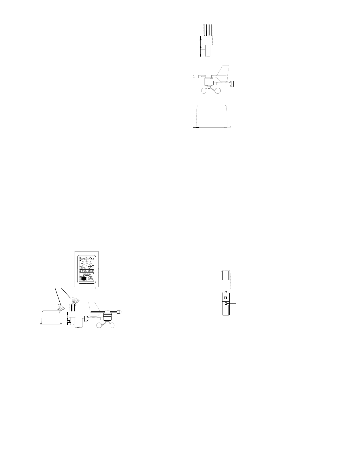
5
Thermo-hygro Sensor
Wind Sensor
Rain Sensor
Remote transmission of the outdoor temperature and humidity to the
Weather-resistant casing
Wall mounting case (to be mounted in a sheltered place. Avoid direct rain
Weather Center at 915 MHz
and sunshine)
Connected to the thermo-hygro sensor by cable
Can be installed onto a mast or a horizontal panel
Remote transmission of the rainfall data to the Weather Center
at 915 MHz
To be mounted onto a horizontal panel
6
SETTING UP:
Note:
Wireless transmission
at 915 MHz - thermohygro and rain sensor
to the Weather Center
Rain senso
Cable connection between the wind
sensor and the thermo-hygro sensor
When putting the Weather Center into operation, it is important to perform in close proximity (e.g.
on a table about 5 ft apart) a complete wiring and set-up of the system. This step is important to
test all components for correct function before placing and mounting them at their final
destinations (See Positioning below). Spin the wind vane and tip the rain gauge to test.
1. Unwind the cables of the Wind sensor. Connect the Wind sensor to the Thermo-hygro
transmitter by plugging the connector head into the socket of the Thermo-hygro sensor.
Cord should “click” into place.
Weather Center
Wind sensor
7
2. First insert the batteries into the Thermo-hygro sensor and Rain sensor “How to install
and replace the batteries into the Thermo-hygro sensor“ and “How to install and
replace the batteries into the Rain sensor” below).
3. Then insert the batteries into the Weather Center (see “How to install and replace the
batteries into the Weather Center” below). Once the batteries are installed, all segments
of the LCD will light up briefly and a short signal tone will be heard. It will then display the
time as 12:00, the date as 1.1.05, the weather icons, and air pressure value. "- - -" will be
shown for outdoor data.
Sockets for wind sensor
8
4. Afterwards, the Weather Center will start receiving data from the transmitter. The
transmission rece ption icon will be bl inking to indicat e that the station is trying to get the
thermo-hygro transmitter data. The outdoor temperature, humidity, wind data should then
be displayed on the Weather Center. If this does not happen after 135 seconds, the
batteries will need to be removed from all units. You will have to start again from step 2.
5. The transmitter reception icon is now blinking again to indicate that the station is trying to
get the rain sensor data. It will stop blinking once the rain sensor has been detected. If this
does not happen after 135 seconds, you will need to start again from step 2.
6. You may need to check the cable for correct connection and all the components for correct
function by manually turning the wind-gauge by moving the wind-vane; tilting the rain
sensor to hear the impact of the internal moving seesaw, etc. (see Positioning below).
7. Time and date shall be manually set (See Manual Setting below).
8. After the Weather Center has been checked for correct function with regard to the above
points and found fit, the initial set up of the weather station system is finished and the
mounting of the system components can take place. It must be ensured however that all
components work properly together at their chosen mounting or standing locations. If e.g.
there appear to be problems with the 915 MHz radio transmission, they can be overcome
by slightly changing the mounting locations or turning the base station.
Note:
The radio communication between the receiver and the transmitters in the open field reaches
distances of max 330 feet, provided there are no interfering obstacles such as buildings, trees,
vehicles, high volt age lines, etc.
9. Radio interferences created by PC screens, radios or TV sets can in some cases entirely
cut off radio communication. Please consider this when choosing standing or mounting
locations.
9
Note :
After batteries are installed in the transmitter, install the batteries in the weather center to
receive the signal from the transmitters as soon as possible. If the weather center is
powered more than 5 hours after the transmitter is powered, the weather center will never
receive signal successfully from the transmitters. In this case, user will need to reinstall the
batteries from all the transmitters to redo set-up procedure.
After batteries are installed, there will be synchronization between weather center and the
transmitters. At this time, the signal reception icon will be blinking. When the signal is
successfully received by the weather center, the icon will be switched on. (If it is not
successful, the icon will not be shown in LCD) So the user can easily see whether the last
reception was successful (icon on) or not (icon off). On the other hand, the short blinking of
the icon shows that a reception is in progress.
If the signal reception is not successful on the first frequency (915MHz) for 45 seconds, the
frequency is changed to 920MHz and the learning is tried another 45 seconds. If still not
successful, the reception is tried for 45 seconds on 910MHz. This will also be done for resynchronization.
Transmitter signal
reception icon
10
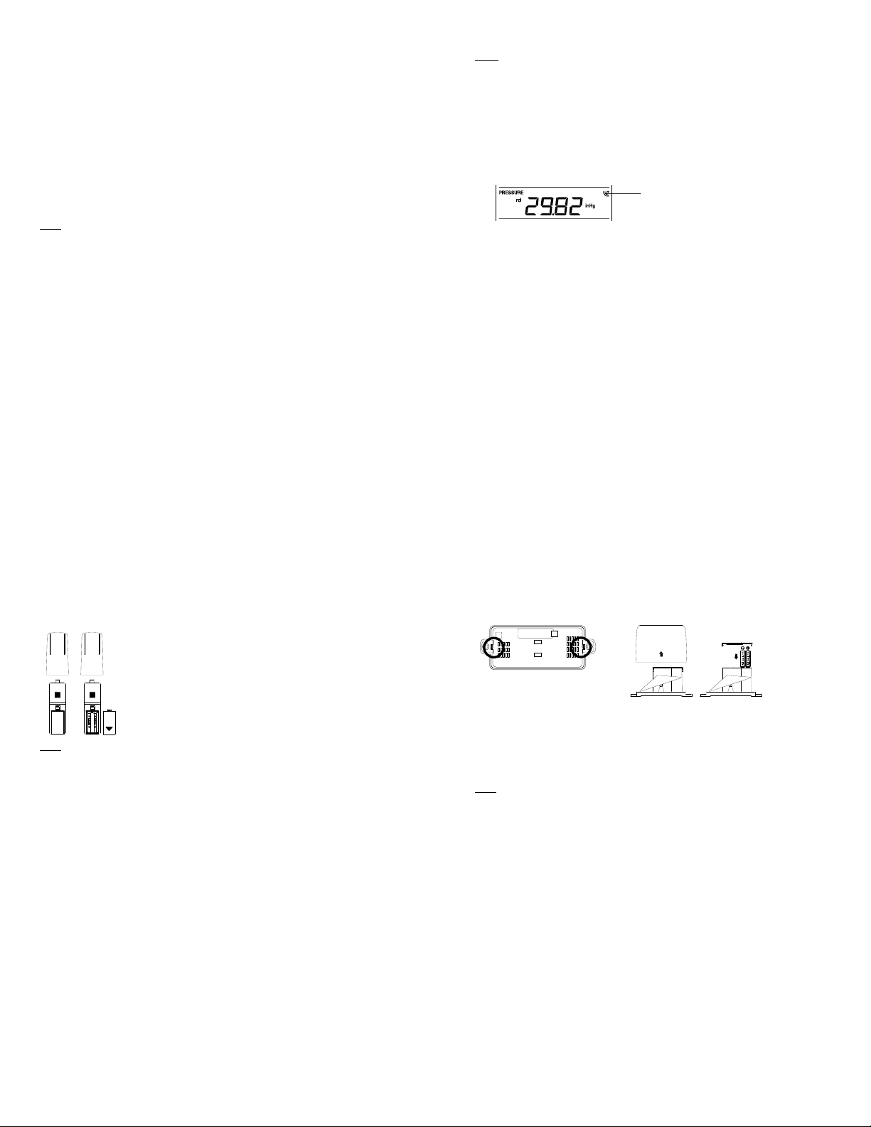
HOW TO INSTALL AND REPLACE THE BATTERIES INTO THE THERMOHYGRO SENSOR
Note:
In the event of changing batteries in any of the units, all units need to be reset by following the
setting up procedures. This is because a random security code is assigned by the thermo-hygro
sensor at start-up and this code must be received and stored by the Weather Center in the first
several minutes of power being supplied to it.
The outdoor Thermo-hygro sensor works with 2 x AA, IEC LR6 1.5V
Alkaline batteries. To install and replace the batteries, please follow the
steps below:
1. Uninstall the rain cover of the transmitter.
2. Remove the battery compartment cover.
3. Insert the batteries, observing the correct polarity (see the marking
in the battery compartment).
4. Replace the battery cover.
11
HOW TO INSTALL AND REPLACE THE BATTERIES INTO THE RAIN SENSOR
Figure 1
The rain sensor works with 2 x AAA, IEC LR3, 1.5V Alkaline batteries. To install and replace the
batteries, please follow the steps below:
1. Press tabs back to unlock rain sensor cover. (Figure 1)
2. Lift rain sensor cover to access battery compartment. (Figure 2)
3. Insert the batteries, observing the correct polarity (see the marking in the battery
compartment). (Figure 3)
4. Replace the battery cover and the rain cover onto the unit.
Note:
In the event of changing batteries in any of the units, all units need to be reset by following the
setting up procedures. This is because a random security code is assigned by the rain sensor at
start-up and this code must be received and stored by the Weather Center in the first several
minutes of power being supplied to it.
Figure 2
Figure 3
12
A
HOW TO INSTALL AND REPLACE THE BATTERIES INTO THE WEATHER
CENTER
The Weather Cent er works with 3 x AA, IEC LR6, 1.5V Alkal ine
batteries. When the batteries need to be replaced, the low battery
symbol will appear on the LCD. To install and replace the
batteries, please follow the steps below:
1. Remove the battery compartment cover.
2. Insert the batteries observing the correct polarity (see the
marking in the battery compartment).
3. Replace the battery cover.
BATTERY CHANGE:
It is recommended to replace the batteries in all units every 24 months to ensure optimum
accuracy of these unit s.
Please participate in the preservation of the environment. Return used batteries
to an authorized depot.
Note:
The stored History record will not be kept after the battery change is done on the Weather
Center.
13
FUNCTION KEYS:
Weather Center:
The Weather Center has 5 easy-to-use function keys.
SET key
Press and hold to enter manual setting modes: LCD contrast, Manual time setting, 12/24
hour time display, Calendar setting, ºF/ ºC temperature unit, Wind speed unit, Rainfall unit,
14
SET
key
+ key
HISTORY key
LARM key
MIN/MAX key
Pressure unit, Relative pressure reference setting, Weather tendency threshold setting,
Storm warning threshold setting and Storm Alarm On/ Off setting
Press to toggle between the display of Mode 1 or Mode 2:
Mode 1: "Wind speed + outdoor temp + rel. pressure"
Mode 2: "Gust + Dew Point temp + rainfall"
(Mode 2 displayed will be shown for 30 seconds. Then it will
return to normal display automatically.)
In normal display mode, press and hold to switch on/ off the Buzzer
In the weather alarm setting mode, press and hold to adjust different alarm value and
switch the alarm On/ Off
Press to activate the reset mode when max or min record is shown
Stop the alarm during the time alarm or weather alarm ringing
+ key
In display Mode 1, press to toggle between the display of Preset alarm time, date, weekday
+ date, Indoor temp, or second in the time display
In display mode 2, press to toggle between the display of Rel. Pressure, 24 hour rainfall
and Total rainfall
Press to adjust (increase) the level of different settings
Stop the alarm during the time alarm or weather alarm ringing
Press to confirm to reset the max/min record
Press to reset the total rainfall amount to 0
HISTORY key
Press to display the we ather data histor y records
Stop the alarm during the time alarm or weather alarm ringing
Press to exit manual setting mode and alarm setting mode
15
ALARM key
Press to enter the time alarm and weather alarm setting mode
Confirm partic ular alarm setting
Press to exit the manual setting mode
Stop the alarm during the time alarm or weather alarm ringing
Press to exit max/ min record display mode
MIN/MAX key
Press to display minimum and maximum records of various weather data
Press to adjust ( decrease) the l evel of differen t settings
Stop the alarm during the time alarm or weather alarm ringing
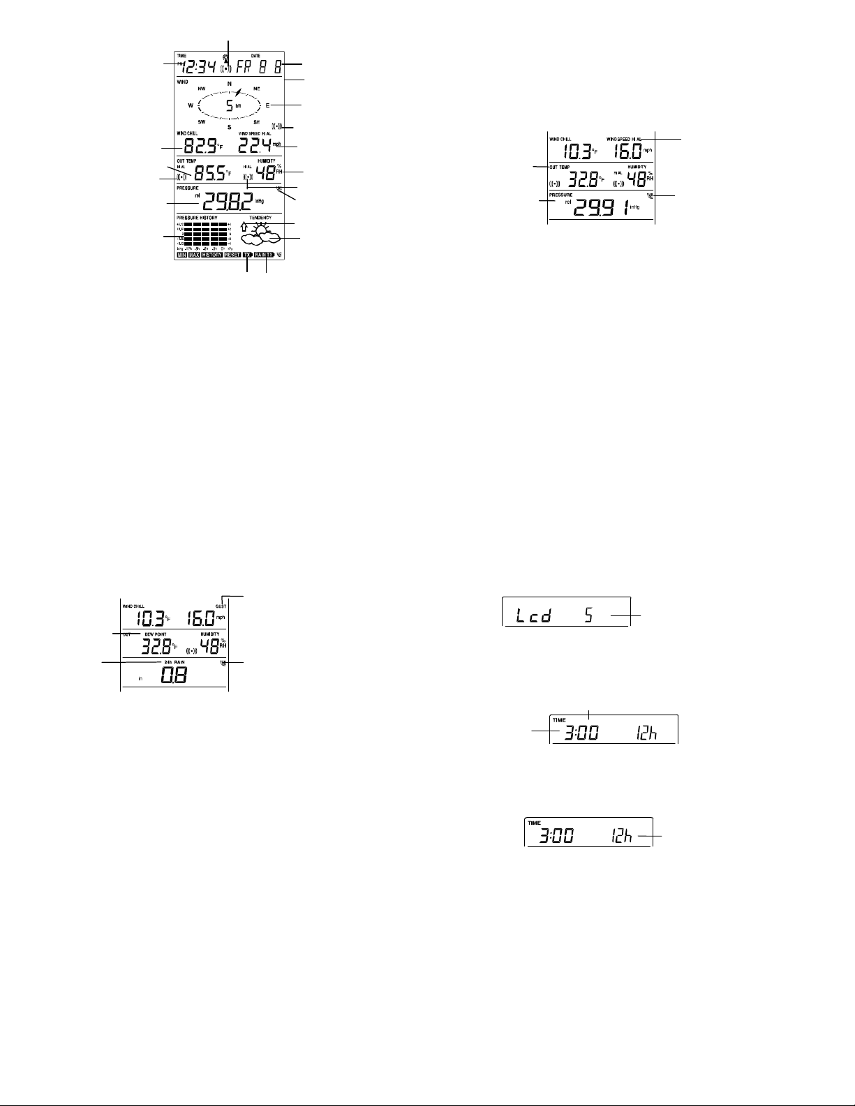
LCD SCREEN
The LCD screen is split into 5 sections displaying the following information:
1. Time and date/ indoor temp/ second
2. Wind data
3. Outdoor temperature, Dew point and humidity,
4. Air pressure, Rainfall data,
5. Air pressure history and Weather forecast icon.
16
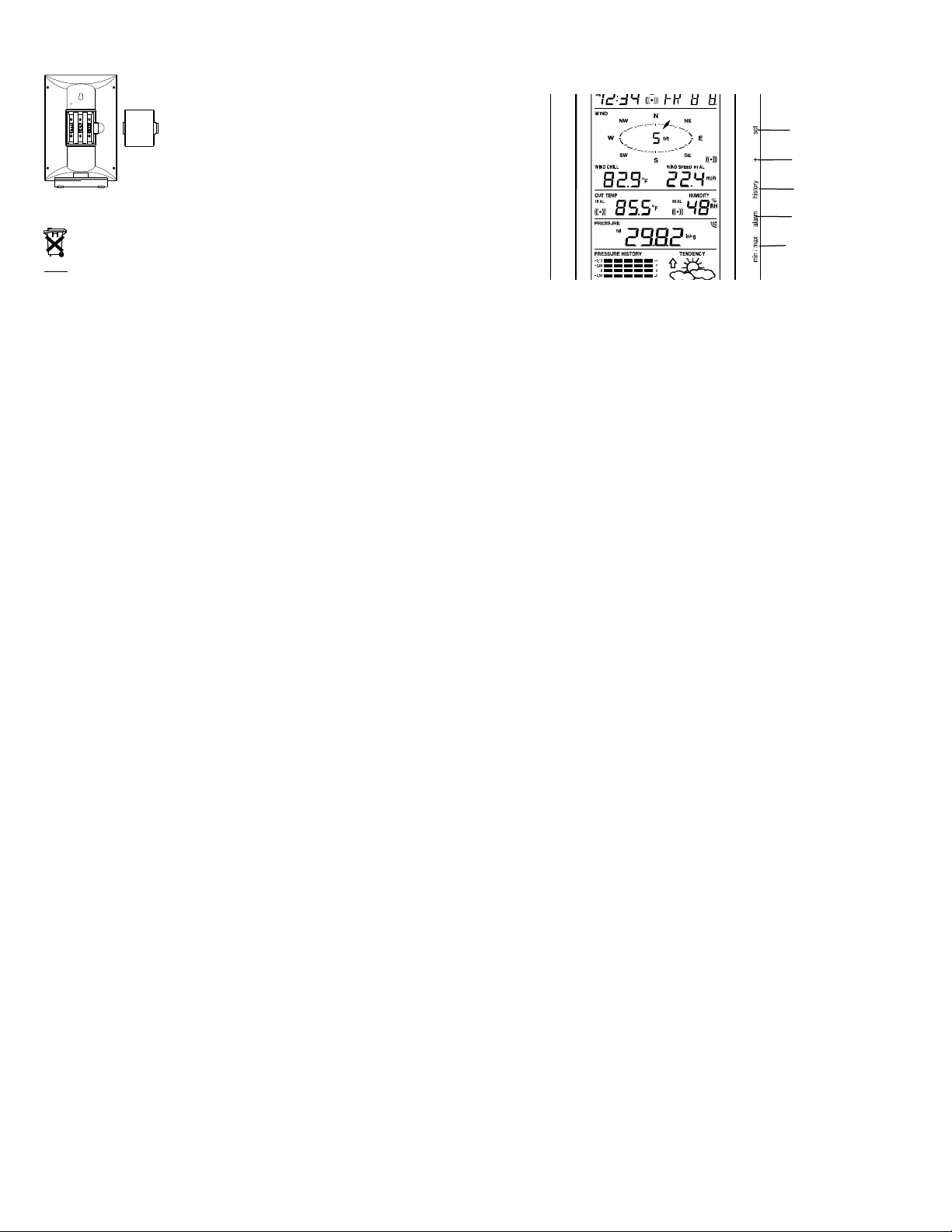
t
play
y
A
r
p
r
Outdoor temperature or dew poin
Relative air pressure
display in inHg or hPa, o
total and 24 h rainfall
display in inch or mm
Time displa
Wind Chill
in °F or °C
in °F or ºC
Outdoor temp.
alarm icon
ir pressure
histogram
Low battery Indicator (Thermo-hygro)
Time alarm icon
17
Calendar, indoor temp.,
or alarm time dis
Buzzer off indicator
Wind direc tion displa y
and wind speed in
Beaufort sc ale
Wind speed Hi
alarm icon
Wind speed or gust
h, km/h or m/s
in m
Outdoor relative
humidity in %
Outdoor Humidity
alarm icon
Transmitter signal
reception icon
Weather tendency
indicator
Weather fo recast
icon
Low battery Indicator (rain sensor)
* When the signal from the transmitter/ or Rain sensor is successfully received by the Weather
Station, this icon will be switched on. (If not successful, the icon will not be shown on the LCD).
User can therefore easily see whether the last reception was successful (“ON” icon) or not
(“OFF” icon). On the other hand, the short blinking of the icon shows that a reception is being
done at that time.
*In normal display user may press the SET key shortly to toggle between Mode 1 and Mode 2
display:
Mode 1 : Wind speed, outdoor temperature and relative pressure reading are shown.
Outdoor temp
icon
Rel Pressure
icon
18
Wind speed icon
In Mode 1, this reception
icon is showing the
condition of the
reception of the signal
from Thermo-hygro
transmitter
Mode 2 : Wind Gust, Dew Point temperature and 24 Hour and Total Rainfall reading are shown.
Dew point icon
Rainfall icon
MANUAL SETTING:
The following manual settings can be changed once the SET key is pressed and hold for about 2
seconds:
LCD contrast setting
Manual time setting
12/24 hour time display
Calendar setting
°F/ °C temperature unit setting
Wind speed unit
Rainfall unit setting
Air pressure unit setting
Relative pressure reference value setting
Weather tendency threshold value
Storm warning thr eshold value
Storm alarm On/ Off setting
19
Wind gust icon
In Mode 2, this
reception icon is
showing the condition
of the reception of the
signal from Rain
sensor
LCD CONTRAST SET TING
The LCD contrast can be set within 8 levels, from "LCD 1" to "LCD 8" (default setting is LCD 5):
1. Press the SET key, the contrast l evel digit will s tart flashing.
2. Use the + or MIN/MAX key to adjust the level of contrast.
3. Confirm with the SET key and enter the MANUAL TIME SETTIN G.
MANUAL TIME SETTING:
You then may manually set the time of the clock by following the steps below:
1. The hour digit will start flashing.
2. Use the + or MIN/MAX key to set the hour.
3. Press the SET key to switch to the minutes. The minute digit will start flashing.
4. Use the + or MIN/MAX key to set the minute.
5. Confirm the time with the SET key and enter the 12/24 HOUR TIME DISPLAY SETTING.
12/24 HOUR TIME DI SPLAY SETTING:
Hou
flashing
Minutes fl ashing
Flashing
Digit flashing
20
The time can be set to view as 12-hour or 24-hour format. The default time-display mode is 12-h.
To set to 24-h time display:
1. Use the + or MIN/MAX key to toggle the value.
2. Confirm with the SET key and enter the CALENDAR SETTING.
CALENDAR SETTING:
The date default of the Weather Center is 1. 1. of year 2005. The date can be set manually by
proceeding as follows.
1. The year digit starts flashing.
2. Use the + or MIN/MAX key to set the year. The range runs from "00" (2000) to "99" (2099).
3. Press the SET key to confirm the year and enter the month setting. The month digit will
4. Use the + or MIN/MAX key to set the month.
5. Press the SET key to confirm the month and enter the date setting mode. The date digit will
6. Use the + or MIN/MAX key to set the date.
7. Confirm all calendar settings with the SET key and enter the °F/°C TEMPERATURE UNIT
"Date. Month." (for 24h time display)
"Month. Date." (for 12h time display)
start flashi ng.
start flashi ng.
SETTING.
Year
21
°F/°C TEMPERATURE UNIT SETTING
The temperature display can be selected to show temperature data in °F or °C. (default °F)
1. The temperature unit is flashing
2. Use the + or MIN/MAX key to toggle between “°F” or “°C”.
3. Confirm with the SET key and enter the WIND SPEED UNIT SETTING.
WIND SPEED UNIT SETTING
The wind speed unit can be set as mph (mile per hour), km/h (kilometer per hour), or m/s (meter
per second). The default unit is mph.
1. Use the + or MIN/MAX key to toggle between the unit “mph”, “km/h” or “m/s”
2. Confirm with the SET key and enter the RAINFALL UNIT SETTING.
RAINFALL UNIT SETTING
The rainfall unit can be set as inch or mm. The default unit is inch.
1. Use the + or MIN/MAX key to toggle between the unit “inch” or “mm”
Flashing
Flashing
Flashing
22
2. Confirm the u nit with the SET key and enter the RELATIVE AIR PRESSURE UNIT
SETTING
RELATIVE AIR PRESSURE UNIT SETTING
The relative air pressure can be set as inHg or hPa. The default unit is inHg.
1. Use the + or MIN/MAX key to toggle between the unit “inHg" or “hPa”
2. Confirm the u nit with the SET key and enter the RELATIVE PRESSURE REFERENCE
VALUE SETTING.
RELATIVE PRESSURE REFERENCE VALUE SETTING
Note:
The default reference pressure-value of the barometer is 29.91inHg when batteries are first
inserted. For an exact measurement, it is necessary to first adjust the barometer to your
local relative air pressure (related to elevation above sea level). Ask for the current
atmospheric pressure of your home area (Local weather service, www, optician, calibrated
instruments in public buildings, airport).
The relative air pressure can be manually set to another value within the range of 27.14 to 31.90
inHg (919 to 1080 hPa) for a better reference.
Flashing
Flashing
23
1. The current relative pressure value will start flashing
2. Use the + or MIN/MAX key to increase or decrease the value. Continually holding the key
will allow the value to increase faster.
3. Confirm with the SET key and enter the WEATHER TENDENCY SENSITIVITY VALUE
SETTING.
Note:
This feature is useful for those who live at elevations above sea level, but want their air pressure
display to be based on sea level elevation.
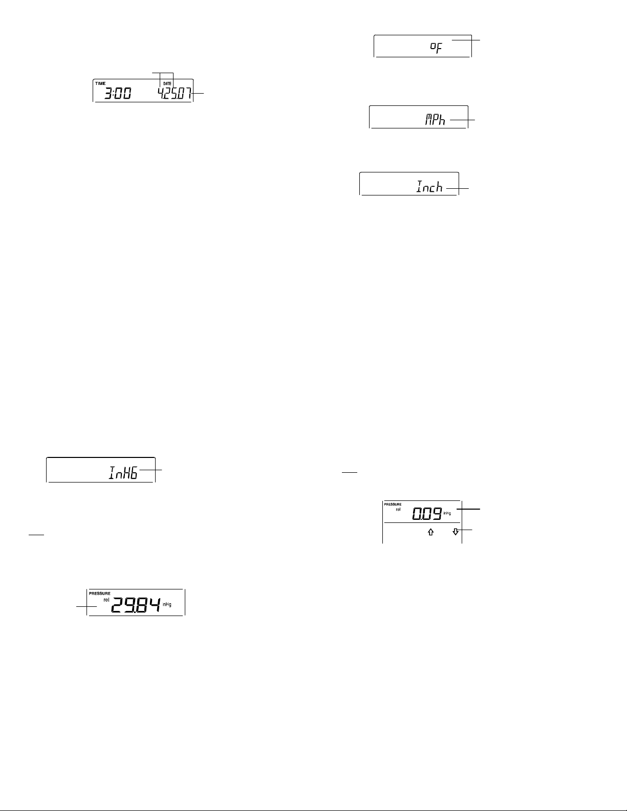
WEATHER TENDENCY SENSITIVITY LEVEL SETTING
You may select a definite switching sensitivity value, .06, .09, or .12 inHg for the change in the
display of weather icons. This represents the "sensitivity" of the weather forecast (the smaller the
value selected, the more sensitive the weather forecast). The default value is 0.09 inHg. Select
lower numbers for high humidity areas, i.e. Oceanside. Select high numbers for arid areas, i.e.
desert.
1. The sensitivity value will start flashing
2. Use the + or MIN/MAX key to select the value.
3. Confirm with the SET key and enter the STORM WARNING SENSITIVITY SETTING.
Flashing
Flashing
24
 Loading...