

g
p
y
Contents
Language Page
____________________________________________________________________________
English 1
French
Spanish
1
WIRELESS 915 MHz TEMPERATURE STATION
TABLE OF CONTENTS
Topic
Inventory of Contents
Features
Setting U
Battery Installation
Function keys
LCD Screen and Settings
Manual Settings
Display of Indoor Temperature
Display of Outdoor Temperature
Display of MIN/MAX OutdoorRecords
Reset of MIN/MAX records
Weather girl Icons (Temperature Condition Icons)
915 MHz Reception
Mounting
Care and Maintenance
Warranty Information
Instruction Manual
e
Pa
2
This product offers:
INVENTORY OF CONTENTS
1. Wireless Temperature Station
2. Wireless Temperature Sensor (TX40U-IT) and mounting bracket.
3. Instruction Manual
INSTANT TRANSMISSION is the state-of-the-art new wireless
transmission technology, exclusively designed and developed by
LA CROSSE TECHNOLOGY. INSTANT TRANSMISSION offers you
an immediate update (every 4 seconds!) of all your outdoor data
measured from the transmitters: follow your climatic variations in
real-time!
3
FEATURES:
Temperature station
The Temperature Station
Manual time setting (hour and minute display)
Time display 12 or 24-hour time format
Indoor and outdoor temperature reading in degree Fahrenheit (°F) or Celsius (°C)
Display MIN/MAX outdoor temperature
Display one of the 5 easy-to-read temperature condition icons featured by Weather Girl
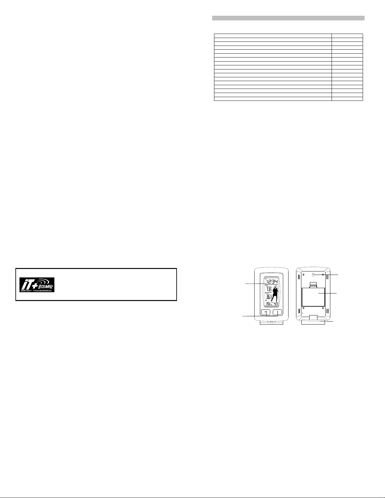
Displa
Function Keys
LCD
4
Hanging hole
Battery
compartment
Stand
Low battery indicator
y
Wireless transmission at 915 MHz
Signal reception intervals at 4 seconds
Wall mounting or table standing (removable table stand included)
The Outdoor Temperature Transmitter
SETTING UP:
Note: this temperature station can only receive one transmitter.
1. First, insert the batteries to the transmitter (see “How to install and replace batteries in the
Temperature transmitter” below).
Remote transmission of outdoor temperature to Temperature
Station by 915 MHz signals
Rain proof casing
Wall mounting and table-standing
Mounting at a sheltered place. Avoid direct rain and sunshine
2. Within 30 seconds of powering up the transmitter, insert the batteries to the Temperature Station
(see “How to install and replace batteries in the Temperature station” below). Once the
batteries are in place, all segments of the LCD will light up briefly. Following the indoor
temperature, the Weather Girl icon and the time as 12:00 will be displayed. If they are not shown
in LCD after 60 seconds, remove the batteries and wait for at least 60 seconds before
reinserting them. Once the indoor data is displayed user may proceed to the next step.
3. After the batteries are inserted, the Temperature Station will start receiving data signal from the
transmitter. The outdoor temperature should then be displayed on the Temperature station. If
this does not happen after 2 minutes, the batteries will need to be removed from both units and
reset from step 1.
4. In order to ensure sufficient 915 MHz transmission however, this should under good conditions
be a distance no more than 200 feet (60 meters) between the final position of the Temperature
Station and the transmitter (see notes on “Positioning” and “915 MHz Reception”).
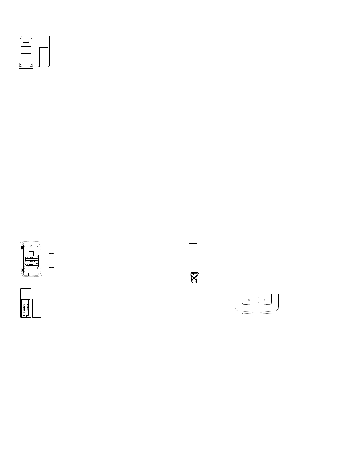
HOW TO INSTALL AND REPLACE BATTERIES IN THE TEMPERATURE STATION
The Temperature Station uses 3 x AA, IEC LR6, 1.5V batteries. When batteries will need to be
replaced, the low battery icon will appear on the LCD. To install and replace the batteries, please
follow the steps below:
5
1. Lift up the battery compartment cover.
2. Insert batteries observing the correct polarity (see marking).
HOW TO INSTALL AND REPLACE BATTERIES IN THE TEMPERATURE TRANSMITTER
The Temperature transmitter uses 2 x AAA, IEC LR3, 1.5V batteries. When
batteries will need to be replaced, the low battery icon will appear on the LCD of
the Temperature Station. To install and replace the batteries, please follow the
steps below:
1. Remove the battery compartment cover.
2. Insert the batteries, observing the correct polarity (see marking).
3. Replace the battery holder to the unit.
3. Replace compartment cover.
7
6
Note:
In the event of changing batteries in any of the units, all
procedures. This is because a random security code is assigned by the transmitter at start-up and this
code must be received and stored by the Temperature Station in the first few minutes of power
supplying.
BATTERY CHANGE:
It is recommended to replace the batteries in all units regularly to ensure optimum accuracy of these
units. (Battery life –see Specifications)
Please participate in the preservation of the environment. Return used batteries to an
authorized depot.
FUNCTION KEYS:
The Temperature Station has only two easy to use function keys.
SET ke
units need to be reset by following the setup
+ key
8
SET key
r
r
(
)
Press and hold for about 3 seconds to enter the Manual setting mode.
+ key
Press to make adjustment in the setting mode.
Press and hold to reset all MIN/MAX records
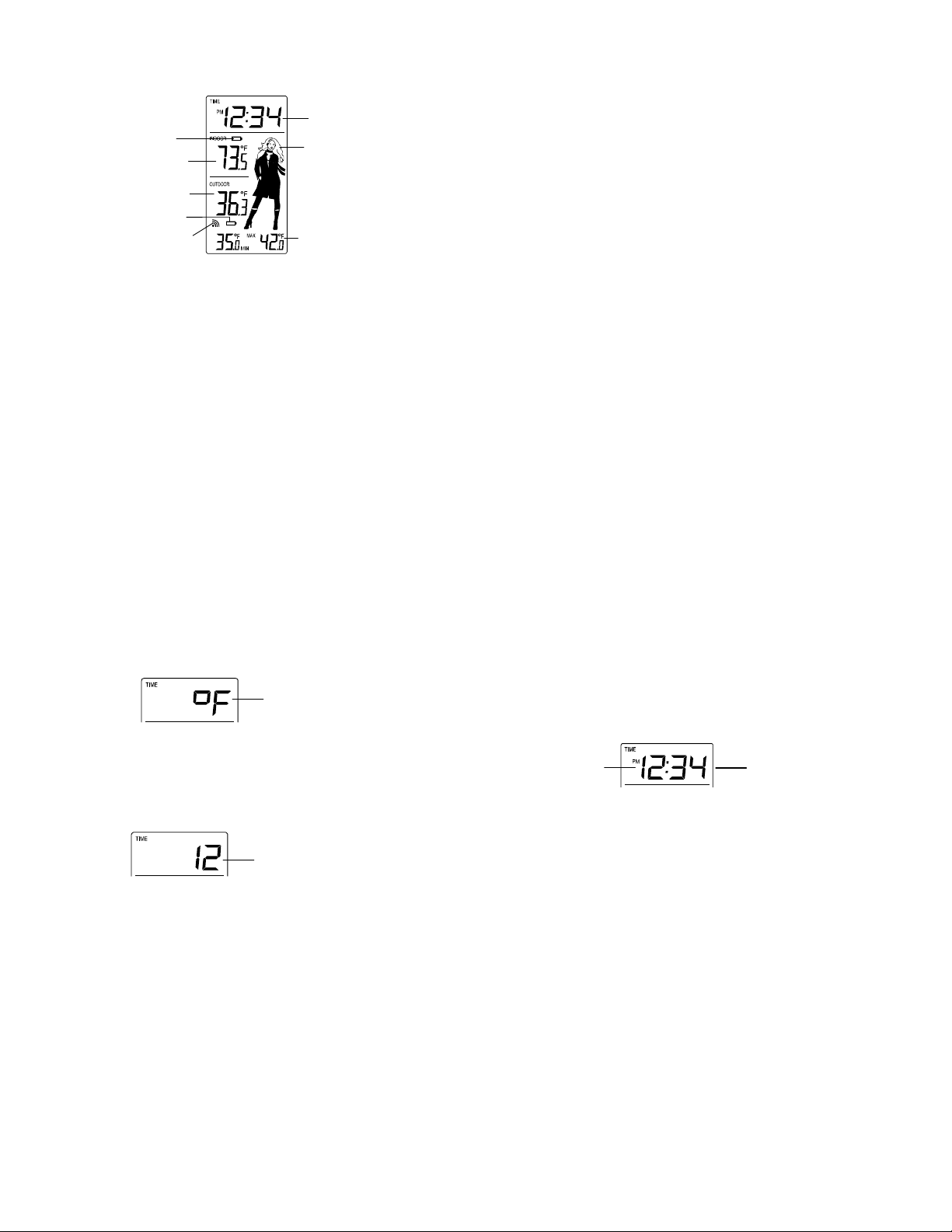
LCD SCREEN AND SETTINGS:
Low battery indicato
(temperature station)
Indoor Temperature
in °F/°C
Outdoor Temperature
in °F/°C
Low battery indicato
transmitter
Outdoor Reception
Signal icon*
9
Time
Temperature icon
(Weather Girl icon)
MIN/MAX Outdoor
temperature
* When the signal from the transmitter is successfully received by the Temperature Station, this icon
will be switched on. (If not successful, the icon will not be shown on the LCD). User can therefore
easily see whether the last reception was successful (“ON” icon) or not (“OFF” icon). On the other
hand, the short blinking of the icon shows that a reception is being done at that time.
For a better display clarity, the LCD screen is split into 3 sections.
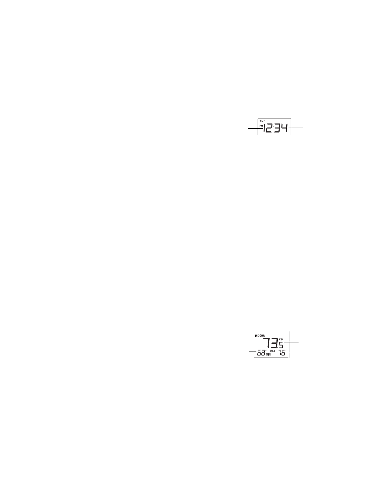
Section 1 - TIME
Display of time (manually set).
Section 2 - INDOOR TEMPERATURE
Display of indoor temperature.
Section 3 - CURRENT OUTDOOR TEMPERATURE AND MIN/MAX OUTDOOR TEMPERATURE
Display the current temperature.
Display the outdoor minimum and maximum temperature.
Display of the current temperature condition on the right side of the LCD in form of one of the
MANUAL SETTING:
In normal display, press and hold the SET key for 3 seconds to enter the manual setting mode.
AND WEATHER GIRL ICON
five weather icons (featured by Weather Girl) which change their appearance depending on the
current outdoor temperature.
10
F/C TEMPERATURE UNIT SETTING
The temperature can be set in F (degree Fahrenheit) or C (degree Celsius); default setting in F:
1. Press and hold the SET key in the normal display for about 3 seconds, the digit "F" will be
flashing.
2. Press the + key to select the unit as F or C.
3. Confirm by pressing the SET key to enter the 12/24 hour time display setting.
Note:
If no buttons are pressed within approximately 8 seconds while in any setting option, the unit will return
to normal operating mode.
12 / 24- HOUR TIME DISPLAY SETTING
The time format can be set in 12-hour or 24-hour mode (default setting “12”):
Flashing
Flashing
11
1. The "12" or "24" digit will be flashing.
2. Press the + key to set the desired time display mode.
3. Press shortly the SET key to advance to the MANUAL TIME SETTING.
Note:
If no buttons are pressed within approximately 8 seconds while in any setting option, the unit will return
to normal operating mode.
MANUAL TIME SETTING
To manually set the time of the Temperature Station:
Hour (flashing)
1. The hour digit of the time display will be flashing.
2. Press the + key to adjust the hour (press and hold to allow fast advance). Press SET key to
confirm and go to the minute setting.
3. The minute digit will be flashing. Press the + key to adjust the minute (press and hold to allow
fast advance). Press SET key once more to return to normal display.
Note:
If no buttons are pressed within approximately 8 seconds while in any setting option, the unit will return
to normal operating mode.
Minute s (flashing)
12

VIEWING THE INDOOR TEMPERATURE
The indoor temperature is displayed in the second section of the LCD:
Indoor temperature
VIEWING THE OUTDOOR TEMPERATURE AND MIN/MAX TEMPERATURE
The outdoor temperature is displayed in the last section of the LCD and the MIN/MAX outdoor
temperature is displayed below the outdoor temperature.
Outdoor temperature
MIN outdoor temperature
Note: The minimum/maximum temperature resolution is 0.5°F / 0.5°C.
MAX outdoor temperature
TO RESET THE MI N/MAX OUTDOO R DA TA:
The MIN/MAX outdoor temperature can be reset manually by pressing and holding the + key for about
3 seconds.
WEATHER GIRL ICON (Temperature condition icons):
One of the 5 different temperature icons (featured by weather girl with different clothing) is displayed in
the right side of the LCD, which indicates the different temperature conditions due to the current
outdoor temperature:
>78.8F 66.2 - 78.6 F 50 - 66F 32 – 49.8F < 32F
(>26C) (19 - 25.9C) (10 – 18.9C) (0 – 9.9C) (< 0C)
13
915 MHz RECEPTION CHECK
The Temperature Station should receive the outdoor temperature data within a few minutes after
setup. If the temperature data are not received about 2 minutes after setup (the signal reception icon
does not appear), please check the following points:
1. The distance of the Temperature Station or transmitter should be at least 5 to 6.5 feet (1.5 to 2
meters) away from any interfering sources such as computer monitors or TV sets.
2. Avoid positioning the Temperature Station onto or in the immediate proximity of metal window
frames.
3. Using other electrical products such as headphones or speakers operating on the same signal
frequency (915MHz) may prevent correct signal transmission and reception.
4. Neighbours using electrical devices operating on the 915MHz signal frequency can also cause
interference.
Note:
When the 915MHz signal is received correctly, do not re-open the battery cover of either the
transmitter or the Temperature Station, as the batteries may spring free from the contacts and force a
false reset. If this happens accidentally, all units must be reset (see Setting up above) otherwise
transmission problems may occur.
The transmission range is about 200 feet/ 60 m from the transmitter to the Temperature Station (in
open space). However, this depends on the surrounding environment and interference levels. If no
reception is possible despite the observation of these factors, all system units have to be reset (see
Setting up above).
15
14
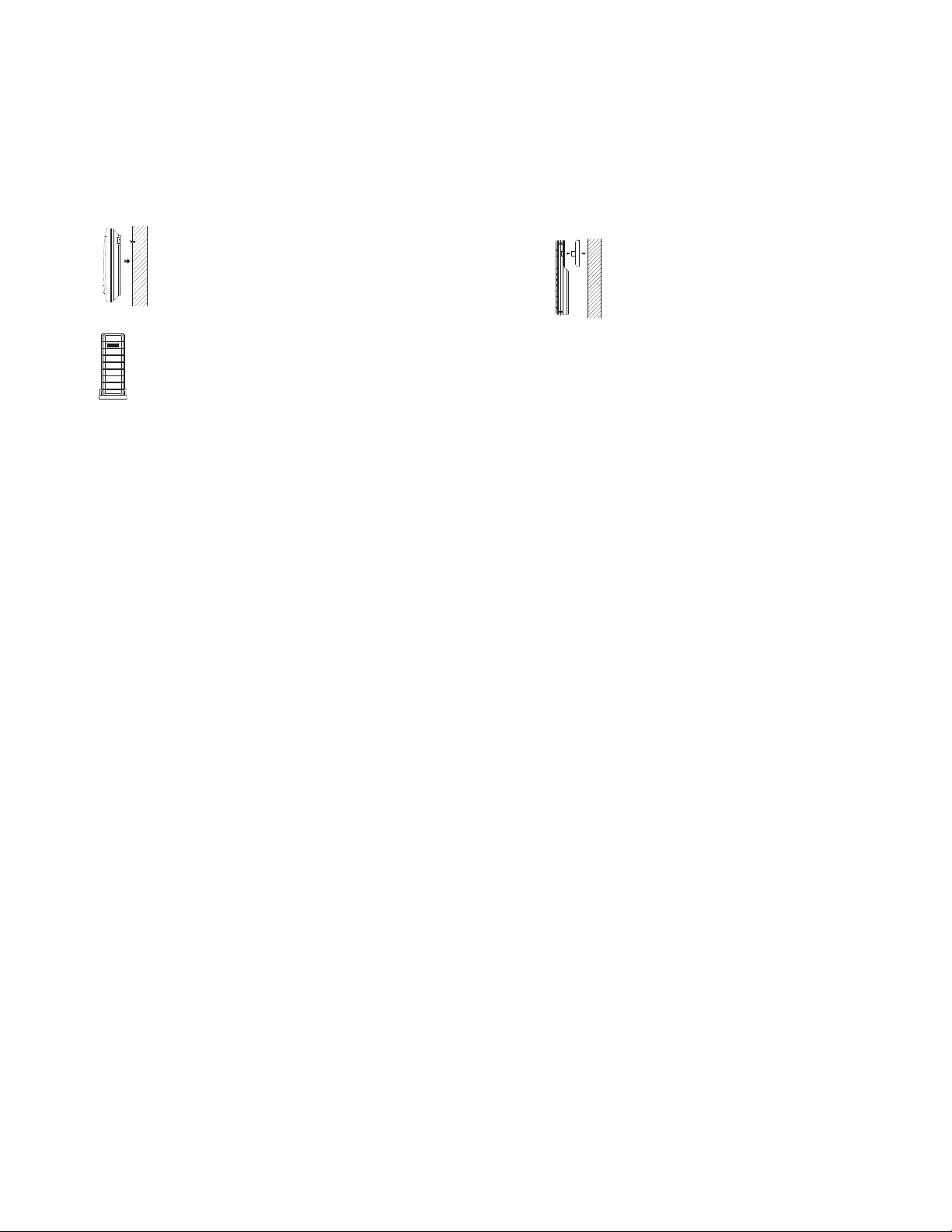
POSITIONING THE TEMPERATURE STATION:
The Temperature Station comes attached with a table stand, which provides the
option of table standing the unit in addition to wall mounting. Before wall
mounting, please check that the outdoor temperature values can be received
from the desired locations.
To wall mount:
1. Fix a screw (not supplied) into the desired wall, leaving the head extended
out by about 5mm.
2. Hang the Temperature Station onto the screw. Remember to ensure that it
locks into place before releasing.
16

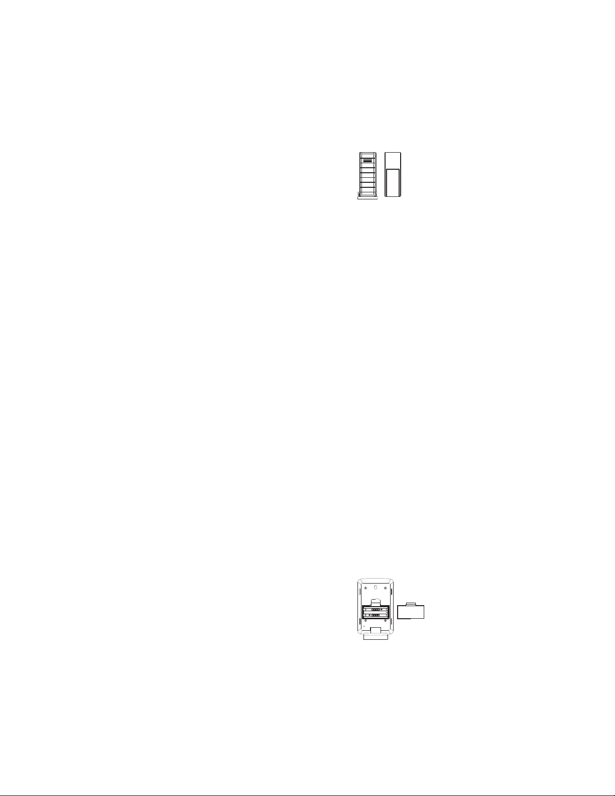
POSITIONING THE REMOTE TEMPERATURE TRANSMITTE R:
The remote temperature transmitter can be placed onto any flat surface or wall
mounted using the bracket which doubles as a stand or wall mount base.
To wall mount:
1. Secure the bracket onto a desired wall using the screws and plastic
anchors.
2. Clip the remote temperature transmitter onto the bracket.
Note:
The mounting surface can affect the transmission range. If, for instance, the unit
is attached to a piece of metal, it may then either reduce or increase the
transmitting range. For this reason, we recommend not to place the unit on any
metal surfaces or in any position where a large metal or highly polished surface
is in the immediate vicinity (garage doors, double glazing, etc.). Before securing
17
in place, please ensure that the Temperature Station can receive the 915MHz signal from the
temperature transmitter at the positions that you wish to place them.
CARE AND MAINTENANCE:
Extreme temperatures, vibrations and shocks should be avoided as these may cause damage to
the unit and give inaccurate forecasts and readings.
When cleaning the display and casings, use a soft damp cloth only. Do not use solvents or
scouring agents as they may mark the LCD and casings.
Do not submerge the units in water. Furthermore, fix all parts in place where the units are
adequately protected against moisture and rain.
Immediately remove all low powered batteries to avoid leakage and damage. Replace only with
new batteries of the recommended type.
Do not make any repair attempts to the unit. Return them to their original point of purchase for
repair by a qualified engineer. Opening and tampering with the unit may invalidate their
guarantee.
Do not expose the units to extreme and sudden temperature changes, this may lead to rapid
changes in forecasts and readings and thereby reduce their accuracy.
SPECIFICATIONS:
Temperature measuring range
Indoor : -3.8ºF to +139.8ºF with 0.2ºF resolution
(-19.9 to +59.9C with 0.1C resolution)
(“OF.L” displayed if outside this range)
18
Outdoor : -39.8ºF to +139.8ºF with 0.2ºF resolution
(-39.9 to +59.9C with 0.1C resolution)
(“OF.L” displayed if outside this range)
Indoor Temperature checking interval : every 20 seconds
Outdoor data checking interval : every 4 seconds
Power consumption
Temperature Station : 3 x AA, IEC LR6, 1.5V
Outdoor Temperature Transmitter : 2 x AAA, IEC LR3, 1.5V
Battery life cycle (Alkaline batteries recommended):
Temperature Station : approximately 24 months
Outdoor Temperature Transmitter : approximately 12 months
Dimensions (L x W x H)
Temperature Station : 3.58” x 1.14” x 5.90” / 91 x 29 x 150 mm
Outdoor Temperature Transmitter : 1.27" x 0.55" x 3.40" / 32.4mm x
WARRANTY
La Crosse Technology, Ltd provides a 1-year limited warranty on this product against manufacturing
defects in materials and workmanship.
This limited warranty begins on the original date of purchase, is valid only on products purchased and
used in North America and only to the original purchaser of this product. To receive warranty service,
the purchaser must contact La Crosse Technology, Ltd for problem determination and service
procedures. Warranty service can only be performed by a La Crosse Technology, Ltd authorized
19
14.1 x 86.5mm
service center. The original dated bill of sale must be presented upon request as proof of purchase to
La Crosse Technology, Ltd or La Crosse Technology, Ltd’s authorized service center.
La Crosse Technology, Ltd will repair or replace this product, at our option and at no charge as
stipulated herein, with new or reconditioned parts or products if found to be defective during the limited
warranty period specified above. All replaced parts and products become the property of La Crosse
Technology, Ltd and must be returned to La Crosse Technology, Ltd. Replacement parts and
products assume the remaining original warranty, or ninety (90) days, whichever is longer. La Crosse
Technology, Ltd will pay all expenses for labor and materials for all repairs covered by this warranty. If
necessary repairs are not covered by this warranty, or if a product is examined which is not in need or
repair, you will be charged for the repairs or examination. The owner must pay any shipping charges
incurred in getting your La Crosse Technology, Ltd product to a La Crosse Technology, Ltd authorized
service center. La Crosse Technology, Ltd will pay ground return shipping charges to the owner of the
product to a USA address only.
Your La Crosse Technology, Ltd warranty covers all defects in material and workmanship with the
following specified exceptions: (1) damage caused by accident, unreasonable use or neglect (including
the lack of reasonable and necessary maintenance); (2) damage occurring during shipment (claims
must be presented to the carrier); (3) damage to, or deterioration of, any accessory or decorative
surface; (4) damage resulting from failure to follow instructions contained in your owner’s manual; (5)
damage resulting from the performance of repairs or alterations by someone other than an authorized
La Crosse Technology, Ltd authorized service center; (6) units used for other than home use (7)
applications and uses that this product was not intended or (8) the products inability to receive a signal
20

due to any source of interference. This warranty covers only actual defects within the product itself,
and does not cover the cost of installation or removal from a fixed installation, normal set-up or
adjustments, claims based on misrepresentation by the seller or performance variations resulting from
installation-related circumstances.
LA CROSSE TECHNOLOGY, LTD WILL NOT ASSUME LIABILITY FOR INCIDENTAL,
CONSEQUENTIAL, PUNITIVE, OR OTHER SIMILAR DAMAGES ASSOCIATED WITH THE
OPERATION OR MALFUNCTION OF THIS PRODUCT. THIS PRODUCT IS NOT TO BE USED FOR
MEDICAL PURPOSES OR FOR PUBLIC INFORMATION. THIS PRODUCT IS NOT A TOY. KEEP
OUT OF CHILDREN’S REACH.
This warranty gives you specific legal rights. You may also have other rights specific to your State.
Some States do no allow the exclusion of consequential or incidental damages therefore the above
exclusion of limitation may not apply to you.
For warranty work, technical support, or information contact:
La Crosse Technology, Ltd
2809 Losey Blvd. S.
La Crosse, WI 54601
Phone: 608.782.1610
Fax: 608.796.1020
support@lacrossetechnology.com
sales@lacrossetechnology.com
(information on other products)
Question? Instructions? Please visit:
All rights reserved. This handbook must not be reproduced in any form, even in excerpts, or duplicated or
processed using electronic, mechanical or chemical procedures without written permission of the publisher.
This handbook may contain mistakes and printing errors. The information in this handbook is regularly
checked and corrections made in the next issue. We accept no liability for technical mistakes or printing errors,
or their consequences.
All trademarks and patents are acknowledged.
www.lacrossetechnology.com/9760
e-mail:
(warranty work)
www.lacrossetechnology.com
web:
21
22

Contents
g
y
Language Page
________________________________________________
English 1
French
Spanish
WIRELESS 915 MHz TEMPERATURE STATION
Instruction Manual
TABLE OF CONTENTS
Topic
Inventory of Contents
Features
Setting Up
Battery Installation
Function keys
LCD Screen and Settings
Manual Settings
Display of Indoor Temperature and MIN/MAX Records
Display of Outdoor Temperature and MIN/MAX Records
e
Pa
Reset of MIN/MAX records
915 MHz Reception
Mounting
Care and Maintenance
Warranty Information
INSTANT TRANSMISSIONis the state-of-
This product offers:
the-art new wireless transmission
technology, exclusively designed and
developed by LA CROSSE TECHNOLOGY.
INSTANT TRANSMISSION offers you a n
immediate update (every 4 seconds!) of all
your outdoor data measured from the
transmitters: follow your climatic variations
in real-time!
1
INVENTORY OF CONTENTS
1. W ireless Temperature Station
2. Wireless Temperature Sensor (TX40U-IT) and mounting bracket.
3. Instruction Manual
FEATURES:
Temperature station
LCD
Displa
Function
Keys
3
2
Hanging
hole
Battery
compartment
Stand
4
The Temperature Station
x Manual time setting (hour and minute display)
x Time display 12 -hour time format
x Indoor and outdoor temperature reading in degree Fahrenheit (°F)
x Display MIN/MAX indoor and outdoor temperature display
x Low battery indicator
x Wireless transmission at 915 MHz
x Signal reception intervals at 4 seconds
x Wall mounting or table standing
The Outdoor Temperature Transmitter
SETTING UP:
Note: this temperature station can only receive one transmitter only.
1. First, insert the batteries to the transmitter (see “How to install and
replace batteries in the Temperature transmitter” below).
2. Within 30 seconds of powering up the transmitter, insert the
x Remote transmission of outdoor temperature
to Temperature Station by 915 MHz signals
x Rain proof casing
x Wall mounting and table-standing
x Mounting at a sheltered place. Avoid
direct rain and sunshine
5
batteries to the Temperature Station (see “How to install and
replace batteries in the Temperature station” below). Once the
batteries are in place, all segments of the LCD will light up briefly.
Following the indoor temperature, the time as 12:00 will be
displayed. If they are not shown in LCD after 60 seconds, remove
the batteries and wait for at least 60 seconds before reinserting
them. Once the indoor data is displayed user may proceed to the
next step.
3. After the batteries are inserted, the Temperature Station will start
receiving data signal from the transmitter. The outdoor temperature
should then be displayed on the Temperature station. If this does
not happen after 2 minutes, the batteries will need to be removed
from both units and reset from step 1.
4. In order to ensure sufficient 915 MHz transmission however, this
should under good conditions be a distance no more than 200 feet
6
(60 meters) between the final position of the Temperature Station
and the transmitter (see notes on “Positioning” and “915 MHz
Reception”).
HOW TO INSTALL AND REPLACE BATTERIES IN THE
TEMPERATURE STATION
The Temperature Station uses 2 x AAA, IEC LR3, 1.5V batteries. When
batteries will need to be replaced, the low
battery icon will appear on the LCD. To
install and replace the batteries, please
follow the steps below:
1. Lift up the battery compartment cover.
2. Insert batteries observing the correct
polarity (see marking).
3. Replace compartment cover.
7
8

HOW TO INSTALL AND REPLACE BATTERIES IN THE
y
r
(
)
TEMPERATURE TRANSMITTER
Note:
In the event of changing batteries in any of the units, all units need to be
reset by following the setup procedures. This is because a random
The Temperature transmitter uses 2 x AAA, IEC
LR3, 1.5V batteries. When batteries will need to be
replaced, the low battery icon will appear on the
LCD of the Temperature Station. To install and
replace the batteries, please follow the steps
below:
1. Remove the battery compartment cover.
2. Insert the batteries, observing the correct
polarity (see marking).
3. Replace the battery holder to the unit.
security code is assigned by the transmitter at start-up and this code must
be received and stored by the Temperature Station in the first few minutes
of power supplying.
BATTERY CHANGE:
It is recommended to replace the batteries in all units regularly to ensure
optimum accuracy of these units. (Battery life –see Specifications)
Please participate in the preservation of the environment.
Return used batteries to an authorized depot.
FUNCTION KEYS:
The Temperature Station has only two easy to use function keys:
9
SET ke
SET key
x Press and hold for about 3 seconds to enter the Manual setting
mode.
+ key
x Press to make adjustment in the setting mode.
x Press and hold to reset all MIN/MAX records
+ key
11
LCD SCREEN AND SETTINGS:
Time
Indoor Temperature
Low battery indicato
Outdoor Temperature
in °F
transmitter
in °F
10
Low battery indicator
(temperature station)
MIN/MAX Indoor
temperature
Outdoor Reception
Signal icon*
MIN/MAX Outdoor
temperature
12
* When the signal from the transmitter is successfully received by the
r
Ʊ
Temperature Station, this icon will be switched on. (If not successful, the
icon will not be shown on the LCD). User can therefore easily see whether
the last reception was successful (“ON” icon) or not (“OFF” icon). On the
other hand, the short blinking of the icon shows that a reception is being
done at that time.
For a better display clarity, the LCD screen is split into 3 sections.
Section 1 - TIME
x Display of time (manually set).
Section 2 - CURRENT INDOOR TEMPERATURE AND MIN/MAX
x Display of indoor temperature.
x Display the indoor MIN/MAX temperature.
TEMPERATURE
Section 3 - CURRENT OUTDOOR TEMPERATURE MIN/MAX
x Display the current temperature.
x Display the outdoor MIN/MAX temperature.
MANUAL TIME SETTING:
To manually set the time of the Temperature Station:
Hour (flashing)
1. Press and hold the SET key for 3 seconds to enter the manual
2. The hour digit of the time display will be flashing.
TEMPERATURE
Minutes (flashing)
setting mode.
13
3. Press the + key to adjust the hour (press and hold to allow fast
advance). Press SET key to confirm and go to the minute setting.
4. The minute digit will be flashing. Press the + key to adjust the
minute (press and hold to allow fast advance). Press SET key once
more to return to normal display.
Note:
If no buttons are pressed within approximately 8 seconds while in any
setting option, the unit will return to normal operating mode.
VIEWING THE INDOOR TEMPERATURE AND MIN/MAX
The indoor temperature is displayed in the second section of the LCD
along with the indoor MIN/MAX records:
14
F.
Indoor temperature
MAX indoor
temperature
MIN indoo
temperature
Note:
x The maximum temperature record for the MIN indoor
temperature can only be up to 99ºF, and the MIN/MAX
temperature resolution is 1
x The resolution of the indoor temperature is 0.5ºF
15
16

r
VIEWING THE OUTDOOR TEMPERATURE AND THE MIN/ MAX
Ʊ
TEMPERATURE
The outdoor temperature is displayed in the last section of the LCD along
with the outdoor MIN/MAX records:
Outdoor temperature
MIN outdoo
Note:
x The minimum/maximum temperature resolution is 1
x The resolution of the outdoor temperature is 0.1ºF
temperature
MAX outdoor
temperature
F.
TO RESET THE MIN/MAX DATA:
The MIN/MAX temperature can be reset manually by pressing and holding
the + key for about 3 seconds. This will reset all indoor and outdoor
MIN/MAX temperature to current indoor and outdoor temperatures.
915 MHz RECEPTION CHECK
The Temperature Station should receive the outdoor temperature data
within a few minutes after setup. If the temperature data are not received
about 2 minutes after setup (the signal reception icon does not appear),
please check the following points:
1. The distance of the Temperature Station or transmitter should be at
least 5 to 6.5 feet (1.5 to 2 meters) away from any interfering
sources such as computer monitors or TV sets.
2. Avoid positioning the Temperature Station onto or in the immediate
proximity of metal window frames.
3. Using other electrical products such as headphones or speakers
17
operating on the same signal frequency (915MHz) may prevent
correct signal transmission and reception.
4. Neighbors using electrical devices operating on the 915MHz signal
frequency can also cause interference.
Note:
When the 915MHz signal is received correctly, do not re-open the battery
cover of either the transmitter or the Temperature Station, as the batteries
may spring free from the contacts and force a false reset. If this happens
accidentally, all units must be reset (see Setting up above) otherwise
transmission problems may occur.
The transmission range is about 200 feet / 60 m from the transmitter to the
Temperature Station (in open space). However, this depends on the
surrounding environment and interference levels. If no reception is
possible despite the observation of these factors, all system units have to
be reset (see Setting up above).
18
POSITIONING THE TEMPERATURE STATION:
The Temperature Station comes attached with a
table stand, which provides the option of table
standing the unit in addition to wall mounting.
19
20
To wall mount:
Before wall mounting, please check that the outdoor
temperature values can be received from the desired
locations:
1. Fix a screw (not supplied) into the desired wall,
leaving the head extended out by about 5mm.
2. Hang the Temperature Station onto the screw.
Remember to ensure that it locks into place before
releasing.
POSITIONING THE REMOTE TEMPERATURE TRANSMITTER:
The remote temperature transmitter can be placed onto any
flat surface or wall mounted using the bracket which doubles
as a stand or wall mount base.
To wall mount:
range. For this reason, we recommend not to place the unit on any metal
surfaces or in any position where a large metal or highly polished surface
is in the immediate vicinity (garage doors, double glazing, etc.). Before
securing in place, please ensure that the Temperature Station can receive
the 915MHz signal from the temperature transmitter at the positions that
you wish to place them.
1. Secure the bracket onto a desired wall using the
screws and plastic anchors.
2. Clip the remote temperature transmitter onto the
bracket.
Note:
The mounting surface can affect the transmission range.
If, for instance, the unit is attached to a piece of metal, it
may then either reduce or increase the transmitting
21
CARE AND MAINTENANCE:
x Extreme temperatures, vibrations and shocks should be avoided as
these may cause damage to the unit and give inaccurate forecasts
and readings.
x When cleaning the display and casings, use a soft damp cloth only.
Do not use solvents or scouring agents as they may mark the LCD
and casings.
x Do not submerge the units in water. Furthermore, fix all parts in
place where the units are adequately protected against moisture
and rain.
x Immediately remove all low powered batteries to avoid leakage and
damage. Replace only with new batteries of the recommended
type.
x Do not make any repair attempts to the unit. Return them to their
original point of purchase for repair by a qualified engineer.
22
Opening and tampering with the unit may invalidate their
guarantee.
x Do not expose the units to extreme and sudden temperature
changes, this may lead to rapid changes in forecasts and readings
and thereby reduce their accuracy.
SPECIFICATIONS:
Temperature measuring range
Indoor : -3.8.ºF to +139.8ºF with 0.5ºF resolution
(“OF.L” displayed if outside this range)
Outdoor : -39.8ºF to +139.8ºF with 0.1ºF resolution
(“OF.L” displayed if outside this range)
Indoor Temperature checking interval : every 20 seconds
Outdoor data checking interval : every 4 seconds
Power consumption
Temperature Station : 2 x AAA, IEC LR3, 1.5V
23
24

Outdoor Temperature Transmitter : 2 x AAA, IEC LR3, 1.5V
Battery life cycle (Alkaline batteries recommended):
Temperature Station : approximately 12 months
Outdoor Temperature Transmitter : approximately 12 months
Dimensions (L x W x H)
Temperature Station : 2.69” x 0.94” x 4.29” /
68.4 x 24.1 x 109 mm
Outdoor Temperature Transmitter : 1.27" x 0.55" x 3.40" /
32.4mm x 14.1 x 86.5mm
WARRANTY
La Crosse Technology, Ltd provides a 1-year limited warranty on this
product against manufacturing defects in materials and workmanship.
This limited warranty begins on the original date of purchase, is valid only
on products purchased and used in North America and only to the original
purchaser of this product. To receive warranty service, the purchaser
must contact La Crosse Technology, Ltd for problem determination and
service procedures. Warranty service can only be performed by a La
Crosse Technology, Ltd authorized service center. The original dated bill
of sale must be presented upon request as proof of purchase to La Crosse
Technology, Ltd or La Crosse Technology, Ltd’s authorized service center.
La Crosse Technology, Ltd will repair or replace this product, at our option
and at no charge as stipulated herein, with new or reconditioned parts or
products if found to be defective during the limited warranty period
specified above. All replaced parts and products become the property of
La Crosse Technology, Ltd and must be returned to La Crosse
Technology, Ltd. Replacement parts and products assume the remaining
original warranty, or ninety (90) days, whichever is longer. La Crosse
Technology, Ltd will pay all expenses for labor and materials for all repairs
covered by this warranty. If necessary repairs are not covered by this
warranty, or if a product is examined which is not in need or repair, you
25
will be charged for the repairs or examination. The owner must pay any
shipping charges incurred in getting your La Crosse Technology, Ltd
product to a La Crosse Technology, Ltd authorized service center. La
Crosse Technology, Ltd will pay ground return shipping charges to the
owner of the product to a USA address only.
Your La Crosse Technology, Ltd warranty covers all defects in material
and workmanship with the following specified exceptions: (1) damage
caused by accident, unreasonable use or neglect (including the lack of
reasonable and necessary maintenance); (2) damage occurring during
shipment (claims must be presented to the carrier); (3) damage to, or
deterioration of, any accessory or decorative surface; (4) damage resulting
from failure to follow instructions contained in your owner’s manual; (5)
damage resulting from the performance of repairs or alterations by
someone other than an authorized La Crosse Technology, Ltd authorized
service center; (6) units used for other than home use (7) applications and
26
uses that this product was not intended or (8) the products inability to
receive a signal due to any source of interference. This warranty covers
only actual defects within the product itself, and does not cover the cost of
installation or removal from a fixed installation, normal set-up or
adjustments, claims based on misrepresentation by the seller or
performance variations resulting from installation-related circumstances.
LA CROSSE TECHNOLOGY, LTD WILL NOT ASSUME LIABILITY FOR
INCIDENTAL, CONSEQUENTIAL, PUNITIVE, OR OTHER SIMILAR
DAMAGES ASSOCIATED WITH THE OPERATION OR MALFUNCTION
OF THIS PRODUCT. THIS PRODUCT IS NOT TO BE USED FOR
MEDICAL PURPOSES OR FOR PUBLIC INFORMATION. THIS
PRODUCT IS NOT A TOY. KEEP OUT OF CHILDREN’S REACH.
This warranty gives you specific legal rights. You may also have other
rights specific to your State. Some States do no allow the exclusion of
27
28

consequential or incidental damages therefore the above exclusion of
limitation may not apply to you.
For warranty work, technical support, or information contact:
La Crosse Technology, Ltd
2809 Losey Blvd. S.
La Crosse, WI 54601
Phone: 608.782.1610
Fax: 608.796.1020
support@lacrossetechnology.com
sales@lacrossetechnology.com
(information on other products)
e-mail:
(warranty work)
www.lacrossetechnology.com
Question? Instructions? Please visit:
www.lacrossetechnology.com/9240
All rights reserved. This handbook must not be reproduced in any form, even in
excerpts, or duplicated or processed using electronic, mechanical or chemical
procedures without written permission of the publisher.
This handbook may contain mistakes and printing errors. The information in this
handbook is regularly checked and corrections made in the next issue. We
accept no liability for technical mistakes or printing errors, or their consequences.
All trademarks and patents are acknowledged.
web:
29
FCC ID: OMO-TX40U (transmitter)
FCC DISCLAIMER
RF Exposure mobile:
The internal / external antennas used for this mobile transmitter must
provide a separation distance of at least 20 cm (8 inches) from all persons
and must not be co-located or operating in conjunction with any other
antenna or transmitter."
Statement according to FCC part 15.19:
This device complies with Part 15 of the FCC Rules. Operation is subject
to the following two conditions: (1) this device may not cause harmful
interference, and (2) this device must accept any interference received,
including interference that may cause undesired operation.
30
Statement according to FCC part 15.21:
Modifications not expressly approved by this company could void the
user's authority to operate the equipment.
Statement according to FCC part 15.105:
NOTE: This equipment has been tested and found to comply with the
limits for a Class B digital device, pursuant to Part 15 of the FCC Rules.
These limits are designed to provide reasonable protection against
harmful interference in a residential installation. This equipment
generates, uses and can radiate radio frequency energy and, if not
installed and used in accordance with the instructions, may cause harmful
interference to radio communications.
However, there is no guarantee that interference will not occur in a
particular installation. If this equipment does cause harmful interference to
radio or television reception, which can be determined by turning the
31
32

equipment off and on, the user is encouraged to try to correct the
interference by one or more of the following measures:
x Reorient or relocate the receiving antenna.
x Increase the separation between the equipment and receiver.
x Connect the equipment into an outlet on a circuit different from that
to which the receiver is connected.
x Consult the dealer or an experienced radio/TV technician for help.
33
 Loading...