

Page 1
Rev. 1.0.0
Item no. OM-IPD
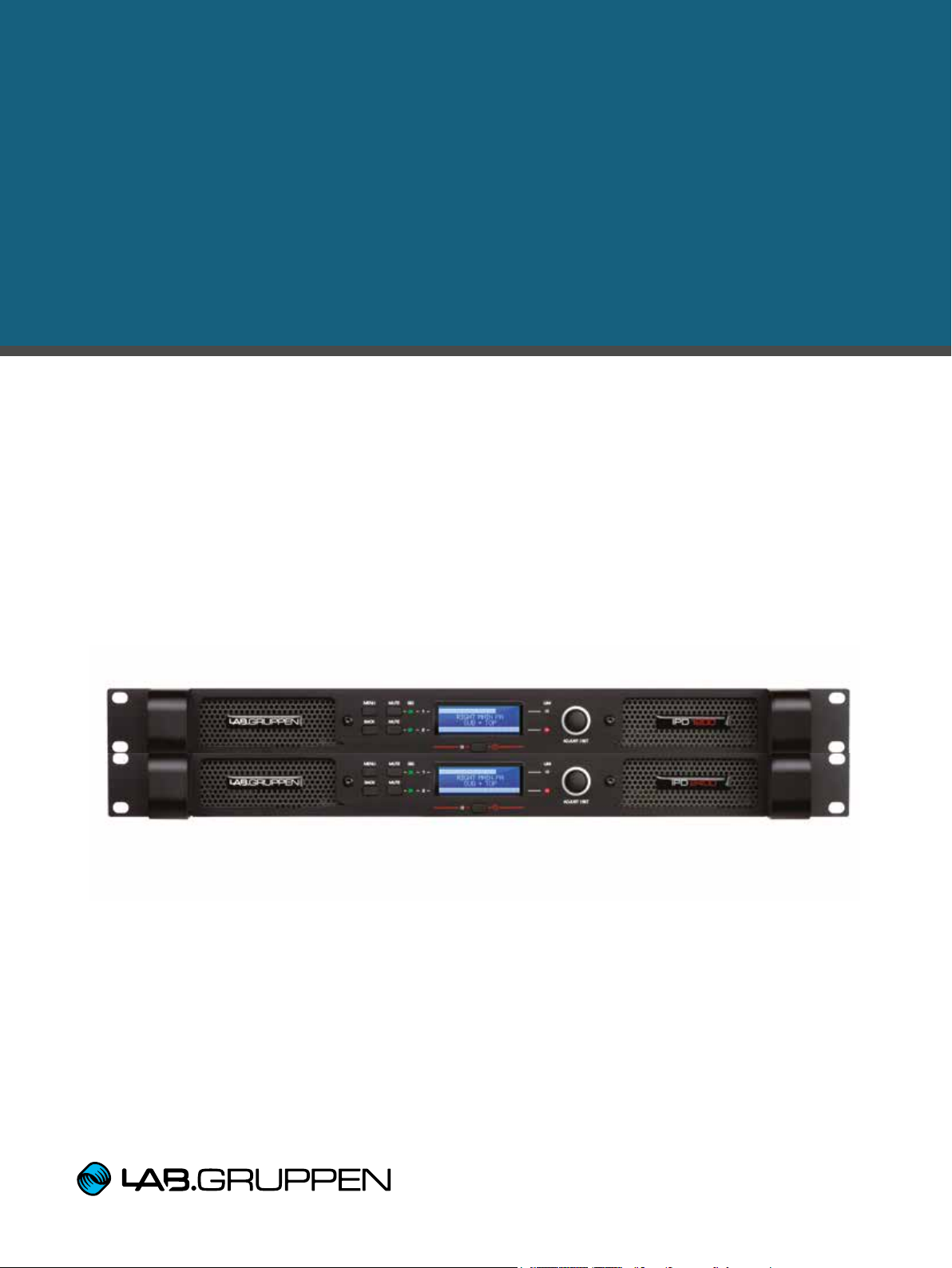
IPD SERIES
Touring and Installation Amplifiers
Operation Manual
Page 2
Important Safety Instructions
Important safety instructions
Before using your IPD Series, be sure to carefully read the applicable items of this Operation Manual and the Safety
Instructions.
1. Read these instructions.
2. Keep these instructions.
3. Heed all warnings.
4. Follow all instructions.
5. Do not use this apparatus near water.
6. Clean only with a dry cloth.
7. Do not block any ventilation openings. Install in accordance
with the manufacturer’s instructions.
8. Do not install near any heat sources such as radiators, heat
registers, stoves, or other apparatus (including ampliers)
that produce heat.
9. Do not defeat the safety purpose of the polarized or
grounding-type plug. A polarized plug has two blades with
one wider than the other. A grounding-type plug has two
blades and a third grounding prong. The wide blade or
the third prong is provided for your safety. If the provided
plug does not t into your outlet, consult an electrician for
replacement of the obsolete outlet.
10. Protect the power cord from being walked on or pinched,
particularly at plugs, convenience receptacles, and the point
where they exit from the apparatus.
11. Only use attachments/accessories specied by the
manufacturer.
12. Use only with a cart, stand, tripod, bracket, or table specied
by the manufacturer, or sold with the apparatus. When a
cart is used, use caution when moving the cart/apparatus
combination to avoid injury from tip-over.
13. Unplug this apparatus during lightning storms or when
unused for long periods of time.
14. Refer all servicing to qualied service personnel. Servicing
is required when the apparatus has been damaged in any
way, such as power-supply cord or plug is damaged, liquid
has been spilled or objects have fallen into the apparatus,
the apparatus has been exposed to rain or moisture, does
not operate normally, or has been dropped.
15. WARNING: To reduce the risk of re of electric shock, do not
expose this apparatus to rain or moisture.
16. Do not expose this equipment to dripping or splashing and
ensure that no objects lled with liquids, such as vases, are
placed on the equipment.
17. Do not connect the unit’s output to any other voltage
source, such as battery, mains source, or power supply,
regardless of whether the unit is turned on or off.
18. Do not remove the top (or bottom) cover. Removal of the
cover will expose hazardous voltages. There are no user
serviceable parts inside and removal may void the warranty.
19. An experienced user shall always super vise this professional
audio equipment, especially if inexperienced adults or
minors are using the equipment.
Standards
This equipment conforms to the requirements
of the EMC Directive 2004/108/EC and the
requirements of the Low Voltage Directive
2006/95/EC.
Standards applied: EMC Emis sion EN551031, E3
EMC Immunity EN55103-2, E3, with S/N below
1% at normal operation level.
Electrical Safet y EN60065, Class I
This equipment is tested and listed acc ord ing to the
U.S. safety standard ANSI/ UL 60065 and Canadian safety standard CSA C22.2 NO. 60065.
UL made the tests and they are a Nationally
Recognized Testing Laboratory (NRTL).
Warnings
Explanation of warning symbols
The lightning bolt triangle is used to
alert the user to the presence of
un-insulated “dangerous voltages”
within the unit’s chassis that may be
of sufcient magnitude to constitute a
risk of electric shock to humans.
The exclamation point triangle is used to
alert the user to presence of important
operating and service instructions in the
literature accompanying the product.
IPD SERIES Operation Manual rev 1.0.0
2
Page 3

Important Safety Instructions
Warnings
To reduce risk of re or electric shock, do not expose this
apparatus to rain or moisture.
Français: Pour réduire les risques d’incendie ou de choc
électrique, n’exposez pas l’appareil à la pluie ou à l’humidité.
Do not expose this system/apparatus to dripping or splashing
and ensure that no objects lled with liquids, such as vases,
are placed on the apparatus.
Français: N’exposez pas ce système/appareil au
ruissellement ni aux éclaboussures et assurez-vous qu’aucun
objet contenant du liquide tel qu’un vase n’est placé sur
l’appareil.
This apparatus must be connected to a mains socket outlet
with a protective earthing connection.
Français: Cet appareil doit être raccordé à une prise secteur
avec terre de protection.
The mains plug is used as a disconnect device and shall
remain readily operable.
Français: La che d’alimentation sert de dispositif de
déconnexion et doit rester constamment accessible.
To prevent electric shock do not remove top or bottom covers.
No user serviceable parts inside. Refer servicing to qualied
service personnel.
Français: Pour prévenir un choc électrique, ne retirez pas
les capots du dessus et du dessous. Aucune pièce n’est
réparable par l’utilisateur à l’intérieur. Conez toute réparation
à un personnel de maintenance qualié.
To completely disconnect this equipment from the AC mains,
disconnect the power supply cord plug from the ac receptacle.
The mains plug of the power supply cord shall remain readily
operable.
Français: Pour totalement isoler l’équipement de l’alimentation
secteur, débranchez le cordon d’alimentation de son
embase. La che secteur du cordon d’alimentation doit rester
accessible.
Radio interference
A sample of this product has been tested and complies with
the limits for the European Electro Magnetic Compatibility
(EMC) directive. It also has been tested and found to comply
with the limits for a Class A digital device, pursuant to Part
15 of the FCC Rules. These limits are designed to provide
reasonable protection against harmful interference from
electrical equipment. This product uses radio frequency
energy and, if not used or installed in accordance with these
operating instructions, may cause interference to other
equipment, such as radio receivers. However, there is no
guarantee that interference will not occur in a par ticular
installation. If this equipment causes harmful interference
to radio or television reception (determined by turning the
equipment on and off), the user may be able to correct the
interference by one or more of the following measures:
• Check if the affected unit complies with the EMC limits for
immunity, (CE-labeled). If not, address the problem with
the manufacturer or supplier. All electrical products
sold in the EC must be approved for immunity against
electromagnetic elds, high voltage ashes, and radio
interference.
• Consult the dealer or an experienced radio/TV technician
for help.
• Reorient or relocate the antenna.
• Increase the separation between the equipment and
re c eive r.
For customers in Canada
This Class B digital apparatus complies with Canadian ICES-003.
Français: Cet appareil numérique de la classe B est conforme
à la norme NMB003 du Canada.
IPD SERIES Operation Manual rev 1.0.0
3
Page 4

Table of Contents
Table of Contents
1. Introduction 6
1.1. Welcome 6
1.2. Features 7
2. Front panel 8
3. Rear panel 9
4. Signal ow block diagram 10
5. Amplier installation 10
5.1. Unpacking and visual check 10
5.2. Rack installation 10
5.3. Cooling requirements 10
6. Amplier connections 11
6.1. AC line input / operating voltage 11
6.2. Audio inputs 11
6.3. Loudspeaker connections 12
6.4. Network connection and conguration (optional) 12
6.5. Network conguration 14
7. IPD Controller software installation and network conguration 14
7.1. Downloading the installation folder 14
7.2. Windows software installation 14
7.3. Mac software installation 15
7.4. iPad App download and installation 15
8. Operation with default preset 16
9. IntelliDrive controller overview 16
9.1. Introduction 16
9.2. Global (System) View 16
9.3. Global (System) Menus 18
9.4. Mixer (Unit) View 18
IPD SERIES Operation Manual rev 1.0.0
4
Page 5

Table of Contents
10. IntelliDrive Controller Set-up and DSP Conguration 20
10.1. Setting up and modifying amplier groups 20
10.2. Device (Amplier) Set-Up 21
10.3. Input mixing 21
10.4. Level, limiter and channel link setting 21
10.5. Input EQ and delay setting 22
10.6. Output EQ and delay setting 23
10.7. Crossover conguration 23
10.8. Preset store and recall 23
11. Updating amplier rmware 24
12. Operation with iPad App 24
13. Third party control 25
14. Operation using front panel controls 25
14.1. Introduction 25
14.2. Overview of procedures 25
15. Appendices 26
15.1. Front-panel menu tree 26
15.2. Thermal dissipation charts 27
15.3. Technical specications 29
16. Warranty 31
17. Service 32
IPD SERIES Operation Manual rev 1.0.0
5
Page 6

1. Introduction
1. Introduction
1.1. Welcome
Thank you for choosing a Lab.gruppen IPD Intelligent Power Drive professional audio amplier. This manual
provides a comprehensive guide to the features and functionality of IPD 1200 and IPD 2400 ampliers. Please read
through this manual in its entirety to become fully acquainted with installation, connections, networking features,
DSP conguration options and protection circuitry.
To facilitate timely installation and use, the printed Quick Start Guide (included with the amplier) contains the
basic information needed to safely install and connect the amplier and place it in service. However, we highly
recommend reading through this manual in its entirety, beginning with Overview and continuing through the
specic details of network and DSP preset conguration. As you become thoroughly familiar with all aspects of
operation, you may learn of features or options that will affect your choices on amplier modes or loudspeaker
system conguration.
The extraordinary exibility of Lab.gruppen IPD Series power ampliers makes them adaptable to a wide range
of portable and permanent installation applications. IPD Series ampliers are an ideal choice for touring bands
and corporate AV presentation systems, where high power density and quick reconguration for multiple system
applications are of paramount importance. At the same time, the IPD Series ampliers are a cost-effective choice
for permanent installations in houses of worship, clubs, theatres and performing arts centres.
Although competitively priced, IPD Series ampliers draw on the foundational engineering that has made
Lab.gruppen the benchmark of quality for premier touring concert systems worldwide: exceptional sonic
performance, rugged construction, proven reliability, and protection features that anticipate every unwelcome
possibility.
This manual was created for the IPD Series IPD 1200 and IPD 2400 amplier models. All references to “IPD Series”
in this manual apply to both models.
IPD SERIES Operation Manual rev 1.0.0
6
Page 7

1.2. Features
• High power density with up to 2400 W in 1 U
• Two models: 2 × 600 W or 2 × 1200 W (at 4 ohms)
• Low mains current draw with proven IDEEA® technology
• AES3 and analog inputs with redundant failover
• Link outputs for analog and AES3
• Ethernet network connection
• Fast network setup with auto-discovery and ID of ampliers
• Networked control via IntelliDrive Controller™ software with touchscreen-friendly GUI
• Wireless control via iPad (requires connection of WiFi router)
• Four-channel input mixer
• Integrated DSP includes:
• 40 real-time, multi-slope parametric equalizers
• Adjustable high-pass and low-pass lters
• Input delay (up to 2 s)
• Output delay (up to 2 s)
• Crossover with multiple lter types
• 100 user-denable presets
• Backlit display with navigation buttons and encoder for front panel setup
• Horizontal VU meters on display in operating mode
• Front-panel mute buttons
• Software congurable limiters (SCVPL)
• Binding post and Neutrik speakON connectors
• Outputs may be connected through either one (NL-4) or both speakONs
• Universal power supply: 100 - 240 V at 50 or 60 Hz
• Three year warranty
1. Introduction
IPD SERIES Operation Manual rev 1.0.0
7
Page 8

2. Front panel
2. Front panel
1
2
The following indicators and controls are available on the front panel:
1 MENU - Selects MENU mode and conrms a given preset name.
2 BACK - Moves backward through menu layers in MENU mode.
3 MUTE - Mutes corresponding channel as indicated.
4 SIG - Illuminates green when signal is present. Illuminates red when signal is clipping (pre input mixer).
5 POWER - LED indicates STANDBY (red); off when amplier is ON.
6 LIM (limit) - Illuminates when the amplier limits the signal. Limiting is engaged when the channel:
• Reaches the selected voltage limit
• Rail voltage sags below the selected threshold (both LEDs ash rapidly for 1.5 sec)
• Maximum current output reached
• Mains voltage cannot maintain full rail voltage
3
4
6 78
5
7 ADJUST/SET (Rotary Encoder) - Rotation moves through the menu and adjusts the currently selected
parameter when in setup mode. Pressing down on the knob selects a given parameter or advances further into
the menu. In operating mode, rotation of the ADJUST/SET encoder adjusts output gain (outputs ganged).
8 BACKLIT DISPLAY - In operating mode, the display shows the following values and status indicators:
• Level - Horizontal VU meters for each channel
• Device name and Preset name
In setup mode, the display shows the currently selected menu locations and parameters. For more information on
DSP setup procedures, please refer to Section 10: IntelliDrive Controller Set-up and DSP Conguration.
IPD SERIES Operation Manual rev 1.0.0
8
Page 9

3. Rear panel
3. Rear panel
1 2
3 4
The following indicators and controls are available on the rear panel:
1 ANALOG INPUTS and LINK - XLR-F input connectors provided for each channel, with XLR-M link
output connectors.
2 AES3 INPUT and LINK - AES3 digital inputs are on an XLR-F connector with a link output on an
XLR-M connector.
3 NETWORK (Ethernet) - An RJ45 jack is supplied for connection to an Ethernet network for external control
and monitoring, either by a direct wired connection or via an external WiFi router to an iPad or tablet.
LEDs below the connector indicate valid network connection (LINK) and network activity (ACT).
When several IPDs are connected to a network, a switch with a built-in DHCP server should be used.
4 speakON OUTPUT CONNECTORS - Both channel outputs are available on a four-pole connector at the left;
either channel 1 or both channels 1 and 2 may be connected. Only channel 2 is available on the connector to
the right.
5
6
5 BINDING POST CONNECTORS - Connectors for channel 1 and channel 2.
6 AC LINE INPUT - A locking IEC receptacle accepts the AC line input at 50 Hz or 60 Hz, 100 V - 240 V.
Use an IEC cable with the proper connector for country of use.
IPD SERIES Operation Manual rev 1.0.0
9
Page 10

4. Signal flow block diagram
Analog 1
Analog 2
AES 1
AES 2
Input 1
Levels
Input 1
EQ
Input 1
delay
Output 1
Levels
Output 1
EQ
IDEEA
Amplifier
Output 1
Delay
Clip Limiter
Clip Limiter
Rail Sense Limiter
SCVPLX-Over
Input 2
Levels
Input 2
EQ
Input 2
delay
Output 2
Levels
Output 2
EQ
IDEEA
Amplifier
PSU
Output 2
Delay
SCVPLX-Over
Input
Mixer
4. Signal flow block diagram
The below diagram shows the signal ow from inputs to outputs:
5. Amplifier installation
5.1. Unpacking and visual check
Every Lab.gruppen amplier is carefully tested and inspected before leaving the factory and should arrive in perfect
condition. If any damage is discovered, please notify the shipping carrier immediately. Save the packing materials
for the carrier’s inspection and for any future shipping.
5.2. Rack installation
IPD 1200 - Depth is 272 mm (10.7”) rack ear to back panel. Weight is approximately 4.6 kg (10.1 lbs).
Rear support brackets are included and use is recommended in all applications.
IPD 2400 - Depth is 360 mm (14.2”) rack ear to back panel. Weight is approximately 6.2 kg (13.7 lbs).
Rear support brackets are included and use is recommended in all applications.
5.3. Cooling requirements
Please ensure that there is sufcient space in the front and the rear of each amplier to allow for a free ow of
air. No doors or covers should be mounted either in the front or rear of the ampliers. Ampliers may be stacked
directly on top of each other with no spacing, though some spacing may enable more convenient installation of
rear cabling. Refer to the Thermal Dissipation charts in Section 15.2 for thermal dissipation values when installing
large numbers of ampliers in enclosed spaces.
IPD SERIES Operation Manual rev 1.0.0
10
Page 11

6. Amplifier connections
6. Amplifier connections
6.1. AC line input / operating voltage
All IPD Series ampliers have a universal power supply that operates on mains from 100 - 240 V at 50 or
60 Hz. The IEC receptacle on the rear panel accepts the supplied IEC cord which terminates in a connector plug
appropriate for the country of sale. When AC power is connected, the amplier goes into standby (red indication
on standby LED). The amplier may be turned on by pressing the front power button or remotely using the
IntelliDrive Controller software.
Signal ground is oating via a resistor to chassis, and therefore grounding is automatic. For safety reasons,
never disconnect the earth (ground) pin on the AC power cord. Use balanced input connections to avoid hum
and interference.
6.2. Audio inputs
Analog inputs - Analog inputs are available on two standard XLR-F latching connectors. The inputs are
electronically balanced. The impedance is 20 kohms, and the inputs can accept a maximum input level of
+26 dBu. Polarity is as follows:
Pin 1 = screen (shield), pin 2 = positive (+), pin 3 = negative (-).
Analog links - Two latching XLR-M connectors are tted adjacent to the analog input connectors and are
paralleled to the respective input connectors; they provide an unprocessed analog loop-through signal to feed
additional IPD Series units or other equipment.
AES3 inputs - A latching XLR-F connector accepts an AES3 digital audio signal. Input impedance is 110 ohms.
Ensure that 110 ohm digital audio cables are used; standard XLR microphone cables are rarely suitable for reliable
digital audio transmission.
Note: AES3 is a stereo digital format, and therefore both inputs are fed via a single connector. Selection of the
analog or digital inputs is made via the front panel display or IntelliDrive Controller software.
AES3 link - A latching XLR-M connector is tted adjacent to the AES3 input connector. This is an active link which
sends an unprocessed AES3 loop-thru to feed additional IPD units. The design requires no termination load when
the unit is the last connected.
IPD SERIES Operation Manual rev 1.0.0
11
Page 12

6. Amplifier connections
6.3. Loudspeaker connections
Two types of power output connections are available on IPD Series ampliers: Neutrik speakON and binding post.
Outputs for the two connector types are internally connected in parallel. Loudspeakers may be connected to both
connectors at the same time; however, this is generally not recommended as total impedance may be too low.
Binding posts - Power outputs for loudspeaker connection are available on two fully enclosed binding posts.
Observe signal polarity as indicated.
speakON conectors - Outputs for both channel 1 and channel 2 are available on a four-pole speakON connector
to the left. The two-pole speakON to the right connects to output 2 only. See diagram for output connection and
polarity.
Note: When connecting wiring to loudspeaker terminals, the installation shall be made by a knowledgeable
technician or ready-made leads or cables shall be used.
No bridge mode - The IPD Series employs an inherently bridged Class D output topology; therefore, an alternate
bridge mode output connection should NOT be used, even when only one loudspeaker (such as a subwoofer)
will be connected. Under no circumstances should the IPD amplier connection be bridged, as this may cause
undesired operating performance.
6.4. Network connection and configuration (optional)
Connect the host computer for IntelliDrive Controller software to one or more IPD Series ampliers as shown in the
following diagrams (See gures 1 and 2 following). No manual conguration of the network is required. IntelliDrive
Controller automatically detects all IPD Series ampliers on the network.
Note: Direct connection from the computer to an IPD Series amplier may require a crossed cable or an
MDI/X-capable network interface card. However, most newer laptop computers will work with a standard
network cable and the built-in interface card.
Wireless control using a WiFi-equipped computer or an iPad may be enabled by connecting the IPD Series
amplier(s) to a WiFi-enabled router. (See gure 3 following)
Important Note: Should the network connection be interrupted between the host computer (or iPad) and any
ampliers, the ampliers will continue to function with no interruption of audio. However, no adjustments of levels or
parameters will be possible using IntelliDrive Controller until the network connection is restored.
IPD SERIES Operation Manual rev 1.0.0
12
Page 13

PC or Mac
Cat-5e
(direct connection may require
crossed cable or MDI/X capable NIC)
Cat-5e
Network Router
PC or Mac
Cat-5e
(direct connection may require
crossed cable or MDI/X capable NIC)
PC or Mac
Cat-5e
Network Router
Figure 1
6. Amplifier connections
PC or Mac
Figure 2
PC or Mac
Figure 3
(direct connection may require
Cat-5e
crossed cable or MDI/X capable NIC)
PC / Mac
iPad
iPad / Tablet
Wireless Router
Cat-5e
IPD SERIES Operation Manual rev 1.0.0
13
Page 14

6. Amplifier connections
6.5. Network configuration
Direct connection of one IPD to a host computer
An IPD unit may be connected directly to a computer using a straight cable. Because no DHCP server is present,
the IPD unit will assign itself an address in the ZeroCong range. When the IPD unit has a self-assigned IP address,
it will continue searching for a DHCP server; if the unit is later connected to a network and a DHCP server is
detected, it will take its IP address from it.
If the user assigns a xed IP address by entering it manually (see Section 9.4.b.iii), this address will have the highest
priority, and DHCP will not be used.
Connecting multiple IPD units to a network
Connection of multiple IPD units on a network requires use of a network router which also functions as a DHCP
server. (Nearly all new routers offer this function). The router will automatically assign an IP address to each IPD unit
on the network, unless an IP address has been assigned manually.
Note: An IPD unit will continuously broadcast its presence on the network, irrespective of its current IP address.
Therefore, even if the current IP address is invalid on the network, the broadcast will continue. As a consequence,
units that have a changed IP address may appear as duplicates in Global View, but will not connect. Re-starting
IntelliDrive Controller normally will make the duplicate unit disappear.
7. IPD Controller software installation and network configuration
7.1. Downloading the installation folder
The installation les for IPD Controller may be downloaded free of charge from the Support section of the
Lab.gruppen web site: http://labgruppen.com/support/software_rmware/
Click on the appropriate link and follow the on-screen instructions. Note the destination location of the downloaded
installation folder in case you need to nd it when the download is completed.
7.2. Windows software installation
System requirements: Operating system: Windows XP or later
Available hard disk: 70 MB
Available RAM: 256 MB
To install IntelliDrive Controller:
1. Locate the compressed (zipped) downloaded folder
2. Click/tap on “Extract all les”
3. Open the uncompressed folder
IPD SERIES Operation Manual rev 1.0.0
14
Page 15

7. IPD Controller software installation and network configuration
4. Locate and open the PDF le “Installation Instructions and Release Notes”. This document will contain any
important updated information regarding the latest version of IntelliDrive Controller and basic information on
software installation.
5. Double click/tap on the Windows Installer le appropriate for your operating system type (32-bit or 64-bit).
If you are not sure which operating system type you have, you will nd it listed on the System Properties page
(Control Panel > System and Security > System).
6. Follow the prompts given by the Installation Wizard.
Important Note: In order for IntelliDrive Controller to function, it must be given permission to pass through the
Windows Firewall (or third-party rewall if Windows Firewall is replaced). During installation, you will be prompted to
allow access. Be certain that access is allowed to any networks to which ampliers may be connected. By default,
access may be allowed only to private networks; click the “Public Networks” if ampliers may be connected to this
network.
7. Following installation of IntelliDrive Controller, you will be prompted to also install Microsoft C++ Redistributable
Setup. This program is necessary for operation of IntelliDrive Controller. Follow the on-screen prompts to
install. This only has to be installed on the computer one time; this can be disregarded on any subsequent
installations or updates of IntelliDrive Controller.
7.3. Mac software installation
To install IntelliDrive Controller:
1. Locate the compressed (zipped) downloaded folder
2. Click/tap on “Extract all les”
3. Open the uncompressed folder
4. Locate and open the PDF le “Installation Instructions and Release Notes.” This document will contain any
important updated information regarding the latest version of IntelliDrive Controller and basic information on
software installation.
5. Double click/tap on the “IntelliDrive Controller MAC” Zip folder.
6. Follow the prompts given by the Installation Wizard.
7.4. iPad App download and installation
Download the IntelliDrive Controller iPad App from the App Store. Search for “Lab.gruppen” or “IntelliDrive”.
The app is free. The user interface layout is the same as on the Windows version, and most key operator functions
are available. Operation parallels that of the Windows interface, except with variations and enhancements available
through iPad touchscreen conventions. For example, EQ bandwidth may be adjusted using two-nger spread and
pinch operations.
Note: Use of the IntelliDrive Controller iPad App requires connection of a WiFi-enabled router in the network.
(See Section 6.4)
IPD SERIES Operation Manual rev 1.0.0
15
Page 16

8. Operation with default preset
8. Operation with default preset
An IPD Series amplier may be operated “out of the box” as a standard stereo amplier. For this application, there
is no need to connect the network, download the software, or program a preset in the DSP. Default parameters are
as follows:
Input mixer: Analog 1 and AES 1 routed to channel 1
Analog 2 and AES 2 routed to channel 2
Mode: Stereo
Input levels: 0 dB
Input EQ: Flat
Output EQ: Flat
Delay: Off
Crossover: Off
Output mute: On (muted)
In this mode, the unit will function as a “at” stereo amplier. The outputs may be muted and unmuted with the
front panel buttons. The encoder knob functions as an output gain control, with level adjustable from -47.75 dB
to + 12 dB.
9. IntelliDrive controller overview
9.1. Introduction
IntelliDrive Controller offers fast, intuitive and comprehensive access to the many DSP features offered by IPD
Series ampliers. Although it is possible to program presets and alter existing presets using the front panel controls
(See Section 14), most users will nd the process is easier and more accurate using IntelliDrive Controller. In
most cases, the front panel controls are best reserved for changing presets or making minor level adjustments in
circumstances where a control computer is not available or when network problems are encountered.
Note: This manual assumes the user is familiar with the basic principles of loudspeaker system DSP conguration,
including multi-way loudspeaker system alignment, room tuning, and delay setting. If you are not familiar with these
procedures, we recommend you consult a reference book or online source presenting a comprehensive treatment
of the topic.
9.2. Global (System) View
The Global, or System, View presents a graphical representation of all ampliers connected to the network,
indentied by IP address or user dened name. The Global View gives an at-a-glance overview of amplier groups
and amplier status, including Mute status and output level meters.
IPD SERIES Operation Manual rev 1.0.0
16
Page 17

9. IntelliDrive controller overview
The following features and functions are accessible in the Global View:
1. Global Control Panel
a. Global INFO - Shows the total number of ampliers connected on the network, current number muted
and current number off.
b. Power ON/OFF - Control and status indication for all connected IPD units.
c. MUTE - Mutes both channels of all ampliers in the group.
d. Expand/collapse group button - Toggles between expanded view (display all amplier panels) and
collapsed view (group panel only).
2. Global View Menus. (See Section 9.3 following)
3. Group Control Panels - The Group Control Panel provides the following information and functions:
a. DELETE GROUP - Deletes the group. Pop-up window requires conrmation.
b. GROUP NAME - Name entered by user when new Group set up. Name can be changed in
SET UP mode. (See Section 10.1.)
c. GROUP INFO - Shows the total number of ampliers in the group, current number muted and current
number off.
d. MUTE - Mutes both channels of all ampliers in the group.
e. SET UP - Brings up the Congure Group window. (See Section 10.1)
f. Expand/collapse group button - Toggles between expanded view (display all amplier panels) and
collapsed view (Group panel only).
4. Amplier Control Panels - The Amplier Control Panel provides the following information and functions:
a. MUTE - Mutes both channels of the amplier.
b. Amplier Name - Default name is the model of the amplier. Custom names may be set in the Amplier
Header window. The units in Global View are positioned based in alpha-numeric order. The unit named
with the lowest rst number or letter will be placed at the top left, the second lowest number at top right,
continuing downward.
c. Network Status - ONLNE or OFFLINE. Ampliers will show as online when AC power and network are
connected, even if the amplier is in standby mode.
d. Amplier IP address - This is for identication and is not user congurable in this view.
e. Amplier Mode - Displays current mode, either Stereo or 2-Way.
f. Output Meters - Displays amplier output level.
g. MIXER Button - Selects amplier and opens Amplier Header and Input Mixer Views. If the mixer button
displays “No Sync”, the amplier is online but has not synchronized with the controller.
h. Amplier “PING” - Clicking anywhere on the Amplier Control Panel will blink all LEDs (green) and the
display on the associated amplier for ten seconds.
IPD SERIES Operation Manual rev 1.0.0
17
Page 18

9. IntelliDrive controller overview
9.3. Global (System) Menus
The following operations can be accessed using the Menu selections:
1. File - Select Quit to exit IntelliDrive Controller.
2. Tools -
a. Set Software Password - Sets password for access to IntelliDrive Controller. Important Note: Make
careful note of the password as you will be prompted to enter it when starting IntelliDrive Controller.
If password control is not required, users are advised not to set a password.
b. New Group - Brings up the New Group name window. (See Section 10.1)
c. Enter Demo Mode - Enables use of the software in ofine demo mode. Toggles with Leave Demo Mode.
d. Enable Update - Places all ampliers on the network in Firmware Update mode. (See Section 10)
e. Firmware Update All units - Updates Firmware on all units connected to the network. (See Section 10)
3. Help - Displays About information: Application version and build
9.4. Mixer (Unit) View
The Mixer (Unit) View displays information about, and accesses control parameters for, the selected amplier.
At the top of the view are a menu bar and a graphical Amplier Header which remain in view regardless of the
operating window tab selected.
1. Menus - Select Quit to exit IntelliDrive Controller.
a. File
i. Accesses Open and Save functions for preset les stored on the computer and saving custom
presets to the computer. (See Section 10.8.)
ii. Load Factory File - Loads Factory Presets from the Factory folder.
iii. Restore Presets - Opens le directory and enables restoration of presets in the device memory.
This function restores all presets that have been backed up using Backup Presets.
iv. Backup Presets - Saves all presets in the device memory to the selected le location.
v. Quit - Exits IntelliDrive Controller.
b. Hardware
i. Enter Password - Enter the password for the device, if a password was set for the device.
Password may be required to unlock specic functions. Default password is: Password
ii. Congure > Change Password - Allows entry of new password. Old password must be entered if set
previously. Note: Change Password is a global function and will affect all ampliers on the network.
iii. Congure > Network Settings - Enables manual conguration of network address for the device.
(Normally these are set automatically by DHCP.)
iv. Congure > Power On Preset - Selects Preset stored in device that will be loaded after the unit
goes out of standby mode.
v. Congure > Access Rights > Locked Rights - Allows system administrator with password control to
restrict access to functions by end user. Check boxes select those functions where access is allowed
by user, after the unit is locked. Note: Locked Rights is a global function and will affect all ampliers
on the network.
vi. Congure > Auto Power Down - Activates and sets the time delay before device will go into standby
mode when no signal is present at the input. A value of 0 disables Auto Power Down. Threshold for
“no signal” is -48 dBu.
vii. Congure > Display - Sets device front-panel display for ON, DIM, or OFF. Please note that even if set
IPD SERIES Operation Manual rev 1.0.0
18
Page 19

9. IntelliDrive controller overview
to ON, the screen saver will always be activated.
viii. Lock Unit - Locks the device. Only allowed functions (see above) may be performed while unit is
locked. Unit must be unlocked via the Enter Password menu command.
ix. Firmware update - Forces new rmware to the unit even though unit already is carrying an operable
Firmware version
c. Help > About
i. Name - Shows name of the internal DSP board
ii. Serial Number - Shows the serial number of the internal DSP board
iii. Connected by - Displays the network address through which the unit is connected
iv. MAC Address - Shows the MAC address of the unit
v. Firmware Version - Shows the Firmware version of the unit. (OK) indicates that Firmware matches the
Software version in use. (Update Available) indicates you should update the Firmware for the unit to
work correctly with the software in use.
vi. Interface Version - Shows the version the DSP connection interface. (OK) means it is up to date.
Application Information:
vii. Application version - Shows the version number of the IntelliDrive Controller Software.
viii. Build - Shows the build number of the IntelliDrive Controller Software.
2. Amplier Header
a. Overview - The Amplier Header provides a graphical user interface which accesses amplier status
information and controls for ON/OFF and for muting the amplier channels; naming the amplier; and
creating, storing and recalling presets.
b. Global button - Click/tap to go back to the Global View for controlling and monitoring all ampliers on the
network.
c. Power button - Click/tap to turn amplier on or off (toggle function).
d. Output mute buttons - Click/tap to engage or cancel output mute.
e. Amplier name - Default name is the model name of the amplier, e.g. IPD 2400. To enter a custom
name, click/tap on default name and enter new name using the keyboard. New name also will appear on
the amplier front panel display in operating mode and will determine alphanumeric ordering of the device
in Global View.
f. Network status - Displays current status, either ONLINE or OFFLINE.
g. Amplier network IP address - This normally is assigned by DHCP but may be assigned manually in the
top Menu: Hardware > Congure > Network Settings.
h. Temp - Displays amplier temperature as a percentage of thermal muting threshold. Note: Idle
temperatures of 30% to 60% are normal; caution should be exercised when TEMP display exceeds 70%.
i. Preset selection - Drop down menu selects DSP preset. Default name is Empty Preset, numbered 2 to
100. Default name is replaced by custom name when entered. Preset 1 is named Factory Default. It is
locked for editing and contains the Factory Default setting.
j. Current preset - Displays currently selected preset. The default name may be changed to a custom name
by clicking/tapping in the window and entering the new name using the keyboard.
k. Preset Store and Recall buttons - Presets may be stored on the device, in the host computer, or both.
(See Section 10.8)
i. To Recall a preset from the Device, select the preset from the drop-down menu and click/tap on
Recall above ON DEVICE.
ii. Recall a preset from the computer, click/tap RECALL above ON COMPUTER. Select the desired
preset from the folder or menu and click/tap Open.
iii. To Store a preset on the device, click/tap on STORE above ON DEVICE.
iv. To Store the current DEVICE preset on the computer, click/tap on STORE above ON COMPUTER.
Navigate to the desired storage folder (if necessary) and click/tap SAVE.
l. Conguration window tabs - These seven tabs select windows for conguration of DSP functions.
IPD SERIES Operation Manual rev 1.0.0
19
Page 20

9. IntelliDrive controller overview
These tabs are:
i. To Recall a preset from the Device, select the preset from the drop-down menu and click/tap on
operation. (See Section 10.3)
ii. Levels - Presents facilities for setting input and output levels, setting limiters, and allows an option for
linking channels to duplicate settings. (See Section 10.4)
iii. Input EQ (1 & 2) - Presents facilities for setting parameters for the 10-band parametric input EQ.
(See Section 10.5)
iv. X-Over (Crossover) - Presents facilities for setting high- and low-pass lters for precise signal division.
(See Section 10.7)
v. Output EQ (1 & 2) - Presents facilities for setting parameters for the 10-band output parametric EQ.
Note: In Two-Way Mode, the Output EQ will show the settings of the Crossover lters.
(See Section 10.6)
10. IntelliDrive Controller Set-up and DSP Configuration
10.1. Setting up and modifying amplifier groups
Ampliers on the network may be set up in groups to allow easier monitoring of status and simultaneous
conguration grouped ampliers.
Note: There is no group master control panel. When a group is formed, any change in any amplier’s Mixer control
panel will affect all ampliers in the group, with resulting changes in functions and parameters determined by the
specic group conguration.
Creating a new group - From Global View, at top right corner click/tap New Group button. Enter a name for the
group and click/tap Okay. The new group will appear in Global View.
Setting up and modifying an existing group - In Global View, click/tap the SET-UP button for the group. This
opens the Congure Group window.
1. Select desired Group Status
a. When Group is Enabled, any changes will affect units in the Group as determined by Group Type.
When Disabled, any changes affect only the individual amplier unit selected.
2. Select Group Type
a. Carbon Copy - Parameters changed on any amplier in the Group will apply to all other ampliers in the
Group by default. If exceptions are desired, click on Exceptions. In the Select Exceptions window,
Active Links will be displayed. Use the drop-down tabs to add or remove parameters to be linked within
the Group.
b. Advanced Conguration - Click on Setup Links. Active Links in the Group will be displayed. No
parameters will be linked by default. Use the drop-down tabs to select any parameters to be linked
within the Group. Drop-down tab functions are (top to bottom):
i. Amplier/DSP functions
ii. Function dependent: lter number if PEQ or All selected; input number if Mixer selected
iii. Inputs and outputs
iv. Function dependent: parameters if lter selected; On and Gain if Mixer selected
IPD SERIES Operation Manual rev 1.0.0
20
Page 21

10. IntelliDrive Controller Set-up and DSP Configuration
3. Description - Enter description of Group. This text is for reference only and does not affect operation in
any way.
4. Members - Click on Select to add or remove units from the Group. Amplier units may be assigned to more
than one group.
10.2. Device (Amplifier) Set-Up
To set up an amplier for Operating Mode, Linked Devices and AES > Analog Failover, click/tap on the Mixer
button for the amplier as shown in Global View. The Input Mixer tab is shown as the default view.
1. Operating Mode - Select stereo mode if the amplier will be driving two or more full range speakers with full
bandwidth signal. Select 2-Way if the amplier will be driving separate low- and high-frequency loudspeaker
systems, either inside a bi-amplied cabinet or a separate subwoofer and full-range cabinet.
2. Linked Device - Select any Linked Device from the drop-down menu. This opens the Mixer window for the
selected device (any amplier on the network) without returning to the Global window.
3. AES > Analog Failover - Turn ON if both AES3 and analog inputs will be connected, and you wish analog
inputs to become active automatically if AES3 inputs fail. Set mix balance using faders in the mix window,
and turn all mutes off (unmuted).
10.3. Input mixing
The Input Mixer tab allows any combination of the four input signals (analog 1 and 2, AES3 1 and 2) to be mixed
and routed to the amplier input channels. In Stereo Mode, the default will mix Analog 1 and AES3 1 inputs to
amplier input channel 1 at 0 dB; and Analog 2 and AES3 2 inputs to amplier input 2 at 0 dB. In 2-way Mode, the
default will route Analog 1 and AES3 1 to Input 1. Control operation is as follows:
1. Channel label strip - Enter channel names using the keyboard.
2. Input mixer fader - Sets the level for the associated input. Alternatively, the level may be set using keyboard
entry of the desired level in the window below the fader. This fader sets the level going into the DSP section.
3. Input mixer level meters - Meters show input levels and include peak-hold indication.
10.4. Level, limiter and channel link setting
The Levels tab sets the input and output levels, limiter functions, channel link and phase (polarity) reverse.
1. To set Input or Output levels, click/tap on faders and drag to desired level. Alternately, use keyboard to
enter level values in the window below the fader on the keyboard. Input and Output levels are displayed on
the associated meters; a peak-hold line shows above the instantaneous levels.
2. Limiter - The IPD is equipped with a built in limiter calculator that allows the user to enter the desired output
power at a given impedance. It is also possible to adjust the limiter by clicking/tapping the Limiter fader and
dragging it to the desired threshold position, or by entering the desired Vpk or dBu value:
a. V peak - Sets the peak voltage at the output to where limiter should take effect.
b. Ohm - Enter the Nominal impedance of the loudspeaker for accurate display of Output Power (Watt).
Default value is 4 ohms. A 2 ohm setting will result in lower allowed maximum power according to the
IPD SERIES Operation Manual rev 1.0.0
21
Page 22

10. IntelliDrive Controller Set-up and DSP Configuration
capability of the amplier. This setting avoids current clip, ensuring best possible sound when reaching
the clipping threshold. Note: There is no auto-detection of the loudspeaker impedance; therefore, the
user must set the proper impedance for an accurate reading of values on the other parameters. However,
the function of the limiter is not affected by the nominal impedance entered.
c. Watt - Sets the maximum output power before limiter action takes effect.
d. dBu - Sets the maximum output in dBu before limiter action takes effect.
3. Limiter meter display - The display shows gain reduction with a peak hold line. Note: When limiting is active,
the peak hold line on the output meters changes to yellow to indicate peak limiting is in effect.
4. EQ DLY button - Click/tap to bring up the Input EQ tab for the input(s).
5. LINK button - Click/tap to link the two Input (Stereo mode only) or Output channels. When Link is active,
all settings in Channel 1 are automatically copied to Channel 2.
6. PHASE button - Toggles between PHASE NORMAL and PHASE REVERSE to reverse the phase (polarity) of
the output signal.
10.5. Input EQ and delay setting
1. Equalizer setting - Click/tap on the Input EQ 1 or Input EQ 2 tabs to bring up the parametric equalizer and delay
setting windows. Equalizer setting may be accomplished using any of three modes:
a. Curve “handles” - Click/tap on any of the ten colored lter “handles.” Drag the handle by left clicking the
mouse to create the desired equalization curve. For PC and MAC users, right click and move the mouse
right and left to adjust the Q/Bandwidth. On iPad this is done by pinching around the “handle” with two
ngers. Note: Default lter type is Bell.
b. Slider setting - Click/tap the Edit button under the number of the EQ band to be modied. Use the Sliders
to set the frequency, Q/Bandwidth, and Gain.
c. Keyboard entry - Click/tap the parameter window and enter the desired value.
2. Filter type - Use the drop down menu to select the desired lter type: Bell, Notch, Low Shelf, High Shelf,
Band Pass, High Pass or Low Pass.
3. Filter tools - The following lter tools are available on the left side of the EQ display:
a. Full screen - Expands EQ window to full screen.
b. Camera - Saves image of the EQ screen as a PNG le.
c. Micro-adjustment mode - Enables very ne adjustment of curve parameters when using the “drag
handles” mode of setting. Parameter values are displayed.
d. Text tool - Displays the parameter values for all inserted lters.
4. Output Level metering for both outputs is displayed to monitor the effects of inserting the lters.
5. Delay - Use the slider to set the channel input delay, or use keyboard entry to enter the desired delay value in
the window. Note: Both input and output delays are provided for each channel. In stereo mode, the Input and
Output settings are redundant. In 2-way mode, the Input delay may be used for longer delays for aligning
remote delay loudspeaker systems with the main front system while the output delay may be used for aligning
drivers within the loudspeaker cabinet or array.
IPD SERIES Operation Manual rev 1.0.0
22
Page 23

10. IntelliDrive Controller Set-up and DSP Configuration
10.6. Output EQ and delay setting
1. Stereo mode - In stereo mode, the Output EQ and Delay allow insertion of additional lters and additional
delay. Features and operation are identical to Input EQ and Delay in Section 10.5.
2. Two-way mode - In two-way mode, the Output EQ window shows the crossover lters created in the X-Over
tab (See Section 10.7 following). Parametric output lters may be inserted as well for loudspeaker correction.
10.7. Crossover configuration
Click/tap the X-Over tab to bring up the Crossover window. The following functions are available for each output:
1. High Pass Filter type: Use the drop-down menu to select from the available lter types. Abbreviations are L-R
(Linkwitz-Riley), But (Butterworth), and Bes (Bessel).
2. Low Pass Filter type: Same as above.
3. Corner frequency setting: Set the lter corner frequency by using the slider, keyboard entry of the frequency in
the display window, or dragging the “handles” on the display graph.
Output Level metering for both outputs is displayed to monitor the effects of inserting the lters.
10.8. Preset store and recall
Presets may be stored to the device and the host computer, and recalled from either the device or the host
computer.
1. Device Store - Once a preset has been created, it may be stored to the device. It is recommended to rst
give the preset a name by entering it into the current preset name window. Click/tap on the STORE ON
DEVICE button.
2. Device Recall - Select the desired preset from the drop-down list in the Preset Selection window. Click/tap
the RECALL ON DEVICE button.
3. Computer Store - Click/tap the STORE ON COMPUTER button. Store the preset le in the desired location.
(Default is to Documents folder.) It is recommended that the preset rst be given a name by entering it into the
current preset name window and clicking Enter/Return. Then Click/Tap on the STORE ON COMPUTER button.
4. Computer Recall - Click/tap the RECALL ON COMPUTER button. Select the desired preset from the list of
available preset les and click/tap Open.
Caution - Recalling a preset while the amplier is online can cause drastic and potentially damaging changes in
output level if output mutes are not engaged and faders are at zero attenuation. It is recommended that all presets
be stored with output mutes engaged.
IPD SERIES Operation Manual rev 1.0.0
23
Page 24

11. Updating amplifier firmware
11. Updating amplifier firmware
There are three ways to update rmware on IPD units; each method serves different purpose.
1. Global View/Tools/”Firmware Update All units”.
This updater allows simultaneous update of all IPDs connected to the network and has built in mechanisms
that scan the version number of the units so that only those units with old rmware are updated. It also veries
the process, repeats updating if some should fail, and summarizes the process once completed. This process
takes a couple of minutes but is the safest way to update the IPD units.
2. Global View/Tools/”Enable Update”.
This updater displays a symbol in Global view which makes it easy to see if any unit is not up to date. A symbol
appearing on the Amplier Control Panel is gray if rmware is up to date and orange if rmware is not up to
date. If not up to date (orange) you can click the symbol to start the update. “Enable Update” also works as a
recovery tool. If the rmware update somehow gets interrupted, e.g. through power loss in the middle of
updating, the unit can end up in fault state. The Enable Update tool can, in most circumstances, reach the
faulty unit and re-update the Firmware, bringing it back to normal.
3. From within the Mixer (Unit) View, click hardware/rmware update.
This update is for a single unit only and will force new rmware to the unit regardless of what rmware the IPD
currently has. Using this tool, all presets are asked to be backed up and are automatically restored back to the
unit once updated.
Important: A rmware update will erase all presets on the device. Before initiating a rmware update, be sure all
device presets have been backed up using Backup Presets in the Hardware menu. After rmware update has
been completed, restore presets using Restore Presets in the Hardware menu.
12. Operation with iPad App
The iPad App version of IntelliDrive Controller duplicates nearly all of the functions of the Windows version. Also,
appearance of the user interface closely resembles that of the Windows version. However, because of signicant
differences in the basic operating system, some differences apply, particularly regarding use of menu commands.
Note: Only one device running IntelliDrive Controller is allowed to access the network at any given time. If you wish
to use an iPad as the controller, you must rst close the application on any Windows or Mac computer.
IPD SERIES Operation Manual rev 1.0.0
24
Page 25

13. Third party control
13. Third party control
Lab.gruppen IPD Series of ampliers can be controlled directly using any Telnet client software using the same
TCP/IP network connection used for IntelliDrive Controller. (IntelliDrive Controller software need not be active or
even installed on the host computer to enable third-party software control.) However, only limited control functions
are available via third-party clients.
The available functions are:
- Levels/Gain
- Mute
- Standby
- Preset recal
- Locate (Ping)
For detailed information about third party control, please read “IPD Series Third Party Control Instructions” manual,
to be found on the Lab.gruppen website.
14. Operation using front panel controls
14.1. Introduction
All individual amplier control and status functions available through IntelliDrive Controller are also available using
the amplier’s own front-panel controls. It is also possible to create and save presets on the device using the front
panel controls. However, because this process is much more time consuming and less precise, in most cases
users will prefer using IntelliDrive Controller to create presets. The front panel control are best reserved to basic
functions such as on/off, local mute, and preset recall.
14.2. Overview of procedures
All operations using the front panel controls follow the same basic procedure, using the same controls.
MENU button - The Menu button opens menu functions and steps forward through available functions and options
in the currently selected main menu section.
BACK button - The BACK button steps back through the currently selected main menu functions.
ENCODER knob/push button - The encoder knob scrolls through all options or parameter settings available in
the currently selected menu or sub-menu item. For example, the encoder may be used to scroll through available
presets, adjust EQ parameters, set delay times, or scroll through conguration menu items. When a desired value,
option or parameter is down, push down momentarily on the knob to enter into device memory as part of the preset.
For a detailed menu tree, please refer to Section 15.1.
IPD SERIES Operation Manual rev 1.0.0
25
Page 26

15. Appendices
15. Appendices
15.1. Front-panel menu tree
Presets
Load
Store
Meters
Mixer
I/O Meters
Device Config
Mode
Lock
Device
Name
LCD
Brightness
Gain
Link
Input 1 & 2
Imput
Mixer
Delay
PEQ 1-10
Enable
Type
Freq
Gain
Q / BW
Output 1 & 2
Gain Delay
Link
Phase
Norm/
Invert
Limiter
Threshold
PEQ 1-10
X-Over
HPF
LPF
Enable
Type
Freq
Gain
Q / BW
Device Info
Serial
Number
Temperature
Reading
Mac
Address
Software
Version
H/W Version
IP Address
IPD SERIES Operation Manual rev 1.0.0
26
Page 27

15.2. Thermal dissipation charts
IPD 1200
Level Load Rated power
Mains
voltage
Line
current
Wat t *1) Thermal Dissipation
VAC IAC *2) In Out Dissipate d BTU/hr kCal /hr
Standb y w. remote Power Of f.
230 0.07 6.50 0 7 22 6
120 0.01 6.05 0 6 21 5
100 0 .1 6.05 0 6 21 5
Power on, I dling
230 0.21 25.80 0 26 88 22
120 0.36 26.50 0 27 90 23
100 0. 39 24.90 0 25 85 21
Pink Ps eudo
Noise (1/8)
16 Ω / Ch. 150 x 2
230.0 0.5 68 38 30 103 26
120.0 1.0 71 38 34 116 29
100. 0 1 .1 71 38 34 11 6 29
8 Ω / Ch. 300 x 2
230.0 0.9 119 75 44 152 38
120.0 1.6 122 75 47 159 40
100. 0 1. 8 122 75 47 15 9 40
4 Ω / Ch. 600 x 2
230.0 1.8 226 150 76 260 65
120.0 3.0 234 150 84 288 73
100. 0 3.4 229 150 79 269 68
2 Ω / Ch. 500 x 2
230.0 1.7 217 12 5 92 313 79
120.0 2. 8 2 11 12 5 86 294 74
100. 0 3.4 222 125 97 331 83
*1) The ampli er’s PSU o perates as a no n-res istive loa d, so the calculation “ Volts x Amps = W atts” would n ot be correc t. Instead , measured an d speci ed here
is what is k nown as the “Active Power” in the amplier providing usef ul, real- world valu es of power co nsumption a nd heat dissipation.
*2) Curre nt draw gure s measured at 2 30 V. as well as 120 V. The ef cienc y is similar, but not identic al for the two s cenarios . The ef ciency for 10 0 V mains is
very sim ilar to that of 120 V.
Model - IPD 1200
15. Appendices
IPD SERIES Operation Manual rev 1.0.0
27
Page 28

15. Appendices
IPD 2400
Level Load Rated power
Mains
voltage
Line
current
Wat t *1) Thermal Dissipation
VAC IAC *2) In Out Dissipate d BTU/hr kCal /hr
Standb y w. remote Power Of f.
230 0.088 7.10 0 7 24 6
120 0.09 81 6.45 0 6 22 6
100 0 .11 6.45 0 6 22 6
Power on, I dling
230 0.229 28.20 0 28 96 24
120 0.383 29.20 0 29 100 25
100 0.4 4 27. 40 0 27 94 24
Pink Ps eudo
Noise (1/8)
16 Ω / Ch. 300 x 2
230.0 1 .1 127 75 52 178 45
120.0 1.7 127 75 52 177 45
100. 0 1. 8 114 75 39 13 4 34
8 Ω / Ch. 600 x 2
230.0 1.9 2 18 150 68 233 59
120.0 3.0 229 15 0 79 270 68
100. 0 3.8 239 150 89 303 76
4 Ω / Ch. 1200 x 2
230.0 3.3 431 300 131 448 11 3
120.0 5.3 455 300 155 530 13 3
100. 0 6 .1 451 300 151 514 129
2 Ω / Ch. 800 x 2
230.0 2.3 279 15 0 129 439 111
120.0 3.4 260 15 0 110 376 95
100. 0 4 .1 258 150 108 368 93
*1) The ampli er’s PSU o perates as a no n-res istive loa d, so the calculation “ Volts x Amps = W atts” would n ot be correc t. Instead , measured an d speci ed here
is what is k nown as the “Active Power” in the amplier providing usef ul, real- world valu es of power co nsumption a nd heat dissipation.
*2) Curre nt draw gure s measured at 2 30 V. as well as 120 V. The ef cienc y is similar, but not identic al for the two s cenarios . The ef ciency for 10 0 V mains is
very sim ilar to that of 120 V.
15.2. Thermal dissipation charts
Model - IPD 2400
IPD SERIES Operation Manual rev 1.0.0
28
Page 29

15.3. Technical specifications
Model - IPD 1200
General
Numbe r of channe ls (not brid gable) 2
Maximum total output power 1200 W
Output voltage 70 V peak / 50 Vr ms / 36.2 dBu
Outpu t current 16 Arms
Max. O utpu t Power (all ch.’s driven)
2 ohms 500 W
4 ohms 600 W
8 ohms 300 W
16 ohms 150 W
Performa nce
THD+N 20 Hz - 20 kHz @ 1 W <0.1%
THD+N @ 1 kHz, 1 dB below clip <0.05%
Output noise -66 dB u
Signal To Noise Ratio 102 dB
Channel separation @ 1 kHz >80 dB
Frequency response (-3 dB) 2 Hz - 42 kHz
Input impedance 18 kOhm
Common Mode Rejection (CMR) >50 dB
Output impedance 25 mOhm
Input sensitivity for maximum output voltage 6 dBu
Maximum analog input level 20 dBu
Gain (all DSP controls set to 0 dB) 30.2 dB
Mains power
Nominal mains voltage 100 - 240 VAC
Opera ting main s voltage 60 - 265 VAC
Standby consumption <6.5 W
Mains connector Locki ng IEC inlet
Physical
Dimen sions (Ra ck rail - rea r panel) W: 483 mm (19”), H: 44 mm (1 U), D: 272 mm (10.7”)
Dimen sions (ove r all incl. ha ndles & re ar support) W: 483 mm (19”), H: 44 mm (1 U), D: 344 mm (13.5”)
Weight 4.6 kg (10.1 lbs)
Finish
Connectors
Analo g input co nnector s per channel 3-pin XL R female
Analo g input li nk connec tors per ch annel 3-pin XL R male
AES inpu t connec tor 3-pin XLR fem ale
AES inpu t link con nector 3-pin XL R male
Outpu t connecto rs per cha nnel Neutr ik speak ON / Bindin g posts, el ectroni cally ba lanced
Network connector RJ45 (Ethernet)
Buttons
Encoder
LED’s
Approvals
Black, anodized aluminium front panel. Black/grey steel chassis
Power
Menu
Back
Mute (per ch annel)
Power
Adjust/Set
Signal / Mute (per channel)
Limit (per channel)
Power State
CE, UL (ANSI/UL, CAN/CSA), PSE, RCM, CCC, FCC.
15. Appendices
All specifications are subject to change without notice.
IPD SERIES Operation Manual rev 1.0.0
29
Page 30

15. Appendices
15.3. Technical specifications
Model - IPD 2400
General
Numbe r of channe ls (not brid gable) 2
Maximum total output power 2400 W
Output voltage 100 V peak / 70 Vr ms / 39.2 dBu
Outpu t current 20 Arms
Max. O utpu t Power (all ch.’s driven)
2 ohms 800 W
4 ohms 1200 W
8 ohms 600 W
16 ohms 300 W
Performa nce
THD+N 20 Hz - 20 kHz @ 1 W <0.1%
THD+N @ 1 kHz, 1 dB below clip <0.05%
Output noise -66 dB u
Signal To Noise Ratio 105 dB
Channel separation @ 1 kHz >80 dB
Frequency response (-3 dB) 2 Hz - 42 kHz
Input impedance 18 kOhm
Common Mode Rejection (CMR) >50 dB
Output impedance 25 mOhm
Input sensitivity for maximum output voltage 6 dBu
Maximum analog input level 20 dBu
Gain (all DSP controls set to 0 dB) 33.2 dB
Mains power
Nominal mains voltage 100 - 240 VAC
Opera ting main s voltage 60 - 265 VAC
Standby consumption <7.5 W
Mains connector Locki ng IEC inlet
Physical
Dimen sions (Ra ck rail - rea r panel) W: 483 mm (19”), H: 44 mm (1 U), D: 359 mm (14.1”)
Dimen sions (ove r all incl. ha ndles & re ar support) W: 483 mm (19”), H: 44 mm (1 U), D: 431 mm (17.0”)
Weight 6.2 kg (13.7 lbs)
Finish
Connectors
Analo g input co nnector s per channel 3-pin XL R female
Analo g input li nk connec tors per ch annel 3-pin XL R male
AES inpu t connec tor 3-pin XLR fem ale
AES inpu t link con nector 3-pin XL R male
Outpu t connecto rs per cha nnel Neutr ik speak ON / Bindin g posts, el ectroni cally balanced
Network connector RJ45 (Ethe rnet)
Buttons
Encoder
LED’s
Approvals
Black, anodized aluminium front panel. Black/grey steel chassis
Power
Menu
Back
Mute (per ch annel)
Power
Adjust/Set
Signal / Mute (per channel)
Limit (per channel)
Power State
CE, UL (ANSI/UL, CAN/CSA), PSE, RCM, CCC, FCC.
All specifications are subject to change without notice.
IPD SERIES Operation Manual rev 1.0.0
30
Page 31

16. Warranty
16. Warranty
This product is manufactured by Lab.gruppen, and it is warranted to be free from any defects caused by
components or factory workmanship, under normal use and service, for a period of three (3) years from date of
purchase from an authorized Lab.gruppen dealer.
If the product fails to perform as specied during the warranty period, Lab.gruppen will undertake to repair, or at its
option, replace this product at no charge to its owner, provided the unit is returned undamaged, shipping prepaid,
to an authorized service facility or to the factory.
This warranty shall be null and void if the product is subjected to: repair work or alteration by a person other
than those authorized by us; mechanical damage including shipping accidents; war, civil insurrection, misuse,
abuse, operation with incorrect AC voltage, incorrect connections or accessories; operation with faulty associated
equipment; or exposure to inclement weather conditions. Damage due to normal wear and tear is not covered
by the warranty. Units on which the serial number has been removed or defaced will not be eligible for warranty
service.
Lab.gruppen shall not be responsible for any incidental or consequential damages. Lab.gruppen’s responsibility
is limited to the product itself. Lab.gruppen takes no responsibility for any loss due to cancellation of any events,
or rent of replacement equipment or costs due to a third party’s or customer’s loss of prot, or any other indirect
costs or losses however incurred.
Lab.gruppen reserves the right to make changes or improvements in design or manufacturing without assuming
any obligation to change or improve products previously manufactured.
This warranty is exclusive, and no other warranty is expressed or implied. This warranty does not affect the
customer’s statutory rights.
International warranties
Please contact your supplier or distributor for this information, as rights and disclaimers may vary from country to
country.
IPD SERIES Operation Manual rev 1.0.0
31
Page 32

17. Service
17. Service
International
If your Lab.gruppen product requires repair, contact your Lab.gruppen dealer or distributor. Find your local
distributor or sales representative via http://labgruppen.com/distributors/. A full listing of service centre is available
at http://labgruppen.com/support/nd_service_centre/.
Factory service
In the event a Lab.gruppen product requires factory service, you may contact Lab.gruppen’s service department
for return instructions and a Return Authorization number.
Please note for product return:
1. Use the original packing.
2. Include a copy of the sales receipt, your name, return address, phone and fax number, email address and
description of the defect.
3. Mark the Return Authorization number on the outside of the packing.
Ship the product prepaid to:
Lab.gruppen AB Faktorvägen 1
SE-434 37 Kungsbacka
Sweden
Phone: +46 300 56 28 00
Fax: +46 300 56 28 99
service@labgruppen.com www.labgruppen.com
IPD SERIES Operation Manual rev 1.0.0
32
Page 33

Notes
Notes
IPD SERIES Operation Manual rev 1.0.0
33
Page 34

Notes
Notes
IPD SERIES Operation Manual rev 1.0.0
34
Page 35

Notes
Notes
IPD SERIES Operation Manual rev 1.0.0
35
Page 36

labgruppen.com
IDEEATM and IntelliDrive ControllerTM are trademarks of Lab.gruppen AB. All other trademarks remain the property of their respective owners.
Copyright © 2014 Lab.gruppen AB. All rights reserved.
Item no. OM-ES
 Loading...