

Page 1

1
Quick Start Guide
IPD SERIES
Touring and Installation Amplifiers
Rev. 1.1.1
Item no. QSG-IPD
Page 2

2
Introduction
Lab.gruppen IPD Series ampliers provide exceptionally high power density and powerful integrated DSP features, making them suitable for a
broad range of installed and touring sound applications. All IPD Series ampliers feature both analog and AES3 inputs with link outputs; input
mixing; comprehensive DSP functions (crossover, parametric EQ, delay and limiter control); network control via Ethernet on Cat-5 cable or using
suitable WiFi access point; IntelliDrive™ Controller software and iPad native app; comprehensive front-panel display and dedicated mute buttons;
and both binding post and Neutrik speakON output connectors.
The information contained in this Quick Start Guide is sufcient for proper installation of IPD Series ampliers, and for conguration of settings
in typical applications. Please refer to the full Operation Manual for detailed information on maintenance, cooling requirements, warranty, and
conguration for complex installations.
Except as specically noted, all features, values and connections are identical for the IPD 1200 and IPD 2400.
Important safety instructions
1. Read these instructions.
2. Keep these instructions.
3. Heed all warnings.
4. Follow all instructions.
5. Do not use this apparatus near water.
6. Clean only with a dry cloth.
7. Do not block any ventilation openings. Install in accordance with the
manufacturer’s instructions.
8. Do n ot inst all ne ar any he at so urc es su ch as rad i ators, hea t reg ist ers,
stoves, or other apparatus (including ampliers) that produce heat.
9. Do not defeat the safety purpose of the polarized or grounding-type
plug. A polarized plug has two blades with one wider than the other.
A grounding-type plug has two blades and a third grounding prong.
The wide blade or the third prong is provided for your safety. If the
provided plug does not t into your outlet, consult an electrician for
replacement of the obsolete outlet.
10. Protect the power cord from being walked on or pinched, particularly
at plugs, convenience receptacles, and the point where they exit
from the apparatus.
11. Only use attachments/accessories specied by the manufacturer.
12. Use only with a cart, stand, tripod, bracket, or table specied by the
manufacturer, or sold with the apparatus. When a cart is used, use
caution when moving the cart/apparatus combination to avoid injury
from tip-over.
13. Unplug this apparatus during lightning storms or when unused for
long periods of time.
14. R e fer al l s e r v i cing to quali e d service pe r sonn e l . S er v icing is r equir e d
when the apparatus has been damaged in any way, such as
power-supply cord or plug is damaged, liquid has been spilled or
objects have fallen into the apparatus, the apparatus has been
exposed to rain or moisture, does not operate normally, or has been
dropped.
15. WARNING: To reduce the risk of re of electr ic shock, do not exp ose
this apparatus to rain or moisture.
16. Do not expose this equipment to dripping or splashing and ensure
that no objects lled with liquids, such as vases, are placed on the
equipment.
17. Do not connect the unit’s output to any other voltage source, such
as battery, mains source, or power supply, regardless of whether the
unit is turned on or off.
18. Do not remove the top (or bottom) cover. Removal of the cover will
expose hazardous voltages. There are no user serviceable parts
inside and removal may void the warranty.
19. An experienced user shall always supervise this professional audio
equipment, especially if inexperienced adults or minors are using
the equipment.
Standard
This equipment conforms to the
requirements of the EMC Directive
2004/108/EC and the requirements of
the Low Voltage Directive 2006/95/EC.
Standards applied: EMC Emission
EN55103-1, E3
EMC Immunity EN55103-2, E3, with S/N
below 1% at normal operation level.
Electrical Safety EN60065, Class I.
This equipment is tested and listed
according to the U.S. safety standard
ANSI/ UL 60065 and Canadian safety
standard CSA C22.2 NO. 60065. UL
made the tests and they are a Nationally
Recognized Testing Laboratory (NRTL).
Explanation of graphic symbols
The lightning bolt triangle is used to
alert the user to the presence of
un-insulated “dangerous voltages”
within the unit’s chassis that may be
of sufcient magnitude to constitute a
risk of electric shock to humans.
The exclamation point triangle is used to
alert the user to presence of important
operating and ser vice instructions in the
literature accompanying the product.
To prevent electric shock do not remove top or bottom covers. No user
serviceable parts inside. Refer servicing to qualied service personnel.
Français: à prévenir le choc électrique n’enlevez pas les couvercles.
Il n’y a pas des parties serviceable à l’intérieur. Tous reparations doit etre
faire par personnel qualié seulment.
To completely disconnect this equipment from the AC mains,
disconnect the power supply cord plug from the ac receptacle.
The mains plug of the power supply cord shall remain readily operable.
Français: Pour démonter complètement l’équipement de l’alimentation
générale, démonter le câble d’alimentation de son réceptacle. La prise
d’alimentation restera aisément fonctionnelle.
Page 3

3
Warning
To reduce risk of re or electric shock, do not expose this apparatus
to rain or moisture.
Français: Pour réduire les risques de blessure ou le choc électrique,
n’exposez pas l’appareil à la pluie ou à l’humidité.
Do not expose this system/apparatus to dripping or splashing and
ensure that no objects lled with liquids, such as vases, are placed on
the apparatus.
Français: L’appareil ne doit pas être exposé à des egouttements d’eau
ou des éclaboussures et de plus qu’aucun objet rempli de liquide tel
que des vases ne doit pas être placé sur l’appareil.
This apparatus must be connected to a mains socket outlet with a
protective earthing connection.
Français: Cet appareil doi t être raccordé á une prise de courant
qui est branchée à la terre.
The mains plug is used as a disconnect device and shall remain
readily operable.
Français: Lorsque la prise du réseau d’alimentation est utilisés comme
dispositif de déconnexion, ce dispositif doit demeuré aisément accessible.
Unpacking and visual checks
Every Lab.gruppen amplier is carefully tested and inspected before
leaving the factory and should arrive in perfect condition. If any
damage is discovered, please notify the shipping carrier immediately.
Save the packing materials for the carrier’s inspection and for any
future shipping.
Installation
IPD 1200 – Depth is 272 mm (10.7 in) rack ear to back panel. Weight is
approximately 4.6 kg (10.1 lbs). Use of rear support brackets (optional)
is not necessary for xed installations but should be considered for
very demanding touring applications.
IPD 2400 – Depth is 360 mm (14.2 in) rack ear to back panel. Weight
is approximately 6.2 kg (13.7 lbs). Rear support brackets are included
and use is recommended in all applications.
Cooling
Please ensure that there is sufcient space in the front and the rear of
each amplier to allow for a free ow of air. No doors or covers should
be mounted either in the front or rear the ampliers. Ampliers may be
stacked directly on top of each other with no spacing, though some
spacing may enable more convenient installation of rear cabling.
Refer to the full Operation Manual for thermal dissipation value when
installing large numbers of ampliers in air conditioned spaces.
Operating voltage
All IPD Series ampliers have a universal power supply that operates
on mains from 100 – 240 V at 50 or 60 Hz. The IEC receptacle on
the rear panel accepts the supplied IEC cord which terminates in a
connector appropriate for the country of sale. When AC power is
connected, the amplier goes into standby (red indication on standby
LED). The amplier may be turned on by pressing the front power
button or remotely using the IntelliDrive Controller software.
Grounding
Signal ground is oating via a resistor to chassis, and therefore
grounding is automatic. For safety reasons, never disconnect the earth
(ground) pin on the AC power cord. Use balanced input connections
to avoid hum and interference.
Rear Support Bracket
Page 4
4
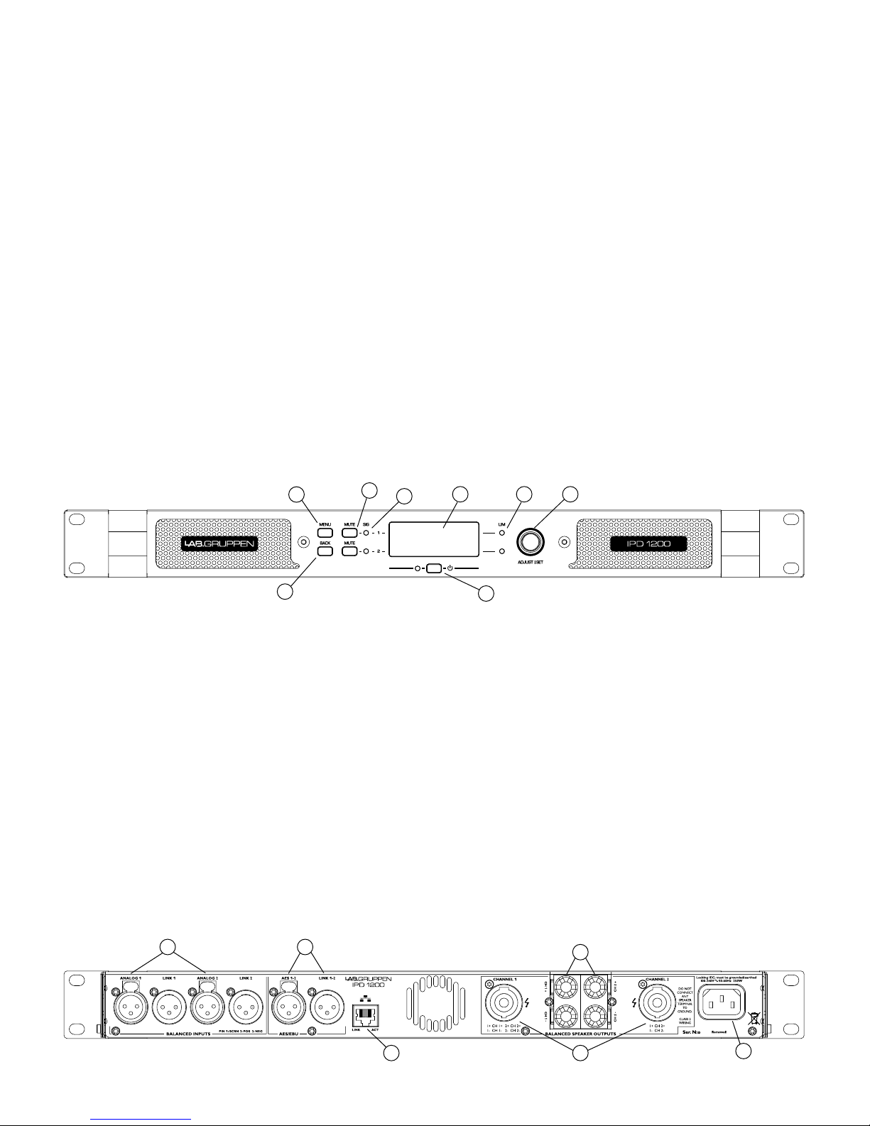
Front panel
The following indicators and controls are available on the front panel:
1 MENU – Selects MENU mode and conrms a given preset name.
2 BACK – Moves backward through menu layers in MENU mode.
3 MUTE – Mutes corresponding channel as indicated.
4 SIG – Illuminates green when signal is present. Illuminates red when
signal is clipping (pre input mixer)
5 POWER – Indicates STANDBY (red)
6 LIM (limit) – Illuminates when the amplier limits the signal.
Limiting is engaged when the channel:
• Reaches the selected voltage limit
• Rail voltage sags below the selected threshold (both LEDs ash
rapidly for 1.5 sec)
• Maximum current output reached
• Mains voltage cannot maintain full rail voltage
1
2
3
4
5
6 78
7 ADJUST/SET (Rotary Encoder) – Rotation moves through the menu
and adjusts the currently selected parameter when in setup mode.
Pressing down on the knob selects a given parameter or advances
further into the menu.
In operating mode, rotation of the ADJUST/SET encoder adjusts
output gain (outputs ganged).
8 BACKLIT DISPLAY
In operating mode, the display shows the following values and status
indicators:
• Level – Horizontal VU meters for each channel
• Device name and Preset name
In setup mode, the display shows currently selected menu locations
and parameters. For more information on DSP setup procedures,
please refer to the Operation Manual.
Rear panel
The following connectors are available on the rear panel:
1 ANALOG INPUTS and LINK - XLR-F input connectors provided for
each channel, with XLR-M link output connectors.
2 AES3 INPUT and LINK – AES3 digital inputs are on an XLR-F
connector with a link output on an XLR-M connector.
3 NETWORK (Ethernet) – An RJ45 jack is supplied for connection
to an Ethernet network for external control and monitoring, either by
a direct wired connection or via an external WiFi router to an iPad or
tablet. LEDs below the connector indicate valid network connection
(LINK) and network activity (ACT).
1 2
3 4
5
6
4 speakON OUTPUT CONNECTORS – Both channel outputs are
available on a four-pole connector at the left; either channel 1 or both
channels 1 and 2 may be connected. Only channel 2 is available on
the connector to the right.
5 BINDING POST CONNECTORS – Connectors for channel 1 and
channel 2.
6 AC LINE INPUT – A locking IEC receptacle accepts the AC line
input, 50 Hz or 60 Hz, 100 V – 240 V. Use an IEC cable with the proper
connector for country of use.
Page 5

5
Input connections
Analog Inputs
Analog inputs are available on two standard XLR-F latching connectors.
The inputs are electronically balanced. The impedance is 20 kohms, and
the inputs can accept a maximum input level of +26 dBu.
Polarity is as follows:
Pin 1 = screen (shield), pin 2 = positive (+), pin 3 = negative (-).
Analog Links
Two latching XLR-M connectors are adjacent to the analog input
connectors and are paralleled to the input connectors to provide an
unprocessed analog loop-through to feed additional IPD Series units
or other equipment.
AES3 Inputs
A latching XLR-F connector accepts an AES3 digital audio signal. Input
impedance is 110 ohms. (Ensure that 110 ohm digital audio cables are
used; standard XLR microphone cables are rarely suitable for reliable
digital audio transmission.)
AES3 is a stereo digital format, and therefore both inputs are fed via a
single connector. Selection of the analog or digital inputs is made via
the front panel display or IntelliDrive Controller software.
AES3 Link
A latching XLR-M connector is tted adjacent to the AES3 input
connector. This is an active link which sends an unprocessed
AES3 loop-thru to feed additional IPD units. The design requires no
termination load when the unit is the last connected.
Fig 1
Channel 1 sent
through to top box.
Channel 2
Channel 1 and 2
Channel 1
Output connections
Two types of power output connections are available on IPD
Series ampliers: Neutrik speakON and binding post. The
two types are connected in parallel. Loudspeakers may be
connected to both at the same time, but this is generally not
recommended as total impedance may be too low.
Binding Posts
Power outputs for loudspeaker connection are available on two fully
enclosed binding posts. Observe signal polarity as indicated.
speakON Connectors
Outputs for both channel 1 and channel 2 are available on a four-pole
speakON connector to the left. The two-pole speakON to the right
connect to output 2 only. See diagram for output connection and
polarity.
*see g 1
NOTE! When connecting wiring to Speaker Terminals, the installation
shall be made by an instructed person or ready-made leads or cords
shall be used
Bridge Mode
The IPD Series employs an inherently bridged Class D output topology;
Under no circumstances should the IPD Amplier be bridged, this may
cause undesired operating performance.
Page 6

6
DSP configuration
Default conguration
IPD Series ampliers are shipped with default DSP settings that allow
immediate use in many common applications with no need for further
DSP conguration. The default mode is suited for use with the stereo
program into full range loudspeakers. The main signal routing and
parameter settings are as follows:
Input mixer:
Analog 1 and AES1 are routed to Ch. 1
Analog 2 and AES 2 are routed to Ch. 2
AES3 to analog failover is OFF Output Mute: Muted
Mode: Stereo Output EQ: Flat
Input levels: 0 dB Delay: Off
Input EQ: Flat Crossover: Off
Output levels: 0 dB
Fig 2
Analog 1
Analog 2
AES 1
AES 2
Input 1
Levels
Input 1
EQ
Input 1
delay
Output 1
Levels
Output 1
EQ
IDEEA
Amplifier
Output 1
Delay
Clip Limiter
Clip Limiter
Rail Sense Limiter
SCVPLX-Over
Input 2
Levels
Input 2
EQ
Input 2
delay
Output 2
Levels
Output 2
EQ
IDEEA
Amplifier
PSU
Output 2
Delay
SCVPLX-Over
Input
Mixer
Fig 3
Presets
Load
Store
Meters
Mixer
I/O Meters
Input 1 & 2
Gain
Delay
Link
Imput
Mixer
Device Config
Mode
Lock
LCD
Brightness
Device
Name
Device Info
Serial
Number
Temperature
Reading
Mac
Address
IP Address
H/W Version
Software
Version
Output 1 & 2
Gain Delay
Link
Limiter
Threshold
X-Over
LPF
HPF
Phase
Norm/
Invert
Enable
Type
Freq
Gain
Q / BW
PEQ 1-10
Enable
Type
Freq
Gain
Q / BW
PEQ 1-10
Signal ow block diagram
The block diagram below shows the signal ow from inputs to outputs.
*see g 2
Front panel conguration
Input mixing and routing, as well as adjustment of all DSP parameters,
may be congured using the Menu and Back buttons and the Adjust/
Set rotary encoder. The following menu tree is keyed to points in the
signal ow block in g 2.
*see g 3
Page 7

7
IntelliDrive Controller software
and network configuration
Software and App Downloads and Installation
For download of the IntelliDrive Controller software for Mac and
PC, please visit www.ipdseries.com. Instructions for installation are
available via this link.
The IntelliDrive Controller app for iPad Is available from Apple in the
App Store.
Network configuration
A network of IPD ampliers may be congured using standard,
off-the-shelf Ethernet router and Cat-5 cabling. If the router is
WiFi enabled, the IPD amplier network will be accessible using an
iPad or laptop computer running IntelliDrive Controller software.
The IPD network employs a star topology only. Each amplier must be
connected individually to the router.
Wireless Router
Cat-5e
iPad / Tablet
iPad
PC or Mac Computer
Cat-5e
(direct connection may require
crossed cable or MDI/X capable NIC)
Network Router
Cat-5ePC / Mac
PC / Mac
Network conguration is automatic. Each amplier is identied by a
unique IP address, which is shown in the Global view and the device
header panel of IntelliDrive Controller.
For more detailed information on network conguration, please refer to
the IPD Series Operation Manual.
Input mixing/routing and DSP conguration using
IntelliDrive Controller
All input mixing /routing functions and DSP conguration parameters
are accessible and adjustable using IntelliDrive Controller software.
The six main window views are shown below. For more detailed
information on mixing/routing and DSP adjustment, please refer to the
IPD Series Operation Manual.
Page 8

8
Global
The Global view shows all devices on the network and accesses the
following functions:
• Naming devices (ampliers) and groups
• Forming groups of devices
• Creating and deleting groups
• Muting ampliers individually or in groups
• Power On/Off individually or in groups
• Monitoring of output levels
• Devices selected for a group are controlled simultaneously from any
• of the device UI:s in that group.
Device Header
The device header panel appears at the top of each conguration
window for a selected device. The header panel accesses the following
functions and information:
Return to Global
• Power on/off
• Output mute (per channel)
• Device name
• Online/Ofine indication
• IP address
• Temperature reading
• Current preset
Preset store and recall (device or computer)
Input Mixer
The Input Mixer view accesses the following functions:
• Device set-up (stereo or 2-way mode)
• Input mixing
• AES3 to analog failover on/off
Levels
The Levels view accesses the following functions:
• Input Mix Bus Levels
• Output levels
• Output limiters
• Linking of inputs and outputs.
Page 9

9
Input EQ
Input EQ view is selectable per channel. Input EQ accesses the
following functions:
• Parametric equalizer (up to 10 bands)
• High-pass lter
• Low-pass lter
• Output level and limiting status
• Input delay (up to 2 sec)
Output EQ
Output EQ view is selectable per channel. The Output EQ view
accesses the following functions:
• Parametric equalizer (up to 10 bands)
• High-pass lter
• Low-pass lter
• Output level and limiting status
• Output delay (up to 2 sec)
Crossover (X-Over)
The Crossover view accesses the following functions for each output:
• High pass lter
• High pass lter type
• High pass lter cutoff frequency
• Low pass lter
• Low pass lter type
• Low pass lter cutoff frequency
• Output level and limiter status
Page 10

10
Notes
Page 11

11
Notes
Page 12

Intellidrive™, IPD™ and Intelligent Power Drive™ are trademarks of Lab.gruppen AB. All other trademarks remain the property of their respective owners.
Copyright © 2013 Lab.gruppen AB. All rights reserved.
labgruppen.com
 Loading...