

Page 1
User's Manual Document 1374
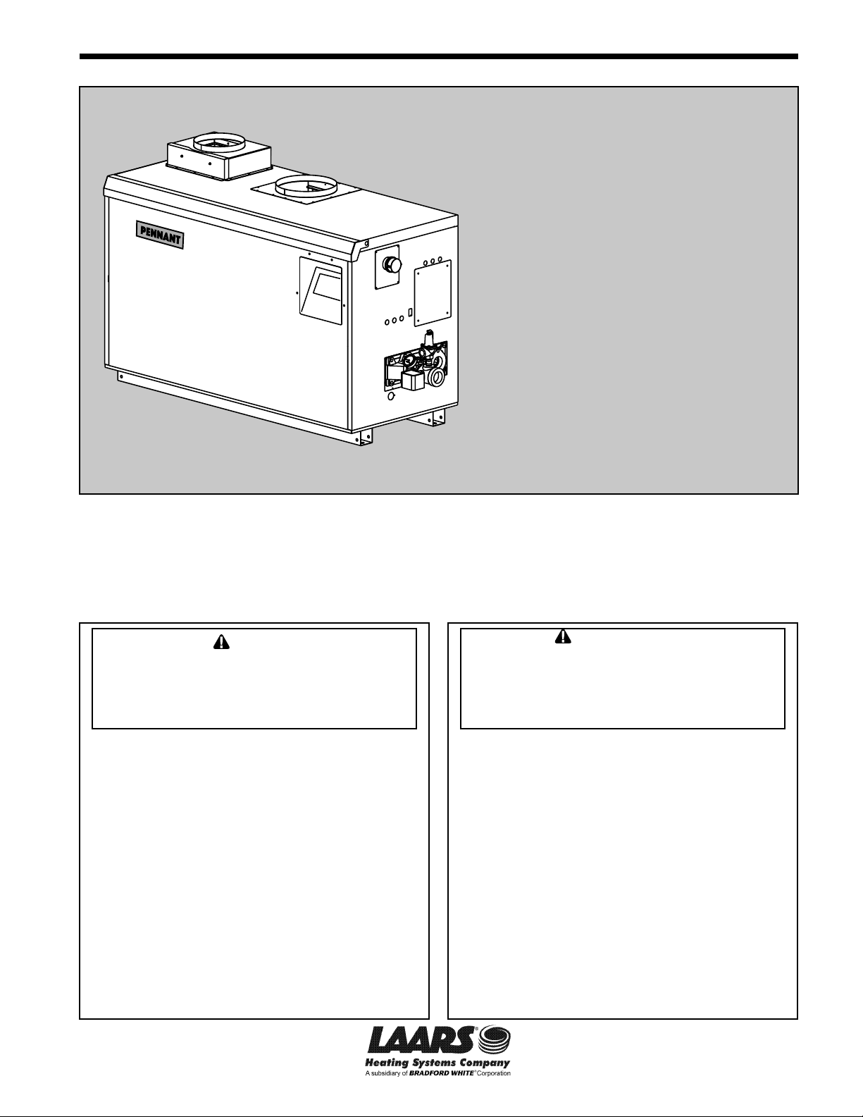
User's Manual for
™
PENNANT
includes
Hydronic Boiler
Model PNCH
Water Heater
Model PNCV
Sizes 500-2000
U.S. Reg. 2,765,423
'LOW TEMP PENNANT'
FOR YOUR SAFETY: This product must be installed and serviced by a professional service technician,
qualied in hot water boiler installation and maintenance. Improper installation and/or operation could
create carbon monoxide gas in ue gases which could cause serious injury, property damage, or death.
Improper installation and/or operation will void the warranty. For indoor installations, as an additional
measure of safety, Laars strongly recommends installation of suitable Carbon Monoxide detectors in the
vicinity of this appliance and in any adjacent occupied spaces.
WARNING
If the information in this manual is not
followed exactly, a re or explosion may
result causing property damage, personal
injury or loss of life.
Do not store or use gasoline or other
ammable vapors and liquids in the vicinity
of this or any other appliance.
WHAT TO DO IF YOU SMELL GAS
• Do not try to light any appliance.
• Do not touch any electrical switch; do not
use any phone in your building.
• Immediately call your gas supplier from a
nearby phone. Follow the gas supplier's
instructions.
• If you cannot reach your gas supplier, call
the re department.
Installation and service must be performed
by a qualied installer, service agency, or gas
supplier.
Assurez-vous de bien suivres les instructions
données dans cette notice pour réduire au
minimum le risque d’incendie ou d’explosion
ou pour éviter tout dommage matériel, toute
blessure ou la mort.
Ne pas entreposer ni utiliser d’essence ni
d’autres vapeurs ou liquides inammables dans
le voisinage de cet appareil ou de tout autre
appareil.
QUE FAIRE SI VOUS SENTEZ UNE ODEUR DE GAZ:
• Ne pas tenter d’allumer d’appareils.
• Ne touchez à aucun interrupteur. Ne pas vous
servir des téléphones dansle bâtiment où vous
vous trouvez.
• Appelez immédiatement votre fournisseur de
gaz depuis un voisin. Suivez les instructions du
fournisseur.
• Si vous ne pouvez rejoindre le fournisseur de
gaz, appelez le sservice des incendies.
L’installation et l’entretien doivent être assurés par
un installateur ou un service d’entretien qualié ou
par le fournisseur de gaz.
AVERTISSEMENT
H2380000-
Page 2

Page 2
TABLE OF CONTENTS
LAARS Heating Systems
SECTION 1 Caring For Your Pennant ....................... 3
1.A General Care ............................................3
1.B Annual Inspection of Flue and Vents ........3
1.C In the Event of a Power Failure ................3
1.D Full Service Every Three (3) Years ...........3
SECTION 2 Touchscreen and System Ops ...............4
2.A The Home Screen ....................................4
2.A.1 Home Screen Status Window...................4
2.A.2 Home Screen Active Icons .......................5
2.B Lock/Unlock Display Screen .....................6
2.C Keypad Operations ...................................7
2.D Quick Start ..............................................8
2.D.1 CH /DHW .................................................8
2.D.1.a CH1 /DHW11 ............................................ 8
2.D.1.b CH2/DHW2 2 ............................................8
2.D.2 DHW/DHW3 ............................................9
2.D.3 Outdoor Reset .........................................9
2.D.4 Warm Weather Shut Down ...................... 9
2.D.5 Anti-Short Cycle .....................................10
2.D.6 Time & Date ........................................... 10
SECTION 3 Electrical Connections ..........................11
3.A Installation Warnings ...............................11
3.B Line Voltage Connections ........................11
3.B.1 Main Power..............................................11
3.B.2 Pump Power ............................................11
3.B.3 Boiler/Heater Pump ................................11
3.B.4 Auxiliary Power Output ............................11
3.C Low Voltage Connections ....................... 12
3.C.1 Field Wiring - Inputs................................12
3.C.1.a Safety Interlocks .....................................12
3.C.1.b PNCH/PNCV Heat Demands .................12
3.C.1.c Field Inputs (Open/Closed)..................... 12
3.C.1.d Temperature Sensors ............................. 12
3.C.2 Field Wiring - Outputs ............................13
3.C.2.a Dry Contacts ...........................................13
3.C.1.e Analog (BAS) Input .................................13
3.C.2.b Cascade RS485 .....................................14
3.C.2.c BAS RS485 ............................................ 14
3.C.2.d 24VAC .................................................... 14
3.D Cascade Wiring Connections .................15
SECTION 4 Burner Set Up ......................................15
4.A Set Up for 0 to 2500 Feet Altitude ..........15
4.B Set Up for High Altitude
( >2500 Feet ) .........................................16
Page 3
Pennant (500-2000), User's Manual
SECTION 1 Caring For Your
Pennant
Your Pennant will require very little
Maintenance. However, as with any ne appliance
there are certain steps that should be taken to ensure
continuing optimum performance.
Page 3
WARNING
Do not use this boiler if any part has been
under water. Immediately call a qualied
service technician to inspect the boiler and to
replace any part of the control system and any
gas control which has been under water.
1.A General Care
Keep the area around the Pennant clean and
free from combustible materials, gasoline and other
ammable liquids and vapors.
The Pennant must be completely isolated and
protected from any source of corrosive chemical fumes
such as trichlorethylene, perchlorethylene, chlorine,
etc.
Keep grille openings on the boiler free for proper
ventilation of interior components.
Do not obstruct or block a free ow of air to the
boiler to ensure proper ventilation.
If desired, clean the jacket surfaces with a damp
cloth and mild detergent. Do not use ammable
cleaning materials.
If sidewall vented, keep the vent terminal clear
of obstructions — do not pile snow against the vent
terminal. Clean the air lter(s) often, and then develop
an appropriate maintenance schedule.
1.B Annual Inspection of Flue and Vents
Visually inspect the vent pipe once a year. Should
any deterioration exist, have the affected parts replaced
by a qualied service person.
WARNING
Should overheating occur or the gas supply
fail to shut off, do not turn off or disconnect the
electrical supply to the pump. Instead, shut
off the gas supply at a location external to the
boiler.
FOR SERVICE
Contact your installing contractor, gas utility,
Laars dealer, or call Laars for the nearest
authorized representative in your area.
1.C In the Event of a Power Failure
The Pennant can not be operated during an
electrical power outage. If there is an extended power
outage with danger from freezing, then the Pennant
(and all other water systems) should be drained
completely. When draining the boiler, turn off main
electrical disconnect switch. When placing back in
service, refer to start-up instructions in the Installation
and Operation Manual for lling and purging.
Draining and lling shall only be done by a qualied
service person.
1.D Full Service Every Three (3) Years
In addition to the annual visual inspections, a
qualied service agency should conduct a detailed
inspection of all ue product carrying areas of the
boiler and its venting system.
Page 4
Page 4
Icon
Description
Setpoint
CSP:
CH1:
CH2:
DHW:
Heat Demand
Setpoints
NOTE: The heat
demand set point
will turn green in
color when active.
Pumps
Boiler:
System:
DHW:
Pump Status
(On/Off)
Boiler Status
B1: Running
B2: Running
Stage 1:
Stage 2:
Stage 3:
Stage 4:
Blower 1:
Blower 2:
OAT:
Pennant Status:
• Burner Bank 1
• Burner Bank 2
• Staging (on/off)
• Blower Speed
(high/low)
• OAT - Outdoor
Ambient
Temperature
(when
connected)
SECTION 2 Touchscreen and System Operations
2.A The Home Screen
Figure 1. The Home Screen
LAARS Heating Systems
2.A.1 Home Screen Status Window
The central area of the home screen displays the
current status information for the unit.
Heat Demand Setpoints.
Pump Status.
Boiler Status (Boiler Bank).
System Temp.
and DHW Temp (if installed)
Heat Demand Setpoints.
NOTE: The heat demand set point will
turn green in color when active
Model Stages
Low Temp On/Off
500 - 750 2
1000 3
1250 - 2000 4
Table 1. Stages per Model
Inlet & Outlet Temperature.
Figure 2. The Status Display Area, dened.
Pump Status.
System Supply /
Return Temperature
(when connected).
DHW
Temperature
(when connected).
Page 5

Pennant (500-2000), User's Manual
2.A.2 Home Screen Active Icons
Name Icon Description
Page 5
Security
Quick Start
Congure
Service
Messages
Active
Demands
Navigation
Bar
Displays the current lock status. Touch the lock icon to lock or unlock the
Touchscreen Display.
Provides quick touch access to the most commonly used parameters for easy
installation.
Will take you to ALL of your congurations and parameters for a detailed setup of
the unit. This is the largest group of menu screens.
Allows the service technician to access the basic diagnostic and troubleshooting
information.
Will show an 'Exclamation' when there is a message.
Clicking onto the Message icon will take you to the message itself.
The USB functionality will show the USB Icon at this location, if
being used.
Will show icons that indicate the active parameters that are
currently in demand.
The Navigation Bar is the constant indicator of where you are as you
navigate into and out of the touchscreens. See Screen 2 on page 7
ERROR Codes also show in the Navigation Bar when there is one of several unit
errors or shut-downs that have occured.
Date &
Time
Table 2. The Active Icons on the Home Screen, and what they do.
For Display Only. To change date and time, go to the
Conguration menu.
Page 6

Page 6
2.B Lock / Unlock Display Screen
Password Protection:
To change parameters, a password is required.
The control system includes three levels of password
protection.
-OEM Password: Setup and parameter changes
available only to the factory.
-INSTALLER Password: Setup and parameter
changes made during the initial setup and
commissioning. The installer password is 17.
-USER Password: Non-critical adjustments and
functions. The user password is lhs.
Logout. Allows the user to log out of the
password.
Password Unlocked. The lock will change
states depending on the Password level that was
entered. The inside of the Lock Icon will also change
between O, I, or U to denote what level you are logged
into. O= OEM; I= Installer; U= User.
There are 2 ways you can navigate to the
Password Entry screen.
a. By pressing the “Lock” icon on the center of the
top bar of any screen.
b. By navigating to “Congure”, then by pressing
the “Login” button on the lower right hand corner
of the “Congure” screen.
LAARS Heating Systems
Screen 1. Sign in Screen
Password Locked. If the password
is “Locked”, the user is automatically logged out after
a certain amount of time of inactivity on the screen. If
the password is “Unlocked” then the user will not be
automatically logged off. You can set this time interval
in Service -> Screen -> Auto Lock Timeout.
This screen works just like a normal “Qwerty”
keyboard. After entering in the correct password
needed, select “Enter” to unlock the appropriate
control settings.
Page 7

Pennant (500-2000), User's Manual
2.C Keypad Operations
As you navigate in, you will nd that all screens have either
a numeric keypad to enter in your customizable parameters OR
selection buttons to choose the device of your conguration.
NOTE: You can always tell exactly where you have navigated to by
looking at the icons in the
In this example you are in
Home/Congure/Central Heat/Central Heat One
Navigation Bar.
Page 7
Shows the current setting
of the Parameter.
These windows will reect the
allowable ranges that the setting
can be adjusted to.
To delete the current setting before
entering in the new value.
“Up and Down” arrows are used to
increment the setting accordingly.
Screen 2. A typical numeric keypad entry screen.
Screen 3. A Typical selection screen.
The “Enter” button is used to accept
the new value that was just entered.
This is the indicator that will be shown when
the correct password has been entered to
allow the setting to change.
The highlighted button (orange)
shows which one is selected.
Some screens may only allow you
to set one or the other, while some
other screens (example: pump
selection) will allow you to select
any or all of the options.
The “Back” button jumps to the
previous screen.
Page 8

Page 8
2.D Quick Start
To navigate to the Quick Start Screen, touch the
Quick Start Icon in the lower left-hand portion of the
Home Screen.
Screen 4. Home Screen
LAARS Heating Systems
Touching CH1/DHW1 navigates to the CH1/
DHW1 Quick Start Screen
1
2.D.1.a CH1 /DHW1
Screen 7. CH1/DHW1 Quick Start Screen
Screen 5. Quick Start Screen
CH is Central Heat DHW is Domestic Hot Water
2.D.1 CH /DHW
On the Quick Start Screen, touch the CH/DHW
thermometer icon to navigate to the CH Selection
Screen
There are two identical heat demands, CH1/DHW1
and CH2/DHW2, each with independent control
algorithms and independent inputs on the input
terminal strip.
NOTE: CH1 applies to hydronic units (PNCH),
while DHW1 applies to volume water units (PNCV).
• Enable/Disable – This allows CH1/DHW1 to be
enabled/disabled. The default setting is Enabled.
• Set Point – This is the temperature that this heat
demand will control to.
2
2.D.1.b CH2/DHW2
To navigate to the CH2/DHW2 Quick Start Screen,
touch the CH2 Icon on the CH/DHW Quick Start
Selection Screen.
Screen 8. CH2/DHW2 Quick Start Screen
Screen 6. CH/DHW Quick Start Selection Screen
NOTE: CH2 applies to hydronic units (PNCH),
while DHW2 applies to volume water units (PNCV).
Page 9

Pennant (500-2000), User's Manual
Page 9
2.D.2 DHW/DHW3
To navigate to the DHW/DHW3 Quick Start
Screen, touch the DHW faucet icon on the Quick Start
Screen.
Screen 9. DHW/DHW3 Quick Start Screen
The DHW/DHW3 Quick Start Screen allows
adjustment of the following parameter:
• Enable/Disable – This allows DHW/DHW3 to be
enabled/disabled. The default setting is Enabled.
• Set Point – This is the temperature that this heat
demand will control to.
temperature at which the Pennant will maximize the
boiler outlet temperature to the Maximum Water
Temperature.
NOTE: Outdoor functionality is applicable to
hydronic units only, and is explained in Installation
Manual (Doc 1373)
2.D.4 Warm Weather Shut Down
To navigate to the Warm Weather Quick Start
Screen, touch the Warm Weather Icon on the Quick
Start Screen.
NOTE: A DHW/DHW3 heat demand can be
initiated by an aquastat or sensor, see Sections 5.3.1.2
and 5.3.1.4 respectively.
2.D.3 Outdoor Reset
To navigate to the Outdoor Quick Start Screen,
touch the Outdoor Icon on the Quick Start Screen.
Screen 10. Outdoor Quick Start Screen
The Outdoor Quick Start Screen allows the
adjustment of the following parameters:
• Enable/Disable – This allows Outdoor Reset to
be enabled/disabled. The default setting is Enabled.
• Maximum Ambient Temperature – The
outdoor temperature at which the Pennant will limit
the boiler outlet temperature to the Minimum Water
Temperature.
• Minimum Ambient Temperature – The outdoor
Screen 11. Warm Weather Quick Start Screen
The Warm Weather Quick Start Screen allows
adjustment of the following parameters:
• Temp Min – Upon an active warm weather
shutdown condition, this is the temperature at which
the Pennant will reset the shutdown condition to
satisfy a heat demand.
• Temp Max – This is the temperature at which the
warm weather shutdown condition will occur.
• Feature Options – This parameter provides the
ability to either disable warm weather shutdown or
upon a warm weather condition, congure the Pennant
to shut down immediately or to shut down after the
current heat demand is satised.
Page 10

Page 10
LAARS Heating Systems
2.D.5 Anti-Short Cycle
To navigate to the Anti-Short Cycle Quick Start
Screen, touch the Anti-Short Cycle Icon on the Quick
Start Screen.
Screen 12. Anti-Short Cycle Quick Start Screen
The Anti-Short Cycle Quick Start Screen allows
adjustment of the following parameter:
• Cycle Time – The amount of time after a heat
demand is satised that the Pennant will wait to satisfy
the next active heat demand.
NOTE: Anti-Short Cycle Time does not apply to
DHW/DHW3 heat demands.
2.D.6 Time & Date
To navigate to the Time & Date Quick Start
Screen, touch the Time & Date Icon on the Quick Start
Screen.
Screen 13. Time & Date Quick Start Screen
The Time & Date Quick Start Screen allows
adjustment of the following parameters:
• Hour – The hour that will be displayed in the
upper banner on each screen, and the time captured in
the date/time stamp for lock-out conditions displayed
on the history screen.
• Minute – The minute that will be displayed in the
upper banner on each screen, and the time captured in
the date/time stamp for lock-out conditions displayed
on the history screen.
• Month – The month that will be displayed in the
upper banner on each screen, and the date captured in
the date/time stamp for lock-out conditions displayed
on the history screen.
• Day – The day that will be displayed in the upper
banner on each screen, and the date captured in the
date/time stamp for lock-out conditions displayed on
the history screen.
• Year – The month that will be displayed in the
upper banner on each screen, and the date captured in
the date/time stamp for lock-out conditions displayed
on the history screen.
Page 11

Pennant (500-2000), User's Manual
Over Current Recommendations (Amps)
Pennant
Pump Only
Size
Without
Pump
With
Pump
Taco
B & G
500
15
20
15
15
750
15
20
15
15
1000 20
25 –Taco
30 – B & G
15 15
1250
25
30
15
15
1500
25
30
15
15
1750
25 – 15
20
2000
25 – 20
20
SECTION 3 Electrical Connections
3.A Installation Warnings
WARNING
This appliance must be electrically grounded
in accordance with the requirements of the authority
having jurisdiction or, in the absence of such
requirements, with the latest edition of the National
Electrical Code, ANSI/NFPA 70, in the U.S. and with
the latest edition of CSA C22.1 Canadian Electrical
Code, Part 1, in Canada. Do not rely on the gas
or water piping to ground the metal parts of the
boiler. Plastic pipe or dielectric unions may isolate
the boiler electrically. Service and maintenance
personnel, who work on or around the boiler may
be standing on wet oors could be electrocuted by
an ungrounded boiler. Electrocution can result in
severe injury or death.
Single pole switches, including those of safety
controls and protective devices, must not be wired in
a grounded line.
All electrical connections are made at the
power terminals, which are located at the rear of the
appliance, or at the input/output terminal strips which
are located on the right side of the appliance.
All internal electrical components have been
prewired. No attempt should be made to connect
electrical wires to any other location except the
terminal blocks.
Page 11
3.B.2 Pump Power
The pump circuit is identied by three 12 AWG
wires: black with a white stripe (L2), white (N2), and
green (Ground).
If desired, an installer can change the pump
mounted single service units to use a separate circuit
for the pump. Instructions to make this change are
found in the Installation Manual (Doc 1373)
Table 3. Circuit Protection
3.B Line Voltage Connections
Incoming power must be protected by the
appropriate circuit breaker (fuse) and installed by a
qualied electrician or authorized/qualied personnel.
Recommended over current protection ratings are
shown in Table 3.
3.B.1 Main Power
All non-pump mounted Pennants require a
single 120-volt supply. Pump mounted Pennant
sizes 500-1500 also use a single 120-volt supply, and
Pennant sizes 1750-2000 require two separate 120-volt
supplies.
Pennant sizes 500-1500 main power (L1, N1, and
Ground) shall be connected to the three wires supplied.
This main power circuit is identied by three solid
colored wires (10 AWG) – black (L1), white (N1), and
green (Ground).
Pennant sizes 1750-2000 main power (L1,
N1, and Ground) is identied by three solid colored
wires (10 AWG) – black (L1), white (N1), and green
(Ground). The pump circuit is identied by three 12
AWG wires.
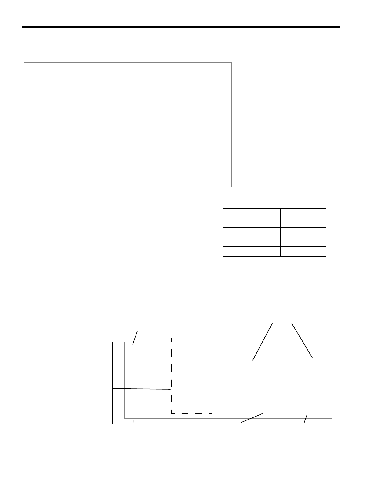
3.B.3 Boiler/Heater Pump
Conversion to a separate pump circuit requires
bringing in a separate circuit for the pump and
removing the three jumper wires within the internal
wiring of the 120-volt portion of the Pennant (see
Figure 3). This action should only be performed by
qualied personnel, with the power disconnected from
the unit.
To rewire the pump circuit, bring in a separate
120-volt circuit (L2, N2, and Ground). Remove
the jumper wires shown in Figure 3. Connect the
incoming line voltage (L2) to the main power switch
using a ¼” female insulated push on terminal. From
the other side of the main power switch, connect to
the main power terminal block, in the rear of the unit,
using a ¼” female insulated push on terminal. This
will be in the same position where the line voltage
jumper terminated. Connect N2 and Ground to the
main terminal block, in the rear of the unit, using ¼”
female insulated push terminals. These connections
will also be the same positions where the neutral and
ground jumpers were terminated.
Page 12

Page 12
terminals 7 and 8 of the input terminal strip.
DHW/DHW3: Connect the aquastat or end switch
(isolated contact only) wires to terminals 5 and 6 of the
input terminal strip. If preferred, a DHW tank sensor
can be used in lieu of an aquastat to generate a heat
demand, refer the Installation Manual (Doc 1373)
NOTE: The heat demand contacts must be dry
contacts. The Pennant controller heat demand voltage
is 24VDC.
3.C.1.c Field Inputs (Open/Closed)
Field Input 1: Field Input 1, if used, is connected
across terminals 9 and 10 of the input terminal strip.
When connected, Field Input 1 controls the Auxiliary
Dry Contact. If Field Input 1 is open, the Auxiliary
Dry Contact is open. If Field Input 1 is closed, the
Auxiliary Dry Contact is closed. Only dry contacts
can be connected to Field Input 1.
LAARS Heating Systems
Figure 3. Removing Jumpers.
3.B.4 Auxiliary Power Output
The Auxiliary Power Output, if used, is controlled
by Field Input 2. When Field Input 2 is closed,
line voltage is supplied at terminal 7 and neutral on
terminal 8 of the output terminal strip. This output is
rated for 250VAC, 2.5A maximum.
3.C Low Voltage Connections
Route all wires through the knockouts on the right side
of the Pennant. Connect low voltage wiring to the
input and output terminals shown in Figure 4. Connect
all wiring as shown on the wiring diagram.
3.C.1 Field Wiring - Inputs
3.C.1.a Safety Interlocks
Field Interlock: If the Field Interlock is utilized,
remove the jumper from the terminals 1 and 2 of the
input terminal strip and wire the interlock to these
terminals. Only dry contacts can be connected to the
Field Interlock terminals.
NOTE: Safety chain voltage is 24VDC.
3.C.1.b PNCH/PNCV Heat Demands
CH1/DHW1: Connect the thermostat/aquastat or end
switch (isolated contact only) wires to terminals 3 and
4 of the input terminal strip.
CH2/DHW2: Connect an additional thermostat/
aquastat or end switch (isolated contact only) wires to
Field Input 2: Field Input 2, if used, is connected
across terminals 11 and 12 of the input terminal strip.
When connected, Field Input 2 controls the Auxiliary
Power Output. If Field Input 2 is open, the Auxiliary
Power Output is off. If Field Input 2 is closed, the
controller turns power on at the Auxiliary Power
Output.
NOTE: The controller applies 24VDC to the Field
Inputs to detect the status of the contacts.
3.C.1.d Temperature Sensors
System Supply: The system supply sensor, if used, is
connected to terminals 14 and 15 of the input terminal
strip. When connected, the controller automatically
detects the presence of this sensor. If installed, the
Pennant controls the staging of the burners to maintain
the system supply temperature to the heat demand set
point. The system supply temperature is shown on
the home screen above the red system input arrow, see
Figure 1 on page 4. This sensor is supplied loose
with the Pennant and is installed in the piping or tank
per the suggested piping diagrams.
System Return: The system return sensor, if used, is
connected to terminals 16 and 17 of the input terminal
strip. When connected, the controller automatically
detects the presence of this sensor. There is no control
logic associated with this sensor. When connected,
this temperature is shown on the home screen above
the blue system output arrow. This sensor is supplied
loose with the Pennant and is installed in the piping or
tank per the suggested piping diagrams.
Domestic Hot Water (DHW): The DHW sensor, if
used, is connected to terminals 18 and 19 on the input
Page 13

Pennant (500-2000), User's Manual
Figure 4. Input and Output Terminal Strips
Page 13
Detail
3.C.2 Field Wiring - Outputs
3.C.2.a Dry Contacts
terminal strip. When connected, the Pennant will use
this sensor to perform the DHW thermostat function.
The controller automatically detects the presence
of this sensor and initiates a call for heat when the
DHW temperature drops below the DHW set point
by the value of the DHW On Hysteresis (DHW Set
Point – DHW On Hysteresis = DHW heat demand).
The DHW heat demand is satised when the DHW
temperature rises above the DHW set point by the
value of the DHW Off Hysteresis (DHW Set Point +
DHW Off Hysteresis = DHW heat demand satised).
When connected, this temperature is shown on the
home screen below the faucet icon. This sensor is
supplied loose with the Pennant and is installed in the
tank per the suggested piping diagrams.
Outdoor: The outdoor sensor, if used, is connected to
terminals 20 and 21 of the input terminal strip. When
connected, the controller automatically detects the
presence of this sensor. If installed, options such as
outdoor reset and warm weather shutdown can be
enabled through the display.
3.C.1.e Analog (BAS) Input
Building Automation System (BAS): The BAS input,
if used, is connected to terminals 22 and 23 of the
input terminal strip. When making the connection,
adhere to the polarity designations shown on the label
or wiring diagram. The input signal can be
0 – 10 VDC or 4 – 20 mA, and can be used to control
the ring rate or set point.. The factory default setting
is for a 0 – 10VDC signal. Congure for 4 – 20 mA
by placing a jumper on CN20 on the control board, see
Figure 5.
Run: These contacts, when used, are connected to
terminals 1 (common), 2 (normally closed), and 3
(normally open) of the output terminal strip. The
controller closes the normally open set of contacts
whenever the Pennant is running. This is typically
used by a BAS to verify the Pennant is satisfying a heat
demand. Contact ratings are 250VAC, 0.6A maximum.
Alarm: These contacts, when used, are connected
to terminals 4 (common), 5 (normally closed), and
6 (normally open) of the output terminal strip. The
controller closes the normally open set of contacts
whenever the Pennant is locked out or power is turned
off. Contact ratings are 250VAC, 0.6A maximum.
DHW Pump: When connecting a domestic hot water
(DHW) pump, use terminals 9 and 10 of the output
terminals strip. As this is a dry contact, the DHW
pump contact must be wired with either the DHW
pump supply voltage or DHW pump relay coil voltage.
DHW pump functionality is congured using the touch
screen. Contact ratings are 250VAC, 1.5A maximum.
System Pump: When connecting a system pump, use
terminals 11 and 12 of the output terminal strip. As
this is a dry contact, the system pump contact must
be wired with either the system pump supply voltage
or the system pump relay coil voltage. System pump
functionality is congured using the touch screen.
Contact ratings are 250VAC, 1.5A maximum.
AUX: These contacts, when used are connected to
terminals 13 and 14 of the output terminal strip. The
controller closes this contact when Field Input 1 is
closed; otherwise, this contact remains open. Contact
ratings are 250VAC, 1.5A maximum.
Page 14

Page 14
LAARS Heating Systems
JUMPER
4 - 20mA
ANALOG
INPUTS
NO JUMPER
0 - 10VDC
JUMPERS
4-20 mA
JUMPERS
0 - 10VDC
ANALOG OUTPUTS
Figure 5. Analog Input and Output Jumper Placement
3.C.2.b Cascade RS485
Prior to wiring Pennant units for cascade operations,
select one Pennant as the lead boiler/heater. Other
Pennants connected to the lead boiler/heater will be
referred to as lag units.
Communication between lead and lag units is
accomplished using RS485. When wiring Pennant
units for cascade operations, use terminals 22 (B), 23
(A), and 24 (GND) of the output terminal strip. Use
2-wire twisted pair, shielded w/drain, communication
cable between units. Referring to Figure 6, connect
one end of the twisted pair wires to A (terminal 23),
and the other to terminal B (terminal 22), and the
drain wire to GND (terminal 24). Connect the other
end of the cable to the next Pennant, matching the
termination wiring on the previous unit, except for
GND. Only connect the drain wire to ground on one
end of the cable to avoid ground loop issues. If more
than two Pennant units are cascaded together, daisy
chain the wiring from Pennant to Pennant, keeping the
cables as short as possible.
A system supply sensor must be installed and
connected to the lead boiler, see System Supply in
Section 5.3.1.4 – Temperature Sensors. The lead
boiler will use this system supply sensor as the
temperature control sensor for cascade operations.
CH1/DHW1 terminals are used to initiate a heat
demand at the lead boiler, refer to CH1/DHW1 in Heat
Demands of the Installation Manual (Doc 1373).
3.C.2.c BAS RS485
These terminals, when used, are for RS485 serial
communication with a BAS system using BACnet
MS/TP or Modbus protocols. Use 2-wire twisted pair,
shielded w/drain, communication cable between the
BAS and Pennant.
3.C.2.d 24VAC
There are terminals for 24VAC on the output terminal
strip. These terminals are reserved for Pennant lowtemp units or a low water cuto-off option kit.
Page 15

Pennant (500-2000), User's Manual
3.D Cascade Wiring Connections
Page 15
TB2-22
TB2-24
TB2-23
TB2-22
TB2-24
TB2-23
TB2-22
TB2-24
TB2-23
Figure 6. Cascade Wiring Connections
TB2-19
TB2-21
RS485 B
RS485
GND
TB2-20
BAS
RS485 A
TB2-19
TB2-21
RS485 B
RS485
GND
TB2-20
BAS
RS485 A
TB2-19
TB2-21
RS485 B
RS485
GND
TB2-20
BAS
RS485 A
Figure 7. Cascade BAS Wiring Connections
For the complete list of wiring diagrams and logic diagrams, please see the
Installation and Operating Manual. Document 1373
SECTION 4 Burner Set Up
4.A Set Up for 0 to 2500 Feet Altitude
The Pennant appliance utilizes a modular design
to achieve its stage-ring. The setup must be
checked before the unit is put in operation.
Problems such as failure to start, rough ignition,
strong exhaust odors, etc. can be due to improper
setup. Damage to the Pennant resulting from
improper setup is not covered by the limited
warranty.
1. Using this manual, make sure the installation
is complete and fully in compliance with the
instructions.
2. Determine that the appliance and system are
lled with water and all air has been bled from
both. Open all valves.
3. Observe all warnings on the Operating
Instructions label and turn on gas and electrical
power to appliance.
4. Switch on the appliance power switch located on
the right side of the unit.
5. The Pennant will enter the start sequence, as long
as the unit is being called for heat. The blower
and pump come on for pre-purge, then the ignitor
warm-up sequence starts and after the ignitor
warm-up is complete and all safety devices are
veried, the gas valves open. If ignition doesn’t
occur, check that there is proper gas supply. Wait
5 minutes and start the unit again. During initial
start up, air in the gas line may cause the Pennant
to "lock out" during the rst few trials for ignition.
Depending on the ignition modules installed, the
manual reset button on the ignition modules may
need to be depressed to restart the Pennant.
6. With the unit running, verify the supply gas
pressure, manifold gas pressure, and CO2
according to the Table 4
Page 16

Page 16
6. With the unit running, verify the supply gas pressure, manifold gas pressure, and CO2 according to the
table below.
Natural Gas
Propane
Typical
7” w.c. (1.7kPa)
11” w.c. (2.7kPa)
Range
5” w.c. ≤ (supply pressure ) ≤ 13” w.c.
Manifold Gas Pressure
2.5” w.c. (0.62 kPa)
CO
8%
9.2%
Supply Gas
Pressure
2
Table 4. Supply Gas Pressure
7. After placing the appliance in operation, the
Burner Safety Shutoff Device must be tested.
To test:
(a) Close gas shutof
f valve with burner operating.
(b) The ame will go out and blower will continue
to run for the post pur
ge cycle. One additional
attempt to light will follow. Ignition will not occur
as the gas is off. The ignition control will lockout,
and will have to be reset before the unit will
operate.
(c) Open gas shutof
f valve. Restart the appliance.
The ignition sequence will start again and the
burner will start. The appliance will return to its
previous mode of operation.
NOTE: Sizes 1000–2000 have two ignition controls
and two ignitors, which work independently of one
another. If the ignition control for stages 1 and 2
fails to properly light the main burners for those
stages, the second ignition control will still be
active, and will be able to energize stages 3 and
4. This, of course, will only occur if all other safety
devices conrm that the unit will run in a safe
condition.
4.B Set Up for High Altitude
( >2500 Feet )
Pennant appliances may be operated at high altitude
(7700 ft., 2347 m) with a reduction in output of approximately 10%. At altitudes of less than or more than 7700
ft. (2347 m) the appliance will perform equally as well,
but with differing reductions in output. At elevations
higher than 7700 ft. (2347 m) the reduction in output
will exceed 10% and at elevations below 7700 ft. (2347
m) it will be less than 10%. High altitude adjustment
must not be made on appliances operating at elevations
below 2500 ft. (762 m).
No orice changes are required to adjust the
Pennant appliances for high altitude. High altitude
adjustment is accomplished by adjustment of the
gas valve manifold pressure and the air shutter(s).
LAARS Heating Systems
The required instruments used to assist in these
adjust-ments are a CO
or O2 Analyzer and a U-Tube
2
Manometer or other device capable of reading a
pressure of 2.5-3.0 inches w.c. (0.62-0.75 kPa).
Start the adjustment process by checking the
in the “as installed” condition. Adjust the air
CO
2
shutter(s) so that the CO
is about 8% or the O
2
about 6.8% for appliances operating on Natural Gas.
For appliances operating on LP Gas adjust the air
shutter(s) so that the CO
is about 9.2% or the O
2
about 6.8%. Appliances with two blowers should be
adjusted so that the air shutters below each blower are
open the same amount.
Once the CO
or O2 has been set, the manifold
2
pressure may be adjusted. Remove the 1/8 NPT plug
from the lower side of the gas valve that is to be
set and install a tting, hose and manometer. Start
the appliance and observe the manifold pressure.
Manifold pressure must be adjusted to 3.0 in. w.c.
(0.75 kPa) (for high altitude only, standard operating
pressure is 2.5 in. w.c. (0.62 kPa)). It is adjusted by
removing the slotted cap on the gas valve and turning
the adjustment screw (beneath the cap) clockwise to
increase pressure and replaced after the adjustments
have been completed and the tting, hose and
manometer have been removed and the 1/8" plug has
been replaced. Repeat this process until all gas valves
have been set. Note: The pressure can be set only
when the appliance is operating and only when the
particular gas valve being adjusted is energized by a
call for heat from the staging control.
After all of the gas valve manifold pressures have
been set, the CO
or O2 must be reset. CO2 or O
2
will have changed when the manifold pressure was
adjusted. Open the air shutter(s) to reduce the CO
to the values achieved previously.
O
2
The procedure is complete when all gas valves are
adjusted to a manifold pressure of 3.0 in. w
kPa) and the CO
is adjusted to 8.0% for Natural Gas
2
appliances or 9.2% for LP appliances. When using an
analyzer, the correct O2 is 6.8% for both Natural
O
2
Gas and LP appliances.
Caution
Should any odor of gas be detected, or if the
gas burner does not appear to be functioning
in a normal manner, close main shutof f valve,
do not shut off switch, and contact your heating
contractor, gas company, or factory representative.
is
2
is
2
2
2
.c. (0.75
or
Headquarters: 20 Industrial Way, Rochester, NH, USA 03867 • 603.335.6300 • Fax 603.335.3355
www.Laars.com Printed in U.S.A. © Laars Heating Systems 1710 Document 1374
Customer Service and Product Support: 800.900.9276 • Fax 800.559.1583
9 Brigden Gate, Halton Hills, Ontario, Canada L7G 0A3 (905) 203-0600 Fax: (905) 636-0666
H2380000-
 Loading...