


Installation and Operation Instructions |
Document 1176K |
|
|
Installation and Operation
Instructions for
PENNANT™
Hydronic Boiler
Model PNCH
Water Heater
Model PNCV
Sizes 500-2000
U.S. Reg. 2,765,423
FOR YOUR SAFETY: This product must be installed and serviced by a professional service technician, qualified in hot water boiler installation and maintenance. Improper installation and/or operation could create carbon monoxide gas in flue gases which could cause serious injury, property damage, or death. Improper installation and/or operation will void the warranty. For indoor installations, as an additional measure of safety, Laars strongly recommends installation of suitable Carbon Monoxide detectors in the vicinity of this appliance and in any adjacent occupied spaces.
H2214400K
 WARNING
If the information in this manual is not followed exactly, a fire or explosion may result causing property damage, personal injury or loss of life.
Do not store or use gasoline or other flammable vapors and liquids in the vicinity of this or any other appliance.
WHAT TO DO IF YOU SMELL GAS
•Do not try to light any appliance.
•Do not touch any electrical switch; do not use any phone in your building.
•Immediately call your gas supplier from a nearby phone. Follow the gas supplier's instructions.
•If you cannot reach your gas supplier, call the fire department.
Installation and service must be performed by a qualified installer, service agency, or gas supplier.
 AVERTISSEMENT
Assurez-vous de bien suivres les instructions données dans cette notice pour réduire au minimum le risque d’incendie ou d’explosion ou pour éviter tout dommage matériel, toute blessure ou la mort.
Ne pas entreposer ni utiliser d’essence ni d’autres vapeurs ou liquides inflammables dans le voisinage de cet appareil ou de tout autre appareil.
QUE FAIRE SI VOUS SENTEZ UNE ODEUR DE GAZ:
•Ne pas tenter d’allumer d’appareils.
•Ne touchez à aucun interrupteur. Ne pas vous servir des téléphones dansle bâtiment où vous vous trouvez.
•Appelez immédiatement votre fournisseur de gaz depuis un voisin. Suivez les instructions du fournisseur.
•Si vous ne pouvez rejoindre le fournisseur de gaz, appelez le sservice des incendies.
L’installation et l’entretien doivent être assurés par un installateur ou un service d’entretien qualifié ou par le fournisseur de gaz.
Page 2 |
LAARS Heating Systems |
|
|
|
|
TABLE OF CONTENTS
SECTION 1. |
|
SECTION 3. |
|
||
General Information |
|
Gas Supply and Piping |
|
||
1.1 |
Introduction....................................................... |
4 |
3.1 |
Gas Supply and Piping................................... |
13 |
1.2 |
Model Identification.......................................... |
4 |
SECTION 4A. |
|
|
1.3 |
Warranty........................................................... |
5 |
|
||
1.4 |
Dimensions....................................................... |
5 |
Water Connections – Boiler |
|
|
1.5 |
Locating the Appliance..................................... |
5 |
4A.1 |
Heating System Piping: |
14 |
1.6 |
Locating Pump-Mounted Water Heater |
|
|
Hot Supply Connections – Boiler.................... |
|
|
4A.2 |
Cold Water Make-Up – Boiler |
14 |
||
|
with Respect to Storage Tank(s)...................... |
7 |
|||
1.7 |
Locating Pump-Mounted Boiler with |
|
4A.3 |
Water Flow Requirements – Boiler................. |
14 |
|
Respect to Return/Supply Header.................... |
7 |
4A.4 |
Freeze Protection – Boiler.............................. |
14 |
1.8Locating Appliance for Correct Horizontal Vent/
|
Ducted Air Distance From Outside Wall........... |
7 |
SECTION 4B. |
|
||
|
|
|
Water Connections – Water Heater |
|
||
SECTION 2. |
|
4B.1 |
Water System Piping – Water Heater............. |
20 |
||
Venting and Combustion Air |
|
4B.2 |
Hot Water Supply Piping – Water Heater....... |
20 |
||
2.1 |
Combustion Air................................................. |
8 |
4B.3 |
Water Flow Requirements – Water Heater..... |
20 |
|
2.1.1 |
Combustion Air From Room............................. |
8 |
4B.4 |
Combined Water Heating (potable) |
20 |
|
2.1.2 |
Intake Combustion Air |
8 |
|
and Space Heating – Water Heater............... |
||
4B.5 |
Freeze Protection – Water Heater |
21 |
||||
2.2 |
Venting |
9 |
||||
|
|
|
||||
2.2.1 |
Vent Categories................................................ |
9 |
SECTION 5. |
|
||
2.2.2 |
Category I Vent |
9 |
|
|||
Electrical Connections |
|
|||||
2.2.3 |
Common Venting Systems............................... |
9 |
5.1 |
Main Power |
24 |
|
2.2.4 |
Category III Vent |
1 |
||||
5.1.1 |
Power Circuits |
24 |
||||
2.3 |
Locating Vent & Combustion Air Terminals |
11 |
||||
5.2 |
Temperature Control |
24 |
||||
2.3.1 |
Side Wall Vent Terminal |
11 |
||||
5.2.1 |
Temperature Control Description |
24 |
||||
2.3.2 |
Side Wall Combustion Air Terminal |
11 |
||||
5.3 |
External Staging Control Wiring |
26 |
||||
2.3.3 |
Vertical Vent Terminal |
12 |
||||
5.4 |
Low Water Cut-Off ......................................... |
26 |
||||
2.3.4 |
Vertical Combustion Air Terminal.................... |
12 |
|
|
|
|
2.4 |
Common Vent Test – Boilers.......................... |
12 |
|
|
|
|
2.5 |
Vent Terminals for Outdoor Units................... |
12 |
|
|
|
|
Pennant (500-2000) |
Page 3 |
|
|
|
|
SECTION 6. |
|
|
Operating Instructions |
|
|
6.1 |
Sequence of Operation.................................. |
36 |
6.2 |
Filling the Boiler System................................. |
36 |
6.3 |
Programming the Temperature Control.......... |
37 |
6.3.1 |
System Piping................................................ |
37 |
6.3.2 |
Choosing the Mode........................................ |
37 |
6.3.3 |
Programming.................................................. |
38 |
6.3.4 |
Choosing the Mode for your Application......... |
40 |
6.4 |
Advanced Topics............................................ |
42 |
6.4.1 |
Differential...................................................... |
42 |
6.4.2 |
Staging Mode................................................. |
42 |
6.4.3 |
Boiler Minimum (BOIL MIN)........................... |
43 |
6.4.4 |
Boiler Maximum (BOIL MAX)......................... |
43 |
6.4.5 |
Boiler Target Temperature.............................. |
43 |
6.4.6 |
Pump Operation............................................. |
43 |
6.4.7 |
Setpoint Operation ........................................ |
44 |
6.4.8 |
Dedicated Domestic Hot Water...................... |
44 |
6.4.9 |
Outdoor Reset Operation............................... |
44 |
6.4.10 External Boiler Operation............................... |
46 |
|
6.4.11 Limit Controls................................................. |
46 |
|
6.4.12 Advanced Programming Mode....................... |
46 |
|
6.5 |
Operating the Burner and Set Up................... |
46 |
6.5.1 |
Set Up for 0 to 2500 Feet Altitude.................. |
46 |
6.5.2 |
High Altitude Adjustment and Set Up............. |
47 |
6.6 |
Shutting Down the Pennant............................ |
47 |
6.5 |
To Restart the Pennant................................... |
47 |
SECTION 7. |
|
Maintenance |
|
7.1 System Maintenance...................................... |
48 |
7.2Appliance Maintenance and
|
Component Description.................................. |
48 |
7.2.1 |
Burners........................................................... |
48 |
7.2.2 |
Filter............................................................... |
48 |
7.2.3 |
Gas Valves..................................................... |
48 |
7.2.4 |
Manual Reset High Limit Control.................... |
48 |
7.2.5 |
Automatic Reset High Limit Control............... |
48 |
7.2.6 |
Temperature Control....................................... |
49 |
7.2.7 |
Ignition Controls............................................. |
49 |
7.2.8 |
Ignitors............................................................ |
49 |
7.2.9 |
Ignition Sensors.............................................. |
49 |
7.2.10 Transformer.................................................... |
49 |
|
7.2.11 Blowers........................................................... |
49 |
|
7.2.12 Flow Switch.................................................... |
49 |
|
7.2.13 Heat Exchanger Coil...................................... |
49 |
|
SECTION 8. |
|
|
Trouble Shooting |
|
|
8.1 |
Resolving Lockouts........................................ |
51 |
8.2 |
Delayed Ignition – Possible Causes............... |
51 |
8.3 |
Short Cycling – Boiler..................................... |
51 |
8.4 |
Short Cycling – Water Heater......................... |
51 |
8.5 |
High Gas Consumption.................................. |
51 |
8.6 |
Troubleshooting the Temperature Control...... |
51 |
8.7 |
Troubleshooting Pennant Controls................. |
51 |
SECTION 9. |
|
|
Replacement Parts |
|
|
9.1 |
General Information........................................ |
54 |
9.2 |
Parts List........................................................ |
54 |

Page 4 |
LAARS Heating Systems |
|
|
|
|
SECTION 1.
General Information
USING THIS MANUAL – Because the Pennant Boilers and Pennant Water Heaters are identical appliances, with the exception of materials of manufacture, labels and ultimate use application, this manual provides information for the proper installation, operation and maintenance of both products. Where differences exist between the application of the appliances and their operation, the sections pertinent to only one appliance or the other will be so identified.
In the Commonwealth of Massachusetts, this appliance must be installed by a licensed plumber or gas fitter.
 WARNING
The Pennant hydronic, boiler or water heater must be installed in accordance with the procedures detailed in this manual, or the Laars Heating
Systems warranty may be voided. The installation must conform to the requirements of the local jurisdiction having authority, and, in the United States, to the latest edition of the National Fuel Gas Code, ANSI Z223.1/NFPA54. In Canada, the installation must conform to the latest edition of the Natural Gas and Propane Installation Code,
CSA B149.1 and/or local codes. Where required by the authority having jurisdiction, the installation of
Pennant appliances must conform to the Standard for Controls and Safety Devices for Automatically
Fired Boilers, ANSI/ASME CSD-1. Any modifications to the boiler, its gas controls, or wiring may void the warranty. If field conditions require modifications, consult the factory representative before initiating such modifications.
1.1Introduction
This manual provides information necessary for
the installation, operation, and maintenance of Laars
Heating Systems Pennant copper tube appliances. Read it carefully before installation.
All application and installation procedures should be reviewed completely before proceeding with the installation. Consult the Laars Heating Systems factory, or local factory representative, with any issues or questions regarding this equipment. Experience has shown that most operating issues are caused by improper installation.
The Pennant appliance is protected against over pressurization. A pressure relief valve is fitted to all appliances. It is installed on the outlet header, at the water outlet of the appliance.
IMPORTANT: The inlet gas pressure to the appliance must not exceed 13" w.c. (3.2kPa).
All installations must be made in accordance with:
1)In the U.S., the " National Fuel Gas Code"ANSI Z223.1/NFPA54, Latest Edition and all applicable local codes as required by the Authorities Having Jurisdiction (AHJ), or
2)In Canada, the "Natural Gas and Propane Installation Code", CSA B149.1, latest edition and all applicable local codes as required by the AHJ.
All electrical wiring is to be done in accordance with:
1). In the U.S., the "National Electrical Code" (NEC), ANSI/NFPA 70, latest Edition and all applicable local codes as required by the AHJ, or
2). In Canada, the “Canadian Electrical Code - Part 1”, CSA STD. C22.1 and all applicable local codes as required by the AHJ.
This appliance must be electrically grounded in accordance with the applicable codes and standards referenced above.
Model Nomenclature
1 |
2 |
3 |
|
|
4 |
|
5 |
|
6 |
|
7 |
8 |
9 |
|
|
|
10 |
|
11 |
12 |
|
13 |
|
|
14 |
15 |
|
|
16 |
|
|
|||||||||||||||||||||||||||
|
|
|
|
|
|
|
|
|
|
|
|
|
|
|
|
|
|
|
|
|
|
|
|
|
|
|
|
|
|
|
|
|
|
|
|
|
|
|
|
|
|
|
|
|
|
|
|
|
|
|
|
|
|
|
|
|
|
|
P |
|
N |
C |
|
|
|
|
|
|
|
|
|
|
|
|
|
|
|
|
|
|
|
|
A |
|
|
|
C |
|
|
|
|
|
|
|
2 |
|
|
|
|
|
|
|
|
|
|
|
|
|
|
|
|
|
|
|
|||
|
|
|
|
|
|
|
|
|
|
|
|
|
|
|
|
|
|
|
|
|
|
|
|
|
|
|
|
|
|
|
|
|
|
|
|
|
|
|
|
|
|
|
|
|
|
|
|
|
|
|
|
|
|
|
|
|
||
|
|
|
|
|
|
|
|
|
|
|
|
|
|
|
|
|
|
|
|
|
|
|
|
|
|
|
|
|
|
|
|
|
|
|
|
|
|
|
|
|
|
|
|
|
|
|||||||||||||
|
SERIES |
|
|
|
|
|
|
|
|
SIZE |
|
|
|
|
|
|
|
ALTITUDE |
LOCATION |
REVISION |
|
|
|
|
OPTIONS CODE |
|
|
PUMP OPTIONS |
|
|||||||||||||||||||||||||||||
P |
|
N |
C |
|
|
|
|
|
|
|
MBTU/h |
|
|
|
|
|
|
A - 0'-10,000' |
|
|
C |
|
|
|
|
|
|
2 |
|
|
|
|
|
|
|
X - STANDARD |
|
|
X - NO PUMP |
|||||||||||||||||||
|
|
|
|
|
|
|
|
|
|
|
|
|
|
|
|
|
|
|
|
|
|
|
|
|
|
|
|
|||||||||||||||||||||||||||||||
|
|
|
|
|
|
|
|
|
|
|
0 |
5 |
0 |
0 |
|
|
|
|
|
|
|
|
|
|
|
|
INDOOR & |
|
|
SECOND |
|
|
|
|
J - CSD-1, FM, |
|
|
H - PUMP-MTD, TACO |
||||||||||||||||||||
|
|
|
|
|
|
|
|
|
|
|
|
|
|
|
|
|
|
|
|
|
|
|
|
|
||||||||||||||||||||||||||||||||||
|
|
|
|
|
|
|
|
|
|
|
0 |
7 |
5 |
0 |
|
|
|
|
|
|
|
|
|
|
|
|
OUTDOOR |
|
|
|
REV |
|
|
|
|
|
|
GAP, IL |
|
|
|
HARD WATER |
||||||||||||||||
|
|
|
|
|
|
|
|
|
|
|
1 |
0 |
0 |
0 |
|
|
|
|
|
|
|
|
|
|
|
|
|
|
|
|
|
|
|
|
|
|
|
|
|
|
|
|
|
|
|
|
|
|
|
|
|
|
|
PUMP (PNCV) |
||||
|
|
|
|
USAGE |
|
|
|
|
1 |
2 |
5 |
0 |
|
|
|
|
FUEL |
|
|
|
|
|
|
|
|
FIRING MODE |
|
|
|
|
|
|
|
HEAT EXCHANGER |
|
N - PUMP-MTD, TACO |
||||||||||||||||||||||
|
H - HYDRONIC |
|
|
|
|
|
|
N - NATURAL |
|
|
|
|
|
K - 2-STAGE (500 & 750) |
|
B - |
GLASS-LINED CAST |
|
||||||||||||||||||||||||||||||||||||||||
|
|
|
|
|
1 |
5 |
0 |
0 |
|
|
|
|
|
|
|
|
|
|
NORM WATER |
|||||||||||||||||||||||||||||||||||||||
|
V - VOLUME WATER |
|
|
|
P - PROPANE |
|
|
|
|
|
N - 3-STAGE (1000) |
|
|
|
|
|
|
|
IRON/COPPER/BRZ |
|
|
PUMP (PNCV, PNCH) |
||||||||||||||||||||||||||||||||||||
|
|
1 |
7 |
5 |
0 |
|
|
|
|
|
|
|
|
|
|
|
|
|
|
TRIM (std. on PNCV) |
|
|
||||||||||||||||||||||||||||||||||||
|
|
|
|
|
|
|
|
|
|
|
|
|
|
|
|
|
|
|
|
|
|
|
|
L - 4-STAGE (1250,1500, |
|
C - |
|
S - PUMP-MTD, TACO |
||||||||||||||||||||||||||||||
|
|
|
|
|
|
|
|
|
|
|
|
|
|
|
|
|
|
|
|
|
|
|
|
|
|
|||||||||||||||||||||||||||||||||
|
|
|
|
|
|
|
|
|
|
|
2 |
0 |
0 |
0 |
|
|
|
|
|
|
|
|
|
|
|
|
|
|
GLASS-LINED CAST |
|
||||||||||||||||||||||||||||
|
|
|
|
|
|
|
|
|
|
|
|
|
|
|
|
|
|
|
|
|
|
|
|
|
|
1750 & 2000) |
|
|
|
|
|
|
|
SOFT WATER |
||||||||||||||||||||||||
|
|
|
|
|
|
|
|
|
|
|
|
|
|
|
|
|
|
|
|
|
|
|
|
|
|
|
|
|
|
|
|
|
|
|
|
|
|
|
|
|
|
|
|
IRON/COPPER |
|
|
PUMP (PNCV) |
|||||||||||
|
|
|
|
|
|
|
|
|
|
|
|
|
|
|
|
|
|
|
|
|
|
|
|
|
|
|
|
|
|
|
|
|
|
|
|
|
|
|
|
|
|
|
|
|
|
|||||||||||||
|
|
|
|
|
|
|
|
|
|
|
|
|
|
|
|
|
|
|
|
|
|
|
|
|
|
|
|
|
|
|
|
|
|
|
|
|
|
|
|
|
|
|
|
(std. on PNCH, |
|
|
||||||||||||
|
|
|
|
|
|
|
|
|
|
|
|
|
|
|
|
|
|
|
|
|
|
|
|
|
|
|
|
|
|
|
|
|
|
|
|
|
|
|
|
|
|
|
|
|
C - PUMP-MTD, B&G |
|||||||||||||
|
|
|
|
|
|
|
|
|
|
|
|
|
|
|
|
|
|
|
|
|
|
|
|
|
|
|
|
|
|
|
|
|
|
|
|
|
|
|
|
|
|
|
|
not avail. on PNCV) |
|
|||||||||||||
|
|
|
|
|
|
|
|
|
|
|
|
|
|
|
|
|
|
|
|
|
|
|
|
|
|
|
|
|
HLW STAMP (PNCV only) |
|
|
N - |
GLASS-LINED CAST |
|
|
HARD WATER |
||||||||||||||||||||||
|
|
|
|
|
|
|
|
|
|
|
|
|
|
|
|
|
|
|
|
|
|
|
|
|
|
|
|
2 - |
GLASS-LINED CAST |
|
|
|
IRON/CU-NICKEL |
|
|
PUMP (PNCV) |
||||||||||||||||||||||
|
|
|
|
|
|
|
|
|
|
|
|
|
|
|
|
|
|
|
|
|
|
|
|
|
|
|
|
|
|
|
IRON / COPPER / BRZ |
|
|
|
(not avail. on PNCV) |
|
B - PUMP-MTD, B&G |
|||||||||||||||||||||
|
|
|
|
|
|
|
|
|
|
|
|
|
|
|
|
|
|
|
|
|
|
|
|
|
|
|
|
|
|
|
|
|
|
|
|
|||||||||||||||||||||||
|
|
|
|
|
|
|
|
|
|
|
|
|
|
|
|
|
|
|
|
|
|
|
|
|
|
|
|
|
|
|
TRIM |
|
|
|
|
|
P - |
GLASS-LINED CAST |
|
|
NORM WATER |
|||||||||||||||||
|
|
|
|
|
|
|
|
|
|
|
|
|
|
|
|
|
|
|
|
|
|
|
|
|
|
|
|
5 - |
GLASS-LINED CAST |
|
|
|
IRON / CU-NICKEL |
|
|
PUMP (PNCV, PNCH) |
||||||||||||||||||||||
|
|
|
|
|
|
|
|
|
|
|
|
|
|
|
|
|
|
|
|
|
|
|
|
|
|
|
|
|
|
|
IRON / CU-NICKEL, |
|
|
|
BRZ TRIM |
|
D - PUMP-MTD, B&G |
|||||||||||||||||||||
|
|
|
|
|
|
|
|
|
|
|
|
|
|
|
|
|
|
|
|
|
|
|
|
|
|
|
|
|
|
|
BRZ TRIM |
|
|
|
|
|
|
|
|
|
|
|
|
|
|
|
|
|
||||||||||
|
|
|
|
|
|
|
|
|
|
|
|
|
|
|
|
|
|
|
|
|
|
|
|
|
|
|
|
|
|
|
|
|
|
|
|
|
|
|
|
|
|
|
|
|
|
|
|
|
SOFT WATER |
|||||||||
|
|
|
|
|
|
|
|
|
|
|
|
|
|
|
|
|
|
|
|
|
|
|
|
|
|
|
|
|
|
|
|
|
|
|
|
|
|
|
|
|
|
|
|
|
|
|
|
|
|
|
|
|
|
|
PUMP (PNCV) |
|||
Pennant (500-2000) |
Page 5 |
|
|
|
|
1.2Model Identification
Consult the rating plate on the unit. The
following information describes the model number structure.
Model Character Designation
1-3 Model Series Designation
P N C = Pennant
4Usage
H = Hydronic
V = Volume Water
5-8 Size
05 0 0 = 500,000 BTU/h input
07 5 0 = 750,000 BTU/h input
10 0 0 = 999,000 BTU/h input
12 5 0 = 1,250,000 BTU/h input
15 0 0 = 1,500,000 BTU/h input
17 5 0 = 1,750,000 BTU/h input
2 0 0 0 = 1,999,000 BTU/h input
9Fuel
N = Natural Gas P = Propane
10Altitude
A = 0-10,000 feet
11Location
C = Indoor and Outdoor
12Firing Mode
K = Two-stage (models 500 & 750) N = Three-stage (model 1000)
L = Four-stage (models 1250 - 2000)
13Revision
2 = Second version
14Heat Exchanger
B = Glass-lined CI / copper / brz trim (std. PNCV) C = Glass-lined cast iron / copper (standard PNCH) N = Glass-lined cast iron / cu-nickel
P = Glass-lined cast iron / cu-nickel / brz trim
15Option Code
X = Standard unit
J = CSD-1, FM, IRI, IL
16Pump Options
X = No Pump
H = Pump mounted, TACO, hard water pump
N = Pump mounted, TACO, normal pump
S = Pump mounted, TACO, soft water pump C = Pump mounted, B&G, hard water pump
B = Pump mounted, B&G, normal pump
D = Pump mounted, B&G, soft water pump
1.3Warranty
Laars Heating Systems’ appliances are covered
by a limited warranty. Owners should submit online warranty registration at www.Laars.com.
All warranty claims must be made to an authorized Laars Heating Systems representative, directly to Customer Service, or online at www.Laars.com.
Claims must include the serial number and model number (this information can be found on the rating plate), installation date, and name of the installer.
Shipping costs are not included in the warranty coverage.
Some accessory items are shipped in separate packages. Verify receipt of all packages listed on the packing slip. Inspect everything for damage immediately upon delivery, and advise the carrier of any shortages or damage. Any such claims should be filed with the carrier. The carrier, not the shipper, is responsible for shortages and damage to the shipment whether visible or concealed.
1.4Dimensions
See Figure 1.
1.5Locating the Appliance
The appliance should be located to provide
clearances on all sides for maintenance and inspection.
It should not be located in an area where leakage of any connections will result in damage to the area adjacent to the appliance or to lower floors of the structure.
When such a location is not available, it is recommended that a suitable drain pan, adequately drained, be installed under the appliance.
The appliance is design certified by CSAInternational for installation on combustible flooring; in basements; in closets, utility rooms or alcoves.
Pennant Boilers or Water Heaters must never be installed on carpeting. The location for the appliance should be chosen with regard to the vent pipe lengths and external plumbing. The unit shall be installed such that the gas ignition system components are protected from water (dripping, spraying, rain, etc.) during operation and service (circulator replacement, control replacement, etc.). When vented vertically, the Pennant must be located as close as practical to a chimney or outside wall. If the vent terminal and/or combustion air terminal terminate through a wall, and there is potential for snow accumulation in the local area, both terminals should be installed at an appropriate level above grade.
The dimensions and requirements that are shown in Table 1 should be met when choosing the locations for the appliance.

Page 6 |
LAARS Heating Systems |
|
|
|
|
Ø Ø
|
|
|
|
|
|
|
|
|
Air |
Vent |
Horiz. |
Size |
A |
B |
C |
D |
E |
F |
G |
H |
Conn. |
Conn. |
Vent |
|
|
|
|
|
|
|
|
|
W* |
V* |
Pipe |
500 |
33½ |
85 |
15¾ |
40 |
5¾ |
15 |
29¾ |
76 |
33¾ |
86 |
7¾ |
20 |
8¾ |
22 |
46 |
117 |
6 |
|
15 |
8 |
20 |
6 |
15 |
||
750 |
45½ |
116 |
21¾ |
55 |
5¾ |
15 |
29¾ |
76 |
33¾ |
86 |
7¾ |
20 |
8¾ |
22 |
58 |
147 |
8 |
|
20 |
10 |
25 |
8 |
20 |
||
1000 |
57½ |
146 |
28¾ |
73 |
5¾ |
15 |
29¾ |
76 |
33¾ |
86 |
7¾ |
20 |
7 |
18 |
70 |
178 |
8 |
|
20 |
10 |
25 |
8 |
20 |
||
1250 |
68 |
172 |
34 |
86 |
1 |
8 |
26 |
30¾ |
78 |
1 |
8 |
79 |
8¾ |
22 |
8¾ |
22 |
80 |
203 |
12 |
|
30 |
12 |
30 |
10 |
25 |
10 ∕ |
|
31 ∕ |
|
|
|||||||||||||||||||||
1500 |
78½ |
199 |
39¾ |
101 |
1 |
8 |
26 |
30¾ |
78 |
1 |
8 |
79 |
8¾ |
22 |
8¾ |
22 |
91 |
231 |
12 |
|
30 |
12 |
30 |
10 |
25 |
10 ∕ |
|
31 ∕ |
|
|
|||||||||||||||||||||
1750 |
89 |
226 |
44½ |
113 |
1 |
8 |
26 |
30¾ |
78 |
1 |
8 |
79 |
8¾ |
22 |
8¾ |
22 |
101 |
256 |
12 |
|
30 |
14 |
36 |
12 |
30 |
10 ∕ |
|
31 ∕ |
|
|
|||||||||||||||||||||
2000 |
99½ |
253 |
49¾ |
126 |
1 |
8 |
26 |
30¾ |
78 |
1 |
8 |
79 |
8¾ |
22 |
8¾ |
22 |
112 |
284 |
12 |
|
30 |
14 |
36 |
12 |
30 |
10 ∕ |
|
31 ∕ |
|
|
|||||||||||||||||||||
*Air and vent connections may be on top or back of the Pennant, and are field convertible. |
|
|
|
|
Dimensions in inches cm |
||||||||||||||||||||
Figure 1. Dimensional Data.

Pennant (500-2000) |
Page 7 |
|
|
|
|
1.6 Locating Pump-Mounted Water Heater
with Respect to Storage Tank(s)
For best results, a pump-mounted Pennant water heater should be located within 15 feet (4.6m) of the storage tank(s). The pump is sized for 30 feet (9.1m) of piping.
If the appliance must be installed with longer piping runs, then larger diameter pipe or tubing shall be used. Consult the factory for assistance.
1.7 Locating Pump-Mounted Boiler with
Respect to Return/Supply Header
For the best results, a pump-mounted Pennant Boiler should be located within 15 feet (4.6m) of the supply and return headers. The pump is sized for 30 feet (9.1m) of piping.
If the appliance must be installed with longer piping runs, then larger diameter tubing shall be used. Consult the factory for assistance.
|
REQUIRED |
RECOMMENDED |
||
APPLIANCE |
CLEARANCE FROM |
SERVICE ACCESS |
||
SURFACE |
COMBUSTIBLE MATERIAL |
CLEARANCE |
||
|
inches |
cm |
inches |
cm |
Left Side |
1 |
2.5 |
24 |
61 |
Right Side |
1 |
2.5 |
24 |
61 |
Top |
1 |
2.5 |
12 |
30 |
Back |
1 |
2.5 |
**12** |
30** |
Front |
1 |
2.5 |
36 |
91 |
Vertical |
6* |
|
|
|
(Category 1) |
15.2* |
|
|
|
Vent |
|
|
|
|
Horizontal |
per UL1738 venting |
|
|
|
(Category 3) |
system supplier’s |
|
|
|
Vent |
instructions |
|
|
|
*1" (2.5cm) when b-vent is used.
**When vent and/or combustion air connects to the back, recommended clearance is 36" (91cm).
Table 1. Clearances.
1.8Locating Appliance for Correct Horizontal Vent/Ducted Air Distance
From Outside Wall
The forced draft combustion air blower/blowers in the appliance has/have sufficient power to pull air and vent properly when the following guidelines for horizontal air and vent are followed (see Table 2).
NOTE: On all model sizes, the vent collar size is larger than the size of the vent pipe that can be used. Vent collar size and horizontal pipe diameters can be found in Table 2. The larger vent collar size is to accommodate Category I (vertical) vent systems.
NOTE: When located on the same wall, the Pennant combustion air intake terminal must be installed
a minimum of 12" (30cm) below the exhaust vent terminal and separated by a minimum of 36 inches
(91cm) horizontally.
The air intake terminal must be installed high enough to avoid blockage from snow, leaves and other debris.
|
|
|
HORIZONTAL |
INTAKE AIR |
|
|
|
|
|
||
|
VENT COLLAR |
VENT PIPE |
PIPE |
MAX. PIPE |
MAX. NO. |
SIDE WALL |
SIDE WALL |
||||
SIZE |
|
SIZE |
DIAMETER |
DIAMETER |
LENGTH |
OF ELBOWS |
VENT |
COMBUSTION |
|||
|
|
|
|
|
|
|
|
|
|
TERMINAL |
AIR TERMINAL |
500 |
in. |
cm |
in. |
cm |
in. |
cm |
ft. |
m |
3 |
PART NUMBER |
PART NUMBER |
8 |
20 |
6 |
15 |
6 |
15 |
50 |
15 |
CA001401 |
CA20260701 |
||
750 |
10 |
25 |
8 |
20 |
8 |
20 |
50 |
15 |
3 |
CA001402 |
CA20260703 |
1000 |
10 |
25 |
8 |
20 |
8 |
20 |
50 |
15 |
3 |
CA001402 |
CA20260703 |
1250 |
12 |
30 |
10 |
25 |
10 |
25 |
50 |
15 |
3 |
CA001405 |
CA20260705 |
1500 |
12 |
30 |
10 |
25 |
10 |
25 |
50 |
15 |
3 |
CA001405 |
CA20260705 |
1750 |
14 |
36 |
12 |
30 |
12 |
30 |
50 |
15 |
3 |
CA001404 |
CA20260706 |
2000 |
14 |
36 |
12 |
30 |
12 |
30 |
50 |
15 |
3 |
CA001404 |
CA20260706 |
Table 2. Horizontal Vent / Combustion Air Parameters.
Page 8 |
LAARS Heating Systems |
|
|
|
|
SECTION 2.
Venting and Combustion Air
2.1Combustion Air
Pennant boilers and water heaters must have
provisions for combustion and ventilation air in accordance with Section 5.3, Air for Combustion and Ventilation, of the National Fuel Gas Code, ANSI Z223.1, or Sections 7.2, 7.3 or 7.4 of CSA B149.1,
Installation Codes, or applicable provisions of the local building codes.
A Pennant appliance may receive combustion air from the space in which it is installed, or it can be ducted directly to the unit from the outside. Ventilation air must be provided in either case.
2.1.1 Combustion Air From Room
In the United States, the most common requirements specify that the space shall communicate with the outdoors in accordance with method 1 or 2, which follow. Where ducts are used, they shall be of the same cross-sectional area as the free area of the openings to which they connect.
Method 1: Two permanent openings, one commencing within 12 inches (30 cm) of the top and one commencing within 12 inches (30 cm) of the bottom, of the enclosure shall be provided. The openings shall communicate directly, or by ducts, with the outdoors or spaces that freely communicate with the outdoors. When directly communicating with the outdoors, or when communicating to the outdoors through vertical ducts, each opening shall have a minimum free area of 1 square inch per 4000 Btu/hr (5.5 square cm/kW) of total input rating of all equipment in the enclosure. When communicating to the outdoors through horizontal ducts, each opening shall have a minimum free area of not less than
1 square inch per 2000 Btu/hr (11 square cm/kW) of
total input rating of all equipment in the enclosure. Table 3 shows data for this sizing method, for each
Pennant model.
Method 2: One permanent opening, commencing within 12 inches (30 cm) of the top of the enclosure, shall be permitted. The opening shall directly communicate with the outdoors or shall communicate through a vertical or horizontal duct to the outdoors
or spaces that directly communicate with the outdoors and shall have a minimum free area of 1 square inch per 3000 Btu/hr (7 square cm/kW) of the total input rating of all equipment located in the enclosure. This opening must not be less than the sum of the areas of all vent connectors in the confined space.
Other methods of introducing combustion and ventilation air are acceptable, providing they conform to the requirements in the applicable codes listed above.
In Canada, consult local building and safety codes or, in absence of such requirements, follow CSA
B149.1.
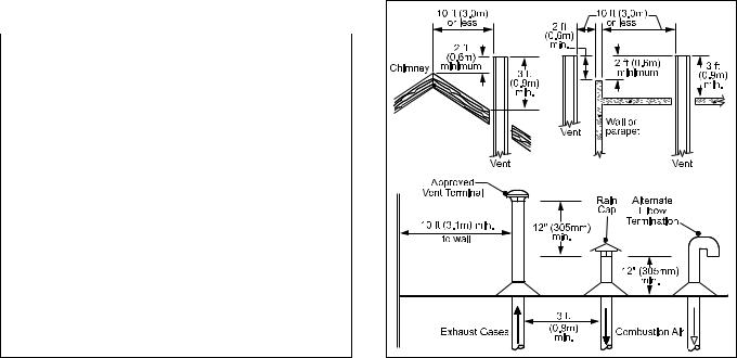
2.1.2 Intake Combustion Air
The combustion air can be taken through the wall, or through the roof. When taken from the wall, it must be taken from out-of-doors by means of the Laars horizontal wall terminal (see Table 2). When taken from the roof, a field-supplied rain cap or an elbow arrangement must be used to prevent entry of rain water (see Figure 2).
Use single-wall galvanized pipe, per Table 4, for the combustion air intake (see Table 2 for appropriate size). Route the intake to the heater as directly as possible. Seal all joints with tape. Provide adequate hangers. The unit must not support the weight of the combustion air intake pipe. Maximum linear pipe
|
EACH OPENING* |
|
SIZE |
SQUARE INCHES |
SQUARE CM |
500 |
125 |
807 |
750 |
188 |
1213 |
1000 |
250 |
1613 |
1250 |
313 |
2020 |
1500 |
375 |
2420 |
1750 |
438 |
2826 |
2000 |
500 |
3226 |
*Net Free Area in Square Inches / Square cm
Area indicated is for one of two openings; one at floor level and one at the ceiling, so the total net free area could be double the figures indicated.
This chart is for use when communicating directly with the outdoors. For special conditions and alternate methods, refer to the latest edition of ANSI Z223.1.
Note: Check with louver manufacturers for net free area of louvers. Correct for screen resistance to the net free area if a screen is installed. Check all local codes applicable to combustion air.
Table 3. Combustion Air Openings.
Figure 2. Combustion Air and Vent Through Roof.

Pennant (500-2000) |
Page 9 |
|
|
|
|
length allowed is 50 feet (15.2m). Three elbows have been calculated into the 50-foot (15.2m) linear run. Subtract 10 allowable linear feet (3.0m) for every additional elbow used (see Table 2). When fewer than 3 elbows are used, the maximum linear pipe length allowed is still 50 feet (15.2m).
The connection for the intake air pipe is on the filter box. The Pennant appliances may have venting and combustion air ducting attached to the top or the back. They are shipped with the connections at the top. For attaching either or both pipes to the back, the mounting flanges are reversible by removing the mounting screws and orienting the flanges in the desired position. Replace the screws after positioning flanges. Run a bead of silicone around the collar and slide the pipe over the collar. Secure with sheet metal screws.
In addition to air needed for combustion, air shall also be supplied for ventilation, including all air required for comfort and proper working conditions for personnel. The Pennant loses less than 1 percent of its input rating to the room, but other heat sources may be present.
2.2 Venting
2.2.1 Vent Categories
Depending upon desired Pennant venting, it may be considered a Category I or a Category III appliance.
In general, a vertical vent system will be a Category
I system. However, in rare instances, a Pennant’s vertical vent system may be considered Category
III. In the U.S., the National Fuel Gas Code (ANSI Z223.1-Latest Edition), or in Canada the CSA B149.1 (latest edition), defines a Category I vent system, and includes rules and tables to size these vent systems. If the Pennant’s vertical vent system does not satisfy the criteria for Category I venting, it must be vented as a
Category III system.
All Pennant vent systems which discharge horizontally (without the use of a power venter) are considered Category III vent systems.
2.2.2 Category I Vent
When vented as a category I appliance, the vent system must conform to the National Fuel Gas Code (ANSI Z223.1-Latest Edition) in the U.S., or in Canada, to CSA B149.1 (latest edition). The vent system must be sized and installed for a Category I
Fan-Assisted Appliance.
If chimney height is greater than 25 feet, or
TERM |
|
DESCRIPTION |
|
||
Pipe |
|
Single-wall galvanized steel pipe, 24 gauge |
|
|
minimum (either insulated or non-insulated) |
Joint |
|
Permanent duct tape or aluminum tape |
Sealing |
|
|
Table 4. Required Combustion Air Piping Material.
if multiple units are vented into the same vertical vent, a barometric damper must be installed on each appliance, such that the flue draft does not exceed (negative) 0.1" w.c.
If using a power venter for any type of Category I venting, the draft should be set between (negative)
0.01 and 0.10" w.c.
2.2.3 Common Venting Systems
Pennant units are Category I fan-assisted when vented vertically and adhering to all applicable codes. Pennant units are not allowed to be vented into a common horizontal Cat III vent system
(horizontal discharge or other configuration for Cat
III), unless a properly sized vent fan is used, and the common vent system is properly designed by the vent fan manufacturer or a qualified engineer. When common venting Pennant fan-assisted unit with other appliances through one shared vertical duct called a
“common vent”, special care must be taken by the installer to ensure safe operation. In the event that the common vent is blocked, it is possible, especially for fan-assisted devices, to vent backwards through non-operating appliances sharing the vent, allowing combustion products to infiltrate occupied spaces.
If the appliances are allowed to operate in this condition, serious injury or death may occur.
 WARNING
Operation of appliances with a blocked common vent may lead to serious injury or death. Safety devices must be implemented to prevent blocked common vent operation. If safe operation of all appliances connected to a common vent cannot be assured, including prevention of spillage of flue gasses into living spaces, common venting should not be applied, and appliances should each be vented separately.
It is for this reason that, in addition to following proper vent sizing, construction and safety requirements from the National Fuel Gas Code, ANSI Z223.1 or in Canada, from CSA B149.1 as well as all applicable local codes, it is required that installers provide some means to prevent operation with a blocked common vent. It is suggested that a blocked
vent safety system be employed such that if the switch from one appliance trips due to excessive stack spill or backpressure indicating a blocked vent condition, that all appliances attached to the vent be locked out and prevented from operating. Note that the Pennant is equipped with a blocked vent safety (pressure) switch, as shipped. However, this safety switch has only been designed and tested to be effective in installations where the Pennant is vented separately and NOT common vented with other appliances. As an additional precaution, it is recommended that a Carbon
Page 10 |
LAARS Heating Systems |
|
|
|
|
|
|
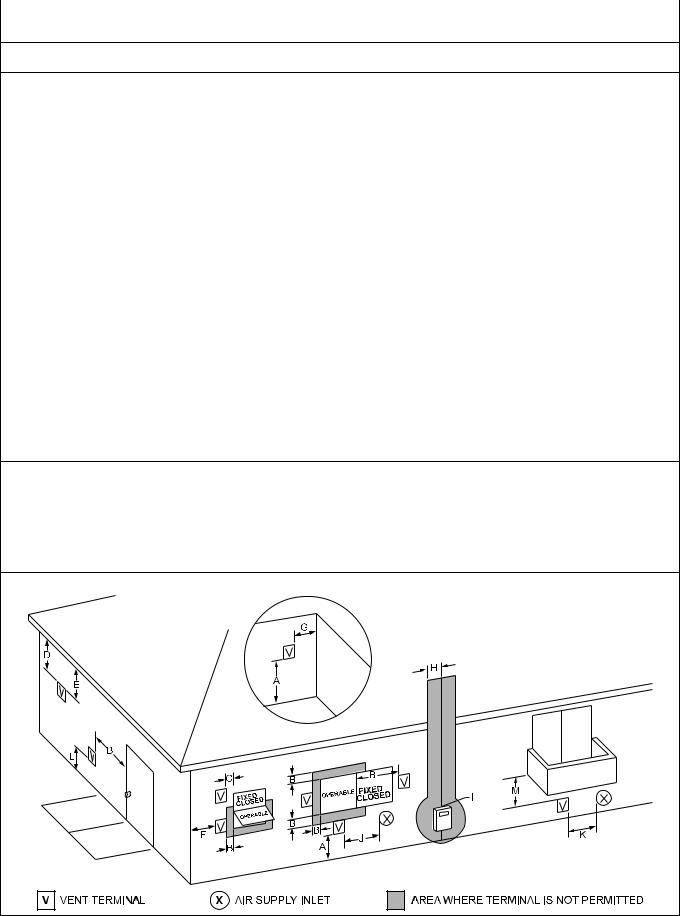
U.S. Installations (see note 1) |
Canadian Installations (see note 2) |
A = Clearance above grade, veranda, porch, 12 inches (30 cm) |
12 inches (30 cm) |
deck, or balcony |
|
B = Clearance to window or door that may be opened
4 feet (1.2 m) below or to side of opening; |
36 inches (91 cm) |
1 foot (30 cm) above opening |
|
C = |
Clearance to permanently closed window |
See note 4 |
See note 5 |
D = |
Vertical clearance to ventilated soffit located |
|
|
|
above the terminal within a horizontal |
See note 4 |
See note 5 |
|
distance of 2 feet (61cm) from the center |
|
|
|
line of the terminal |
|
|
E = |
Clearance to unventilated soffit |
See note 4 |
See note 5 |
F = |
Clearance to outside corner |
See note 4 |
See note 5 |
G = |
Clearance to inside corner |
See note 4 |
See note 5 |
H = |
Clearance to each side of center line |
|
3 feet (91 cm) within a height 15 feet above |
|
extended above meter/regulator assembly |
See note 4 |
the meter/regulator assembly |
I = |
Clearance to service regulator vent outlet |
See note 4 |
3 feet (91 cm) |
J = |
Clearance to nonmechanical air supply inlet |
|
|
|
to building or the combustion air inlet to |
4 feet (1.2 m) below or to side of opening; |
36 inches (91 cm) |
|
any other appliance |
1 foot (30 cm) above opening |
|
K = |
Clearance to a mechanical air supply inlet |
3 feet (91 cm) above if within 10 feet (3 m) |
6 feet (1.83 m) |
|
|
horizontally |
|
|
|
|
Vent termination not allowed in this location |
L = |
|
Vent termination not allowed in this location |
for category IV appliances. A vent shall not |
Clearance above paved sidewalk or paved |
for category IV appliances. For Category III |
terminate directly above a sidewalk or paved |
|
|
driveway located on public property |
appliances, vent must terminate at least 7 |
driveway that is located between two single |
|
|
feet (2.13m) above the sidewalk or driveway. |
family dwellings and serves both dwellings. |
|
|
|
For Category III appliances that do not violate |
|
|
|
the previous condition, vent must terminate |
|
|
|
at least 7 feet (2.13m) above the sidewalk or |
|
|
|
driveway. |
M = Clearance under veranda, porch, deck, |
See note 4 |
12 inches (30 cm) (see note 3) |
|
|
or balcony |
|
|
Notes:
1.In accordance with the current ANSI Z223.1 / NFPA 54 National Fuel Gas Code.
2.In accordance with the current CSA-B149.1 Installation Codes.
3.Permitted only if veranda, porch, deck, or balcony is fully open on a minimum of two sides beneath the floor.
4.For clearances not specified in ANSI Z223.1 / NFPA 54, clearance is in accordance with local installation codes and the requirements of the gas supplier.
5.For clearances not specified in CSA-B149.1, clearance is in accordance with local installation codes and the requirements of the gas supplier.
Figure 3. Combustion Air and Vent Through Side Wall.
Pennant (500-2000) |
Page 11 |
|
|
|
|
Monoxide (CO) alarm be installed in all enclosed spaces containing combustion appliances. If assistance is required in determining how a blocked vent safety system should be connected to a LAARS product, please call Applications Engineering at the Rochester phone number listed on back cover of this manual.
Refer to the installation and operating instructions on all appliances to be common vented for instructions, warnings, restrictions and safety requirements. If safe operation of all appliances connected to a common vent cannot be assured, including prevention of spillage of flue gasses into living spaces, common venting should not be applied, and appliances should each be vented separately.
2.2.4 Category III Vent
When the Pennant is vented with horizontal discharge, it must be installed per this installation manual and the venting system manufacturer’s installation instructions. The vent system must be sealed stainless steel, per Table 5.
Route the vent pipe to the heater as directly as possible. Seal all joints and provide adequate hangers as required in the venting system manufacturer’s
Installation Instructions. Horizontal portions of the venting system must be supported to prevent sagging and may not have any low sections that could trap condensate. The unit must not support the weight of the vent pipe. Horizontal runs must slope downwards not less than ¼ inch per foot (2 cm/m) from the unit to the vent terminal. Reference Table 2 for the size of the Category III vent system. Up to three elbows can be used with 50 linear feet (15.2m) of pipe. Subtract 10 allowable linear feet (3.0m) for every additional elbow used.
 WARNING
The outdoor vent terminal gets hot. Unit must be
installed in such a way as to reduce the risk of burns from contact with the vent terminal.
2.3Locating Vent & Combustion Air
Terminals
2.3.1 Side Wall Vent Terminal
The appropriate Laars side wall vent hood must be used, and is listed in the installation and operation
TERM |
DESCRIPTION |
|
|
Pipe |
Must comply with UL Standard 1738 |
|
such as Type 29-4C Stainless Steel |
|
(either insulated or non-insulated). |
Joint |
Follow vent manufacturer’s instructions |
Sealing |
|
Table 5. Required Horizontal Venting Material.
manual. The terminal provides a means of installing the vent piping through the building wall, and must be located in accordance with ANSI Z223.1/NFPA 54 and applicable local codes. In Canada, the installation must be in accordance with CSA B149.1 or .2 and local applicable codes. Consider the following when installing the terminal:
1.Figure 3 shows the requirements for mechanical vent terminal clearances for the U.S. and Canada.
2.Vent terminals for condensing appliances or appliances with condensing vents are not permitted to terminate above a public walkway, or over an area where condensate or vapor could create a nuisance or hazard.
3.Locate the vent terminal so that vent gases cannot be drawn into air conditioning system inlets.
4.Locate the vent terminal so that vent gases cannot enter the building through doors, windows, gravity inlets or other openings. Whenever possible, locations under windows or near doors should be avoided.
5.Locate the vent terminal so that it cannot be blocked by snow. The installer may determine that a vent terminal must be higher than the minimum shown in codes, depending upon local conditions.
6.Locate the terminal so the vent exhaust does not settle on building surfaces or other nearby objects. Vent products may damage such surfaces or objects.
7.If the boiler or water heater uses ducted combustion air from an intake terminal located on the same wall, locate the vent terminal at least
3 feet (0.9m) horizontally from the combustion air terminal, and locate the vent terminal at least
1 foot (0.3m) above the combustion air terminal.
2.3.2 Side Wall Combustion Air Terminal
The Laars side wall combustion air terminal (listed in Table 2) must be used when the unit takes its combustion air through a duct from a side wall.
Consider the following when installing the terminal:
1.Do not locate the air inlet terminal near a source of corrosive chemical fumes (e.g., cleaning fluid, chlorinated compounds, etc.)
2.Locate the terminal so that it will not be subject to damage by accident or vandalism.
3.Locate the combustion air terminal so that it cannot be blocked by snow. The National Fuel Gas Code requires that it be at least 12 inches (30 cm) above grade, but the installer may determine it should be higher, depending upon local conditions.
4.If the Pennant is side-wall vented to the same wall, locate the vent terminal at least 3 feet (0.9m) horizontally from the combustion air terminal, and locate the vent terminal at least 1 foot (0.3m) above the combustion air terminal (see Figure 3).

Page 12 |
LAARS Heating Systems |
|
|
|
|
2.3.3 Vertical Vent Terminal
When the unit is vented through the roof, the vent must extend at least 3 feet (0.9m) above the point at which it penetrates the roof. It must extend at least 2 feet (0.6m) higher than any portion of a building within a horizontal distance of 10 feet (3.0m), and high enough above the roof line to prevent blockage from snow. When the combustion air is taken from the roof, the combustion air must terminate at least 12" (30cm) below the vent terminal (see Figure 2).
2.3.4 Vertical Combustion Air Terminal
When combustion air is taken from the roof, a field-supplied rain cap or an elbow arrangement must be used to prevent entry of rain water (see Figure 2). The opening on the end of the terminal must be at least
12" (30cm) above the point at which it penetrates the roof, and high enough above the roof line to prevent blockage from snow. When the vent terminates on the roof, the combustion air must terminate at least 12" (30cm) below the vent terminal.
2.4Common Vent Test — Boilers
When an existing boiler is removed from a
common venting system, the common venting system is likely to be too large for proper venting of the appliances remaining connected to it.
At the time of removal of an existing boiler, the following steps shall be followed with each appliance remaining connected to the common venting system placed in operation, while the other appliances remaining connected to the common venting system are not in operation.
1.Seal any unused openings in the common venting system.
2.Visually inspect the venting system for proper size and horizontal pitch and determine there is no blockage or restriction, leakage, corrosion and other deficiencies which could cause an unsafe condition.
3.Insofar as it is practical, close all building doors and windows and all doors between the space in which the appliances remaining connected to the common venting system are located and other spaces of the building. Turn on clothes dryers and any appliance not connected to the common venting system. Turn on any exhaust fans, such as range hoods and bathroom exhausts, so they will operate at maximum speed. Do not operate a summer exhaust fan. Close fireplace dampers.
4.Place in operation the appliance being inspected. Follow the lighting instructions.
Adjust thermostat so appliance will operate continuously.
5.Test for spillage at the draft hood relief opening after 5 minutes of main burner operation. Use the flame of a match or candle, or smoke from a
cigarette, cigar or pipe.
6.After it has been determined that each appliance remaining connected to the common venting system properly vents when tested as outlined above, return doors, windows, exhaust fans, fireplace dampers and any other gas burning appliance to their previous conditions of use.
7.Any improper operation of the common venting system should be corrected so that the installation conforms to the National Fuel Gas Code, ANSI Z223.1/NFPA 54 and/or CSA B149.1, Installation Codes. When resizing any portion of the common venting system, the common venting system should be resized to approach the minimum size as determined using the appropriate tables in Part
II of the National Fuel Gas Code, ANSI Z223.1/ NFPA 54 and/or CSA B149.1, Installation Codes.
2.5Vent Terminals for Outdoor Units
For outdoor applications, the vent and
combustion air openings must be covered with proper terminals to prevent rain, snow and other objects from falling into the Pennant.
If local codes allow, outdoor installations may use 1' of appropriately sized galvanized single wall or B-Vent and a rain cap for exhaust vent termination in the default configuration (venting out of the top). An appropriately sized galvanized 90° ell, positioned with the opening facing down, may be used on the combustion air inlet in the default configuration on the back of the unit. Note that some local codes may require a higher vertical vent height, extending above any perimeter fencing, etc. In installations where the
appearance of the vent is objectionable, the low profile vent terminals in Table 6 may be used.
Part numbers for the low profile terminals to cover the vent and combustion air openings are shown in Table 6.
|
OUTDOOR |
OUTDOOR |
SIZE |
VENT |
COMBUSTION |
|
TERMINAL |
AIR TERMINAL |
|
|
|
500 |
20254703 |
D2007900 |
750 |
20254705 |
D2008000 |
1000 |
20254705 |
D2008000 |
1250 |
D2007700 |
D2008200 |
1500 |
D2007700 |
D2008200 |
1750 |
D2007800 |
D2008200 |
2000 |
D2007800 |
D2008200 |
Table 6. Vent Terminals for Outdoor Units.

Pennant (500-2000) |
Page 13 |
|
|
|
|
SECTION 3.
Gas Supply and Piping
3.1Gas Supply and Piping
Gas piping should be supported by suitable
hangers or floor stands, not by the appliance.
The Pennant’s gas train allows the user to pipe the gas from either the right side or the left side of the unit. As shipped, the right side of the gas train is
capped off, and there is a manual valve on the left side.
If desired, the manual valve on the left side of the gas train may be moved to the right side, and the cap on the right side may be moved to the left.
Review the following instructions before proceeding with the installation.
1.Verify that the appliance is fitted for the proper type of gas by checking the rating plate. Pennant appliances are equipped to operate at elevations up to 10,000 feet (3050m). Pennant appliances may be adjusted to operate properly at altitudes above 2500 feet (see Section 6.5.2) and the input will be reduced if the heating value of the gas supply is below sea level values.
2.The maximum inlet gas pressure must not exceed 13" w.c. (3.2kPa). The minimum inlet gas pressure is 5" w.c. (1.2kPa).
3.Refer to Table 7, size supply.
4.Run gas supply line in accordance with all applicable codes.
5.Locate and install manual shutoff valves in accordance with state and local requirements.
6.A sediment trap must be provided upstream of the gas controls.
7.All threaded joints should be coated with piping compound resistant to action of liquefied petroleum gas.
8.The appliance and its individual shutoff valve must be disconnected from the gas supply piping during any pressure testing of that system at test pressures in excess of 1/2 PSIG (3.45kpa).
9.The unit must be isolated from the gas supply system by closing its individual manual shutoff valve during any pressure testing of the gas supply piping system at test pressures equal to or less than 1/2 PSIG (3.45kpa).
10.The appliance and its gas connection must be leak tested before placing it in operation.
11.Purge all air from gas lines.
 WARNING
Do not use open flame to check for leaks. An open flame could lead to explosion, which could result in property damage, serious injury or death.
NOTE: The Pennant appliance and all other gas appliances sharing the gas supply line must be firing at maximum capacity to properly measure the inlet supply pressure. The pressure can be measured at the supply pressure port on the gas valve. Low gas pressure could be an indication of an undersized gas meter, undersized gas supply lines and/or an obstructed gas supply line.
|
|
DISTANCE FROM GAS METER |
|
|
|||
SIZE AND |
|
OR LAST STAGE REGULATOR |
|
|
|||
0-100' |
0-31m |
100-200' |
31-61m |
200-300' |
61-91m |
||
GAS TYPE |
|||||||
500 natural |
1-1/2" |
3.8cm |
2" |
5.1cm |
2" |
5.1cm |
|
500 propane |
1" |
2.5cm |
1-1/2" |
3.8cm |
1-1/2" |
3.8cm |
|
750 natural |
2" |
5.1cm |
2" |
5.1cm |
2-1/2" |
6.4cm |
|
750 propane |
1-1/2" |
3.8cm |
1-1/2" |
3.8cm |
2" |
5.1cm |
|
1000 natural |
2" |
5.1cm |
2-1/2" |
6.4cm |
3" |
7.6cm |
|
1000 propane |
1-1/2" |
3.8cm |
2" |
5.1cm |
2-1/2" |
6.4cm |
|
1250 natural |
2-1/2" |
6.4cm |
2-1/2" |
6.4cm |
3" |
7.6cm |
|
1250 propane |
2" |
5.1cm |
2" |
5.1cm |
2-1/2" |
6.4cm |
|
1500 natural |
2-1/2" |
6.4cm |
3" |
7.6cm |
3" |
7.6cm |
|
1500 propane |
2" |
5.1cm |
2-1/2" |
6.4cm |
2-1/2" |
6.4cm |
|
1750 natural |
2-1/2" |
6.4cm |
3" |
7.6cm |
3" |
7.6cm |
|
1750 propane |
2" |
5.1cm |
2-1/2" |
6.4cm |
2-1/2" |
6.4cm |
|
2000 natural |
3" |
7.6cm |
3" |
7.6cm |
3-1/2" |
8.9cm |
|
2000 propane |
2-1/2" |
6.4cm |
2-1/2" |
6.4cm |
3" |
7.6cm |
|
Notes:
1.These figures are based on 1/2" (0.12kPa) water column pressure drop. 2.Check supply pressure and local code requirements before proceeding with work.
3.Pipe fittings must be considered when determining gas pipe sizing.
Table 7. Gas Piping Size.

Page 14 |
LAARS Heating Systems |
|
|
|
|
SECTION 4A.
Water Connections —
Pennant Boiler
4A.1 Heating System Piping:
Hot Supply Connections — Boiler
NOTE: This appliance must be installed in a closed pressure system with a minimum of 12 psi (82.7kPa) static pressure at the boiler.
Hot water piping should be supported by suitable hangers or floor stands. Do not support piping with this appliance. Due to expansion and contraction of copper pipe, consideration should be given to the type of hangers used. Rigid hangers may transmit noise through the system resulting from the piping sliding in the hangers. It is recommended that padding be used when rigid hangers are installed. Maintain 1" clearance to combustibles for hot water pipes.
Pipe the discharge of the relief valve (full size) to a drain or in a manner to prevent injury in the event of pressure relief. Install an air purger, an air vent,
a diaphragm-type expansion tank, and a hydronic flow check in the system supply loop. Minimum fill pressure must be 12psig (82.7kPa). Install shutoff valves where required by code.
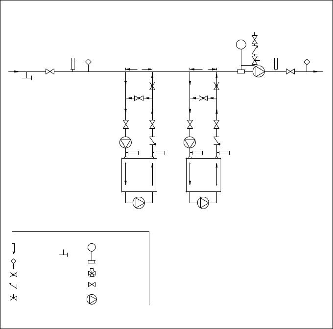
Suggested piping diagrams are shown in Figures 4 through 8. These diagrams are meant only as a guide.
|
20°F |
25°F |
30°F |
35°F |
||||
SIZE |
flow |
H/L |
flow |
H/L |
flow |
H/L |
flow |
H/L |
|
gpm |
feet |
gpm |
feet |
gpm |
feet |
gpm |
feet |
500 |
43 |
1.7 |
34 |
1.1 |
28 |
0.9 |
24 |
0.7 |
750 |
64 |
3.3 |
51 |
2.3 |
43 |
1.7 |
36 |
1.2 |
1000 |
85 |
5.0 |
68 |
3.6 |
57 |
3.1 |
49 |
2.2 |
1250 |
106 |
8.1 |
85 |
6.1 |
71 |
4.7 |
61 |
3.4 |
1500 |
128 |
10.0 |
102 |
7.2 |
85 |
5.5 |
73 |
4.2 |
1750 |
N/R |
N/R |
119 |
10.5 |
99 |
8.4 |
85 |
5.8 |
2000 |
N/R |
N/R |
136 |
12.5 |
113 |
10.4 |
97 |
8.3 |
Metric Equivalent |
|
|
|
|
|
|
||
|
11°C |
14°C |
17°C |
19°C |
||||
SIZE |
flow |
H/L |
flow |
H/L |
flow |
H/L |
flow |
H/L |
|
lpm |
m |
lpm |
m |
lpm |
m |
lpm |
m |
500 |
161 |
0.5 |
129 |
0.3 |
107 |
0.3 |
92 |
0.2 |
750 |
241 |
1.0 |
193 |
0.7 |
161 |
0.5 |
138 |
0.4 |
1000 |
321 |
1.5 |
257 |
1.1 |
214 |
0.9 |
184 |
0.7 |
1250 |
401 |
2.5 |
322 |
1.9 |
269 |
1.4 |
231 |
1.0 |
1500 |
483 |
3.0 |
386 |
2.2 |
322 |
1.7 |
276 |
1.3 |
1750 |
N/R |
N/R |
451 |
3.2 |
375 |
2.6 |
322 |
1.8 |
2000 |
N/R |
N/R |
515 |
3.8 |
429 |
3.2 |
368 |
2.5 |
Notes: gpm = gallons per minute, lpm = liters per minute,
H/L = headloss, ft = headloss in feet, m = headloss in meters. Maximum temperature rise is 35°F (19°C), as shown. Headloss is for boiler’s heat exchanger only.
N/R = not recommended.
Table 8. Water Flow Requirements - PNCH.
Components required by local codes must be properly installed.
Note the recommended location of the temperature sensor on the diagrams; you must provide a location for the additional sensor shipped with the
Pennant. This sensor may be strapped onto pipe from 1" to 4" diameter, or inserted into an immersion well.
4A.2 Cold Water Make-Up — Boiler
1.Connect the cold water supply to the inlet connection of an automatic fill valve.
2.Install a suitable back flow preventer between the automatic fill valve and the cold water supply.
3.Install shut off valves where required.
NOTE: The boiler, when used in connection with a refrigeration system, must be installed so the chilled medium is piped in parallel with the boiler with appropriate valves to prevent the chilled medium from entering the boiler.
The boiler piping system of a hot water heating boiler connected to heating coils located in air handling appliances where they may be exposed to refrigerated air circulation must be equipped with flow control valves or other automatic means to prevent gravity circulation of the boiler water during the cooling cycle.
A boiler installed above radiation level, or as required by the authority having jurisdiction, must be provided with a low water cutoff device either as a part of the boiler or at the time of boiler installation.
4A.3 Water Flow Requirements — Boiler
A hydronic heating (closed loop) application re-circulates the same fluid in the piping system. As a result, no new minerals or oxygen is introduced into the system. To ensure a proper operating temperature leading to long boiler life, a flow rate has been established based on the fluid temperature rise for this specific size boiler.
Pump-mounted boilers can be ordered for use in primary secondary piping systems. The pumps used are sized for the headloss through the heater, plus 30 feet (9.1m) of full-sized piping (same size as boiler outlet) and a normal number of fittings.
Table 8 specifies water flow rates for boilers, which will enable the user to size a pump. The headloss shown is for the heater only, and the user will need to add the headloss of the system piping to properly size the pump.
The minimum inlet water temperature for the
Pennant is 120°F (49°C) to avoid condensing on the copper coils.

Pennant (500-2000) |
Page 15 |
|
|
|
|
COLD WATER
MAKE-UP
SYSTEM
RETURN
C C
SYSTEM PUMP |
SYSTEM |
|
SUPPLY |
||
|
PUMP LOCATION FOR
NON-PUMP-MOUNTED UNITS
CAUTION: THIS DRAWING SHOWS SUGGESTED |
|
|
PIPING CONFIGURATION AND VALVING, CHECK |
PUMP LOCATION FOR PUMP-MOUNTED UNITS |
|
WITH LOCAL CODES AND ORDINANCES FOR |
||
|
||
ADDITIONAL REQUIREMENTS. |
|
|
|
PRIMARY/SECONDARY MANDITORY FOR ALL |
|
|
VARIABLE FLOW SYSTEMS |
|
LEGEND |
INSTALL AIR VENTS AT HIGH POINTS IN SYSTEM |
|
PIPING & SIZING OF EXPANSION TANK |
||
|
THERMOMETER |
EXPANSION TANK |
PER TANK MANUFACTURER'S INSTRUCTIONS |
|
WITH AIR SCOOP AND |
DIMENSION "C" (COMMON PIPING) TO BE FOUR |
||
|
|||
|
AUTO AIR VENT |
PIPE DIAMETERS, MAX. (NO ELBOWS OR VALVES) |
|
TEMPERATURE |
PURGE |
BOILER CIRCUIT PIPING MUST BE EQUAL |
|
VALVE |
|||
SENSOR |
TO BOILER WATER CONNECTION SIZE |
||
|
|||
GLOBE VALVE |
3-WAY VALVE |
BOILER CIRC. PUMP SIZED FOR FLOW THROUGH BOILER |
|
|
|||
|
DOTTED DEVICES INDICATE ALTERNATE LOCATIONS |
||
|
|
CHECK VALVE |
VALVE |
|
|
PRESSURE REDUCING VALVE |
|
W/ FAST FILL BYPASS |
PUMP |
PUT BOILER CONTROL SENSOR IN THE SYSTEM SUPPLY WHEN USING THIS PIPING STYLE.
MINIMUM BOILER INLET WATER TEMPERATURE MUST BE AT LEAST 120°F.
Figure 4. Hydronic Piping — Multiple Boilers, Primary Secondary System.
4A.4 Freeze Protection — Boiler
Boiler installations are not recommended in areas where the danger of freezing exists unless proper precautions are made for freeze protection. A non toxic, heating system, anti-freeze may be added to the hydronic system provided that the concentration does not exceed 50% and the anti freeze contains an anti foamant. When a 50/50 mixture is used, increase the water flow requirements by 15%, and increase the headloss requirements by 20%.
Power outage, interruption of gas supply, failure of system components, activation of safety devices, etc., may prevent a boiler from firing. Any time a boiler is subjected to freezing conditions, and the boiler is not able to fire, and/or the water is not able to circulate, there is a risk of freezing in the boiler
or in the pipes in the system. When water freezes, it expands. This can result in bursting of pipes in the system, or damage to the boiler, which could result in leaking or flooding conditions.
IMPORTANT NOTES: Different glycol products may provide varying degrees of protection. Glycol products must be maintained properly in a heating system, or they may become ineffective. Consult the glycol specifications, or the glycol manufacturer, for information about specific products, maintenance of solutions, and set up according to your particular conditions.
Page 16 |
LAARS Heating Systems |
|
|
|
|
COLD WATER
MAKE-UP
|
C |
C |
|
|
|
|
SYSTEM |
SYSTEM |
|
SYSTEM PUMP |
SUPPLY |
|
|
||
RETURN |
B |
B |
|
|
A |
A |
|
|
|
ADJUSTMENT PROCEDURE TO MAINTAIN |
|
|
|
120°F INLET TEMP: |
|
|
|
1. Turn on boiler and open valves A & B. |
|
|
|
2. After steady-state operation, if T1 is less than |
|
|
|
120°F, slowly close valve B until T1 climbs to |
|
|
|
120°F. |
|
|
|
3. If T1 is greater than 120°F, slowly close |
|
|
|
valve A until T1 drops to 120°F. |
|
|
PUMP LOCATION FOR |
4. Check after system operating temperature |
|
|
NON-PUMP-MOUNTED UNITS |
has stabilized. Make final adjustments. |
|
|
T1 |
T1 |
|
CAUTION: THIS DRAWING SHOWS SUGGESTED |
|
|
||
PIPING CONFIGURATION AND VALVING, CHECK |
PUMP LOCATION FOR PUMP-MOUNTED UNITS |
|||
WITH LOCAL CODES AND ORDINANCES FOR |
||||
ADDITIONAL REQUIREMENTS. |
|
|
PRIMARY/SECONDARY MANDITORY FOR ALL |
|
|
|
|
|
|
|
|
|
|
VARIABLE FLOW SYSTEMS |
|
|
|
|
INSTALL AIR VENTS AT HIGH POINTS IN SYSTEM |
LEGEND |
|
|
PIPING & SIZING OF EXPANSION TANK |
|
|
|
|
|
|
|
|
EXPANSION TANK |
PER TANK MANUFACTURER'S INSTRUCTIONS |
|
THERMOMETER |
|
DIMENSION "C" (COMMON PIPING) TO BE FOUR |
||
|
WITH AIR SCOOP AND |
|||
|
|
|||
|
|
PIPE DIAMETERS, MAX. (NO ELBOWS OR VALVES) |
||
|
|
AUTO AIR VENT |
||
TEMPERATURE |
PURGE |
|
|
|
VALVE |
|
|
BOILER CIRCUIT PIPING MUST BE EQUAL |
|
SENSOR |
|
|
||
|
|
3-WAY VALVE |
TO BOILER WATER CONNECTION SIZE |
|
GLOBE VALVE |
|
BOILER CIRC. PUMP SIZED FOR FLOW THROUGH BOILER |
||
|
|
|
||
|
|
|
|
|
CHECK VALVE |
|
VALVE |
|
DOTTED DEVICES INDICATE ALTERNATE LOCATIONS |
|
|
|
||
|
|
|
PUT BOILER CONTROL SENSOR IN THE SYSTEM |
|
|
|
|
|
|
PRESSURE REDUCING VALVE |
|
|
SUPPLY WHEN USING THIS PIPING STYLE. |
|
|
|
|
||
W/ FAST FILL BYPASS |
PUMP |
|
MINIMUM BOILER INLET WATER TEMPERATURE |
|
|
|
|
|
MUST BE AT LEAST 120°F. |
Figure 5. Hydronic Piping — Multiple Boilers, Low Temperature System.

Pennant (500-2000) |
Page 17 |
|
|
|
|
150°F
C
|
|
|
COLD WATER |
|
|
|
|
MAKE-UP |
|
C |
|
|
C |
180°F |
130°F |
|
|
|
|
|
|
C |
180°F |
|
|
|
|
|
|
|
|
|
SYSTEM PUMP |
|
|
|
|
NOTES: |
|
|
PUMP LOCATION FOR |
|
1. BOILER LOOP IN EXAMPLE IS MAINTAINED AT 180°F. |
|
|
|
2. ZONE THERMOSTATS CAN BE INTERLOCKED WITH BOILER, |
||
|
NON-PUMP-MOUNTED UNITS |
|
||
|
|
SO THAT BOILER FIRES UPON CALL FOR HEAT FROM ANY |
||
|
|
|
||
|
|
|
ZONE. |
|
|
|
|
3. ZONE PIPING AND INTERLOCK WIRING TO BE DESIGNED |
|
|
|
|
BY SYSTEM ENGINEER. |
|
CAUTION: THIS DRAWING SHOWS SUGGESTED
PIPING CONFIGURATION AND VALVING, CHECK PUMP LOCATION FOR PUMP-MOUNTED UNITS
WITH LOCAL CODES AND ORDINANCES FOR
ADDITIONAL REQUIREMENTS.
|
|
|
|
PRIMARY/SECONDARY MANDITORY FOR ALL |
|
|
|
|
VARIABLE FLOW SYSTEMS |
LEGEND |
|
|
INSTALL AIR VENTS AT HIGH POINTS IN SYSTEM |
|
|
|
|
||
|
|
|
|
PIPING & SIZING OF EXPANSION TANK |
THERMOMETER |
|
EXPANSION TANK |
PER TANK MANUFACTURER'S INSTRUCTIONS |
|
|
|
|||
|
WITH AIR SCOOP AND |
DIMENSION "C" (COMMON PIPING) TO BE FOUR |
||
|
|
|||
|
|
AUTO AIR VENT |
PIPE DIAMETERS, MAX. (NO ELBOWS OR VALVES) |
|
|
PURGE |
|
|
|
TEMPERATURE |
|
|
|
|
VALVE |
|
|
BOILER CIRCUIT PIPING MUST BE EQUAL |
|
SENSOR |
|
|
||
|
|
|
TO BOILER WATER CONNECTION SIZE |
|
|
|
|
|
|
GLOBE VALVE |
3-WAY VALVE |
|
|
CHECK VALVE |
VALVE |
|
|
PRESSURE REDUCING VALVE |
|
W/ FAST FILL BYPASS |
PUMP |
BOILER CIRC. PUMP SIZED FOR FLOW THROUGH BOILER
DOTTED DEVICES INDICATE ALTERNATE LOCATIONS
PUT BOILER CONTROL SENSOR IN THE SYSTEM SUPPLY WHEN USING THIS PIPING STYLE.
MINIMUM BOILER INLET WATER TEMPERATURE MUST BE AT LEAST 120°F.
Figure 6. Hydronic Piping — One Boiler, Multi-Temperature System.
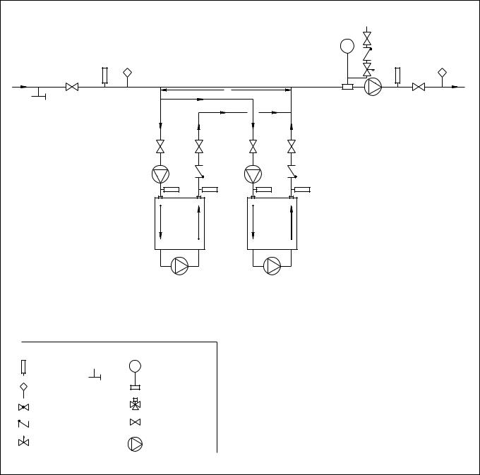
Page 18 |
LAARS Heating Systems |
|
|
|
|
COLD WATER
MAKE-UP
SYSTEM
RETURN
C
SYSTEM PUMP
PUMP LOCATION FOR
NON-PUMP-MOUNTED UNITS
PUMP LOCATION FOR PUMP-MOUNTED UNITS
CAUTION: THIS DRAWING SHOWS SUGGESTED |
PRIMARY/SECONDARY MANDITORY FOR ALL |
|
VARIABLE FLOW SYSTEMS |
||
PIPING CONFIGURATION AND VALVING, CHECK |
||
|
||
WITH LOCAL CODES AND ORDINANCES FOR |
INSTALL AIR VENTS AT HIGH POINTS IN SYSTEM |
|
ADDITIONAL REQUIREMENTS. |
||
|
PIPING & SIZING OF EXPANSION TANK
PER TANK MANUFACTURER'S INSTRUCTIONS
LEGEND |
||
THERMOMETER |
|
|
TEMPERATURE |
PURGE |
|
VALVE |
||
SENSOR |
||
|
||
GLOBE VALVE |
|
|
CHECK VALVE |
|
|
PRESSURE REDUCING VALVE W/ FAST FILL BYPASS
EXPANSION TANK
WITH AIR SCOOP AND AUTO AIR VENT
3-WAY VALVE
VALVE
PUMP
DIMENSION "C" (COMMON PIPING) TO BE FOUR PIPE DIAMETERS, MAX. (NO ELBOWS OR VALVES)
BOILER CIRCUIT PIPING MUST BE EQUAL
TO BOILER WATER CONNECTION SIZE
BOILER CIRC. PUMP SIZED FOR FLOW THROUGH BOILER
DOTTED DEVICES INDICATE ALTERNATE LOCATIONS
PUT BOILER CONTROL SENSOR IN THE SYSTEM SUPPLY WHEN USING THIS PIPING STYLE.
MINIMUM BOILER INLET WATER TEMPERATURE MUST BE AT LEAST 120°F.
SYSTEM SUPPLY
Figure 7. Hydronic Piping - Primary-Secondary, Reverse-Return.
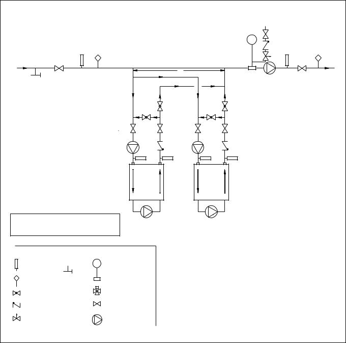
Pennant (500-2000) |
Page 19 |
|
|
|
|
COLD WATER
MAKE-UP
SYSTEM
RETURN
|
C |
|
SYSTEM |
|
|
|
|
|
|
SYSTEM PUMP |
SUPPLY |
|
|
|
|
|
B |
ADJUSTMENT PROCEDURE TO MAINTAIN |
|
B |
120°F INLET TEMP: |
|
|
A |
A |
1. Turn on boiler and open valves A & B. |
|
|
|
2. After steady-state operation, if T1 is less than |
|
|
|
120°F, slowly close valve B until T1 climbs to |
|
|
|
120°F. |
|
|
|
3. If T1 is greater than 120°F, slowly close valve |
|
|
|
A until T1 drops to 120°F. |
|
|
|
4. Check after system operating temperature has |
|
PUMP LOCATION FOR |
|
stabilized. Make final adjustments. |
|
NON-PUMP-MOUNTED UNITS |
|
|
|
T1 |
T1 |
|
|
CAUTION: THIS DRAWING SHOWS SUGGESTED
PIPING CONFIGURATION AND VALVING, CHECK
WITH LOCAL CODES AND ORDINANCES FOR PUMP LOCATION FOR PUMP-MOUNTED UNITS
ADDITIONAL REQUIREMENTS.
PRIMARY/SECONDARY MANDITORY FOR ALL
VARIABLE FLOW SYSTEMS
INSTALL AIR VENTS AT HIGH POINTS IN SYSTEM
LEGEND
|
|
|
PIPING & SIZING OF EXPANSION TANK |
THERMOMETER |
|
EXPANSION TANK |
PER TANK MANUFACTURER'S INSTRUCTIONS |
|
|
||
|
WITH AIR SCOOP AND |
DIMENSION "C" (COMMON PIPING) TO BE FOUR |
|
|
|
||
|
|
AUTO AIR VENT |
PIPE DIAMETERS, MAX. (NO ELBOWS OR VALVES) |
|
PURGE |
|
|
TEMPERATURE |
|
|
|
VALVE |
|
BOILER CIRCUIT PIPING MUST BE EQUAL |
|
SENSOR |
|
||
|
|
|
TO BOILER WATER CONNECTION SIZE |
GLOBE VALVE |
|
3-WAY VALVE |
BOILER CIRC. PUMP SIZED FOR FLOW THROUGH BOILER |
|
|
||
|
|
|
|
CHECK VALVE |
|
VALVE |
DOTTED DEVICES INDICATE ALTERNATE LOCATIONS |
|
|
||
|
|
|
|
|
|
|
PUT BOILER CONTROL SENSOR IN THE SYSTEM |
PRESSURE REDUCING VALVE |
|
SUPPLY WHEN USING THIS PIPING STYLE. |
|
|
|
||
W/ FAST FILL BYPASS |
PUMP |
MINIMUM BOILER INLET WATER TEMPERATURE |
|
|
|
|
|
MUST BE AT LEAST 120°F.
Figure 8. Hydronic Piping - Primary-Secondary, Reverse-Return, Low Temperature.
Page 20 |
LAARS Heating Systems |
|
|
|
|
SECTION 4B.
Water Connections —
Pennant Water Heater
4B.1 Water System Piping —
Water Heater
Hot water piping should be supported by suitable hangers or floor stands. Do not support piping with this appliance. Due to expansion and contraction of copper pipe, consideration should be given to the type of hangers used. Rigid hangers may transmit noise through the system resulting from the piping sliding in the hangers. It is recommended that padding be used when rigid hangers are installed.
The Pennant can be used with several different types of readily available storage tanks. A pump draws water from the storage tank and pumps the water through the heater and back into the tank. Pumpmounted units have a circulating pump built into
the water heater. The pumps used are sized for the headloss through the heater, plus 30 feet (9.1m) of fullsized piping (same size as boiler outlet) and a normal number of fittings. Pumps used on pump-mounted unit are sized for soft/normal or hard water, so make sure a pump-mounted unit matches the water quality of the installation.
Pipe the outlet from the heater’s relief valve such that any discharge from the relief valve will be conducted to a suitable place for disposal when relief occurs. Do not reduce line size or install any valves in this line. The line must be installed to allow complete drainage of both the valve and the line.
Suggested piping diagrams are shown in Figures 9 through 12. These diagrams are meant only as a guide. Components required by local codes must be properly installed.
Note the recommended location of the temperature sensor on the diagrams. The Pennant is shipped with an additional sensor that can be used for more full-featured domestic water heating control. To get these features, you must provide a location for the additional sensor. It can be strapped to a pipe from 1" to 4" diameter, or inserted into a tank immersion well.
The minimum inlet water temperature for the
Pennant is 120°F (49°C) to avoid condensing on the copper coils.
4B.2 Hot Water Supply Piping —
Water Heater
Follow the tank manufacturer’s guidelines for completion of the hot water system connections.
NOTE: A listed temperature and pressure relief valve listed as complying with the Standard for Relief Valves and Automatic Gas Shutoff Devices for Hot Water Supply Systems (ANSI Z21.22 / CSA 4.4) of suitable discharge capacity must be installed in the separate storage tank system.
If the Pennant water heater is installed in a closed water supply system, such as one having a backflow preventer in the cold water supply line, the relief valve may discharge periodically, due to thermal expansion. Means (such as a properly-sized expansion tank) shall be provided to control thermal expansion. Contact the water supplier or local plumbing inspector on how to control this situation.
4B.3 Water Flow Requirements —
Water Heater
In a water heating application (an open system), new water is constantly being introduced. With the new water comes a fresh supply of minerals that can be deposited on the unit’s heat exchanger. This is commonly known as scaling. The amount of minerals will depend upon the hardness of the water. Water can also be aggressive, and can erode metals, including copper, if the water is moved too quickly. The water flow requirements for the Pennant water heater are based upon the hardness of the water. The water flow is kept high enough to prevent scaling, but low enough to prevent tube erosion. For extremely soft or hard water, cupro-nickel tubes are available. Contact a
Laars Representative if you have questions or concerns about water quality.
Pump-mounted water heaters can be ordered with standard pumps for soft or normal water or with pumps for hard water. The pumps used are sized for the headloss through the heater, plus 30 feet (9.1m) of full-sized piping (same size as heater outlet) and a normal number of fittings.
Table 9 specifies water flow rates for water heaters, which will enable the user to size a pump.
The headloss shown is for the heater only, and the user will need to add the headloss of the piping system to properly size the pump.
4B.4 Combined Water Heating (potable) and Space Heating — Water Heater
NOTE: These systems are not allowed in the Commonwealth of Massachusetts.
Piping and components connected to this water heater for the space heating application shall be suitable for use with potable water.
Toxic chemicals, such as used for boiler treatment, shall not be introduced into the potable water used for space heating.
This water heater when used to supply potable water shall not be connected to any heating system or component(s) previously used with a non-potable water heating appliance.
When the system requires water for heating at temperatures higher than required for other uses, an anti-scald mixing or tempering valve shall be installed to temper the water for those uses in order to reduce scald hazard potential.
 Loading...