

Page 1
Installation, Operation and Maintenance Instructions Document 1100C
Installation,
Operation and
Maintenance
Instructions for
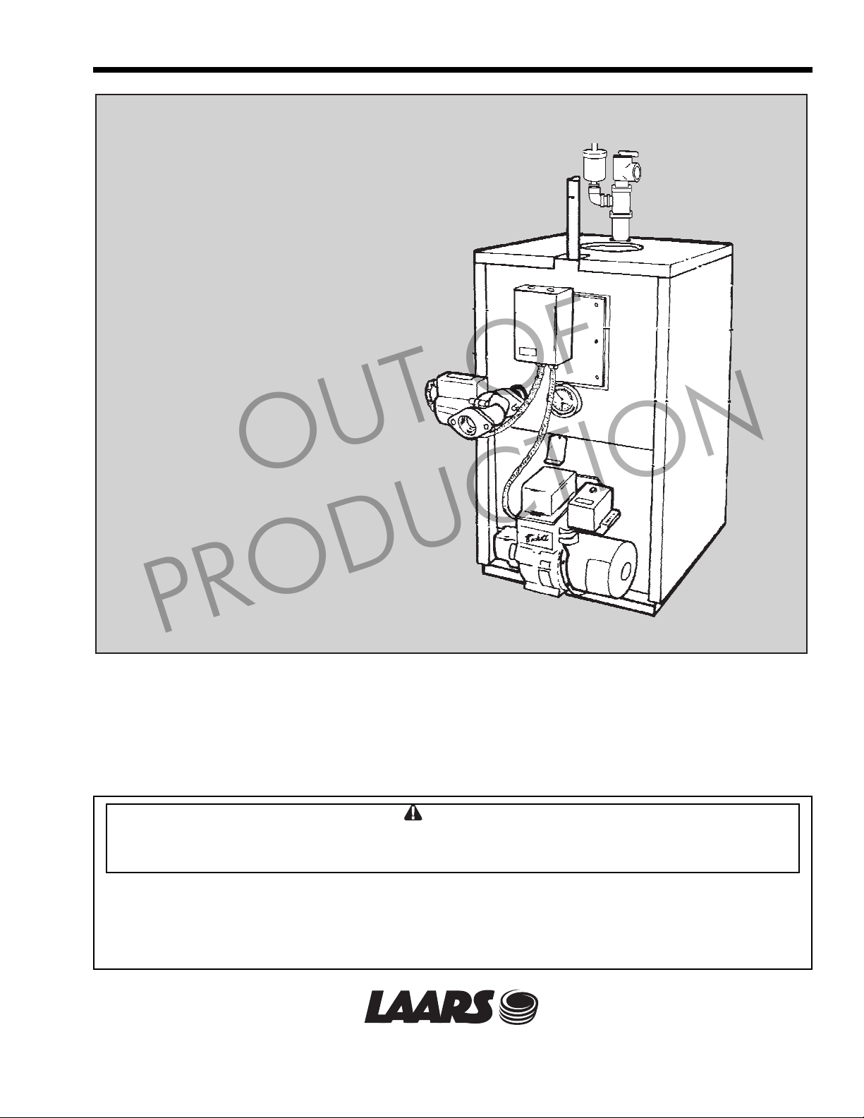
Newport
Oil Fired Boiler
OUT OF
PRODUCTION
FOR YOUR SAFETY: This product must be installed and serviced by a professional service technician,
qualified in boiler installation and maintenance. Improper installation and/or operation could create
carbon monoxide gas in flue gases which could cause serious injury, property damage, or death.
Improper installation and/or operation will void the warranty.
WARNING
If the information in this manual is not followed exactly, a fire or explosion may result causing
property damage, personal injury or loss of life.
Do not store or use gasoline or other flammable vapors and liquids in the vicinity of this or any other
appliance.
Installation and service must be performed by a qualified installer, service agency, or fuel oil supplier.
®
Heating Systems Company
A subsidiary of CorporationBRADFORD WHITE
52-206C
®
Page 2

Page 2
LAARS Heating Systems
TABLE OF CONTENTS
SECTION 1.
General Information
1.1 Boiler Installation ...........................................3
1.2 Freight Claims ...............................................3
1.3 Boiler Location............................................... 3
1.4 Boiler Clearances (to combustibles).............. 3
1.5 Floor ..............................................................3
1.6 Combustion and Ventilation Air .....................3
1.7 Chimney and Draft Requirements ................. 3
1.8 Jacket (normally fi tted) ..................................4
1.9 Oil Burner (normally fi tted)............................. 4
1.10 Installation of Alternate Nozzles
for Higher Output........................................ 4
1.11 Boiler Controls (normally fi tted) ..................... 3
1.12 Oil ..................................................................3
1.13 Oil Storage and Pipe Layout..........................3
OUT OF
1.14 Electrical Wiring............................................. 4
1.15 Operation
(Honeywell L.8124A or L7224A aquastat
relay)...........................................................4
1.16 Domestic Water Piping.................................. 4
1.17 Cleaning the Boiler ........................................5
1.18 Cleaning the Chimney ...................................6
1.19 Servicing the Burner...................................... 6
1.20 Maintenance of the Tankless Coil .................6
1.21 Coil Removal .................................................6
SECTION 2.
Replacement Parts
2.1 Ordering Information....................................11
2.2 Parts List......................................................11
PRODUCTION
Page 3

Newport Oil-Fired Heater
Page 3
SECTION 1.
General Information
Newport boilers have been designed and
con struct ed ac cord ing to ASME codes using heavy
gauge steel tubes and boiler plate.
The reliable heat exchanger incorporates special
flue baffles to assure quiet and efficient operation and
a pur pose designed ceraform combustion cham ber
min i miz es base loss and also provides a tight enclosure
with the heat exchanger.
The domestic hot water coil is located at the top
of the boiler in the hottest zone for an ample supply
of hot wa ter. A unique feature of its attachment is the
raised coil flange which allows the use of clamping
bolts rather than studs, thereby elim i nat ing water leaks
caused by broken studs.
The complete unit comes pre-assembled for easy
in stal la tion and is encased by a fully insulated baked
enamel jacket.
As delivered, the boiler's burner is equipped with
a nozzle for 0.85 (NP 85-110) or 1.25 (NP 125-150)
gallons of #2 heating oil. Provided with the boiler are
two (2) additional nozzles that permit higher firing
rates. See Table 1 below.
Installation of either of the two (2) additional
nozzles, in place of the factory-installed nozzle, will
provide the corresponding performance indicated in
the chart labeled “Performance”, on page 7, for the
alternate nozzle installed. Boilers equipped with Carlin
burners also require a change of the Head Positioning
Bar (also provided).
PRODUCTION
OUT OF
1.3 Boiler Location
The boiler should be positioned as near to the
chim ney as possible and have a minimum smoke pipe
connector length of 18"(457mm).
CAUTION
Newport boilers must not be directly connected
to a heating system using oxygen permeable
tubing (see warranty). Use a water to water
heat exchanger between boiler and system to
prevent corrosion.
1.4 Boiler Clearances (to combustibles)
Top - 6" (152mm) Front - 24" (610mm)
Rear - 6" (152mm) Sides - 6" (152mm)
1.5 Floor
The boiler must be mounted on a noncombustible
ma son ry or cement floor with no com bus ti bles
un der neath.
1.6 Combustion and Ventilation Air
To insure an adequate supply of fresh air for
com bus tion and ventilation an inlet and outlet opening
should be pro vid ed at floor and ceiling level. Each
opening must have a minimum of one square inch
(16.5 sq. cm) of free area for every 1,000 BTU/h
(293kW) of input or 140 square inches (903 sq. cm)
per one gallon (3.785L) of oil burned per hour. The
openings must not be in a position liable to blockage.
1.1 Boiler Installation
For recommended installation practice reference
should be made to the National Fire Protection
Stan dard for Oil Burning Equipment (NFPA 31 Latest Edition).
1.2 Freight Claims
Inspection should be made of boiler and its
com po nents for damage upon arrival. Any claims for
damage should immediately be filed against the carrier
by the consignee.
BURNER
Beckett AFG NP 85 -110 1.00 Delavan 1.00 x 80A 100
Beckett AFG NP 85 -110 1.10 Delavan 1.10 x 70A 100
Beckett AFG NP 125 - 150 1.35 Delavan 1.35 x 80A 100
Beckett AFG NP 125 - 150 1.50 Delavan 1.50 x 80A 100
Carlin EZ -1 NP 85 -110 1.00 Delavan 0.85 x 60B 140 0.85-1.00
Carlin EZ -1 NP 85 -110 1.10 Delavan 0.90 x 60B 150 0.85-1.00
Carlin EZ -1 NP 125 - 150 1.35 Delavan 1.10 x 60B 150 1.10-1.25
Carlin EZ -1 NP 125 - 150 1.50 Delavan 1.25 x 60B 145 1.10-1.25
BOILER
MODEL
DESIRED INPUT
(GPH)
Table 1 - Specifications for additional nozzles
1.7 Chimney and Draft Requirements
To assure the safe and proper operation of the
oil burner the boiler must be connected to a chimney
having suf fi cient draft at all times to evacuate the
flue gases to at mo sphere. A draft regulator must be
installed in the smoke-pipe as near to the flue as
possible and adjusted to achieve an overfire draft of
0.01 ins. W.C.
NOZZLE
PUMP PRESSURE
(PSI)
HEAD POSITIONING
BAR
Page 4

Page 4
LAARS Heating Systems
1.8 Jacket (normally fitted)
If not fitted, assemble panels in accordance with
in struc tions in Figure 4.
1.9 Oil Burner (normally fitted)
If not fitted, insert burner tube into boiler so
that it is ap prox i mate ly ¼" (6mm) from inside wall of
ceraform chamber, then clamp mounting flange and
bolt up to front-plate (see Figure 3).
The burner should be wired and connected to
the oil line in accordance with the manufacturer’s
instructions.
1.10 Installation of Alternate Nozzles for
Higher Output
This operation shall only be carried out by a
trained and licensed Service Technician in accordance
with the burner manufacturer’s instructions included in
the literature package provided with this boiler.
1.11 Boiler Controls (normally fitted)
If controls are supplied separately, fit them to the
boiler in the positions shown in Figure 3, with jacket
in place.
Circulator - 1¼" return tapping at front of boiler.
Tridicator - temp/press. gauge.
Relief Valve - Provide ¾" tee and auto vent as
shown on front page for air elimination.
Aquastat Relay - L8124A or L7224A - ¾"
tapping in coil plate.
Fit a drain valve (not supplied) in a tee at
hy dron ic return connection and check all connections
are made wa ter tight.
1.12 Oil
USE ONLY No. 2 HEATING OIL. Do not use
gasoline, crankcase draining or any oil con tain ing
gasoline.
1.13 Oil Storage and Pipe Layout
Storage Tank: Consult local fire and building
codes for acceptable fuel storage methods in your area.
B
O
I
L
E
R
Figure 1. Domestic water piping.
11
PRODUCTION
(76mm - 152mm)
OUT OF
13
3 - 6"
12
Fuel Line: A single pipe system of not less
than 3/8" OD copper tubing is recommended when
fuel storage level is not below the fuel unit. A two
pipe system of not less than 3/8" OD copper tubing is
recommended when lowest fuel level is below but not
more than 8 feet below fuel unit.
Important: Refer to burner (pump) instructions
for detailed fuel line and pump usage information. All
installations must conform to local and national codes.
See Figures 5A and 5B.
Figure 5A One-pipe system - pipe and tank
layout.
Figure 5B Two-pipe system - pipe and tank
layout.
1.14 Electrical Wiring
All wiring must comply with the National
Electrical Code, NFPA 70, local codes and ordinances
regarding wire size, type of insulation and enclosures
etc. (see Figure 6).
1.15 Operation (Honeywell L8124A or
L7224A aquastat relay)
A call for heat from the room thermostat causes
the re lay to “make “ the burner circuit and also feed
the cir cu la tor provided the boiler water tem per a ture is
above the low limit setting (usually 190°F [88°C] to
210°F [99°C]). The burner and cir cu la tor then continue
to run until the room thermostat is satisfied.
A high limit switch shuts off burner in the event
of water temperature exceeding the high limit setting,
usually 20°F (-7°C) to 30°F (-1°C) above the low limit
setting.
The low limit switch and circulator maintain
boiler water temperature for domestic hot water
ser vic es and pre vent circulation of heating system
water if domestic water is not hot enough.
1.16 Domestic Water Piping
1. Connect anti scald tempering valve (12) “HOT”
port to hot water outlet from unit. This valve
should be mounted 3" (76mm) to 6" (152mm)
below the outlet and set for 120° F mixed
delivery temperature or as local codes dictate
(see Figure 1).
2. Connect gate or shutoff valve (13) to anti scald
tempering valve (12) “MIX” port, and another to
the cold water inlet.
3. Connect pressure relief valve (11) (if required
by codes), maximum 150 PSI as close to the unit
as possible. No other valves or restrictions may
be installed between the DHW coil and the
relief valve.
(DO NOT USE A TEM PER A TURE/PRES SURE
RELIEF VALVE AS THIS IS NOT A STOR AGE
HOT WATER HEATER).
Page 5

Newport Oil-Fired Heater
Page 5
WARNING
Flue gases are dangerous - do not operate
boiler if there is an escape of flue gas. Call a
qualified serviceman and have the entire flue
and venting system inspected.
1.17 Cleaning the Boiler
To maintain the high thermal efficiency and
a long life from your boiler, it should be cleaned at
least once a year, preferably at the end of the heating
season. This is particularly important as rusting can
occur when the boiler is idle.
AIR VENT
HYDRONIC
SUPPLY PIPE
OUT OF
It is recommended that a service contract be
ar ranged with a properly equipped serviceman who
will be able to do the job efficiently and without mess.
1. Switch off electrical supply to the boiler.
2. Remove smoke-pipe from boiler.
3. Remove top jacket panel.
4. Unscrew the securing nuts and remove flue
col lec tor.
5. Remove baffles from flue tubes.
6. Remove burner by unscrewing the flange
mounting nuts.
PRESSURE RELIEF VALVE
FLUE CONNECTION
AQUASTAT RELAY
L8124A OR L7224A
¾" NPT
WIRING CONDUIT
PRODUCTION
CIRCULATOR 1¼" NPT
BURNER
TANKLESS DO MES TIC
HOT WATER COIL
½" NPT
TRIDICATOR
FLAME VIEWING
PORT
Tapping NPT
Tankless Coil ½"
Tridicator ¼"
Hydronic Return 1¼"
Figure 2. Components Location.
Hydronic Supply 1¼"
Aquastat Well ¾"
Relief Valve Fitting ¾"
Page 6

Page 6
LAARS Heating Systems
7. Remove soot and scale deposits from tubes with
a flexible wire brush, taking care not to damage
“ceraform” combustion chamber, below outer
tubes.
8. Vacuum out accumulated deposits from
combustion chamber through burner port, taking
care not to damage “ceraform” combustion
chamber.
9. Replace all parts, ensuring flue-baffles are
correctly located. Ensure flue collector and
smoke-pipe are tightly sealed.
1.18 Cleaning the Chimney
Sweep all soot deposits from chimney and
smoke-pipe once a year, preferably at the end of the
heat ing season. It is also advisable to in spect the
chim ney and smoke-pipe at the be gin ning of heating
season as birds may have built their nest inside or
other material may be caus ing a blockage.
1.19 Servicing the Burner
This should only be carried out by a trained and
licensed service technician in accordance with the
burner mak er’s instructions.
OUT OF
1.20 Maintenance of the Tankless Coil
After several years of use, the water flow through
the coil may become restricted by mineral deposits
from the water. Mild accumulations may be removed
by an acid treatment but your servicing company can
advise on the most satisfactory method of clean ing or
whether a re place ment coil is necessary.
1.21 Coil Removal
1. Switch off electrical supply and turn off water to
boil er.
2. Valve off zones and drain boiler and DHW coil.
3. Disconnect the pipe connections to the coil.
4. Unscrew the eight retaining bolts from coil plate.
5. Pull out coil and clean or fit replacement as
necessary.
6. Ensure gasket makes a water tight seal.
7. Refill boiler, open valves and check for leaks.
Domestic
Water Out
(Hot)
PRODUCTION
Domestic
Water In
(Cold)
SIDE
FRONT
Figure 3. Dimensions.
Page 7

Newport Oil-Fired Heater
Dimensions and Specifi cations
NP 85 - 110 NP 125 - 150
REF
Jacket Height A 35½ 90 41 104
Jacket Width B 19¼ 49 20½ 52
Jacket Length C 20 51 21½ 55
Return Tapping Height D 19½ 50 22 56
Supply Tapping E 33½ 85 38 97
Coil Supply Height F 27½ 70 31½ 80
Smoke Outlet Diameter G 6 15 6 15
Burner Center Line H 8½ 22 10½ 27
Tankless Coil NPT -- ½ ½
Return NPT -- 1¼ 1¼
Supply NPT -- 1¼ 1¼
Shipping Weight - lbs. kg -- 310 141 368 167
Water Content - Gallons L -- 11.6 44 15.4 58
Coil Size GPM -- 5--5--
inches cm inches cm
Page 7
OUT OF
Performance
Model NP 85-110 NP 125 - 150
Firing Rate GPH 0.85 -- 1.00 -- 1.10 -- 1.25 -- 1.35 -- 1.50 --
Input MBTU/hr kW 103 30 120 35 133 30 150 44 160 47 177 52
Output MBTU/hr kW 90 26 105 30 116 34 130 38 139 40 154 48
Effi ciency % AFUE 83.6 83.1 83.1 83.7 83.0 83.0
Net Stack Temperature °F °C 312 156 353 178 371 188 351 177 386 197 417 214
PRODUCTION
Beckett Burner Specifi cations
AFG Burner Purchased to Beckett Spec. #TRI-801 For NP Units
Boiler Model NP 85 - 110 NP 125 - 150
Burner AFG AFG
Nozzle (Factory Installed) .85 x 70° A 1.25 x 80° A
Nozzle Manufacturer Delavan Delavan
Static Plate 3-3/8 3-3/8
Head Type F3 F6
Pump Pressure 100 100
Carlin Burner Specifi cations
Boiler Model NP 85 - 110 NP 125 - 150
Burner EZ - 1 EZ - 1
Nozzle (Factory Installed) .70 x 60A 1.00 x 60B
Nozzle Manufacturer Delavan Delavan
Head Positioning Bar * 0.6-0.65 0.85-1.00
Pump Pressure - PSI 145 150
* Head Positioning Bar must be changed when changing to an alternate nozzle
Page 8

Page 8
LAARS Heating Systems
OUT OF
PRODUCTION
Instructions
1. Pre-assemble L/H side (1) and R/H side (2) to front panel (3) with screws.
2. Slide assembled jacket over boiler and secure side panels to base tray.
3. Fix rear panel (4) to sides.
4. Adjust corner brackets (5) on heat exchanger so they touch inside of jacket and secure.
5. Fit top panel (6) over jacket.
Figure 4. Jacket assembly.
Page 9

Newport Oil-Fired Heater
Page 9
Air vent
Fill pipe
Valve
Figure 5A
OUT OF
Air vent 1¼" min.
Fill pipe
1¼" min.
Oil tank
Filter
"H"
Valve
"P"
Filter
Burner
Burner
Boiler
Boiler
One-Pipe
System
Two-Pipe
System
Oil
PRODUCTION
Figure 5B
PIPE LENGTHS
One Pipe Gravity System
"H"
3/8" O.D. 1/2" O.D.
ft. m ft. m ft. m
0 0 0 0 0 0
1½ 0.5 33 10.1 65 19.8
3 0.9 65 19.8 130 39.6
5 1.5 130 39.6 260 79.2
6½ 2 195 59.4 325 99
WARNING:- The height should not exceed 13 feet (4m)
WARNING:- The vacuum must not exceed 11.44 HG. (11.44
inches of Mercury). Burner is shipped from the factory set up
for two pipe system.
Important:- An external fi lter must be placed in the fuel line
between the fuel tank and the burner pump.
tank
"H"
PIPE LENGTHS
Two Pipe Gravity System
"H"
3/8" O.D. 1/2" O.D.
ft. m ft. m ft. m
0 0 0 0 0 0
1½ 0.5 115 33.0 330 100.6
3 0.9 100 30.5 330 100.6
5 1.5 80 24.4 330 100.6
6½ 2 50 15.2 295 89.9
9½ 2.9 25 7.6 100 30.5
11 3.4 20 6.1 65 19.8
Figure 5. Piping information.
Page 10

Page 10
LAARS Heating Systems
Power supply provides disconnect means & overload protection as required.
24V
Room Thermostat
L1 (Hot)
Power Supply
120V
1K
L2
OUT OF
Circulator
Switch
1K1
Low Limit
Circulator
PRODUCTION
Hi Limit
1K2
Oil Burner
Relay
Figure 6. Wiring diagram.
Heating Circulator
AQUASTAT RELAY L8124A
WIRING ARRANGEMENT FOR “NP” BOILER
CONTROLLING OPERATION OF BOILER AND CIRCULATOR
Page 11

Newport Oil-Fired Heater
SECTION 2.
Replacement Parts
2.1 Ordering Information
To order or purchase parts for Laars products,
contact your nearest Laars dealer of distributor. If they
cannot supply you with what you need, contact Laars
Customer Service at the address shown on the back
cover of this manual.
Visit our website at www.Laars.com for Service
Center listings.
2.2 Parts List
Page 11
Part Number Description Size
52-002 Boiler Body ................................... 85/110
51-056 Base Assembly ............................ 85/110
(after 1990 - includes 51-058 panel)
51-058 Burner Panel Assembly ................ 85/110
Use with P/N 51-056
51-090 Flue Cover Assembly.................... 85/110
52-108 Front Panel Assembly .................. 85/110
52-116 Left Panel Assembly..................... 85/110
52-124 Right Panel Assembly .................. 85/110
51-128 Top Panel Assembly..................... 85/110
52-136 Rear Panel Assembly ................... 85/110
51-088 Chamber....................................... 85/110
51-053 Baffle, 85-115 (14), 125-155 (18),
175-200 (30) .................................... All
OUT OF
PRODUCTION
Part Number Description Size
54-002 Boiler Body ................................. 125/150
53-056 Base Assembly .......................... 125/150
(after 1990 - includes 53-058 panel)
53-058 Burner Panel Assembly ............. 125/155
Use with p/n 53-0560
53-090 Flue Cover Assembly.................. 125/150
54-108 Front Panel Assembly ................ 125/150
54-116 Left Panel Assembly................... 125/150
54-124 Right Panel Assembly ................ 125/150
53-128 Top Panel Assembly................... 125/155
54-136 Rear Panel Assembly ................. 125/155
53-088 Chamber..................................... 125/150
Page 12

OUT OF
PRODUCTION
®
Heating Systems Company
A subsidiary of CorporationBRADFORD WHITE
®
52-206C
800.900.9276 • Fax 800.559.1583 (Customer Service, Service Advisors)
20 Industrial Way, Rochester, NH 03867 • 603.335.6300 • Fax 603.335.3355
1869 Sismet Road, Mississauga, Ontario, Canada L4W 1W8 • 905.238.0100 • Fax 905.366.0130
www.Laars.com Litho in U.S.A. © Laars Heating Systems 0805 Document 1100C
 Loading...