

Page 1
Installation and Operation Instructions Document 4126D
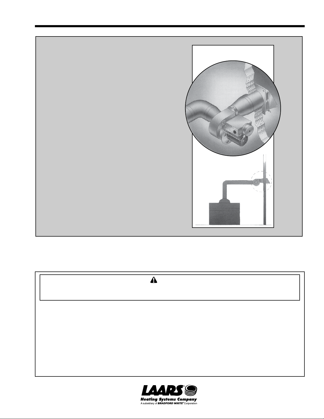
Installation and
Operation Instructions for
Mighty Venter
Power Vent System
Models MV1 and MV2 for
Mighty Therm Sizes 175-400
FOR YOUR SAFETY: This product must be installed and serviced by a professional service technician,
qualified in hot water boiler and vent system installation and maintenance. Improper installation and/or
operation could create carbon monoxide gas in flue gases which could cause serious injury, property
damage, or death. Improper installation and/or operation will void the warranty.
WARNING
If the information in this manual is not followed exactly, a fire or explosion may result
causing property damage, personal injury or loss of life.
Do not store or use gasoline or other flammable vapors and liquids in the vicinity of this or
any other appliance.
WHA T TO DO IF YOU SMELL GAS
• Do not try to light any appliance.
• Do not touch any electrical switch; do not use any phone in your building.
• Immediately call your gas supplier from a nearby phone. Follow the gas supplier's
instructions.
• If you cannot reach your gas supplier, call the fire department.
Installation and service must be performed by a qualified installer, service agency, or gas
supplier.
H0168800D
Page 2

Page 2
LAARS Heating Systems
TABLE OF CONTENTS
SECTION 1.
1a. General Information......................................3
1b. Vent Sizing ...................................................3
1c. Inspection and Unpacking ............................ 3
1d. Installer Information ...................................... 3
1e. Installation Restrictions.................................4
SECTION 2.
Side Wall Vent Hood Location
2a. Side Wall Vent Hood Location ...................... 4
SECTION 3.
Electrical Wiring
3a. Safety Interlock Test.....................................8
3b. Maintenance ................................................. 8
Page 3
Mighty Venter Power Vent System
Page 3
SECTION 1.
1a. General Information
WARNING
The MV1 and MV2 Mighty Venter must be installed
in accordance with the procedures outlined in these
instructions. Warranty applies only if the installation
and operating instructions applicable to the model
purchased are expressly and completely followed.
The Laars Mighty Venter, Models MV1 and
MV2, are designed to make side-wall venting possible
for Laars hot water boilers, Models HH, PH, VW and
PW, sizes 175 - 400. Both the MV1 and MV2 are
equipped with a fan-prover switch which disables the
gas valve if the Power Venter fails to operate.
The Mighty Venter installation must comply with
the latest edition of the National Fuel Gas Code, ANSI
Z223.1, and in Canada, CAN1-B149.1 or .2 and all
local codes that apply. The installation must include
the draft hood assembly shipped with the boiler,
including vent damper if required.
1b. V ent Sizing
Take into consideration the dimensions in Table 1
when designing the vent system. The vent pipe length
shown includes all vent pipe before and after the
Power Venter.
The Mighty Venter kit includes three cartons:
Carton 1. Power Venter (MV1 or MV2)
Carton 2. Vent Hood
Carton 3. Vent Reducers/Adapter
Verify the contents of each carton by checking
against the parts list on page 8.
1d. Installer Information
1. Before beginning the installation, read these
instructions completely and make sure each part
is placed to safely vent flue gases to the
outdoors.
2. Carefully read the installation instructions
located in the Side Wall Vent Hood carton.
3. Laars does not provide the vent pipe necessary
for this installation. Use Table 1 as an aid in
selecting the proper vent pipe diameter.
4. Locate the Power Venter as close as possible to
the point of termination (i.e., the wall). This will
insure the vent pipe between the boiler and the
Power Venter inlet is under negative pressure.
5. Make sure the power supply is adequate for the
Power Venter motor requirements. Do not add
the Power Venter to a circuit where the total load
is unknown.
1c. Inspection and Unpacking
Immediately upon receiving the Mighty Venter
kit, inspect the shipment packaging for damage.
Record any damage on the shipping documents.
To prevent personal injury and equipment damage,
disconnect the power supply to the hot water boiler
when working on the Power Venter.
Caution
Unpack the equipment and carefully inspect it for
obvious damage caused in shipment. If any damage is
found, YOU must file a claim with the transporter. The
transporter will not accept a claim from the shipper,
Laars Heating Systems.
Mighty Boiler/ Mighty Venter Boiler/Heater Vent Pipe Equivalent Equivalent Mighty Venter
Venter Heater Order Number Outlet Diameter Diameter Pipe Length Pipe Length Diameter
Model Size in mm in. mm feet m feet m in mm
MV1 175 10718702 6 152 4 102 11 3.4 90 27.4 4 102
MV1 250 10718703 7 178 6 152 11 3.4 100 30.5 4 102
MV2 325 10718704 8 203 6 152 11 3.4 100 30.5 6 152
MV2 400 10718705 9 229 6 152 11 3.4 100 30.5 6 152
Notes:
1. Table 1 is for single boiler installations only.
2. To calculate the equivalent vent pipe length, add the length of the straight pipe plus 10 feet (3.0m) for every
90° elbow and 5 feet (1.5m) for every 45° elbow.
3. Vent pipe reducers will be supplied by Laars.
Minimum Maximum
Table 1. Critical Vent Sizing Data.
Page 4
Page 4
LAARS Heating Systems
1e. Installation Restrictions
1. Make sure minimum clearances from
combustible materials required by code are
maintained.
IMPORTANT: The following clearances to
combustible materials must be maintained for the
Power Venter:
Sides: 6-inches (152mm)
Back: 8-inches (203mm)
2. All vent pipe connections between the Power
Venter and the Vent Hood will be under positive
pressure during operation, and must be sealed to
prevent leakage into the building.
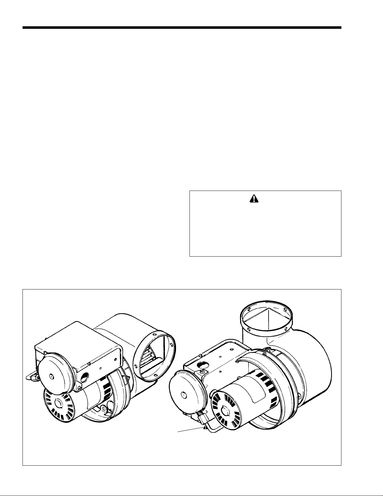
3. To prevent bearing wear, and for proper FanProver Switch operation, make sure the Power
Venter motor shaft is horizontal (see Fig. 1).
4. The ambient temperature surrounding the Power
Venter must not exceed 104°F (40°C).
5. The venting system must be sloped upwards not
less than 1/4 inch per foot from the boiler to the
vent terminal. The vent system must be installed
to prevent the collection of condensate where
necessary, and must be provided with a means of
drainage.
6. Condensate lines or single wall exhaust vent
shall not be run through an unheated space or
interior part of an open chimney unless the
exhaust vent is insulated.
7. The vent system must be adequately supported to
prevent sagging, but in no case shall the supports
be less than every 3 feet (0.9m).
8. Inlet and outlet piping must conform to Figure 4,
5 or 6.
9. Do not place any elbows within two feet of
venter outlet.
SECTION 2.
2a. Side Wall Vent Hood Location
If possible, locate the side wall vent hood on a
wall not normally subjected to high winds. This will
lessen the possibility of gas valve interruption during
periods when the winds are stronger than 40 MPH
(64 kmh). The Vent Hood location must comply with
the following specifications (see Fig. 2):
Caution
Flue gas temperature can exceed 150°F (66°C)
depending on the appliance being vented and the
length of the vent system. Do not terminate a side
wall vent system where vinyl siding has been
installed on the building exterior, since damage to
the vinyl siding may result.
Horizontal Discharge Vertical Discharge
Figure 1. Discharge Options.
Air Pressure
Sensing Tube
Page 5

Mighty Venter Power Vent System
Page 5
1. Locate the Vent Hood a minimum of 7 feet
(2.1m) above a public walkway .
2. Locate the Vent Hood a minimum of 3 feet
(0.9m) above, or 4 feet (1.2m) below and 4 feet
(1.2m) horizontally from any door, window, or
gravity air inlet into the building. The Vent Hood
cannot terminate less than 6 feet (1.8m) above
any forced air inlet located within 10 feet (3.0m).
3. The Vent Hood must be installed at least 3 feet
(0.9m) from any other building opening or any
gas service regulator.
4. Do not install the vent hood closer than 2 feet
(0.6m) from an adjacent building.
5. Install the Vent Hood no closer than 3 feet (0.9m)
from an inside corner of an L-shaped structure.
6. Do not terminate the Vent Hood directly above a
gas utility meter or service regulator.
CODE REQUIREMENTS
The Power Venter installation must be in
accordance with the following requirements of the
National Fuel Gas Code:
All portions of the vent system under positive
pressure during operation (on the outlet side of the
Power Venter) shall be designed and installed so as to
prevent leakage of flue or vent gases into a building.
The boiler must enter the vent system on the inlet
side of the Power Venter.
Provision shall be made to interlock the
boiler(s) to prevent the flow of gas to the main burners
when the draft system is not performing so as to
satisfy the operating requirements of the equipment for
safe performance. See the “Electrical Wiring” section
in this manual for details.
Power Venter Installation
The Power Venter must be mounted with the
motor shaft horizontal to ensure proper operation of
the Fan-Prover switch and prevent motor bearing
wear (see Fig. 1). The installer must supply plumber's
strap or threaded rod with nut and washers for
mounting.
Vent Hood
7 (2.1) Minimum
Above Public
Walkway
6 (1.8) Above Any
Outside Air Intake
Within 10 (3.0)
Vent Hood
4 (1.2)
Minimum
Vent Hood
Vent Hood Must Be
Mounted At Least
4 (1.2) Below Windows
1 (0.3) Above Grade
3 (0.9) Minimum
4 (1.2)
Minimum
Vent Hood
Vent Hood Must Be
**
Mounted At Least
3 (0.9) Above Windows
and Doors
4 (1.2)
Minimum
Figure 2. Side Wall Vent Hood Locations.
Dimensions shown in feet (m).
Page 6

Page 6
LAARS Heating Systems
To facilitate installation and reduce vibration, 2
mounting brackets, 2 rubber isolators, and 2 rubber
grommets are included. One of the brackets can be
used as a temporary “third hand” while positioning it
for permanent installation (see Figure 3).
When installing the Power Venter for horizontal
discharge, install one of the brackets to the electrical
box using the nut/screw provided. Install the other to
the damper rod. When installing the Power Venter for
vertical discharge, only one bracket is needed. Mount
this bracket to the motor as shown in Figure 3.
SECTION 3.
Electrical Wiring
WARNING
All wiring from the Power Venter to the appliance
must comply with local codes, or in their absence,
the National Electric Code (NFPA #70) in the United
States and/or CSA C22.1 Electrical Code in
Canada.
Disconnect 115 VAC power to the appliance before
proceeding with wiring the Power Venter. The power
can be disconnected by tripping the circuit breaker
or removing the fuse protecting the appliance.
All wiring must comply with applicable codes and
ordinances. All 115 VAC wiring must be rigid or
semi-rigid metal conduit with 18 AWG, 300 VAC,
90° C rated copper wire.
Boiler Vent Vent
Fig. Boiler Draft Hood Pipe Hood Rough-in
No. Size Outlet Dia. Dia. Dim.
4 175 6" 4" 4" 8.0" Dia.
5 250 7" 6" 6" 9.0" Dia.
6 325 8" 6" 6" 9.0" Dia.
6 400 9" 6" 6" 9.0" Dia.
Table 2.
Wire the hot water boiler and the Power Venter
exactly as shown in Figure 7 and follow these steps:
1. Connect the black and white (115 VAC) wires
from the Power Venter to the boiler control box as
shown in Figure 7.
2. Connect the red, blue and yellow (24 VAC)
wires to the terminal block as shown in Figure 7.
Make sure the current capacities of the wires,
switches, etc. at 115 VAC meet the ratings in Table 3.
3. Remove factory-installed jumper from
between boiler terminals 3 and 4.
Equivalent Full Load
Power Venter Currents
Model Motor HP (Amps - 115 VAC)
MV1 1/25 1.3
MV2 1/8 4.4
Table 3. Electrical Ratings.
Figure 3. Power Venter Discharge Options.
Page 7

Mighty Venter Power Vent System
7.6"
4"
Page 7
8.6"
6"
4" x 6"
Figure 4.
Size 175
MV1
6"
4" x 6"
4" x 6"
MV1
6" x 7"
Figure 5.
Size 250
8.6"
6" x 8" for 325
6" x 9" for 400
Sizes 325-400
MV2
Figure 6.
Page 8

Page 8
LAARS Heating Systems
3a. Safety Interlock Test
1. Turn the appliance thermostat/aquastat high
enough to call for heat.
2. Verify by fan rotation that the Power Venter
begins operating before the gas valve becomes
energized.
3. With the appliance firing and the Power Venter
operating, disrupt power to the Power Venter by
removing one of the black wires from the Power
Venter relay. Make sure the appliance gas valve
turns off.
WARNING
Do not operate the boiler that does not shut off when
the Power Venter is disabled.
3b. Maintenance
1. Oil the motor every six months with 2 drops of
S.A.E. #20 oil. The oil ports are located on top of
the motor.
2. Laars recommends that the boiler system be
checked annually by a qualified service
technician. The inspection should include
checking all vent pipe and connections for
blockage and leaks, and a safety interlock test.
Parts List
Part Number Description Boiler Size
10718702 Mighty Venter Kit (MV1) 175
D2008801 Power Venter
D0019700 Vent Hood, 7.6" Dia.
D0018800 4" x 6" Reducer (Qty. 1)
10718703 Mighty Venter Kit (MV1) 250
D2008801 Power Venter
D0019800 Vent Hood, 8.6" Dia.
D0018900 6" x 7" Reducer (Qty. 1)
D0018800 4" x 6" Reducer (Qty. 2)
10718704 Mighty Venter Kit (MV2) 325
D2008802 Power Venter
D0019800 Vent Hood, 8.6" Dia.
D0019000 6" x 8" Reducer (Qty. 1)
10718705 Mighty Venter Kit (MV2) 400
D2008802 Power Venter
D0019800 Vent Hood, 8.6" Dia.
D0019100 6" x 9" Reducer (Qty. 1)
Page 9

Mighty Venter Power Vent System
Mighty Therm Mighty Venter
Page 9
Junction Box
Mighty
Venter
Color Legend
BK - Black
BL - Blue
GR - Green
R - Red
W - White
Y - Yellow
Factory Wiring
24V
115V
Field Wiring
24 V
115V
Figure 7. Wiring Diagram For Mighty Therm, Model HH, PH, VW, PW, Sizes 175 through 400.
Page 10

Page 10
LAARS Heating Systems
Page 11

Mighty Venter Power Vent System
Page 11
Page 12

Laars Heating Systems
Mighty Venter
™ Power Vent System
Your Laars Mighty Venter Power Vent System is backed by this
warranty to assure your complete satisfaction.
Laars warrants the Mighty Venter; the motor, fan prover switch and sheet metal parts
to be free of defects in materials and workmanship for 18 months from date of
purchase or 12 months from date of installation, whichever comes first.
The above warranty applies only if the installation
and operating instructions applicable to the model
purchased are expressly and completely
followed.These instructions are furnished with the
unit and are also available by writing to the Laars
factory. The liability of Laars shall not exceed the
repair or replacement of defective parts by factory
authorized technicians, and shall not include
transportation to or from factory, any labor costs,
and consequential or incidental damages. Ship
inoperative parts or complete system with Serial
number, Model number and purchase date,
transportation prepaid, directly to address below,
attention Customer Service, for evaluation and
warranty consideration.
This warranty gives you specific legal rights. You may
also have other rights which vary from state to state,
and by province. Some states and provinces do not
allow the exclusion or limitation of incidental or
consequential damages, so the above limitation or
exclusion may not apply to you.
800.900.9276 • Fax 800.559.1583 (Customer Service, Service Advisors)
20 Industrial Way , Rochester , NH 03867 • 603.335.6300 • Fax 603.335.3355 (Applications Engineering)
1869 Sismet Road, Mississauga, Ontario, Canada L4W 1W8 • 905.238.0100 • Fax 905.366.0130
www.Laars.com Litho in U.S.A. © Laars Heating Systems 0907 Document 4126D
H0168800D
 Loading...