

Page 1

HD 18/50-4 Cage Classic
001
HD 18/50-4 Cage Advanced
Deutsch 3
English 14
Français 24
Italiano 35
Nederlands 46
Español 57
Português 68
Dansk 79
Norsk 89
Svenska 99
Suomi 109
Ελληνικά 119
Türkçe 131
Русский 142
Magyar 154
Čeština 165
Slovenščina 175
Polski 185
Româneşte 196
Slovenčina 207
Hrvatski 218
Srpski 228
Български 239
Eesti 251
Latviešu 261
Lietuviškai 272
Українська 282
59671520 09/19
Page 2
2
Page 3
Lesen Sie vor der ersten Benut-
zung Ihres Gerätes diese Originalbetriebsanleitung, handeln Sie danach
und bewahren Sie diese für späteren Gebrauch oder für Nachbesitzer auf.
– Vor erster Inbetriebnahme Sicherheits-
hinweise Nr. 5.963-314.0 unbedingt lesen!
– Bei Transportschaden sofort Händler
informieren.
– Prüfen Sie beim Auspacken den Pa-
ckungsinhalt auf fehlendes Zubehör
oder Beschädigungen.
Inhaltsverzeichnis
Umweltschutz . . . . . . . . . . . . . DE 1
Übersicht. . . . . . . . . . . . . . . . . DE 1
Bestimmungsgemäße Verwen-
dung . . . . . . . . . . . . . . . . . . . . DE 2
Symbole auf dem Gerät . . . . . DE 2
Sicherheitshinweise . . . . . . . . DE 2
Sicherheitseinrichtungen. . . . . DE 3
Inbetriebnahme. . . . . . . . . . . . DE 4
Bedienung. . . . . . . . . . . . . . . . DE 5
Transport. . . . . . . . . . . . . . . . . DE 7
Lagerung des Gerätes . . . . . . DE 8
Pflege und Wartung . . . . . . . . DE 8
Hilfe bei Störungen . . . . . . . . . DE 8
Garantie . . . . . . . . . . . . . . . . . DE 9
Allgemeine Hinweise. . . . . . . . DE 9
EU-Konformitätserklärung. . . . DE 10
Technische Daten . . . . . . . . . . DE 11
Umweltschutz
Die Verpackungsmaterialien sind
recyclebar. Bitte werfen Sie die
Verpackungen nicht in den Hausmüll, sondern führen Sie diese einer Wiederverwertung zu.
Altgeräte enthalten wertvolle recyclingfähige Materialien, die einer Verwertung zugeführt werden
sollten. Batterien, Öl und ähnliche
Stoffe dürfen nicht in die Umwelt
gelangen. Bitte entsorgen Sie Altgeräte deshalb über geeignete
Sammelsysteme.
Bitte Motorenöl, Heizöl, Diesel und Benzin
nicht in die Umwelt gelangen lassen. Bitte
Boden schützen und Altöl umweltgerecht
entsorgen.
Hinweise zu Inhaltsstoffen (REACH)
Aktuelle Informationen zu Inhaltsstoffen finden Sie unter:
www.kaercher.de/REACH
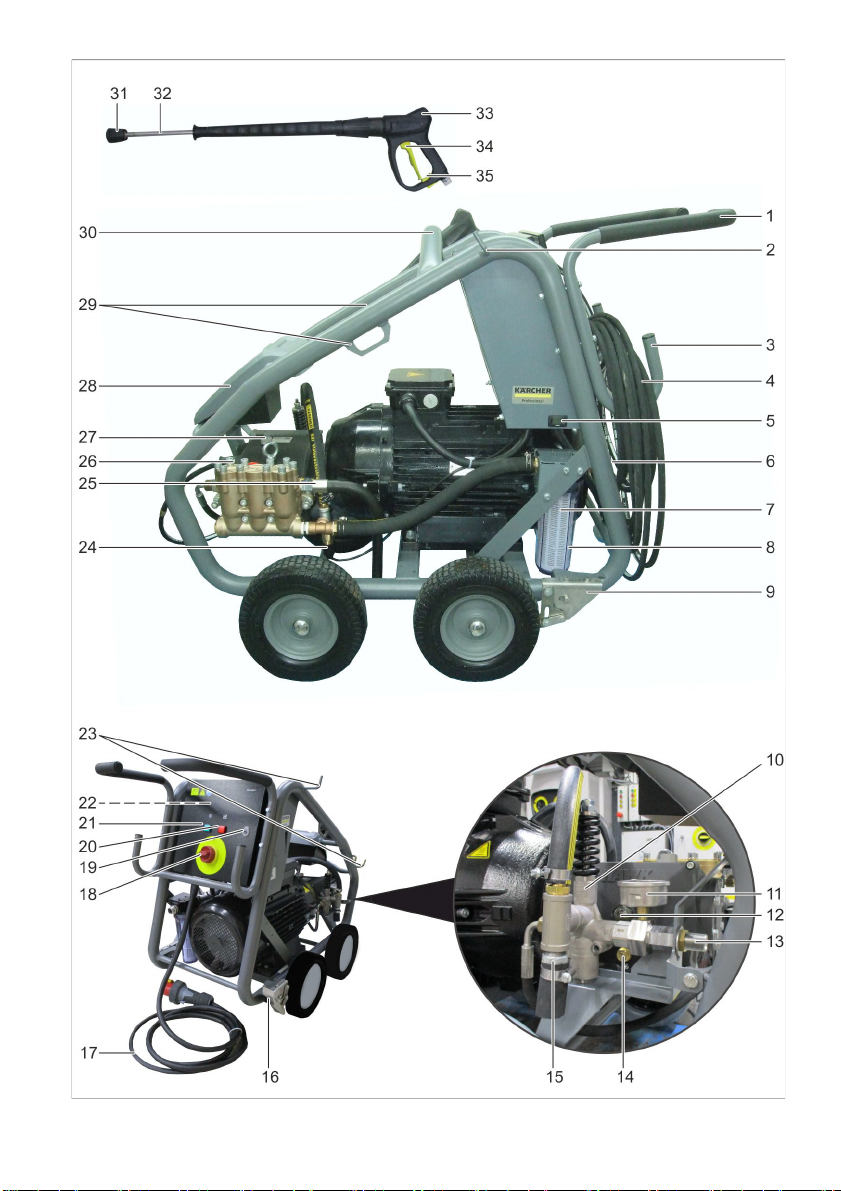
Übersicht
Abbildungen siehe Seite 2
1 Schubbügel
2 Schlauchhalter
3 Schlauch-/Kabelhalter
4 Hochdruckschlauch
5 Betriebsstundenzähler
6 Wasseranschluss
7Filter
8 Filtergehäuse
9 Feststellbremse
10 Classic: Überströmventil
Advanced: Überströmventil mit Druck-
entlastung
11 Manometer
12 Ölstandsanzeige
13 Hochdruckanschluss
14 Ölablassschraube
15 Thermoventil
16 Betätigungshebel Feststellbremse
17 Netzanschlusskabel mit Stecker
(60 Hz-Ausführung ohne Stecker)
18 Geräteschalter
19 Schloss
20 Kontrollleuchte Wassermangel
21 Kontrollleuchte Betriebszustand
22 Motorschutzschalter
23 Strahlrohrablage
24 Wassermangelsicherung
25 Sicherheitsventil
26 Hochdruckanschluss
27 Öleinfüllstutzen
28 Zubehörfach
29 Verzurrösen
30 Strebe für Kranverladung
31 Powerdüse mit Überwurfmutter
32 Strahlrohr
33 Handspritzpistole
34 Hebel Handspritzpistole
35 Sicherungsraste
– 1
3DE
Page 4
Farbkennzeichnung
– Bedienelemente für den Reinigungs-
prozess sind gelb.
– Bedienelemente für die Wartung und
den Service sind hellgrau.
Bestimmungsgemäße
Verwendung
Verwenden Sie diesen Hochdruckreiniger
ausschließlich:
– zum Reinigen von Maschinen, Fahr-
zeugen, Bauwerken, Werkzeugen.
– mit von Kärcher zugelassenem Zube-
hör und Ersatzteilen.
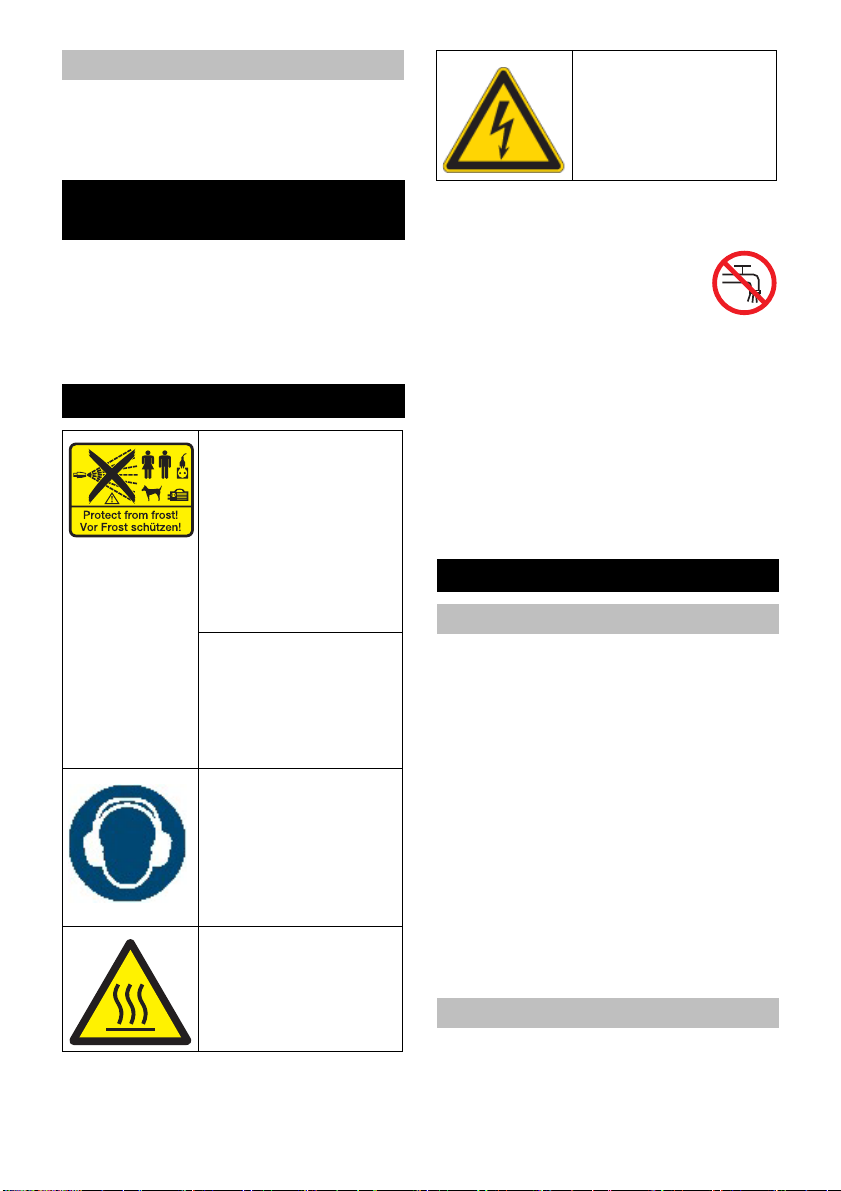
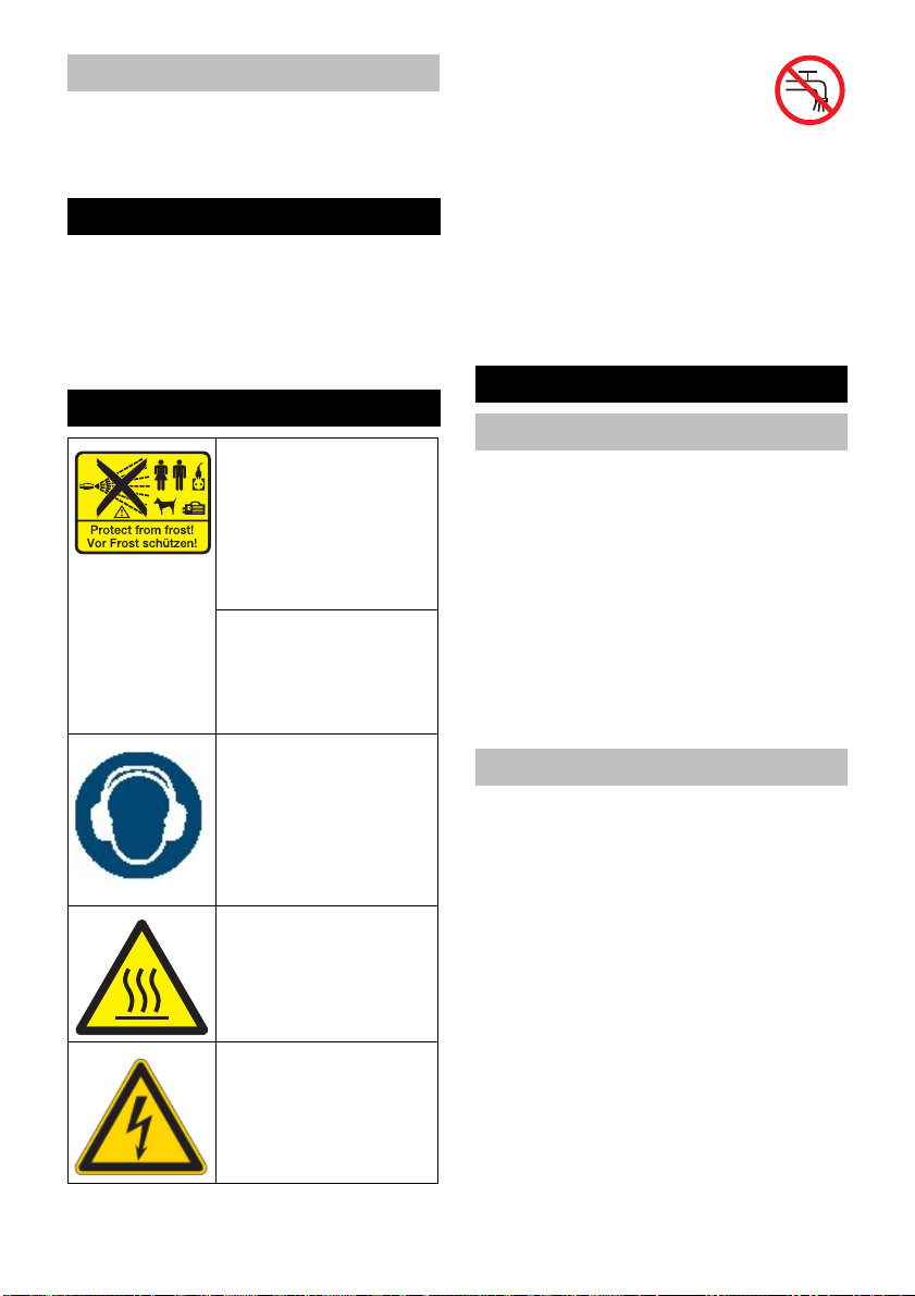
Symbole auf dem Gerät
Hochdruckstrahlen können bei unsachgemäßem Gebrauch gefährlich sein. Der Strahl darf
nicht auf Personen, Tiere, aktive elektrische
Ausrüstung oder auf das
Gerät selbst gerichtet
werden.
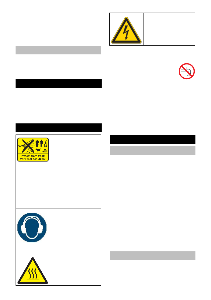
Beschädigungsgefahr
durch gefrierendes Wasser! Gerät im Winter in einem beheizten Raum
aufbewahren oder entleeren.
Gefahr von Gehörschäden. Bei der Arbeit mit
dem Gerät unbedingt einen geeigneten Gehörschutz tragen.
Verletzungsgefahr!
Schutzbrille tragen.
Verbrennungsgefahr
durch heiße Oberflächen!
Warnung vor gefährlicher
elektrischer Spannung!
몇 WARNUNG
Vorschriften des Wasserversorgungsunternehmens beachten.
Gemäß gültiger Vorschriften darf
das Gerät nie ohne Systemtrenner
am Trinkwassernetz betrieben
werden. Es ist ein geeigneter Systemtrenner der Fa. KÄRCHER oder alternativ ein Systemtrenner gemäß EN 12729
Typ BA zu verwenden.
Wasser, das durch einen Systemtrenner
geflossen ist, wird als nicht trinkbar eingestuft.
몇 VORSICHT
Systemtrenner immer an der Wasserversorgung, niemals direkt am Gerät anschließen.
Sicherheitshinweise
Gefahrenstufen
GEFAHR
Hinweis auf eine unmittelbar drohende Gefahr, die zu schweren Körperverletzungen
oder zum Tod führt.
몇 WARNUNG
Hinweis auf eine möglicherweise gefährliche Situation, die zu schweren Körperverletzungen oder zum Tod führen kann.
몇 VORSICHT
Hinweis auf eine möglicherweise gefährliche Situation, die zu leichten Verletzungen
führen kann.
ACHTUNG
Hinweis auf eine möglicherweise gefährliche Situation, die zu Sachschäden führen
kann.
Hochdruckschlauch
GEFAHR
Verletzungsgefahr!
– Nur Original-Hochdruckschläuche ver-
wenden.
4 DE
– 2
Page 5

– Der Hochdruckschlauch und die Spritz-
einrichtung müssen für den in den
Technischen Daten angegebenen maximalen Betriebsüberdruck geeignet
sein.
– Kontakt mit Chemikalien vermeiden.
– Hochdruckschlauch täglich kontrollie-
ren.
Geknickte Schläuche nicht mehr verwenden.
Ist die äußere Drahtlage sichtbar,
Hochdruckschlauch nicht mehr verwenden.
– Hochdruckschlauch mit beschädigtem
Gewinde nicht mehr verwenden.
– Hochdruckschlauch so verlegen, dass
dieser nicht überfahren werden kann.
– Durch Überfahren, Knicken, Stoßen be-
lasteten Schlauch nicht mehr verwenden, auch wenn keine Beschädigung
sichtbar ist.
– Hochdruckschlauch so lagern, dass
keine mechanischen Belastungen auftreten.
– Maximales Anzugsdrehmoment der
Anschlußverschraubungen des Hochdruckschlauchs 20 Nm.
Sicherheitseinrichtungen
Sicherheitseinrichtungen dienen dem
Schutz des Benutzers und dürfen nicht außer Betrieb gesetzt oder in ihrer Funktion
umgangen werden.
Geräteschalter
Dieser verhindert das unbeabsichtigte Anlaufen des Gerätes. Bei Arbeitspausen
oder beim Beenden des Betriebs ausschalten.
Sicherungsraste
Die Sicherungsraste an der Handspritzpistole verhindert unbeabsichtigtes Auslösen
der Handspritzpistole.
Überströmventil
– nur bei Classic-Variante
– Wird die Handspritzpistole geschlos-
sen, öffnet das Überströmventil und die
komplette Wassermenge fließt zur
Pumpensaugseite zurück.
Überströmventil ist werkseitig eingestellt
und plombiert. Einstellung nur durch den
Kundendienst.
Überströmventil mit
Druckentlastung
– nur bei Advanced-Variante
– Wird die Handspritzpistole geschlos-
sen, öffnet das Überströmventil und die
komplette Wassermenge fließt zur
Pumpensaugseite zurück.
– Wird die Handspritzpistole geschlos-
sen, wird der Wasserdruck im Hoch-
druckschlauch abgesenkt. Dadurch
sinkt die Betätigungskraft der
Handspritzpistole und die Lebensdauer
des Gerätes erhöht sich.
Überströmventil ist werkseitig eingestellt
und plombiert. Einstellung nur durch den
Kundendienst.
Sicherheitsventil
Das Sicherheitsventil öffnet, wenn das
Überströmventil defekt ist.
Das Sicherheitsventil ist werkseitig eingestellt und plombiert. Einstellung nur durch
den Kundendienst.
Wassermangelsicherung
Die Wassermangelsicherung schaltet den
Motor bei unzureichender Wasserversorgung (Wasserdruck zu niedrig) ab.
Die Kontrollleuchte Wassermangel leuchtet.
Thermoventil
Das Thermoventil schützt die Hochdruckpumpe gegen unzulässige Erwärmung im
Kreislaufbetrieb bei geschlossener
Handspritzpistole.
Das Thermoventil öffnet bei Überschreitung der maximal zulässigen Wassertemperatur von 80 °C und leitet das Heißwasser ins Freie.
Motorschutzschalter
Der Motorschutzschalter unterbricht den
Stromkreis, wenn der Motor überlastet ist.
– 3
5DE
Page 6
Inbetriebnahme
GEFAHR
Verletzungsgefahr! Gerät, Zuleitungen,
Hochdruckschlauch und Anschlüsse müssen in einwandfreiem Zustand sein. Falls
der Zustand nicht einwandfrei ist, darf das
Gerät nicht benutzt werden.
Ölstand kontrollieren
Transportschraube durch mitgelieferte
Entlüftungsschraube ersetzen.
Ölstand der Hochdruckpumpe kontrol-
lieren.
Der Ölspiegel muss in der Mitte der Ölstandsanzeige sein.
Bei Bedarf Öl nachfüllen (siehe Techni-
sche Daten).
Zubehör montieren
몇 WARNUNG
Verletzungsgefahr durch ungeeignetes Zubehör. Nur Zubehör verwenden, das für
den Arbeitsdruck des Gerätes (siehe
„Technische Daten“) zugelassen ist.
Zubehör nur bei ausgeschaltetem Gerät
montieren.
Maximales Anzugsdrehmoment der Anschlußverschraubungen des Hochdruckschlauchs 20 Nm.
Hochdruckschlauch und Strahlrohr mit
der Handspritzpistole verbinden.
Powerdüse auf das Strahlrohr montie-
ren. Überwurfmutter handfest anziehen.
Hochdruckschlauch am Hochdruckan-
schluss des Gerätes montieren.
Stromversorgung
– Anschlusswerte siehe Technische Da-
ten.
– Der elektrische Anschluss muss von ei-
nem Elektroinstallateur ausgeführt werden und IEC 60364-1 entsprechen.
몇 WARNUNG
Die maximal zulässige Netzimpedanz am
elektrischen Anschlusspunkt (siehe Technische Daten) darf nicht überschritten werden.
Bei Unklarheiten bezüglich der an Ihrem
Anschlusspunkt vorliegenden Netzimpedanz setzen Sie sich bitte mit Ihrem Energieversorgungsunternehmen in Verbindung.
GEFAHR
– Prüfen, ob die Spannungsangabe auf
dem Typenschild mit der Spannung der
Stromquelle übereinstimmt.
– Ungeeignete elektrische Verlänge-
rungsleitungen können gefährlich sein.
Verwenden Sie im Freien nur dafür zu-
gelassene und entsprechend gekenn-
zeichnete elektrische Verlängerungslei-
tungen mit ausreichendem Leitungs-
querschnitt:
1 - 10 m: 10 mm
10 - 30 m: 16mm
2
2
60 Hz-Ausführung
Bei dieser Geräte-Ausführung muss der
passende Netzstecker durch eine Elektrofachkraft an der Netzanschlussleitung angebracht werden.
Wasseranschluss
몇 WARNUNG
Vorschriften des Wasserversorgungsunternehmens beachten.
Gemäß gültiger Vorschriften darf
das Gerät nie ohne Systemtrenner
am Trinkwassernetz betrieben
werden. Es ist ein geeigneter Systemtrenner der Fa. KÄRCHER oder alternativ ein Systemtrenner gemäß EN 12729
Typ BA zu verwenden.
Wasser, das durch einen Systemtrenner
geflossen ist, wird als nicht trinkbar eingestuft.
몇 VORSICHT
Systemtrenner immer an der Wasserversorgung, niemals direkt am Gerät anschließen.
Anschlusswerte siehe Technische Daten.
Zulaufschlauch (Mindestlänge 7,5 m,
Mindestdurchmesser 1“) am Wasser-
6 DE
– 4
Page 7

anschluss des Gerätes und am Wasserzulauf (zum Beispiel Wasserhahn)
anschließen.
Der Zulaufschlauch ist nicht im Lieferumfang enthalten.
Wasserzulauf öffnen.
Grenzwerte für die Wasserversorgung
ACHTUNG
Verschmutztes Wasser
Vorzeitiger Verschleiß oder Ablagerungen
im Gerät.
Versorgen Sie das Gerät nur mit sauberem
Wasser oder Recyclingwasser, das die
Grenzwerte nicht überschreitet.
Für die Wasserversorgung gelten folgende
Grenzwerte:
– Vorgeschalteter Wasserfilter: ≤10 µm
– Festkörpergehalt: maximal 50 mg/l
– Gesamthärte: 3-15° dH, 30-150 mg/l
CaO, 54-268 mg/l CaCO
3
– Kalziumhärte: 0,89-2,14 mmol/l
– pH-Wert: 6,5-9,5
– Basenkapazität pH 8,2: 0-0,25 mmol/l
– Gelöste Stoffe gesamt: 10-75 mg/l
– Elektrische Leitfähigkeit: 100-450 µS/
cm
– Chloride, z.B. NaCl: <100 mg/l
– Eisen, Fe: <0,2 mg/i
– Fluorid, F: <1,5 mg/l
– Freies Chlor, Cl: <1 mg/l
– Kupfer, Cu: <2 mg/l
– Mangan, Mn: <0,05 mg/l
– Phospat, H
– Silikate, Si
3PO4
: <10 mg/l
xOy
: <50 mg/l
– Sulfat, SO4: <100 mg/l
Filter reinigen
Wasserzulauf schließen.
Filtergehäuse abschrauben.
Filter herausziehen und reinigen.
Gerät entlüften.
Hinweis:
Das Gerät wird mit einem 80µm-Filter ausgeliefert.
Bei Benutzung der Rotordüse sollte ein
50µm-Filter (6.414-063.0) verwendet werden.
Wasser aus Behälter ansaugen
Zum Ansaugen von Wasser muss dem Gerät eine Vordruckpumpe vorgeschaltet werden.
Saugschlauch mit Wasser füllen.
Vordruckpumpe: 2.637-017.0
GEFAHR
Saugen Sie niemals Wasser aus einem
Trinkwasserbehälter an.
GEFAHR
Niemals lösungsmittelhaltige Flüssigkeiten
oder unverdünnte Säuren und Lösungsmittel ansaugen! Dazu zählen z.B. Benzin,
Farbverdünner oder Heizöl. Der Sprühnebel ist hochentzündlich, explosiv und giftig.
Kein Aceton, unverdünnte Säuren und Lösungsmittel verwenden, da sie die am Gerät verwendeten Materialien angreifen.
Gerät vor dem Betrieb entlüften.
Gerät entlüften
Wasserzulauf öffnen.
Düse abschrauben.
Hebel der Handspritzpistole betätigen.
Gerät einschalten und so lange laufen
lassen, bis das Wasser blasenfrei am
Strahlrohr austritt.
Gerät ausschalten und Düse wieder
aufschrauben.
Bedienung
GEFAHR
– Der Betrieb in explosionsgefährdeten
Bereichen ist untersagt.
– Gerät auf einen festen, ebenen Unter-
grund stellen.
– Der Hochdruckreiniger darf nicht von
Kindern betrieben werden. (Gefahr von
Unfällen durch unsachgemäße Verwendung des Gerätes).
– Der aus der Hochdruckdüse austreten-
de Wasserstrahl verursacht einen
Rückstoß der Pistole. Ein abgewinkeltes Strahlrohr kann zusätzlich ein Drehmoment verursachen. Deshalb Strahlrohr und Pistole fest in den Händen halten.
– 5
7DE
Page 8
– Niemals Wasserstrahl auf Personen,
Tiere, das Gerät selbst oder elektrische
Bauteile richten.
Niemals Wasserstrahl auf Personen,
Tiere, das Gerät selbst oder elektrische
Bauteile richten.
– Verletzungsgefahr durch Hochdruck-
strahl und aufgewirbelten Schmutz.
Schutzbrille, Schutzhandschuhe,
Schutzanzug, Spezial-Sicherheitsstie-
fel mit Mittelfußschutz tragen.
– Den Strahl nicht auf sich selbst oder an-
dere richten, um Kleidung oder Schuh-
werk zu reinigen.
Das Gerät nicht verwenden, wenn sich
–
andere Personen in Reichweite befinden.
– Gefahr von Gehörschäden. Bei der Ar-
beit mit dem Gerät unbedingt einen ge-
eigneten Gehörschutz tragen.
– Fahrzeugreifen/Reifenventile dürfen
wegen des hohen Wasserdrucks mit
diesem Gerät nicht gereinigt werden.
– Asbesthaltige und andere Materialien,
die gesundheitsgefährdende Stoffe ent-
halten, dürfen nicht gereinigt werden.
– Stets auf feste Verschraubung aller An-
schlussschläuche achten.
– Der Hebel der Handspritzpistole darf
bei Betrieb nicht festgeklemmt werden.
Netzanschlusskabel und Hochdruck-
–
schlauch dürfen nicht überfahren werden.
– Nur bei ausreichender Beleuchtung ar-
beiten.
Gerät einschalten
Wasserzulauf öffnen.
Netzstecker einstecken.
Geräteschalter auf „I“ stellen.
Sicherungsraste an der Handspritzpis-
tole durch Drücken entriegeln.
Hebel der Handspritzpistole betätigen.
Betrieb mit Hochdruck
몇 WARNUNG
Durch den austretenden Wasserstrahl an der
Hochdruckdüse wirkt eine Rückstoßkraft auf
die Handspritzpistole. Für sicheren Stand sorgen und Handspritzpistole und Strahlrohr mit
beiden Händen festhalten.
Die Schulterstütze (2.639-251.0) sollte zur
Vermeidung von Verletzungen und als Arbeitserleichterung bei Rückstößen >150N
verwendet werden.
Powerdüse
Das Gerät ist mit folgender Düse ausgestattet:
– Powerdüse, 15° Strahlwinkel
Hochdruck Flachstrahl (15°) für großflächige Verschmutzungen.
Der Arbeitsdruck kann am Manometer
abgelesen werden.
Hinweis:
Hochdruckstrahl immer zuerst aus größerer Entfernung auf zu reinigendes Objekt
richten, um Schäden durch zu hohen Druck
zu vermeiden.
Betrieb unterbrechen
Hebel der Handspritzpistole loslassen.
Hebel der Handspritzpistole mit Siche-
rungsraste sichern.
Handspritzpistole inkl. Strahlrohr in der
Strahlrohrablage ablegen.
Arbeitsdruck ändern
Der Arbeitsdruck kann durch Verwendung
unterschiedlicher Hochdruckdüsen verändert werden.
Druck
MPa (bar)
Flachstrahldüsen
50 (500) 15060 5.765-263.0
35 (350) 15075 2.113-073.0
25 (250) 15095 2.113-075.0
15 (150) 15120 2.113-077.0
Punktstrahldüsen
50 (500) 060 5.765-264.0
35 (350) 075 2.113-074.0
25 (250) 095 2.113-076.0
15 (150) 120 2.113-078.0
Düse aus oben stehender Tabelle wäh-
len.
Überwurfmutter vom Strahlrohr ab-
schrauben.
Düsengröße
Bestellnummer
8 DE
– 6
Page 9

Düse austauschen.
Überwurfmutter aufschrauben und fest-
ziehen.
Hinweis:
Bei dieser Methode der Druckverstellung
steht immer die volle Fördermenge von
1800 l/h zur Verfügung.
Betrieb beenden
Hebel der Handspritzpistole loslassen.
Geräteschalter auf „0“ stellen.
Wasserzulauf schließen.
Handspritzpistole betätigen, bis Gerät
drucklos ist.
Hebel der Handspritzpistole mit Siche-
rungsraste sichern.
Wasserzulaufschlauch vom Gerät ab-
schrauben.
Netzstecker ziehen.
Netzanschlusskabel, Hochdruck-
schlauch und Zubehör am Gerät ver-
stauen.
Frostschutz
몇 WARNUNG
Beschädigungsgefahr! Gefrierendes Wasser im Gerät kann Teile des Gerätes zerstören.
Gerät im Winter in einem beheizten Raum
aufbewahren oder entleeren. Bei längeren
Betriebspausen empfiehlt es sich, Frostschutzmittel durch das Gerät zu pumpen.
Wasser ablassen
Wasserzulaufschlauch und Hochdruck-
schlauch abschrauben.
Gerät mit Druckluft ausblasen.
Gerät mit Frostschutzmittel durchspülen
Hinweis:
Handhabungsvorschriften des Frostschutzmittelherstellers beachten.
Handelsübliches Frostschutzmittel
durch das Gerät pumpen.
Dadurch wird auch ein gewisser Korrosionsschutz erreicht.
Transport
몇 VORSICHT
Verletzungs- und Beschädigungsgefahr!
Gewicht des Gerätes beim Transport beachten.
Fahren
Betätigungshebel Feststellbremse
nach hinten ziehen.
Abstellen
Betätigungshebel Festellbremse nach
vorne drücken.
Krantransport
Hebeeinrichtung in der Mitte der Strebe
für Kranverladung befestigen.
Sicherheitshinweise zur Verkranung
GEFAHR
Verletzungsgefahr durch herunterfallendes
Gerät.
– Die örtlichen Unfallverhütungsvorschrif-
ten und Sicherheitshinweise beachten.
– Vor jedem Krantransport Vorrichtung
für Kranverladung auf Beschädigung
kontrollieren.
– Vor jedem Krantransport Hebezeug auf
Beschädigung kontrollieren.
– Gerät nur an dieser Vorrichtung für
Kranverladung anheben.
– Keine Anschlagketten verwenden.
– Hebeeinrichtung vor unbeabsichtigtem
Aushängen der Last sichern.
– Strahlrohr mit Handspritzpistole und
lose Gegenstände vor dem Krantransport entfernen.
Während des Hebevorgangs keine Ge-
–
genstände auf dem Gerät transportieren.
– Das Gerät darf nur durch Personen mit
dem Kran transportiert werden, die in
der Bedienung des Krans unterwiesen
sind.
– Nicht unter die Last stehen.
– Darauf achten, dass sich im Gefahren-
bereich des Krans keine Personen aufhalten.
– Gerät nicht unbeaufsichtigt am Kran
hängen lassen.
– 7
9DE
Page 10

Sicherheitsüberprüfung
Sämtliche Schraubverbindungen der
Vorrichtung auf festen Sitz überprüfen
und gegebenenfalls nachziehen.
Staplertransport
Beim Staplertransport das Gerät mithilfe
der Verzurrösen nach den jeweils gültigen
Richtlinien gegen Herabfallen sichern.
Transport in Fahrzeugen
Beim Transport in Fahrzeugen das Gerät
mithilfe der Verzurrösen nach den jeweils
gültigen Richtlinien gegen Rutschen und
Kippen sichern.
Lagerung des Gerätes
몇 VORSICHT
Verletzungs- und Beschädigungsgefahr! Gewicht des Gerätes bei Lagerung beachten.
Dieses Gerät darf nur in Innenräumen gelagert werden.
Pflege und Wartung
GEFAHR
Verletzungsgefahr! Vor allen Pflege- und
Wartungsarbeiten, Gerät ausschalten und
Netzstecker ziehen.
Wartung
Sicherheitsinspektion/Wartungsvertrag
Mit Ihrem Händler können Sie eine regelmäßige Sicherheitsinspektion vereinbaren
oder einen Wartungsvertrag abschließen.
Bitte lassen Sie sich beraten.
Vor jedem Betrieb
Netzanschlusskabel prüfen.
Das Netzanschlusskabel darf nicht be-
schädigt sein (Gefahr durch elektri-
schen Schlag). Ein beschädigtes
Netzanschlusskabel muss unverzüglich
durch den autorisierten Kundendienst
oder eine Elektrofachkraft ausge-
tauscht werden.
Hochdruckschlauch auf Beschädigung
überprüfen (Berstgefahr).
Beschädigten Hochdruckschlauch un-
verzüglich austauschen.
10 DE
Ölstand an der Ölstandsanzeige der
Hochdruckpumpe kontrollieren.
Ist das Öl milchig (Wasser im Öl), sofort
Kundendienst aufsuchen.
Gerät (Pumpe) auf Dichtheit prüfen.
3 Tropfen Wasser pro Minute sind zulässig und können an der Geräteunterseite austreten. Bei stärkerer
Undichtigkeit Kundendienst aufsuchen.
Wöchentlich
Filtereinsatz reinigen.
Nach den ersten 50 Betriebsstunden
Öl der Hochdruckpumpe wechseln.
Jährlich oder nach 500 Betriebsstunden
Öl der Hochdruckpumpe wechseln.
Ölsorte und Füllmenge siehe „Techni-
sche Daten“.
Ölablassschraube herausdrehen.
Öl in Auffangbehälter ablassen.
Ölablassschraube einschrauben.
Neues Öl langsam bis zur Mitte der Öl-
standsanzeige einfüllen.
Hinweis:
Luftblasen müssen entweichen können.
Hilfe bei Störungen
Kleinere Störungen können Sie mit Hilfe
der folgenden Übersicht selbst beheben.
Im Zweifelsfall wenden Sie sich bitte an den
autorisierten Kundendienst.
GEFAHR
Verletzungsgefahr! Vor allen Pflege- und
Wartungsarbeiten, Gerät ausschalten und
Netzstecker ziehen.
WARNUNG
Reparaturarbeiten und Arbeiten an elektrischen Bauteilen dürfen nur vom autorisierten Kundendienst durchgeführt werden.
Kontrollleuchte
Die Kontrollleuchte zeigt Betriebszustände
(grün) und Störungen (rot) an.
Rücksetzen:
Geräteschalter auf „0“ stellen.
Kurz warten.
Geräteschalter auf „I“ stellen.
– 8
Page 11

Betriebszustandsanzeige
Dauerlicht grün:
– Gerät ist betriebsbereit.
Störungsanzeige
Dauerlicht rot:
– Wassermangel
Gerät läuft nicht
– Keine Netzspannung
Prüfen, ob die angegebene Spannung
auf dem Typenschild mit der Spannung
der Stromquelle übereinstimmt.
Netzanschlusskabel auf Beschädigung
prüfen.
– Wassermangelsicherung hat wegen zu
geringem Wasserzulaufdruck ange-
sprochen.
Die Kontrollleuchte Wassermangel
leuchtet.
Wasserzulaufdruck prüfen, Minimal-
wert siehe „Technische Daten“.
Zur Wiederinbetriebnahme den Geräte-
schalter auf Stellung „0“ stellen, dann
wieder einschalten.
– Motor überlastet/überhitzt bzw. Motor-
schutzschalter hat ausgelöst.
Gerät ausschalten und abkühlen las-
sen. Ursache der Störung beseitigen.
Gerät wieder einschalten.
Gerät baut keinen Druck auf
– Falsche Düse
Düse auf richtige Größe überprüfen
(siehe „Technische Daten“).
– Düse ausgespült.
Düse reinigen/erneuern.
– Filter verschmutzt.
Filter am Wasseranschluss reinigen.
Filtergehäuse aufschrauben, Filter ent-
nehmen, reinigen und wieder einset-
zen.
– Luft im System
Gerät entlüften.
Düse abschrauben. Gerät einschalten
und so lange laufen lassen, bis das
Wasser blasenfrei am Strahlrohr aus-
tritt. Gerät ausschalten und Düse wie-
der aufschrauben.
– Zulaufleitungen zur Pumpe undicht
oder verstopft
Sämtliche Zulaufleitungen zur Pumpe
auf Dichtheit oder Verstopfung prüfen.
Hochdruckpumpe undicht
3 Tropfen Wasser pro Minute sind zu-
lässig und können an der Geräteunterseite austreten. Bei stärkerer Undichtigkeit Kundendienst aufsuchen.
Hochdruckpumpe klopft
Sämtliche Zulaufleitungen zur Hoch-
druckpumpe auf Dichtheit oder Verstopfung überprüfen.
Gerät entlüften.
Düse abschrauben. Gerät einschalten
und so lange laufen lassen, bis das
Wasser blasenfrei am Strahlrohr austritt. Gerät ausschalten und Düse wieder aufschrauben.
Garantie
In jedem Land gelten die von unserer zuständigen Vertriebs-Gesellschaft herausgegebenen Garantiebedingungen. Etwaige
Störungen an dem Gerät beseitigen wir innerhalb der Garantiefrist kostenlos, sofern
ein Material- oder Herstellungsfehler die
Ursache sein sollte.
Die Garantie tritt nur dann in Kraft, wenn Ihr
Händler die beigefügte Antwortkarte beim
Verkauf vollständig ausfüllt, abstempelt
und unterschreibt und Sie die Antwortkarte
anschließend an die Vertriebs-Gesellschaft
Ihres Landes schicken.
Im Garantiefall wenden Sie sich bitte mit
Zubehör und Kaufbeleg an Ihren Händler
oder die nächste autorisierte Kundendienststelle.
Allgemeine Hinweise
Zubehör und Ersatzteile
몇 WARNUNG
Verletzungsgefahr durch ungeeignetes Zubehör. Nur Zubehör verwenden, das für
den Arbeitsdruck des Gerätes (siehe
„Technische Daten“) zugelassen ist.
– 9
11DE
Page 12

– Es dürfen nur Zubehör und Ersatzteile
Chairman of the Board of Management
Director Regulatory Affairs & Certification
verwendet werden, die vom Hersteller
freigegeben sind. Original-Zubehör und
Original-Ersatzteile bieten die Gewähr
dafür, dass das Gerät sicher und stö-
rungsfrei betrieben werden kann.
– Eine Auswahl der am häufigsten benö-
tigten Ersatzteile finden Sie am Ende
der Betriebsanleitung.
– Weitere Informationen über Ersatzteile
erhalten Sie unter www.kaercher.com
im Bereich Service.
EU-Konformitätserklärung
Hiermit erklären wir, dass die nachfolgend
bezeichnete Maschine aufgrund ihrer Konzipierung und Bauart sowie in der von uns
in Verkehr gebrachten Ausführung den einschlägigen grundlegenden Sicherheitsund Gesundheitsanforderungen der EURichtlinien entspricht. Bei einer nicht mit
uns abgestimmten Änderung der Maschine
verliert diese Erklärung ihre Gültigkeit.
Produkt: Hochdruckreiniger
Typ: 1.367-xxx
Einschlägige EU-Richtlinien
2006/42/EG (+2009/127/EG)
2014/30/EU
2000/14/EG
Dokumentationsbevollmächtigter:
S. Reiser
Alfred Kärcher SE & Co. KG
Alfred-Kärcher-Straße 28-40
71364 Winnenden (Germany)
Tel.: +49 7195 14-0
Fax: +49 7195 14-2212
Winnenden, 2019/08/01
Angewandte harmonisierte Normen
EN 55014–1: 2006+A1: 2009+A2: 2011
EN 55014–2: 2015
EN 61000–3–2: 2014
EN 61000–3–11: 2000
EN 62233: 2008
EN 1829-1
EN 1829-2
Angewandtes Konformitätsbewertungsverfahren
2000/14/EG 2000/14/EG: Anhang V
Schallleistungspegel dB(A)
HD 18/50-4 Cage
Gemessen: 98
Garantiert: 100
Die Unterzeichnenden handeln im Auftrag
und mit Vollmacht des Vorstands.
12 DE
– 10
Page 13

Technische Daten
Typ HD 18/50-4
Cage Clas-
sic EU
1.367-160.0
HD 18/50-4
Cage Clas-
sic KAP
1.367-161.0
HD 18/50-4
Cage Ad-
vanced
1.367-162.0
Stromanschluss
Spannung V 380 - 415
Stromart Hz 50 60 50
Anschlussleistung kW 36
Netzabsicherung (träge) A 63
Schutzart IPX5
Maximal zulässige Netzimpedanz Ohm 0,22
Wasseranschluss
Zulaufdruck (max.) MPa (bar) 1 (10)
Zulaufdruck (min.) bei max. Wasser-
MPa (bar) 0,05 (0,5)
menge
Zulauftemperatur, max. °C 60
Zulaufmenge, min. l/h (l/min) 2000 (33,3)
Zulaufschlauch-Länge (min.) m 7,5
Zulaufschlauch-Durchmesser (min.) Zoll 1
Leistungsdaten
Arbeitsdruck MPa (bar) 50 (500)
Max. Betriebsüberdruck (Sicherheits-
MPa (bar) 62 (620)
ventil)
Fördermenge, Wasser l/h (l/min) 1800 (30)
Düsengröße -- 15060
Rückstoßkraft der Handspritzpistole N 158
Betriebsstoffe
Ölmenge - Pumpe l 2,5
Ölsorte - Pumpe SAE 15W-40
Maße und Gewichte
Länge x Breite x Höhe mm 747 x 1317 x 1093
Typisches Betriebsgewicht kg 317
Ermittelte Werte gemäß EN 60335-2-79
Hand-Arm Vibrationswert
Rotordüse m/s
Flachstrahldüse m/s
Unsicherheit K m/s
Schalldruckpegel L
Unsicherheit K
pA
pA
Schallleistungspegel L
heit K
WA
+ Unsicher-
WA
dB(A) 82
dB(A) 3
dB(A) 101
2
2
2
9,4
1,4
2,1
– 11
13DE
Page 14
Please read and comply with
these original instructions prior
to the initial operation of your appliance and
store them for later use or subsequent owners.
– Before initial start-up it is definitely nec-
essary to read the safety information
no. 5.963-314.0!
– In case of transport damage inform ven-
dor immediately.
– When unpacking the product, make
sure that no accessories are missing
and that none of the package contents
have been damaged.
Contents
Environmental protection . . . . EN 1
Overview. . . . . . . . . . . . . . . . . EN 1
Proper use . . . . . . . . . . . . . . . EN 2
Symbols on the machine. . . . . EN 2
Safety instructions. . . . . . . . . . EN 2
Safety Devices . . . . . . . . . . . . EN 3
Start up . . . . . . . . . . . . . . . . . . EN 3
Operation . . . . . . . . . . . . . . . . EN 5
Transport. . . . . . . . . . . . . . . . . EN 7
Storing the device . . . . . . . . . . EN 7
Care and maintenance . . . . . . EN 7
Troubleshooting . . . . . . . . . . . EN 8
Warranty . . . . . . . . . . . . . . . . . EN 9
General information . . . . . . . . EN 9
EU Declaration of Conformity . EN 9
Technical specifications . . . . . EN 10
Environmental protection
The packaging material can be
recycled. Please do not throw
the packaging material into
household waste; please send it
for recycling.
Old appliances contain valuable
materials that can be recycled;
these should be sent for recycling. Batteries, oil, and similar
substances must not enter the
environment. Please dispose of
your old appliances using appropriate collection systems.
14 EN
Please do not release engine oil, fuel oil,
diesel and petrol into the environment Protect the ground and dispose of used oil in
an environmentally-clean manner.
Notes about the ingredients (REACH)
You will find current information about the
ingredients at:
www.kaercher.com/REACH
Overview
Illustrations on Page 2
1 Push handle
2 Hose holder
3 Hose/cable holder
4 High pressure hose
5 Operating hour counter
6 Water connection
7Filter
8Filter casing
9 Parking brake
10 Classic: Overflow valve
Advanced: Overflow valve with pres-
sure relief
11 Manometer
12 Oil level indicator
13 High pressure connection
14 Oil drain screw
15 Thermostat valve
16 Actuation lever for parking brake
17 Power cable with plug
(60 Hz model without plug)
18 Power switch
19 Lock
20 Indicator lamp low water
21 Control lamp operating state
22 Motor protection switch
23 Storage for spray pipe
24 Water shortage safeguard
25 Safety valve
26 High pressure connection
27 Oil filling nozzle
28 Accessory compartment
29 Transport eyelets
30 Strut for crane loading
31 Power nozzle with covering nut
32 Spray lance
33 Trigger gun
34 Lever for hand spray gun
35 Safety catch
– 1
Page 15
Colour coding
– The operating elements for the cleaning
process are yellow.
– The controls for the maintenance and
service are light gray.
Proper use
Use this high pressure cleaner exclusively
for:
– Cleaning machines, vehicles, buildings,
tools.
– with accessories and spare parts ap-
proved by Kärcher.
Symbols on the machine
High pressure jets can be
dangerous if improperly
used. The jet must not be
directed at persons, animals, live electrical
equipment or at the appliance itself.
Risk of damage from
freezing water! During
winter, store the device in
a heated room or empty
it.
Danger of hearing damage. Always wear suitable hearing protection
when working with the
device.
Risk of injury! Wear safety goggles.
Risk of burns on account
of hot surfaces!
Beware of dangerous
electrical current!
몇 WARNING
Observe regulations of water supplier.
According to applicable regulations, the appliance must never be
used on the drinking water net
without a system separator. A suitable system separator by KÄRCHER or alternatively a system separator according to
EN 12729 type BA must be used.
Water that was flowing through a system
separator is considered non-drinkable.
몇 CAUTION
Always connect the system separator to
the water supply, never directly to the appliance!
Safety instructions
Hazard levels
DANGER
Pointer to immediate danger, which leads
to severe injuries or death.
몇 WARNING
Pointer to a possibly dangerous situation,
which can lead to severe injuries or death.
몇 CAUTION
Pointer to a possibly dangerous situation,
which can lead to minor injuries.
ATTENTION
Pointer to a possibly dangerous situation,
which can lead to property damage.
High pressure hose
DANGER
Risk of injury!
– Only use original high-pressure hoses.
– The high-pressure hose and the injec-
tion system must be suitable for the
maximum operating pressure given in
the Technical Data.
– Avoid contact with chemicals.
– Check the high pressure hose daily.
Do not use hoses with kinks.
Stop using the high pressure hose if the
external wire layer is visible.
– Do not use the high-pressure hose any-
more if the winding is damaged.
– Lay the high-pressure hoses in such a
way that no vehicle can drive over it.
– Do not use high-pressure hoses that
have been driven over, kinked, pressed
– 2
15EN
Page 16

or bent even if there is no externally visible damage.
– Store the high-pressure hoses in such a
way that they are not subject to any mechanical load.
– Maximum tightening torque of the
screwed connections of the high-pressure hose; 20 Nm.
Safety Devices
Safety devices serve to protect the user
and must not be rendered in operational or
their functions bypassed.
Power switch
The switch prevents unintented starting of
the appliance. Stop the appliance during
breaks or after operation.
Safety catch
The safety catch on the handgun prevents
the handgun from being released unintentionally.
Overflow valve
– only for Classic variant
– If the hand spray gun is closed, the
overflow valve opens and the entire water volume will flow back to the pump
suction side.
Overflow valve is set and sealed by the
manufacturer. Setting only by customer
service.
Overflow valve with pressure relief
– only for Advanced variant
– If the hand spray gun is closed, the
overflow valve opens and the entire wa-
ter volume will flow back to the pump
suction side.
– If the trigger gun is closed, the water
pressure in the high-pressure hose is
reduced. This reduces the actuating
force of the trigger gun and increases
the service life of the device.
Overflow valve is set and sealed by the
manufacturer. Setting only by customer
service.
Safety valve
The safety valve opens when the overflow
valve is defective.
The safety valve is set by the manufacturer
and sealed. Setting only by customer service.
Water shortage safeguard
The lack of water fuse shuts off the engine
when the water supply is scarce (water
pressure too low).
The indicator lamp "lack of water" will illuminate.
Thermostat valve
The thermostat valve protects the highpressure pump from unacceptable heating
during circuit operation when the trigger
gun is closed.
The thermostat valve opens when the permissible water temperature of 80°C is exceeded and lets out the hot water into the
open.
Motor protection switch
The motor protection switch interrupts the
electric circuit if the motor is overloaded.
Start up
DANGER
Risk of injury! Device, supply lines, highpressure hose and connections must be in
faultless condition. If they are not in a perfect condition then the device must not be
used.
Check oil level
Replace the transport screw with the
supplied bleed screw.
Check oil level of the high pressure
pump.
The oil level must be at the centre of the
oil level display.
Add oil if required (see technical speci-
fications).
16 EN
– 3
Page 17

Attaching the Accessories
몇 WARNING
Risk of injury due to unsuitable accessories. Only use accessories that are approved for the working pressure of the device (see "Technical Data").
Only install accessories while the device is
switched off.
Maximum tightening torque of the screwed
connections of the high-pressure hose; 20 Nm.
Connect high pressure hose and spray
pipe to the hand spray gun.
Mount the power nozzle on the spray
pipe. Tighten covering nut firmly.
Connect the high pressure hose to the
high pressure connection point of the
machine.
Power supply
– For connection values refer to technical
specifications.
– The electrical connections must be
done by an electrician according to IEC
60364-1.
몇 WARNING
The highest allowed net impedance at the
electrical connection point (refer to technical data) is not to be exceeded.
In case of any uncertainty regarding the
present net impedance at your connection
point, please contact your local power supply company.
DANGER
– Check whether the voltage data on the
type plate corresponds with the voltage
of the power source.
– Unsuitable electrical extension cables
can be dangerous. Only use approved
and appropriately marked electrical ex-
tension cables with a sufficient line
cross section when outdoors:
1 - 10 m: 10 mm
10 - 30 m: 16mm
60 Hz model
With this appliance model, the matching
mains plug must be installed onto the
mains connecting line by an electrician.
2
2
Water connection
몇 WARNING
Observe regulations of water supplier.
According to applicable regulations, the appliance must never be
used on the drinking water net
without a system separator. A suitable system separator by KÄRCHER or alternatively a system separator according to
EN 12729 type BA must be used.
Water that was flowing through a system
separator is considered non-drinkable.
몇 CAUTION
Always connect the system separator to
the water supply, never directly to the appliance!
For connection values refer to technical
specifications.
Connect the supply hose (minimum
length 7.5 m, minimum diameter 1“) to
the water connection point of the appliance (such as the tap).
The supply hose is not included.
Open the water supply.
Water supply limit values
ATTENTION
Dirty water
Premature wear and tear or deposits in the
device.
Supply the device using only clean water,
or recycled water that does not exceed the
specified limit values.
The following limit values apply to the water
supply:
– Upstream water filter: ≤10 µm
– Solid body content: maximum 50 mg/l
– Total hardness: 3-15° dH, 30-150 mg/l
CaO, 54-268 mg/l CaCO
– Calcium hardness: 0.89-2.14 mmol/l
– pH value: 6.5-9.5
– Base capacity pH 8.2: 0-0.25 mmol/l
– Total dissolved substances: 10-75 mg/l
– Electrical conductivity: 100-450 µS/cm
– Chloride, e.g. NaCl: <100 mg/l
– Iron, Fe: <0.2 mg/l
3
– 4
17EN
Page 18

– Fluoride, F: <1.5 mg/l
– Free chlorine, Cl: <1 mg/l
– Copper, Cu: <2 mg/l
– Manganese, Mn: <0.05 mg/l
– Phosphate, H
– Silicate, Si
xOy
: <50 mg/l
3PO4
: <10 mg/l
– Sulphate, SO4: <100 mg/l
Cleaning the filter
Shut off water supply.
Unscrew the filter casing.
Pull out and clean the filter.
Vent appliance.
Note:
The device is supplied with an 80 μm filter.
A 50 μm filter (6.414-063.0) should be used
when the rotor nozzle is used.
Suck in water from vessel
A prepressure pump must be connected in
front of the appliance to suction water.
Fill the suction hose with water.
Advance pressure pump: 2.637-017.0
DANGER
Never suck in water from a drinking water
container.
DANGER
Never draw in fluids containing solvents or
undiluted acids and solvents! This includes
petrol, paint thinner and heating oil. The
spray mist is highly inflammable, explosive
and poisonous. Do not use acetone, undiluted acids and solvents, as they corrode
the materials used on the appliance.
Remove air from appliance before oper-
ation.
Deaerating the appliance
Open the water supply.
Unscrew the nozzle.
Press the lever on the hand spray gun.
Switch on the appliance and let it run
until the water exiting from the spray
pipe is bubble-free.
Switch off the appliance and fit the noz-
zle again.
Operation
DANGER
– The appliance may not be operated in
explosive atmospheres.
– Place the appliance on firm, even sur-
face.
– The high-pressure cleaner must not be
used by children. (Risk of accidents on
account of improper use of the device).
– The water jet coming out of the high-
pressure nozzle causes the gun to re-
coil. Further, an angular spray pipe can
cause additional torque. Hence, hold
the spray lance and gun firmly.
– Never direct the water jet on to persons,
animals, the appliance itself or electrical
components.
Never direct the water jet on to persons,
animals, the appliance itself or electrical
components.
– Risk of injury from high-pressure jet and
unsettled dirt. Wear safety goggles,
protective gloves, protective overalls
and special safety boots with foot pro-
tection.
– The jet must not be directed by the user
at him/herself or at other persons to
clean clothing or footwear.
– Do not use the device other persons are
within reach of it.
– Danger of hearing damage. Always
wear suitable hearing protection when
working with the device.
– Wheels/tyre valves must not be cleaned
with this device due to the high water
pressure.
– Do not clean materials containing as-
bestos or other health-hazardous sub-
stances.
– Pay attention to ensure that all screws
of all connecting hoses are tightened
properly.
– The lever of the trigger gun must not be
clamped tight during operation.
Do not drive over the main cable or the
–
high pressure hose.
– Only work with sufficient lighting.
18 EN
– 5
Page 19
Turning on the Appliance
Open the water supply.
Plug in the mains plug.
Set the appliance switch to "I".
Unlock the safety lock at the hand-
spray gun by pressing it.
Press the lever on the hand spray gun.
High pressure operation
몇 WARNING
The water jet that is emitted from the highpressure nozzle results in a repulsion power
acting on the hand spray gun. Make sure that
you have a firm footing and hold the trigger
gun and the spray lance with both hands.
The shoulder support (2.639-251.0) should
be used to prevent injuries and to make
work easier at recoil pressures > 150 N.
Power nozzle
The appliance is equipped with the following nozzles:
– Power nozzle, 15° spray angle
High pressure flat stream (15°) for large
areas of contamination.
The working pressure can be read from
the manometer.
Note:
Always direct the high-pressure jet at the
object to be cleaned from a distance to
avoid damage from high pressure.
Interrupting operation
Release the lever of the trigger gun.
Use the safety catch to secure the
handgun lever.
Store the hand spray gun and spray
pipe in the accessory mount.
Changing working pressure
The working pressure can be changed by
using different high-pressure nozzles.
Pressure
MPa (bar)
Flat jet nozzles
50 (500) 15060 5.765-263.0
35 (350) 15075 2.113-073.0
25 (250) 15095 2.113-075.0
Nozzle
size
Order number
15 (150) 15120 2.113-077.0
Detail nozzles
50 (500) 060 5.765-264.0
35 (350) 075 2.113-074.0
25 (250) 095 2.113-076.0
15 (150) 120 2.113-078.0
Select a nozzle from the table above.
Unscrew the union nut from the spray
lance.
Replace nozzle.
Screw on and tighten the union nut.
Note:
This method of pressure adjustment always means that the full flow rate of 1800 l/
h is always available.
Finish operation
Release the lever of the trigger gun.
Set the appliance switch to "0".
Shut off water supply.
Activate hand spray gun until device is
pressure less.
Use the safety catch to secure the
handgun lever.
Remove the water inlet hose from the
appliance.
Pull out the mains plug.
Stow away the mains cable, the high-
pressure hose and accessory at the ap-
pliance.
Frost protection
몇 WARNING
Risk of damage! Freezing water in the appliance can destroy parts of the appliance.
Store the appliance in a heated room during winter or empty it. During longer breaks
in operation, it is advisable to pump in antifrost agents into the appliance.
Drain water
Screw off water supply hose and high
pressure hose.
Blow through machine with com-
pressed air.
Flush device with anti-freeze agent
Note:
Observe handling instructions of the antifreeze agent manufacturer.
– 6
19EN
Page 20

Pump in conventional frost protection
agents through the appliance.
A certain corrosion protection is achieved
with this as well.
Transport
몇 CAUTION
Risk of personal injury or damage! Mind the
weight of the appliance during transport.
Driving
Pull the actuation lever of the parking
brake all the way to the back.
Stopping
Press the actuation lever of the parking
brake completely to the front.
Transport by crane
Connect the lifting device in the center
of the strut to load by crane.
Safety information about cranes
DANGER
Risk of injury due to machine dropping.
– Adhere to the local accident prevention
guidelines and safety notes.
Check the appliance for crane loading for
–
damage prior to each transport by crane.
– Check the lifting unit for damage prior to
each transport by crane.
– Only lift up the appliance by this mech-
anism when loading by crane.
– Do not use stop chains.
– Protect the lifting device from inadvert-
ent load release.
– Remove the spray pipe with hand spray
gun as well as loose articles prior to
transporting by crane.
– Do not transport any articles on the ap-
pliance during the lifting process.
– The appliance must only be transported
by properly trained crane personnel.
– Do not stand below the load.
– Ensure that no persons are present in
the immediate vicinity of the crane.
– Do not leave the appliance on the crane
unattended.
Safety check
Check all screws of the appliance for
tightness; retighten if necessary.
20 EN
Forklift transport
During forklift transport, secure the device
against falling using the transport eyelets
according to the applicable guidelines.
When transporting in vehicles
When transporting in vehicles, secure the
device against slipping and tipping over according to the applicable guidelines.
Storing the device
몇 CAUTION
Risk of personal injury or damage! Consider
the weight of the appliance when storing it.
This appliance must only be stored in interior rooms.
Care and maintenance
DANGER
Risk of injury! Always switch off the appliance and pull out the mains plug before
care and maintenance work.
Maintenance
Safety inspection/ maintenance contract
You can sign with your dealer a contract for
regular safety inspection or even sign a
maintenance contract.
Please take advice on this matter.
Before each use
Check mains cable.
The mains cable should not have been
damaged (risk of electrical shock). A
damaged mains cable must be replaced
immediately by an authorised Customer
Service Engineer or an electrician.
Check the high pressure hose for dam-
ages (risk of bursting).
Please arrange for the immediate exchange of a damaged high-pressure hose.
Check oil level from the oil level display
of the high pressure pump.
Please contact Customer Service immediately if the oil is milky (water in oil).
Check appliance (pump) for leaks.
3 drops per minute are permitted and
can come out from the lower side of the
appliance. Call Customer Service if
there is heavy leakage.
– 7
Page 21

Weekly
Clean the filter inlay.
After the first 50 operating hours
Change the oil in the high pressure
pump.
Yearly or after 500 operating hours
Change the oil in the high pressure pump.
For oil type refer to technical specifica-
tions.
Turn out the oil drain screw.
Drain the oil in a collection basin.
Screw in oil drain plug.
Fill in new oil slowly until the centre of
the oil level display.
Note:
Air pockets must be able to leak out.
Troubleshooting
You can rectify minor faults yourself with
the help of the following overview.
If in doubt, please consult the authorized
customer service.
DANGER
Risk of injury! Always switch off the appliance and pull out the mains plug before
care and maintenance work.
WARNING
Repair work and work on the electrical
components may only be performed by an
authorised customer service.
Indicator lamp
The indicator lamps display the operating
states (green) and interruptions (red).
Reset:
Set the appliance switch to "0".
Wait for a while.
Set the appliance switch to "I".
Operating status display
Continuous green:
The appliance is now ready for operation.
–
Fault indication
Continuous red light:
– Water shortage
Appliance is not running
– No power
Check whether the voltage indicated on
the type plate corresponds to the voltage of the socket.
Check the mains connection cable for
damages.
– The water shortage safeguard was trig-
gered due to low water inlet pressure.
The indicator lamp "lack of water" will illuminate.
Check water inlet pressure, minimum
value see "Specifications".
Turn the device switch to "0" and turn
on again to restart the system.
– Motor overloaded/overheated or the
motor circuit breaker has tripped.
Switch off appliance and let it cool
down. Remove the cause of the problem. Turn on the appliance again.
Device is not building up pressure
– Wrong nozzle
Check nozzle for correct size (see tech-
nical specifications).
– Flushed the nozzle.
Clean/ replace nozzle.
– Filter is dirty.
Clean filter at the water connection.
Unscrew the filter casing, remove the
filter, clean it and replace it.
– Air within the system
Appliance ventilation:
Unscrew the nozzle. Switch on the ap-
pliance and let it run until the water ex-
iting from the spray pipe is bubble-free.
Switch off the appliance and fit the noz-
zle again.
– Pipe inlets to pump are leaky or blocked
Check all supply lines to the pump for
leaks or blockages.
High pressure side is leaky
3 drops per minute are permitted and
can come out from the lower side of the
appliance. Call Customer Service if
there is heavy leakage.
– 8
21EN
Page 22

High pressure pump is vibrating
Chairman of the Board of Management
Director Regulatory Affairs & Certification
Check all supply lines to the high-pres-
sure pump for leaks or blockages.
Appliance ventilation:
Unscrew the nozzle. Switch on the appliance and let it run until the water exiting from the spray pipe is bubble-free.
Switch off the appliance and fit the nozzle again.
Warranty
The warranty terms published by our competent sales company are applicable in
each country. We will repair potential failures of the appliance within the warranty
period free of charge, provided that such
failure is caused by faulty material or defects in fabrication.
The warranty comes only into effect if your
vender fills out the supplied reply card completely at purchase, stamps and signs and
you send it to the local distribution company
of your country.
In the event of a warranty claim please contact your dealer or the nearest authorized
Customer Service centre. Please submit
the appliance, including all accessories,
and the proof of purchase.
General information
Accessories and Spare Parts
몇 WARNING
Risk of injury due to unsuitable accessories. Only use accessories that are approved for the working pressure of the device (see "Technical Data").
– Only use accessories and spare parts
which have been approved by the manufacturer. The exclusive use of original
accessories and original spare parts
ensures that the appliance can be operated safely and trouble free.
– At the end of the operating instructions
you will find a selected list of spare parts
that are often required.
– For additional information about spare
parts, please go to the Service section
at www.kaercher.com.
EU Declaration of Conformity
We hereby declare that the machine described below complies with the relevant
basic safety and health requirements of the
EU Directives, both in its basic design and
construction as well as in the version put
into circulation by us. This declaration shall
cease to be valid if the machine is modified
without our prior approval.
Product: High pressure cleaner
Type: 1.367-xxx
Relevant EU Directives
2006/42/EC (+2009/127/EC)
2014/30/EU
2000/14/EC
Applied harmonized standards
EN 55014–1: 2006+A1: 2009+A2: 2011
EN 55014–2: 2015
EN 61000–3–2: 2014
EN 61000–3–11: 2000
EN 62233: 2008
EN 1829-1
EN 1829 -2
Applied conformity evaluation method
2000/14/EC 2000/14/EC: Appendix V
Sound power level dB(A)
HD 18/50-4 Cage
Measured: 98
Guaranteed: 100
The signatories act on behalf of and with
the authority of the company management.
Documentation supervisor:
S. Reiser
Alfred Kärcher SE & Co. KG
Alfred-Kärcher-Straße 28-40
71364 Winnenden (Germany)
Tel.: +49 7195 14-0
Fax: +49 7195 14-2212
Winnenden, 2019/08/01
22 EN
– 9
Page 23

Technical specifications
Type HD 18/50-4
Cage Clas-
sic EU
1.367-160.0
HD 18/50-4
Cage Clas-
sic KAP
1.367-161.0
HD 18/50-4
1.367-162.0
Power connection
Voltage V 380 - 415
Current type Hz 50 60 50
Connected load kW 36
Mains fuse (slow-blow) A 63
Type of protection IPX5
Maximum allowed net impedance Ohm 0.22
Water connection
Max. feed pressure MPa (bar) 1 (10)
Inflow pressure (min.) with max. water
MPa (bar) 0.05 (0.5)
volume
Max. feed temperature °C 60
Min. feed volume l/h (l/min) 2000 (33.3)
Inlet hose length (min.) m 7.5
Inlet hose diameter (min.) Inch 1
Performance data
Working pressure MPa (bar) 50 (500)
Max. excess operating pressure (safety
MPa (bar) 62 (620)
valve)
Water flow rate l/h (l/min) 1800 (30)
Nozzle size -- 15060
Recoil force of the trigger gun N 158
Fuel
Oil quantity - pump l 2.5
Oil type - pump SAE 15W-40
Dimensions and weights
Length x width x height mm 747 x 1317 x 1093
Typical operating weight kg 317
Values determined as per EN 60335-2-79
Hand-arm vibration value
Rotary nozzle m/s
Flat jet nozzle m/s
Uncertainty K m/s
Sound pressure level L
Uncertainty K
pA
pA
dB(A) 82
dB(A) 3
2
2
2
9.4
1.4
2.1
Sound power level LWA + Uncertainty KWAdB(A) 101
Cage Ad-
vanced
– 10
23EN
Page 24
Lire ce manuel d'utilisation origi-
nal avant la première utilisation
de votre appareil, le respecter et le conserver pour une utilisation ultérieure ou pour le
futur propriétaire.
– Avant la première mise en service, vous
devez impérativement avoir lu les
consignes de sécurité N° 5.963-314.0 !
– Contactez immédiatement le revendeur
en cas d'avarie de transport.
– Contrôler le matériel lors du déballage
pour constater des accessoires manquants ou des dommages.
Table des matières
Protection de l’environnement FR 1
Aperçu général . . . . . . . . . . . . FR 1
Utilisation conforme . . . . . . . . FR 2
Symboles sur l'appareil. . . . . . FR 2
Consignes de sécurité . . . . . . FR 2
Dispositifs de sécurité. . . . . . . FR 3
Mise en service. . . . . . . . . . . . FR 4
Utilisation . . . . . . . . . . . . . . . . FR 5
Transport. . . . . . . . . . . . . . . . . FR 7
Entreposage de l'appareil . . . . FR 8
Entretien et maintenance . . . . FR 8
Assistance en cas de panne . . FR 9
Garantie . . . . . . . . . . . . . . . . . FR 10
Consignes générales . . . . . . . FR 10
Déclaration UE de conformité . FR 10
Caractéristiques techniques . . FR 11
Protection de
l’environnement
Les matériaux constitutifs de l’emballage sont recyclables. Ne pas
jeter les emballages dans les ordures ménagères, mais les remettre à un système de recyclage.
Les appareils usés contiennent
des matériaux précieux recyclables lesquels doivent être apportés à un système de recyclage.
Il est interdit de jeter les batteries,
l'huile et les substances similaires
dans l'environnement. Pour cette
raison, utiliser des systèmes de
collecte adéquats afin d'éliminer
les appareils hors d'usage.
Ne jetez pas l'huile moteur, le fuel, le diesel
ou l'essence dans la nature. Protéger le sol
et évacuer l'huile usée de façon favorable
à l'environnement.
Instructions relatives aux ingrédients
(REACH)
Les informations actuelles relatives aux ingrédients se trouvent sous :
www.kaercher.com/REACH
Aperçu général
Illustrations voir page 2
1 Guidon de poussée
2 Porte-tuyau
3 Support de flexible / de câble
4 Flexible haute pression
5 Compteur d'heures de service
6 Arrivée d'eau
7Filtre
8 Boîtier du filtre
9 Frein d'immobilisation
10 Classic : soupape de recyclage
Advanced : soupape de recyclage avec
réduction de la pression
11 Manomètre
12 Indicateur de niveau d'huile
13 Raccord haute pression
14 Bouchon de vidange d'huile
15 Clapet térmique
16 Levier de commande du frein de sta-
tionnement
17 Câble d’alimentation avec fiche secteur
(Version 60 Hz sans fiche)
18 Interrupteur principal
19 Serrure
20 Témoin de contrôle de manque d’eau
21 Lampe témoin état de service
22 Disjoncteur de protection moteur
23 Reposoir de tube d'acier
24 Dispositif de sécurité en cas de manque
d'eau
25 Soupape de sécurité
26 Raccord haute pression
27 Bouchon de remplissage d'huile
28 Espace de rangement pour les acces-
soires
29 Œillets d'arrimage
30 Entretoise pour chargement par grue
24 FR
– 1
Page 25
31 Injecteur de force avec écrou à cha-
peau
32 Lance
33 Poignée-pistolet
34 Levier de la poignée pistolet
35 Cran de sécurité
Repérage de couleur
– Les éléments de commande pour le
processus de nettoyage sont jaunes.
Les éléments de commande pour la main-
–
tenance et l'entretien sont en gris clair.
Utilisation conforme
Utilise ce nettoyeur à haute pression seulement:
– pour nettoyer des machines, des véhi-
cules, des constructions, des outils,
– avec l'accessoir et les pièces de re-
change autorisé par Kärcher.
Symboles sur l'appareil
Une utilisation incorrecte
des jets haute pression
peut présenter des dangers. Le jet ne doit pas être
dirigé sur des personnes,
animaux, installations
électriques actives ni sur
l'appareil lui-même.
Risque d'endommagement par de l’eau
congelable ! Ranger l’appareil en hiver dans un
local chauffé ou le vider.
Danger de dommages
auditifs. Lors de travaux
avec l’appareil, porter impérativement une protection auditive adaptée.
Risque de blessures !
Porter des lunettes de
protection.
Risque de brûlure provoqué par les pièces
chaudes de l'installation!
Avertissement de la présence d’une tension
dangereuse !
몇 AVERTISSEMENT
Respecter les prescriptions de votre société distributrice en eau.
Selon les directives en vigueur, l'appareil ne doit jamais être exploité
sans séparateur de système sur le
réseau d'eau potable. Utiliser un séparateur de système approprié de la société
KÄRCHER ou en alternative un séparateur
système selon EN 12729 type BA.
L'eau qui s'est écoulée à travers un séparateur
système est classifiée comme non potable.
몇 PRÉCAUTION
Toujours connecter le séparateur de système à l'alimentation en eau, et jamais directement à l'appareil.
Consignes de sécurité
Niveaux de danger
DANGER
Signale la présence d'un danger imminent
entraînant de graves blessures corporelles
et pouvant avoir une issue mortelle.
몇 AVERTISSEMENT
Signale la présence d'une situation éventuellement dangereuse pouvant entraîner
de graves blessures corporelles et même
avoir une issue mortelle.
몇 PRÉCAUTION
Remarque relative à une situation potentiellement dangereuse pouvant entraîner
des blessures légères.
ATTENTION
Remarque relative à une situation éventuellement dangereuse pouvant entraîner
des dommages matériels.
Flexible haute pression
DANGER
Risque de blessure !
– Utiliser exclusivement des flexibles à
haute pression originaux.
– 2
25FR
Page 26

Le flexible à haute pression et le dispositif
–
d'arrosage doivent être adaptés pour la
surpression maximale de service donnée
dans les données techniques.
– Éviter le contact avec des substances
chimiques.
– Contrôler quotidiennement le flexible à
haute pression.
Ne plus utiliser des flexibles pliés.
Si la couche de fil extérieure est visible, ne
plus utiliser le flexible à haute pression.
– Ne plus utiliser le flexible à haute pres-
sion avec le filetage endommagé.
– Poser le flexible haute pression de telle
manière qu'il ne puisse pas être écrasé.
– Ne plus utiliser un flexible qui a été
écrasé, plié ou soumis à des chocs,
même si aucun dommage n'est visible.
– Poser le flexible haute pression pour
qu'aucune charge mécanique ne se
produise.
– Couple de serrage maximal des vis-
sages de raccordement du flexible
haute pression 20 Nm.
Dispositifs de sécurité
Les dispositifs de sécurité ont pour but de
protéger l'utilisateur et ils ne doivent donc
jamais être désactivés ni évités.
Interrupteur principal
Cet interrupteur empêche toute mise en
service intempestive de l'appareil. Le désactiver en cas d'interruption des travaux
ou à la fin du service.
Cran de sécurité
Le cran de sécurité de la poignée-pistolet
empêche toute mise en marche inopinée
de la poignée-pistolet.
Clapet de décharge
– Seulement sur la variante Classic
– Si la poignée-pistolet est fermée, la
vanne de décharge s'ouvre et la quanti-
té d'eau totale revient au côté aspiration
de la pompe.
La soupape de recyclage est réglée et
plombée en usine. Seul le service aprèsvente est autorisé à effectuer le réglage.
Soupape de recyclage avec
réduction de la pression
– Seulement sur la variante Advanced
– Si la poignée-pistolet est fermée, la
vanne de décharge s'ouvre et la quantité d'eau totale revient au côté aspiration
de la pompe.
– Si la poignée pistolet est fermée, la
pression de l'eau baisse dans le flexible
haute pression. La force d’actionnement de la poignée pistolet baisse alors
et la durée de vie de l’appareil aug-
mente.
La soupape de recyclage est réglée et
plombée en usine. Seul le service aprèsvente est autorisé à effectuer le réglage.
Soupape de sûreté
Le clapet de sécurité s'ouvre, lorsque le
clapet de décharge est en panne.
La soupape de sûreté est réglée et plombée d'usine. Seul le service après-vente est
autorisé à effectuer le réglage.
sécurité manque d'eau
Le dispositif de sécurité en cas de manque
d'eau met le moteur hors service si l'alimentation en eau est insuffisante (pression
de l'eau trop basse).
La lampe témoin de manque d'eau s'allume.
Clapet thermique
La soupape thermique permet d’éviter un
réchauffement excessif de la pompe à
haute pression dans le circuit lorsque la
poignée-pistolet est fermée.
La soupape thermique s'ouvre lorsque la
température d'eau maximale admissible de
80 °C est dépassée et conduit l'eau chaude
à l'air libre.
disjoncteur de protection de moteur
Le disjoncteur de protection moteur coupe
le circuit électrique lorsque le moteur est
trop sollicité.
26 FR
– 3
Page 27
Mise en service
DANGER
Risque de blessure ! L'appareil, les
conduites, le flexible haute pression et les
raccords doivent être dans un parfait état.
Ne pas utiliser l'appareil si son état n'est
pas irréprochable.
Contrôle du niveau d'huile
Remplacer la vis de transport par la vis
de vidange fournie.
Contrôler le niveau d'huile de la pompe
à haute pression.
Le niveau d'huile doit être placé au milieu de l'indicateur de niveau d'huile.
En cas de besoin, remplir de nouvelle
huile (cf. Données techniques).
Montage des accessoires
몇 AVERTISSEMENT
Risque de blessure dû à un accessoire non
approprié. Utiliser uniquement des accessoires qui sont homologués pour la pression de travail de l'appareil (cf. « Données
techniques »).
Monter l'accessoire uniquement lorsque
l'appareil est mis hors de service.
Couple de serrage maximal des vissages
de raccordement du flexible haute pression
20 Nm.
Raccorder le tuyau à haute pression et
le tube d'acier avec le pistolet de projection.
Monter la buse power sur le projecteur.
Serrer l'écrou-raccord.
Fixer le flexible haute pression au rac-
cord haute pression de l'appareil.
Alimentation électrique
– Pour les valeurs de raccordement, se
reporter à la section Caractéristiques
techniques.
– Le raccordement électrique doit être ef-
fectué par un électricien et doit correspondre à la CEI 60364-1.
몇 AVERTISSEMENT
L'impédance maxi admissible du réseau
sur le point de raccord électrique (voir les
caractéristiques techniques) ne doit pas
être dépassée.
En cas d'incertitude sur l'impédance du réseau qui existe sur votre point de raccordement, veuillez vous mettre en relation avec
votre fournisseur d'alimentation en énergie.
DANGER
– Vérifier si les indication de la tension
sur la plaque signalétique corres-
pondent à la tension de la source de
courant.
Des conduites de rallonge électriques
–
inappropriées peuvent être dangereuses.
Utiliser, en extérieur, uniquement des
conduites de rallonge électriques homolo-
guées et identifiées à cet usage disposant
d’une section de câble suffisante :
1 - 10 m: 10 mm
10 - 30 m: 16mm
2
2
Version 60 Hz
Dans le cas de cette version d'appareil, la
fiche secteur adaptée doit être mise en
place par un électricien sur le câble de raccord au secteur.
Arrivée d'eau
몇 AVERTISSEMENT
Respecter les prescriptions de votre société distributrice en eau.
Selon les directives en vigueur, l'appareil ne doit jamais être exploité
sans séparateur de système sur le
réseau d'eau potable. Utiliser un séparateur de système approprié de la société
KÄRCHER ou en alternative un séparateur
système selon EN 12729 type BA.
L'eau qui s'est écoulée à travers un séparateur système est classifiée comme non potable.
몇 PRÉCAUTION
Toujours connecter le séparateur de système à l'alimentation en eau, et jamais directement à l'appareil.
Pour les valeurs de raccordement, se reporter à la section Caractéristiques techniques.
– 4
27FR
Page 28

Raccorder la conduite d'alimentation
(longueur minimale 7,5 m, diamètre minimum 1") au raccord d'arrivée d'eau de
l'appareil et à l'alimentation en eau (ex.
un robinet).
La conduite d'alimentation n'est pas comprise dans la livraison.
Ouvrir l'alimentation d'eau.
Valeurs limites pour l'alimentation en eau
ATTENTION
Eau encrassée
Usure prématurée ou dépôts dans l'appareil.
Alimentez l'appareil uniquement avec de
l'eau propre ou de l'eau recyclée ne dépassant pas les valeurs limites.
Pour l'alimentation en eau, les valeurs limites suivantes s'appliquent :
– Filtre à eau en amont : ≤10 µm
– Teneur en solides : 50 mg/l maximum
– Dureté totale : 3-15° dH, 30-150 mg/l
CaO, 54-268 mg/l CaCO
3
– Dureté du calcium : 0,89-2,14 mmol/l
– Valeur pH : 6,5-9,5
Capacité basique pH 8,2 : 0-0,25 mmol/l
–
– Substances détachées au total : 10-
75 mg/l
– Conductibilité électrique : 100-450 µS/
cm
– Chlorures, p.ex. NaCl : <100 mg/l
– Fer, Fe : <0,2 mg/i
– Fluorure, F : <1,5 mg/l
– Chlore libre, Cl : <1 mg/l
– Cuivre, Cu : <2 mg/l
– Manganèse, Mn : <0,05 mg/l
– Phosphate, H
– Silices, Si
xOy
: <50 mg/l
3PO4
: <10 mg/l
– Sulfate, SO4: <100 mg/l
Nettoyer le filtre
Couper l'alimentation en eau.
Dévisser le boîtier du filtre.
Retirer et nettoyer le filtre.
Purger l'appareil.
Remarque :
L'appareil est livré avec un filtre de 80 µm.
Lors de l'utilisation d'une rotabuse, un filtre
de 50 µm (6.414-063.0) devrait être utilisé.
Aspirer l'eau encore présente dans
les réservoirs
Pour l'aspiration de l'eau, une pompe de
pression préliminaire doit être montée en
amont de l'appareil.
Remplir d'eau le flexible d'aspiration.
Pompe de gavage : 2.637-017.0
DANGER
Ne jamais aspirer de l'eau depuis un réservoir d'eau potable.
DANGER
Ne jamais aspirer des liquides contenant
des solvants ni des acides ou des solvants
non dilués, tels que par exemple de l’essence, du diluant pour peinture ou du fioul !
Le nuage de pulvérisation est extrêmement
inflammable, explosif et toxique. Ne pas utiliser d’acétone, d’acides ni de solvants non
dilués, du fait de leur effet corrosif sur les
matériaux constituant l’appareil.
Purger l'appareil avant l'utilisation.
Purger l'appareil
Ouvrir l'alimentation d'eau.
Dévisser l'injecteur.
Actionner la manette de la poignée-pis-
tolet.
Mettre en marche l'appareil et laisser en
route jusqu'à l'eau sort sans bulles au
tube d'acier.
Arrêter l'appareil et dévisser de nou-
veau l'injecteur.
Utilisation
DANGER
– Il est interdit d’utiliser l’appareil dans
des domaines présentant des risques
d’explosion.
– Installer l'appareil sur une base solide
et plane.
– Le nettoyeur à haute pression ne doit
jamais être utilisé par des enfants.
(danger d'accident par l'utilisation non
conforme de l'appareil).
– Le jet d'eau de l'injecteur à haute pres-
sion provoque une réaction à la lance
du pistolet. Un tube d'acier plié peut
provoqué un moment de rotation en
28 FR
– 5
Page 29

plus. C'est pour cela tenir fermement le
tube d'acier et le pistolet dans les
mains.
– Jamais diriger le jet d'eau sur des per-
sonnes, des animaux, l'appareil même
ou sur des composant électriques.
Jamais diriger le jet d'eau sur des per-
sonnes, des animaux, l'appareil même
ou sur des composant électriques.
– Risque de blessures par un jet haute
pression et des tourbillons de salis-
sures. Porter des lunettes de protec-
tion, des gants de protection, une com-
binaison de protection, des bottes de
sécurité spéciales avec protection mé-
tatarsienne.
Ne jamais diriger le jet sur soi-même ni
–
sur d’autres personnes dans le but de net-
toyer les vêtements ou les chaussures.
–
Ne pas utiliser l’appareil lorsque d’autres
personnes se trouvent à portée.
–
Danger de dommages auditifs. Lors de
travaux avec l’appareil, porter impérative-
ment une protection auditive adaptée.
–
Les pneus de véhicule/valves de pneus
ne doivent pas être nettoyées avec cet
appareil à cause de la pression de l'eau
élevée.
– Des matériaux qui contient de l'amiante
et autres matériaux qui contiennent des
substances dangereux pour la santé ne
peuvent être nettoyés.
– Faire attention que les tuyaux de rac-
cord sont bien vissés.
Veiller à ne pas coincer le levier de la poi-
–
gnée pistolet lors du fonctionnement.
–
Le câble d'alimentation et le tuyau à haute
pression ne peuvent être traversés.
– Travailler exclusivement avec un éclai-
rage suffisant.
Mettre l'appareil en marche
Ouvrir l'alimentation d'eau.
Brancher la fiche secteur.
Régler l'interrupteur principal sur "I".
Déverrouiller l'encoche de sécurité à la
poignée-pistolet en pressant.
Actionner la manette de la poignée-pis-
tolet.
Fonctionnement à haute pression
몇 AVERTISSEMENT
Le jet d'eau sortant de la buse haute pression provoque une force de recul sur la poignée pistolet. Veiller à adopter un position
stable et à tenir la poignée et la lance à
deux mains.
Il est recommandé d'utiliser le soutien
d'épaule (2.639-251.0) pour éviter de se
blesser et pour faciliter le travail en cas de
recul >150 N.
Injecteur de force
L'appareil est équipé avec de injecteur suivant:
– Injecteur de force, 15° angle de jet
Jet plat à haute pression (15°) pour des
salissures sur des grandes surfaces.
Lire la pression d'utilisation au mano-
mètre.
Remarque :
Commencer par orienter le jet haute pression
de loin vers l’objet à nettoyer pour éviter tout
dommage dû à une pression élevée.
Interrompre le fonctionnement
Relâcher le levier de la poignée pistolet.
Verrouiller la manette de la poignée-
pistolet au moyen du cran de sécurité.
Placer la poignée-pistolet et la lance
dans le reposoir du tube d'acier.
Modifier la pression de travail
La pression de travail est modifiable en utilisant différentes buses haute pression.
Pression
MPa (bar)
Buses à jet plat
50 (500) 15060 5.765-263.0
35 (350) 15075 2.113-073.0
25 (250) 15095 2.113-075.0
15 (150) 15120 2.113-077.0
Buses à jet crayon
50 (500) 060 5.765-264.0
Taille
d'injecteur
N° de commande
– 6
29FR
Page 30

35 (350) 075 2.113-074.0
25 (250) 095 2.113-076.0
15 (150) 120 2.113-078.0
Sélectionner la buse dans le tableau ci-
dessus.
Dévisser l’écrou-raccord de la lance.
Remplacer la buse.
Visser l'écrou-raccord et le serrer.
Remarque :
Avec cette méthode de réglage de la pression, le débit plein de 1800 l/h est toujours
assuré.
Fin de l'utilisation
Relâcher le levier de la poignée pistolet.
Mettre l'interrupteur principal sur "0".
Couper l'alimentation en eau.
Actionner la poignée-pistolet jusqu'à ce
que l'appareil soit hors pression.
Verrouiller la manette de la poignée-
pistolet au moyen du cran de sécurité.
Dévisser le tuyau d'alimentation d'eau
de l'appareil.
Retirer la fiche secteur.
Ranger le câble d'alimentation, le
flexible haute pression et les acces-
soires sur l'appareil.
Protection antigel
몇 AVERTISSEMENT
Risque d'endommagement ! En gelant,
l'eau peut détruire des pièces de l'appareil.
En hiver, conserver l'appareil dans un lieu
chaud et vider l'appareil. En cas de plus
longues périodes d'arrêt il est recommandé
de pomper produit antigel par l'appareil.
Purger l'eau
Dévisser le tuyau d'alimentation en eau
et le flexible haute pression.
Nettoyer le véhicule à l'air comprimé.
Rincer l'appareil au moyen de produit antigel
Remarque :
Respecter les consignes d'utilisation du fabricant du produit antigel.
Pomper produit antigel d'usage par l'ap-
pareil.
Cette opération permet en outre de bénéficier d'une certaine protection anticorrosion.
Transport
몇 PRÉCAUTION
Risque de blessure et d'endommagement !
Respecter le poids de l'appareil lors du
transport.
Déplacement
Tirer le levier de commande du frein de
stationnement vers l'arrière.
Arrêt
Pousser vers l'avant le levier de com-
mande du frein de stationnement.
Transport par grue
Fixer le dispositif de levage au centre
de l'entretoise pour le chargement par
grue.
Consignes de sécurité relatives à l'utilisation de la grue
DANGER
Risque de blessure par la chute de l'appareil.
– Respecter les consignes locales de
prévention des accidents et les
consignes de sécurité.
– Avant chaque transport par grue,
contrôler si le dispositif de chargement
par grue ne présente pas d'endommagement.
– Avant chaque transport par grue,
contrôler la présence éventuelle d'un
endommagement sur moyen de levage.
– Ne soulever l'appareil qu'au niveau de
ce dispositif pour chargement par grue.
– Ne pas utiliser de chaîne d'élingue.
– Sécuriser le dispositif de levage contre
un décrochage involontaire de la
charge.
– Retirer le canon avec la poignée-pisto-
let et les objets libres avant le transport
par grue.
– Ne transporter aucun objet sur l'appa-
reil pendant le processus de levage.
30 FR
– 7
Page 31

– Seules des personnes qui ont été ins-
truites dans la commande de la grue
sont habilitées à procéder au transport
avec la grue.
– Ne pas séjourner sous la charge.
– Veiller que personne ne se trouve dans
la zone dangereuse de la grue.
– Ne pas laisser l'appareil accroché à la
grue sans surveillance.
Contrôle de sécurité
Vérifier la bonne assise de tous les rac-
cords vissés et les resserrer, si néces-
saire.
Transport par chariot
Pour tout transport par chariot, sécuriser
l'appareil contre la chute à l'aide des œillets
d'arrimage et selon les directives en vigueur.
Transport dans des véhicules
Sécuriser l'appareil contre les glissements
ou les basculements à l'aide des œillets
d'arrimage et selon les directives en vigueur lors du transport dans des véhicules.
Entreposage de l'appareil
몇 PRÉCAUTION
Risque de blessure et d'endommagement !
Prendre en compte le poids de l'appareil à
l'entreposage.
Cet appareil doit uniquement être entreposé en intérieur.
Entretien et maintenance
DANGER
Risque de blessures ! Couper l’appareil et
débrancher la fiche secteur avant les travaux d’entretien et de maintenance.
Maintenance
Inspection de sécurité/Contrat d'entretien
Vous pouvez accorder avec votre commerçant une inspection de sécurité régulière
ou passer un contrat d'entretien.
Conseillez-vous.
Avant chaque mise en service
vérifier le câble d'alimentation.
Le câble d'alimentation ne peut être endommagé (danger d'un choc électrique). Un câble d'alimentation
endommagé doit être immédiatement
échangé par un Centre de Service
Après-vente agrée par le fabricant ou
par un électricien.
Vérifier le tuyau à haute pression s'il est
endommagé (danger d'éclatement).
Un flexible haute pression endommagé
doit immédiatement être remplacé.
Contrôler le niveau d'huile de la pompe
de HP au indicateur de niveau d'huile.
Si l'huile est laiteux (eau dan l'huile),
adressez-vous immédiatement au
Centre de Service Après-vente.
Vérifier l'étanchéité de l'appareil
(pompe).
3 gouttes d'eau par minute sont admissibles et peuvent s'écoulent au côté inférieure de l'appareil. En cas de non
étanchéité plus forte, adressez-vous au
Centre de Service Après-vente.
Hebdomadairement
Nettoyer l'élément filtrant.
Après les 50 premières heures de service
Changer l'huile de la pompe haute pres-
sion.
Annuellement ou après 500 heures de service
Changer l'huile de la pompe haute pression.
Pour les types d'huile et les quantités
de remplissage, se reporter à la section
"Données techniques".
Dévisser le bouchon de vidange d'huile.
Vider l'huile dans la cuvette de récupé-
ration.
Revisser la vis de purge.
Verser d'huile nouvelle jusqu'au milieu
de l'indicateur de niveau d'huile.
Remarque :
Les bulles d'air doivent pouvoir s'échapper.
– 8
31FR
Page 32

Assistance en cas de panne
Il est possible de résoudre des pannes
sans trop grande gravité en utilisant la liste
suivante.
En cas de doute, s'adresser au service
après-vente agréé.
DANGER
Risque de blessures ! Couper l’appareil et
débrancher la fiche secteur avant les travaux d’entretien et de maintenance.
AVERTISSEMENT
Seul le service après-vente agréé est autorisé à effectuer des travaux de réparation
ou des travaux concernant les pièces électriques de l'appareil.
Lampe témoin
La lampe témoin affiche les états de service (vert) et les défauts (rouge).
Retourner:
Mettre l'interrupteur principal sur "0".
Attendre quelques secondes.
Régler l'interrupteur principal sur "I".
Indicateur de l'état de service
Lumière permanente verte:
– L'appareil est en service.
Affichage des défauts
Lumière permanente rouge:
– Manque d'eau
L'appareil ne fonctionne pas
– Pas de tension secteur
Vérifier que la tension indiquée sur la
plaque signalétique correspond à la
tension de la prise de courant.
Vérifier si le câble d'alimentation est en-
dommagé
– La sécurité manque d'eau s'est déclen-
chée en raison d'une pression d'arrivée
d'eau trop faible.
La lampe témoin de manque d'eau s'al-
lume.
Contrôler la pression de l'alimentation
en eau, valeur minimale voir "Caracté-
ristiques techniques".
Pour une nouvelle mise en service,
tourner l'interrupteur de l'appareil sur la
position "0" et ensuite démarrer de nouveau.
– Le moteur est surchargé/surchauffé ou
la protection thermique du moteur s'est
déclenchée.
Arrêter l'appareil et laisser refroidir. Eli-
miner la cause de l'anomalie. Mettre en
marche l’appareil.
L'appareil n'établit aucune pression
– Injecteur faux
Vérifier l'injecteur à la taille correcte (cf.
"Données techniques").
– Rincer la busette.
Nettoyer/échanger l'injecteur.
– Filtre encrassé.
Nettoyer le filtre au raccordement
d'eau.
Dévisser le bol de sédimentation, retirer
le filtre, nettoyer et reposer.
– Présence d'air dans le système
Purger l'appareil.
Dévisser l'injecteur. Mettre en marche
l'appareil et laisser en route jusqu'à
l'eau sort sans bulles au tube d'acier.
Arrêter l'appareil et dévisser de nou-
veau l'injecteur.
– Les conduites d'alimentation à la
pompe sont non étanches ou bouchées
Vérifier l'absence de fuite ou d'obstruc-
tion au niveau des conduites d'alimen-
tation menant à la pompe haute pres-
sion.
La pompe à haute pression est non
étanche
3 gouttes d'eau par minute sont admis-
sibles et peuvent s'écoulent au côté in-
férieure de l'appareil. En cas de non
étanchéité plus forte, adressez-vous au
Centre de Service Après-vente.
La pompe à haute pression frappe
Vérifier l'absence de fuite ou d'obstruc-
tion au niveau des conduites d'alimen-
tation menant à la pompe haute pres-
sion.
Purger l'appareil.
32 FR
– 9
Page 33

Dévisser l'injecteur. Mettre en marche
Chairman of the Board of Management
Director Regulatory Affairs & Certification
l'appareil et laisser en route jusqu'à
l'eau sort sans bulles au tube d'acier.
Arrêter l'appareil et dévisser de nouveau l'injecteur.
Garantie
Dans chaque pays, les conditions de garantie en vigueur sont celles publiées par
notre société de distribution responsable.
Nous éliminons gratuitement d’éventuelles
pannes sur l’appareil au cours de la durée
de la garantie, dans la mesure où une erreur de matériau ou de fabrication en sont
la cause.
La garantie n'est valable que si votre revendeur remplit dûment la carte de réponses
jointe, la tamponne et la signe et que vous
renvoyez ladite carte à la société distributrice de votre pays.
En cas de recours en garantie, s’adresser
au revendeur respectif ou au prochain service après-vente avec l’accessoire et le bon
d’achat.
Consignes générales
Accessoires et pièces de rechange
몇 AVERTISSEMENT
Risque de blessure dû à un accessoire non
approprié. Utiliser uniquement des accessoires qui sont homologués pour la pression de travail de l'appareil (cf. « Données
techniques »).
– Utiliser uniquement des accessoires et
des pièces de rechange autorisés par le
fabricant. Des accessoires et des
pièces de rechange d’origine garantissent un fonctionnement sûr et parfait
de l’appareil.
– Une sélection des pièces de rechange
utilisées le plus se trouve à la fin du
mode d'emploi.
– Vous trouverez plus d'informations sur
les pièces de rechange dans le menu
Service du site www.kaercher.com.
Déclaration UE de conformité
Nous certifions par la présente que la machine spécifiée ci-après répond de par sa
conception et son type de construction ainsi que de par la version que nous avons
mise sur le marché aux prescriptions fondamentales stipulées en matière de sécurité et d’hygiène par les directives européennes en vigueur. Toute modification apportée à la machine sans notre accord rend
cette déclaration invalide.
Produit : Nettoyeur haute pression
Type : 1.367-xxx
Directives européennes en vigueur :
2006/42/CE (+2009/127/CE)
2014/30/UE
2000/14/CE
Normes harmonisées appliquées :
EN 55014–1: 2006+A1: 2009+A2: 2011
EN 55014–2: 2015
EN 61000–3–2: 2014
EN 61000–3–11: 2000
EN 62233: 2008
EN 1829-1
EN 1829-2
Procédures d'évaluation de la conformité
2000/14/CE 2000/14/CE: Annexe V
Niveau de puissance acoustique dB(A)
Cage HD 18/50-4
Mesuré: 98
Garanti: 100
Les signataires agissent sous ordre et avec
le pouvoir de la direction.
Responsable de la documentation :
S. Reiser
Alfred Kärcher SE & Co. KG
Alfred-Kärcher-Straße 28-40
71364 Winnenden (Germany)
Tel.: +49 7195 14-0
Fax: +49 7195 14-2212
Winnenden, le 01/08/2019
– 10
33FR
Page 34

Caractéristiques techniques
Type HD 18/50-4
Cage Clas-
sic EU
1.367-160.0
HD 18/50-4
Cage Clas-
sic KAP
1.367-161.0
HD 18/50-4
1.367-162.0
Alimentation électrique
Tension V 380 - 415
Type de courant Hz 50 60 50
Puissance de raccordement kW 36
Protection du réseau (à action retardée)
A63
Type de protection IPX5
Impédance du circuit maximale admissible
Ohms 0,22
Arrivée d'eau
Pression d'alimentation (max.) MPa (bars) 1 (10)
Pression d'arrivée (min.) avec quantité
MPa (bars) 0,05 (0,5)
d'eau max.
Température d'alimentation, max. °C 60
Débit, min. l/h (l/min) 2000 (33,3)
Longueur du tuyau d'alimentation
m7,5
(min.)
Diamètre du tuyau d'alimentation (min.) Pouces 1
Performances
Pression de service MPa (bars) 50 (500)
Pression maximale de marche (clapet
MPa (bars) 62 (620)
de sécurité)
Débit (eau) l/h (l/min) 1800 (30)
Taille d'injecteur -- 15060
Force de recul de la poignée pistolet N 158
Carburants
Quantité d'huile - pompe l 2,5
Marque d'huile - pompe SAE 15W-40
Dimensions et poids
Longueur x largeur x hauteur mm 747 x 1317 x 1093
Poids de fonctionnement typique kg 317
Valeurs déterminées selon EN 60335-2-79
Valeur de vibrations bras-main
Injecteur de rotor m/s
Buse à jet plat m/s
Incertitude K m/s
Niveau de pression acoustique L
Incertitude K
pA
Niveau de pression acoustique L
certitude K
WA
dB(A) 82
pA
dB(A) 3
+ in-
dB(A) 101
WA
2
2
2
9,4
1,4
2,1
Cage Ad-
vanced
34 FR
– 11
Page 35

Prima di utilizzare l'apparecchio
per la prima volta, leggere le
presenti istruzioni originali, seguirle e conservarle per un uso futuro o in caso di rivendita dell'apparecchio.
– Prima di eseguire la prima messa in
funzione leggere assolutamente le avvertenze di sicurezza n. 5.963-314.0!
– Eventuali danni da trasporto vanno co-
municati immediatamente al proprio rivenditore.
– Durante il disimballaggio controllare
l'eventuale mancanza di accessori o la
presenza di danni del contenuto.
Indice
Protezione dell’ambiente. . . . . IT 1
Descrizione generale . . . . . . . IT 1
Uso conforme a destinazione . IT 2
Simboli riportati sull’apparecchioIT 2
Norme di sicurezza . . . . . . . . . IT 2
Dispositivi di sicurezza . . . . . . IT 3
Messa in funzione. . . . . . . . . . IT 4
Uso . . . . . . . . . . . . . . . . . . . . . IT 5
Trasporto. . . . . . . . . . . . . . . . . IT 7
Conservazione dell'apparecchioIT 8
Cura e manutenzione . . . . . . . IT 8
Guida alla risoluzione dei guastiIT 9
Garanzia . . . . . . . . . . . . . . . . . IT 10
Avvertenze generali . . . . . . . . IT 10
Dichiarazione di conformità UE IT 10
Dati tecnici . . . . . . . . . . . . . . . IT 11
Protezione dell’ambiente
Tutti gli imballaggi sono riciclabili.
Gli imballaggi non vanno gettati
nei rifiuti domestici, ma consegnati
ai relativi centri di raccolta.
Gli apparecchi dismessi contengono materiali riciclabili preziosi
e vanno consegnati ai relativi
centri di raccolta. Batterie, olio e
sostanze simili non devono essere dispersi nell’ambiente. Si
prega quindi di smaltire gli apparecchi dismessi mediante i sistemi di raccolta differenziata.
Sostanze quali olio per motori, gasolio,
benzina o carburante diesel non devono
essere dispersi nell'ambiente. Si prega
pertanto di proteggere il suolo e di smaltire
l'olio usato conformemente alle norme ambientali.
Avvertenze sui contenuti (REACH)
Informazioni aggiornate sui contenuti sono
disponibili all'indirizzo:
www.kaercher.com/REACH
Descrizione generale
Figure vedi pag. 2
1 Archetto di spinta
2 Portatubo
3 Reggitubo/reggicavo
4 Tubo flessibile alta pressione
5 Contatore ore di funzionamento
6 Collegamento idrico
7Filtro
8 Contenitore filtro
9 Freno di stazionamento
10 Classic: valvola di troppopieno
Advanced: valvola di troppopieno con
scarico pressione
11 Manometro
12 Indicatore livello olio
13 Attacco alta pressione
14 Tappo di scarico dell'olio
15 Termovalvola
16 Leva di azionamento freno di staziona-
mento
17 Cavo di allacciamento alla rete con spi-
na
(Esecuzione da 60 Hz senza spina)
18 Interruttore dell'apparecchio
19 Serratura
20 Spia di controllo mancanza acqua
21 Spia luminosa Stato di funzionamento
22 Salvamotore
23 Alloggio della lancia
24 Protezione mancanza acqua
25 Valvola di sicurezza
26 Attacco alta pressione
27 Bocchettone di riempimento dell'olio
28 Vano accessori
29 Occhielli di reggiatura
30 Puntello per gru
31 Ugello Power con dado di serraggio
– 1
35IT
Page 36

32 Lancia
33 Pistola a spruzzo
34 Leva della pistola a spruzzo
35 Dispositivo di arresto di sicurezza
Contrassegno colore
– Gli elementi di comando per il processo
di pulizia sono gialli.
– Gli elementi di comando per la manu-
tenzione ed il service sono grigio chiaro.
Uso conforme a destinazione
Utilizzate questa idropulitrice esclusivamente:
– per la pulizia di macchinari, veicoli, co-
struzioni ed utensili
– con accessori e pezzi di ricambio auto-
rizzati dalla Kärcher.
Simboli riportati
sull’apparecchio
Getti ad alta pressione
possono risultare pericolosi se usati in modo improprio. Il getto non va
mai puntato su persone,
animali, equipaggiamenti elettrici attivi o sull'apparecchio stesso.
Pericolo di danni per congelamento acqua! In inverno conservare l’apparecchio in un luogo riscaldato o svuotarlo.
Pericolo di danni all’udito.
Quando si lavora con
l’apparecchio indossare
assolutamente una protezione per l’udito adatta.
Pericolo di lesioni! Indossare occhiali protettivi.
Pericolo di scottature
causate da superfici calde!
Avvertimento da tensione elettrica pericolosa!
몇 AVVERTIMENTO
Rispettare le disposizioni fornite dalla società per l'approvvigionamento idrico.
Secondo quanto prescritto dalle
regolamentazioni in vigore è necessario che l'apparecchio non
venga usato mai senza separatore
di sistema sulla rete di acqua potabile. Utilizzare un idoneo separatore di sistema della ditta KÄRCHER oppure in alternativa un
separatore di sistema secondo la norma
EN 12729 tipo BA.
L'acqua che scorre attraverso un separatore di sistema non è classificata come acqua
potabile.
몇 PRUDENZA
Collegare il separatore di sistema sempre
alla mandata dell'acqua, mai direttamente
all'apparecchio.
Norme di sicurezza
Livelli di pericolo
PERICOLO
Indica un pericolo imminente che determina lesioni gravi o la morte.
몇 AVVERTIMENTO
Indica una probabile situazione pericolosa
che potrebbe determinare lesioni gravi o la
morte.
몇 PRUDENZA
Indica una probabile situazione pericolosa
che potrebbe causare lesioni leggere.
ATTENZIONE
Indica una probabile situazione pericolosa
che potrebbe determinare danni alle cose.
Tubo flessibile alta pressione
PERICOLO
Pericolo di lesioni!
– Utilizzare solo tubi flessibili d'alta pres-
sione originali.
36 IT
– 2
Page 37

– Il tubo flessibile d'alta pressione e il di-
spositivo a spruzzo devono essere indicati per la sovrapressione massima indicata nei Dati tecnici.
– Evitare il contatto con agenti chimici.
– Controllare giornalmente il tubo flessibi-
le d'alta pressione.
Non utilizzare più tubi flessibili piegati.
Se è visibile lo strato filato esterno, non
utilizzare più il tubo flessibile d'alta
pressione.
– Non utilizzare più il tubo flessibile alta
pressione con filettatura danneggiata.
– Posare il tubo flessibile d'alta pressione
in modo non possa essere calpestato.
– Non utilizzare più il tubo flessibile solle-
citato da calpestio, piegatura, urti, anche se non è visibile alcun danneggiamento.
– Posare il tubo flessibile d'alta pressione
in modo che non si verifichino sollecitazioni meccaniche.
– Coppia di serraggio massima dei rac-
cordi del tubo flessibile d’alta pressione
20 Nm.
Dispositivi di sicurezza
I dispositivi di sicurezza servono alla protezione dell'utente e non devono essere messi fuori servizio o essere utilizzati al di fuori
della loro funzione.
Interruttore dell'apparecchio
Impedisce l'azionamento accidentale
dell'apparecchio. Spegnere l'apparecchio
durante eventuali pause di lavoro e a lavoro
terminato.
Dispositivo di arresto di sicurezza
Il dispositivo di arresto di sicurezza posto
sulla pistola a spruzzo impedisce l'azionamento accidentale della pistola a spruzzo.
Valvola di troppopieno
– Solo per la variante Classic
– Quando la pistola a spruzzo è chiusa, la
valvola di troppopieno si apre facendo
rifluire l’acqua verso il lato di aspirazione della pompa.
La valvola di troppopieno è impostata in
fabbrica e sigillata. Gli interventi di regolazione sono da effettuarsi esclusivamente
dal servizio assistenza clienti.
Valvola di troppopieno con scarico
pressione
– Solo per la variante Advanced
– Quando la pistola a spruzzo è chiusa, la
valvola di troppopieno si apre facendo
rifluire l’acqua verso il lato di aspirazio-
ne della pompa.
– Quando la pistola a spruzzo viene chiu-
sa, la pressione dell’acqua nel tubo
flessibile d’alta pressione si abbassa. In
questo modo diminuisce la forza di
azione della pistola a spruzzo e aumen-
ta la durata dell’apparecchio.
La valvola di troppopieno è impostata in
fabbrica e sigillata. Gli interventi di regolazione sono da effettuarsi esclusivamente
dal servizio assistenza clienti.
Valvola di sicurezza
La valvola di sicurezza si apre quando la
valvola di troppopieno è guasta.
La valvola di sicurezza è impostata in fabbrica e sigillata. Interventi di regolazione
sono da effettuarsi esclusivamente dal servizio assistenza clienti
Protezione contro mancanza acqua
La protezione mancanza acqua disattiva il
motore in caso di scarsa alimentazione
d'acqua (pressione dell'acqua troppo bassa).
Si accende la spia di controllo per carenza
d'acqua.
Termovalvola
La termovalvola protegge la pompa alta
pressione da un eventuale riscaldamento
non consentito in modalità di circolazione a
pistola a spruzzo chiusa.
La termovalvola si apre al superamento
della temperatura massima consentita
dell'acqua di 80°C e fa fuoriuscire l'acqua
bollente.
– 3
37IT
Page 38

Salvamotore
Il salvamotore interrompe il circuito elettrico
quando il motore è sovraccarico.
Messa in funzione
PERICOLO
Pericolo di lesioni! L'apparecchio, le condotte di alimentazione, il tubo flessibile d'alta pressione e gli attacchi devono essere in
perfetto stato. In caso contrario è vietato
usare l'apparecchio.
Controllare il livello dell'olio
Sostituire la vite di trasporto con la vite
di sfiato compresa nella fornitura.
Controllare il livello dell'olio della pom-
pa alta pressione.
Il livello dell'olio deve trovarsi al centro
dell'indicatore livello olio.
Se necessario aggiungere olio (vedi
Dati tecnici).
Montaggio degli accessori
몇 AVVERTIMENTO
Pericolo di lesioni da accessori non idonei.
Utilizzare solo accessori che siano omologati per la pressione operativa dell'apparecchio (vedi „Dati tecnici“).
Montare gli accessori solo con apparecchio
spento.
Coppia di serraggio massima dei raccordi
del tubo flessibile d’alta pressione 20 Nm.
Collegare il tubo flessibile alta pressio-
ne e la lancia alla pistola a spruzzo.
Montare l'ugello Power sulla lancia.
Stringere a mano il dado di serraggio.
Collegare il tubo flessibile alta pressio-
ne all'attacco alta pressione dell'apparecchio.
Alimentazione di corrente
– Collegamenti: vedi Dati tecnici.
– Il collegamento elettrico va eseguito da
un'elettricista qualificato e deve essere
conforme alla norma IEC 60364-1.
몇 AVVERTIMENTO
Non superare il valore massimo d'impedenza di rete consentito per il punto d'allacciamento elettrico (vedi "Dati tecnici").
38 IT
In caso di dubbi riguardo all'impendenza di
rete presente sul punto di allacciamento rivolgersi all'azienda fornitrice dell'energia.
PERICOLO
– Verificare se l’indicazione della tensio-
ne sulla targhetta coincide con la ten-
sione della sorgente di corrente.
– Prolunghe elettriche non adatte posso-
no essere pericolose. Utilizzare
all’aperto solo prolunghe elettriche con-
sentite e contrassegnate in modo op-
portuno con sufficiente sezione di linea:
1 - 10 m: 10 mm
10 - 30 m: 16mm
2
2
Esecuzione da 60 Hz
Con questa esecuzione dell'apparecchio è
necessario che la relativa spina di rete venga installata da un elettrotecnico al cavo di
collegamento alla rete.
Collegamento all'acqua
몇 AVVERTIMENTO
Rispettare le disposizioni fornite dalla società per l'approvvigionamento idrico.
Secondo quanto prescritto dalle
regolamentazioni in vigore è necessario che l'apparecchio non
venga usato mai senza separatore
di sistema sulla rete di acqua potabile. Utilizzare un idoneo separatore di sistema della ditta KÄRCHER oppure in alternativa un
separatore di sistema secondo la norma
EN 12729 tipo BA.
L'acqua che scorre attraverso un separatore di sistema non è classificata come acqua
potabile.
몇 PRUDENZA
Collegare il separatore di sistema sempre
alla mandata dell'acqua, mai direttamente
all'apparecchio.
Collegamenti: vedi Dati tecnici.
Collegare il tubo flessibile di alimenta-
zione (lunghezza minima 7,5 m, diame-
tro minimo 1") al collegamento dell'ac-
qua dell'apparecchio e all'alimentazio-
ne di acqua (p.es. rubinetto).
– 4
Page 39

Il tubo flessibile di mandata non è compresa nella dotazione.
Aprire l'alimentazione dell'acqua.
Valori limite per l'alimentazione dell'acqua
ATTENZIONE
Acqua sporca
Usura precoce o incrostazioni nell'apparecchio.
Alimentare l’apparecchio solo con acqua
pulita o riciclata che non superi i valori limite.
Per l'alimentazione dell'acqua valgono i seguenti valori limite:
– Filtro dell'acqua a monte: ≤10 µm
– Contenuto di solidi: massimo 50 mg/l
– Durezza complessiva: 3-15° dH, 30-
150 mg/l CaO, 54-268 mg/l CaCO
3
– Durezza del calcio: 0,89-2,14 mmol/l
– valore pH: 6,5-9.5
– Capacità base pH 8,2: 0-0,25 mmol/l
– Totale sostanze disciolte: 10-75 mg/l
– Conducibilità elettrica: 100-450 µS/cm
– Cloruri, ad esempio NaCl: <100 mg/l
– Ferro, Fe: <0,2 mg/i
– Fluoruro, F: <1,5 mg/l
– Cloro libero, Cl: <1 mg/l
– Rame, Cu: <2 mg/l
– Manganese, Mn: <0,05 mg/l
– Fosfato, H
– Silicati, Si
3PO4
: <10 mg/l
xOy
: <50 mg/l
– Solfato, SO4: <100 mg/l
Pulizia del filtro
Chiudere l'alimentazione dell'acqua.
Svitare il contenitore filtro.
Estrarre il filtro e pulirlo.
Sfiatare l'apparecchio.
Indicazione:
L'apparecchio è fornito con un filtro da
80µm.
Se si utilizza l'ugello rotante è opportuno
usare un filtro da 50µm (6.414-063.0).
Aspirare l'acqua dal contenitore
Per aspirare l'acqua è necessario che l'apparecchio sia dotato di una pompa di mandata.
Riempire il tubo flessibile di aspirazione
con acqua.
Pompa di mandata: 2.637-017.0
PERICOLO
Non aspirare mai acqua da contenitori d’acqua potabile.
PERICOLO
Non aspirare mai liquidi contenenti solventi
o acidi indiluiti o solventi! Ne fanno parte ad
esempio benzina, diluenti per vernici o gasolio. La nebbia di polverizzazione è altamente infiammabile, esplosiva e velenosa.
Non utilizzare acetone, acidi indiluiti e solventi, in quanto corrodono i materiali utilizzati nell'apparecchio.
Sfiatare l'aria eventualmente presente
all'interno dell'apparecchio prima
dell'utilizzo.
Sfiatare l'aria eventualmente
presente all'interno
dell'apparecchio
Aprire l'alimentazione di acqua.
Svitare l'ugello.
Attivare la leva della pistola a spruzzo.
Accendere l'apparecchio e lasciarlo at-
tivato finché l’acqua che fuoriesce non
sia priva di bolle d’aria.
Spegnere l'apparecchio e riavvitare
l'ugello.
Uso
PERICOLO
– È interdetto fare funzionare l'apparec-
chio in aree potenzialmente a rischio di
esplosione.
– Posizionare l'apparecchio su suolo soli-
do e in piano.
– Non fare usare l'idropulitrice dai bambi-
ni. (Pericolo di incidenti causati da un
uso improprio dell’apparecchio).
– Il getto d’acqua proveniente dall’ugello
alta pressione causa un contraccolpo
della pistola. Se la lancia è ad angolo, il
getto può inoltre provocare un momen-
to torcente. Per questo motivo è consi-
gliabile tener saldamente in mano sia la
pistola che la lancia.
– 5
39IT
Page 40

– Non puntare mai il getto alta pressione
su persone, animali, sullo stesso apparecchio o componenti elettriche.
Non puntare mai il getto alta pressione
su persone, animali, sullo stesso apparecchio o componenti elettriche.
– Pericolo di lesioni a causa di getto ad
alta pressione e di vortici di sporco. Indossare occhiali di protezione, guanti di
protezione, abbigliamento di protezione, stivali speciali di sicurezza con protezione sul metatarso.
– Non puntare il getto su se stessi o su al-
tri per pulire indumenti o calzature.
– Non utilizzare l’apparecchio se nel rag-
gio di azione si trovano altre persone.
Pericolo di danni all’udito. Quando si lavo-
–
ra con l’apparecchio indossare assolutamente un’opportuna protezione per l’udito.
– Non pulire pneumatici di vetture/valvole
di pneumatici con questo apparecchio a
causa dell’alta pressione dell’acqua.
– E' vietato pulire con il getto materiale
contenente amianto e/o sostanze dannose per la salute.
Assicurarsi sempre che tutti i raccordi dei
–
tubi di allacciamento siano ben serrati.
– Non bloccare la leva della pistola a
spruzzo durante il funzionamento.
– Non esporre il cavo di allacciamento
alla rete ed il tubo flessibile alta pressione a schiacciamenti.
– Lavorare solo con illuminazione suffi-
ciente.
Accendere l’apparecchio
Aprire l'alimentazione di acqua.
Inserire la spina di alimentazione.
Posizionare l'interruttore dell'apparec-
chio su "I".
Sbloccare il dispositivo di arresto di si-
curezza della pistola a spruzzo, esercitando pressione.
Attivare la leva della pistola a spruzzo.
Funzionamento ad alta pressione
몇 AVVERTIMENTO
L'uscita del getto d'acqua dall'ugello d'alta
pressione causa una forza repulsiva sulla
pistola a spruzzo. Assumere una posizione
sicura ed afferrare sia la pistola a spruzzo
che la lancia con entrambe le mani.
Utilizzare il sostegno per le spalle (2.639-
251.0) per evitare lesioni e agevolare il lavoro con contraccolpi >150N.
Ugello Power
L’apparecchio è dotato del seguente ugello:
–
Bocchetta Power (getto con angolo di 15°)
Getto piatto ad alta pressione (15°) per
la pulizia di vaste superfici.
La pressione di esercizio può essere ri-
levata in qualsiasi momento.
Indicazione:
Dirigere sempre il getto ad alta pressione
da maggiore distanza sull’oggetto da pulire, per evitare danni a causa dell’altra pressione.
Interrompere il funzionamento
Rilasciare la leva della pistola a spruzzo.
Bloccare la leva della pistola a spruzzo
tramite il dispositivo di arresto di sicu-
rezza.
Deporre la pistola a spruzzo completa
di lancia nell'alloggio della lancia.
Modificare la pressione di esercizio
È possibile modificare la pressione di esercizio utilizzando diversi ugelli d’alta pressione.
Pressione
MPa (bar)
Ugelli per getto piatto
50 (500) 15060 5.765-263.0
35 (350) 15075 2.113-073.0
25 (250) 15095 2.113-075.0
15 (150) 15120 2.113-077.0
Ugelli per getto a punta
50 (500) 060 5.765-264.0
35 (350) 075 2.113-074.0
25 (250) 095 2.113-076.0
15 (150) 120 2.113-078.0
Misura
degli
ugelli
Codice d’ordinazione
40 IT
– 6
Page 41

Scegliere l’ugello dalla tabella di cui so-
pra.
Svitare il dado di serraggio dal tubo del
getto.
Sostituire l’ugello.
Avvitare e stringere il dado di serraggio.
Indicazione:
Con questo metodo di impostazione della
pressione si ha sempre a disposizione la
capacità totale di 1800 l/h.
Terminare il lavoro
Rilasciare la leva della pistola a spruzzo.
Posizionare l'interruttore dell'apparec-
chio su "0".
Chiudere l'alimentazione dell'acqua.
Azionare la pistola a spruzzo fino a
completa depressurizzazione dell'apparecchio.
Bloccare la leva della pistola a spruzzo tra-
mite il dispositivo di arresto di sicurezza.
Svitare il tubo di alimentazione acqua
dall'apparecchio.
Staccare la spina.
Conservare il cavo di allacciamento alla
rete, il tubo flessibile di alta pressione e
gli accessori all'apparecchio.
Antigelo
몇 AVVERTIMENTO
Pericolo di danneggiamento! L’eventuale
congelamento dell’acqua contenuta
nell’apparecchio può danneggiarne gravemente alcuni suoi componenti.
Durante l'inverno l'apparecchio va collocato in un locale riscaldato oppure svuotato.
In caso di lunghi periodi di fermo consigliamo di distribuire antigelo all'interno dell'apparecchio azionando la pompa.
Svuotare l'acqua
Svitare sia il tubo di alimentazione ac-
qua, sia il tubo alta pressione.
Pulire l'apparecchio con aria compressa.
Sciacquare l'interno dell'apparecchio con antigelo
Indicazione:
Osservare le disposizioni fornite dal produttore dell'antigelo.
Distribuire un prodotto antigelo com-
merciale all'interno dell'apparecchio
azionando la pompa.
Ciò assicura anche una certa protezione
anticorrosione.
Trasporto
몇 PRUDENZA
Pericolo di lesioni e di danneggiamento!
Per il trasporto osservare il peso dell'apparecchio.
Guidare
Tirare completamente indietro la leva di
azionamento del freno di stazionamento.
Fermata
Premere lentamente in avanti la leva di
azionamento del freno di stazionamento.
Trasporto gru
Fissare il dispositivo di sollevamento al
centro del tratto per la gru.
Avvertenze di sicurezza per carico con gru
PERICOLO
Pericolo di lesioni causato dalla caduta
dell'apparecchio.
– Rispettare le disposizioni locali in meri-
to all'antinfortunistica e le avvertenze di
sicurezza.
– Prima di ogni trasporto con gru accer-
tarsi che il dispositivo non sia danneg-
giato.
– Prima di ogni trasporto con gru, control-
lare il mezzo di sollevamento se è dan-
neggiato.
– Sollevare l'apparecchio solo su questo
dispositivo di spostamento della gru.
– Non utilizzare catene d'imbragatura.
– Assicurare il dispositivo di sollevamento
da uno spostamento accidentale del ca-
rico.
– Prima del trasporto con la gru rimuove-
re la lancia con la pistola a spruzzo e
oggetti sciolti.
– Non trasportare oggetti sull'apparec-
chio durante il sollevamento.
– 7
41IT
Page 42

– L'apparecchio può essere trasportato
con la gru solo da persone esperte
nell'uso della gru.
– Non sostare sotto i carichi sospesi.
– Accertarsi che nell'arie di pericolo della
gru non si trovi alcuna persona.
– Non lasciare l'apparecchio incustodito
sulla gru.
Controllo di sicurezza
Controllare tutti i collegamenti a vite del
dispositivo sulla loro sede fissa ed
eventualmente serrare.
Trasporto con elevatore
In caso di trasporto con elevatore, assicurare l'apparecchio dalla caduta con l'ausilio
degli occhielli di reggiatura secondo le direttive attualmente vigenti.
Posizione in veicoli
Per il trasporto in veicoli, assicurare l'apparecchio con l'ausilio degli occhielli di reggiatura secondo le direttive in vigore affinché
non possa scivolare e ribaltarsi.
Conservazione
dell'apparecchio
몇 PRUDENZA
Pericolo di lesioni e di danneggiamento!
Osservare il peso dell'attrezzo quando lo si
mette a magazzino.
Questo apparecchio può essere conservato solo in ambienti interni.
Cura e manutenzione
PERICOLO
Pericolo di lesioni! Per tutti gli interventi di
cura e manutenzione, spegnere l’apparecchio e scollegarlo dalla rete.
Manutenzione
Controlli preventivi/Contratto di manutenzione
Presso il Vostro rivenditore potrete concordare regolari controlli preventivi o stipulare
un contratto di manutenzione.
Chiedete consiglio ai nostri esperti.
Prima di ogni utilizzo
Controllare il cavo di allacciamento alla
rete.
Assicurarsi che il cavo di allacciamento
alla rete non presenti danneggiamenti
(pericolo di scosse elettriche). Cavi di
allacciamento alla rete danneggiati van-
no immediatamente sostituiti da parte
del servizio clienti autorizzato oppure
da un elettricista qualificato.
Controllare eventuali danneggiamenti
del tubo flessibile altra pressione (peri-
colo di scoppio).
Sostituire immediatamente eventuali
tubi flessibili alta pressione danneggiati.
Controllare il livello dell'olio della pom-
pa di alta pressione tramite l'indicatore
livello olio.
In presenza di olio lattescente (acqua
nell'olio) rivolgersi immediatamente al
servizio assistenza clienti.
Verificare la tenuta stagna dell'apparec-
chio (pompa).
Una quantità di tre gocce d’acqua al mi-
nuto che fuoriesce anche dal lato infe-
riore dell'apparecchio è consentita. Se
la perdita dovesse superare questa
quantità, rivolgersi al servizio clienti.
Ogni settimana
Pulire l'inserto del filtro.
Dopo le prime 50 ore di funzionamento
Sostituire l'olio della pompa alta pres-
sione.
Dopo 500 ore di esercizio, o a scadenza annuale
Sostituire l'olio della pompa alta pressione.
Olio consigliato e quantità: vedi Dati
tecnici.
Svitare il tappo di scarico dell'olio.
Scaricare l'olio nel contenitore di raccol-
ta.
Avvitare il tappo di scarico dell'olio.
Aggiungere gradualmente l'olio fino a
raggiungere il livello medio dell'indica-
tore livello olio.
Indicazione:
Le bolle d'aria devono poter defluire.
42 IT
– 8
Page 43

Guida alla risoluzione dei
guasti
Piccoli guasti o disfunzioni possono essere
eliminati seguendo le seguenti istruzioni.
In caso di dubbi si prega di rivolgersi al servizio assistenza autorizzato.
PERICOLO
Pericolo di lesioni! Per tutti gli interventi di
cura e manutenzione, spegnere l’apparecchio e scollegarlo dalla rete.
AVVERTIMENTO
Lavori di riparazione e lavori su componenti
elettrici possono essere effettuati solo dal
servizio clienti autorizzato.
Spia di controllo
La spia di controllo segnala gli stati di funzionamento (verde) ed eventuali guasti
(rosso).
Reset:
Posizionare l'interruttore dell'apparec-
chio su "0".
Attendere un attimo.
Posizionare l'interruttore dell'apparec-
chio su "I".
Indicatore dello stato di funzionamento
Luce verde accesa:
– L'apparecchio è pronto per l'uso.
Visualizzazione guasti
Luce rossa accesa:
– Mancanza di acqua
L'apparecchio non funziona
– Mancanza tensione di rete
Controllare se la tensione dichiarata
sulla targhetta coincide con la tensione
della fonte di energia.
Verificare la presenza di eventuali dan-
ni sul cavo di allacciamento alla rete.
– Intervento della protezione mancanza
acqua a causa della scarsa pressione
di mandata dell'acqua.
Si accende la spia di controllo per carenza d'acqua.
Controllare la pressione di mandata
dell'acqua, il valore minimo è riportato
in „Dati tecnici“.
Per la rimessa in funzione posizionare
l'interruttore dell'apparecchio su "0" e ri-
accendere.
– Motore sovraccarico/surriscaldato, l'in-
terruttore salvamotore è scattato.
Spegnere e lasciare raffreddare l'appa-
recchio. Eliminare le cause del guasto.
Riaccendere l’apparecchio.
L'apparecchio non sviluppa
pressione
– Ugello errato
Verificare la corretta dimensione
dell'ugello (vedi "Dati tecnici").
– Ugello dilavato.
Pulire/Sostituire l'ugello.
– Filtro sporco.
Pulire il filtro del collegamento acqua.
Avvitare il carter del filtro, togliere il fil-
tro, quindi pulirlo e riposizionarlo.
– Presenza di aria nel sistema
Sfiatare l'aria dall'apparecchio.
Svitare l'ugello. Accendere l'apparec-
chio e lasciarlo attivato finché l’acqua
che fuoriesce non sia priva di bolle
d’aria. Spegnere l'apparecchio e riavvi-
tare l'ugello.
– Le condutture in entrata della pompa
non sono a tenuta stagna o sono ostru-
ite
Verificare l'ermeticità ed eventuali ottu-
razioni di tutti i condotti in entrata alla
pompa.
La pompa alta pressione non è a
tenuta stagna
Una quantità di tre gocce d’acqua al mi-
nuto che fuoriesce anche dal lato infe-
riore dell'apparecchio è consentita. Se
la perdita dovesse superare questa
quantità, rivolgersi al servizio clienti.
La pompa alta pressione emette
rumori strani
Verificare l'ermeticità ed eventuali ottu-
razioni di tutti i condotti in entrata alla
pompa di alta pressione.
Sfiatare l'aria dall'apparecchio.
– 9
43IT
Page 44

Svitare l'ugello. Accendere l'apparec-
Chairman of the Board of Management
Director Regulatory Affairs & Certification
chio e lasciarlo attivato finché l’acqua
che fuoriesce non sia priva di bolle
d’aria. Spegnere l'apparecchio e riavvitare l'ugello.
Garanzia
In tutti i paesi sono valide le condizioni di
garanzia pubblicate dalla nostra società di
vendita competente. Entro il termine di garanzia eliminiamo gratuitamente gli eventuali guasti all’apparecchio, se causati da
un difetto di materiale o di produzione.
La garanzia è valida soltanto, se il tagliando
di risposta allegato alla presente viene debitamente compilato, timbrato e firmato dal
vostro rivenditore al momento dell'acquisto
e se voi lo spedite successivamente alla
società di vendita competente nel vostro
paese.
Nei casi previsti dalla garanzia rivolgetevi al
vostro rivenditore, oppure al più vicino centro di assistenza autorizzato, portando anche gli accessori ed il documento di acquisto.
Avvertenze generali
Accessori e ricambi
몇 AVVERTIMENTO
Pericolo di lesioni da accessori non idonei.
Utilizzare solo accessori che siano omologati per la pressione operativa dell'apparecchio (vedi „Dati tecnici“).
– Impiegare esclusivamente accessori e
ricambi autorizzati dal produttore. Accessori e ricambi originali garantiscono
che l’apparecchio possa essere impiegato in modo sicuro e senza disfunzioni.
– La lista dei pezzi di ricambio più comuni
è riportata alla fine del presente manuale d'uso.
– Maggiori informazioni sulle parti di ri-
cambio sono reperibili al sito www.kaercher.com alla voce “Service”.
Dichiarazione di conformità UE
Con la presente si dichiara che la macchina
qui di seguito indicata, in base alla sua concezione, al tipo di costruzione e nella versione
da noi introdotta sul mercato, è conforme ai
requisiti fondamentali di sicurezza e di sanità
delle direttive UE. In caso di modifiche apportate alla macchina senza il nostro consenso,
la presente dichiarazione perde ogni validità.
Prodotto: Idropulitrice
Modello: 1.367-xxx
Direttive UE pertinenti
2006/42/CE (+2009/127/CE)
2014/30/UE
2000/14/CE
Norme armonizzate applicate
EN 55014–1: 2006+A1: 2009+A2: 2011
EN 55014–2: 2015
EN 61000–3–2: 2014
EN 61000–3–11: 2000
EN 62233: 2008
EN 1829-1
EN 1829-2
Procedura di valutazione della conformità applicata
2000/14/CE 2000/14/CE: Allegato V
Livello di potenza sonora dB(A)
HD 18/50-4 Cage
Misurato: 98
Garantito: 100
I firmatari agiscono per incarico e con delega della direzione.
Responsabile della documentazione:
S. Reiser
Alfred Kärcher SE & Co. KG
Alfred-Kärcher-Straße 28-40
71364 Winnenden (Germany)
Tel.: +49 7195 14-0
Fax: +49 7195 14-2212
44 IT
Winnenden, 01/08/2019
– 10
Page 45

Dati tecnici
Modello HD 18/50-4
Cage Clas-
sic EU
1.367-160.0
HD 18/50-4
Cage Clas-
sic KAP
1.367-161.0
HD 18/50-4
1.367-162.0
Collegamento elettrico
Tensione V 380 - 415
Tipo di corrente Hz 50 60 50
Potenza kW 36
Protezione rete (fusibile ritardato) A 63
Protezione IPX5
Massima impedenza di rete consentita Ohm 0,22
Collegamento acqua
Pressione in entrata (max.) MPa (bar) 1 (10)
Pressione in entrata (min.) con portata
MPa (bar) 0,05 (0,5)
max.
Temperatura d'alimentazione, max. °C 60
Portata, min. l/h (l/min) 2000 (33,3)
Lunghezza del tubo flessibile di alimen-
m7,5
tazione (min.)
Diametro tubo flessibile di alimentazio-
Pollici 1
ne (min.)
Prestazioni
Pressione di esercizio MPa (bar) 50 (500)
Sovrapressione massima (valvola di si-
MPa (bar) 62 (620)
curezza)
Portata, acqua l/h (l/min) 1800 (30)
Misura degli ugelli -- 15060
Forza repulsiva della pistola a spruzzo N 158
Carburante e sostanze aggiuntive
Quantità olio - pompa l 2,5
Tipo olio - pompa SAE 15W-40
Dimensioni e pesi
Lunghezza x larghezza x Altezza mm 747 x 1317 x 1093
Peso d'esercizio tipico kg 317
Valori rilevati secondo EN 60335-2-79
Valore di vibrazione mano-braccio
Ugello rotante m/s
Ugello a getto piatto m/s
Dubbio K m/s
Pressione acustica L
Dubbio K
pA
Pressione acustica L
pA
+ Dubbio KWAdB(A) 101
WA
dB(A) 82
dB(A) 3
2
2
2
9,4
1,4
2,1
Cage
Advanced
– 11
45IT
Page 46

Lees vóór het eerste gebruik
van uw apparaat deze originele
gebruiksaanwijzing, ga navenant te werk
en bewaar hem voor later gebruik of voor
een latere eigenaar.
– Lees vóór de eerste inbedrijfstelling in
elk geval de veiligheidsinstructies nr.
5.963-314.0!
– Bij transportschade onmiddellijk de
handelaar op de hoogte brengen.
– Gelieve bij het uitpakken de verpak-
kingsinhoud te controleren op ontbrekende toebehoren of beschadigingen.
Inhoud
Zorg voor het milieu . . . . . . . . NL 1
Overzicht. . . . . . . . . . . . . . . . . NL 1
Reglementair gebruik . . . . . . . NL 2
Symbolen op het toestel . . . . . NL 2
Veiligheidsinstructies. . . . . . . . NL 2
Veiligheidsinrichtingen . . . . . . NL 3
Inbedrijfstelling . . . . . . . . . . . . NL 3
Bediening . . . . . . . . . . . . . . . . NL 5
Transport. . . . . . . . . . . . . . . . . NL 7
Opslag van het apparaat. . . . . NL 8
Onderhoud . . . . . . . . . . . . . . . NL 8
Hulp bij storingen . . . . . . . . . . NL 8
Garantie . . . . . . . . . . . . . . . . . NL 9
Algemene instructies. . . . . . . . NL 9
EU-conformiteitsverklaring . . . NL 10
Technische gegevens . . . . . . . NL 11
Zorg voor het milieu
Het verpakkingsmateriaal is herbruikbaar. Deponeer het verpakkingsmateriaal niet bij het huishoudelijk afval, maar bied het
aan voor hergebruik.
Onbruikbaar geworden apparaten bevatten waardevolle materialen die geschikt zijn voor hergebruik. Lever de apparaten
daarom in bij een inzamelpunt
voor herbruikbare materialen.
Batterijen, olie en dergelijke stoffen mogen niet in het milieu belanden. Verwijder overbodig geworden apparatuur daarom via
geschikte inzamelpunten.
46 NL
Gelieve motorolie, stookolie, diesel en
benzine niet in het milieu te laten terechtkomen. Gelieve de bodem te beschermen
en oude olie op milieuvriendelijke manier
te verwijderen.
Aanwijzingen betreffende de inhoudsstoffen (REACH)
Huidige informatie over de inhoudsstoffen
vindt u onder:
www.kaercher.com/REACH
Overzicht
Afbeeldingen: zie pagina 2
1 Duwbeugel
2 Slanghouder
3 Slang-/kabelhouder
4 Hogedrukslang
5 Bedrijfsurenteller
6 Wateraansluiting
7Filter
8 Filterhuis
9 Parkeerrem
10 Classic: Overstroomklep
Advanced: Overstroomklep met druk-
ontlasting
11 Manometer
12 Oliepeilindicatie
13 Hogedrukaansluiting
14 Olieaflaatschroef
15 Thermoventiel
16 Bedieningshendel parkeerrem
17 Netsnoer met stekker
(60 Hz-uitvoering zonder stekker)
18 Apparaatschakelaar
19 Slot
20 Controlelampje Watertekort
21 Controlelampje bedrijfstoestand
22 Motorveiligheidsschakelaar
23 Spuitstukhouder
24 Watertekortbeveiliging
25 Veiligheidsklep
26 Hogedrukaansluiting
27 Olievulstuk
28 Accessoiresvak
29 Ogen
30 Drager voor opladen per takel
31 Powersproeier met wartelmoer
32 Staalbuis
33 Handpistool
34 Hendel handspuitpistool
35 Veiligheidspal
– 1
Page 47

Kleurmarkering
– Bedieningselementen voor het reini-
gingsproces zijn geel.
– Bedieningselementen voor het onder-
houd en de service zijn lichtgrijs.
Reglementair gebruik
Gebruik deze hogedrukreiniger uitsluitend:
– voor het reinigen van machines, voer-
tuigen, bouwwerken, werktuigen
– met door Kärcher toegelaten toebeho-
ren en reserveonderdelen.
Symbolen op het toestel
Hogedrukstralen kunnen
gevaarlijk zijn wanneer u
het apparaat ondeskundig gebruikt. U mag de
straal niet richten op personen, dieren, actieve
elektrische uitrusting of
het apparaat zelf.
Beschadigingsgevaar
door ijs! Apparaat in de
winter in een verwarmde
ruimte bewaren of legen.
Gevaar voor gehoorschade. Bij het werken
met het apparaat altijd
geschikte gehoorbescherming dragen.
Gevaar voor letsel! Veiligheidsbril dragen.
Verbrandingsgevaar
door hete oppervlakken!
Waarschuwing voor gevaarlijke elektrische
spanning!
몇 WAARSCHUWING
Voorschriften van de watermaatschappij in
acht nemen.
Conform de geldige voorschriften
mag het apparaat nooit zonder systeemscheider aan het drinkwaternet gebruikt worden. Er moet een
geschikte systeemscheider van de firma
KÄRCHER of alternatief een systeemscheider conform EN 12729 type BA gebruikt worden.
Water dat door een systeemscheider is gestroomd, wordt als niet-drinkbaar beschouwd.
몇 VOORZICHTIG
Sluit de systeemscheider altijd aan de watertoevoer en nooit direct aan het apparaat
aan.
Veiligheidsinstructies
Gevarenniveaus
GEVAAR
Verwijzing naar een onmiddellijk dreigend
gevaar dat tot ernstige en zelfs dodelijke lichaamsverwondingen leidt.
몇 WAARSCHUWING
Verwijzing naar een mogelijke gevaarlijke
situatie die tot ernstige en zelfs dodelijke lichaamsverwondingen kan leiden.
몇 VOORZICHTIG
Verwijzing naar een mogelijk gevaarlijke situatie die tot lichte verwondingen kan leiden.
LET OP
Verwijzing naar een mogelijke gevaarlijke
situatie die tot materiele schade kan leiden.
Hogedrukslang
GEVAAR
Verwondingsgevaar!
– Gebruik enkel originele hogedrukslan-
gen.
– De hogedrukslang en de spuitinstallatie
moeten geschikt zijn voor de in de
Technische gegevens vermelde maxi-
male bedrijfsdruk.
– Vermijd contact met chemicaliën.
– Controleer de hogedrukslang dagelijks.
Gebruik geknikte slangen niet meer.
Gebruik de hogedrukslang niet meer
als de buitenste draadlaag zichtbaar is.
– 2
47NL
Page 48

– Hogedrukslang met beschadigde
schroefdraad niet meer gebruiken.
– Leg de hogedrukslang zodanig dat er
niet kan worden overgereden.
– Gebruik een slang die belast is door
overrijden, knikken, botsen niet meer,
ook als geen beschadiging zichtbaar is.
Bewaar de hogedrukslang zodanig dat
–
geen mechanische belastingen optreden.
– Maximaal koppel van de aansluit-
schroefverbindingen van de hogedrukslang 20 Nm.
Veiligheidsinrichtingen
Beveiligingselementen dienen ter bescherming van de gebruiker en mogen niet buiten gebruik gesteld worden of in de functie
omgaan worden.
Apparaatschakelaar
Die verhindert onbedoeld starten van het
apparaat. Bij werkonderbrekingen of bij het
beëindigen van de werking uitschakelen.
Veiligheidspal
De veiligheidspal aan het handsproeipistool verhindert onbedoeld inschakelen
van het handsproeipistool.
Overstroomklep
– Alleen bij variant Classic
– Wanneer het handspuitpistool gesloten
wordt, gaat het overstroomventiel open
en stroomt de volledige waterhoeveelheid terug naar de zuigzijde van de
pomp.
Overstroomklep is in de fabriek ingesteld
en verzegeld. Instelling uitsluitend door de
klantendienst.
Overstroomklep met drukontlasting
– Alleen bij variant Advanced
– Wanneer het handspuitpistool gesloten
wordt, gaat het overstroomventiel open
en stroomt de volledige waterhoeveel-
heid terug naar de zuigzijde van de
pomp.
– Als het handspuitpistool wordt gesloten,
wordt de waterdruk in de hogedruk-
slang verlaagd. Daardoor daalt de werkingskracht van het handspuitpistool en
wordt de levensduur van het apparaat
verhoogd.
Overstroomklep is in de fabriek ingesteld
en verzegeld. Instelling uitsluitend door de
klantendienst.
Veiligheidsklep
De veiligheidsklep gaat open als de overstroomklep defect is.
De veiligheidsklep is in de fabriek ingesteld
en verzegeld. Instelling uitsluitend door de
klantendienst.
Watertekortbeveiliging
De watertekortbeveiliging schakelt de motor bij onvoldoende watervoorziening (waterdruk te laag) uit.
Het controlelampje Watertekort brandt.
Thermoventiel
Het thermoventiel beschermt de hogedrukpomp tegen ontoelaatbare verwarming in
het circulatiebedrijf als de handspuitpistool
gesloten is.
Het thermoventiel gaat open bij een overschrijding van de maximum toegelaten watertemperatuur van 80 °C en leidt het hete
water naar buiten.
Motorveiligheidsschakelaar
De motorveiligheidsschakelaar onderbreekt het stroomcircuit als de motor overbelast is.
Inbedrijfstelling
GEVAAR
Verwondingsgevaar! Apparaat, toevoerleidingen, hogedrukslang en aansluitingen
moeten in een perfecte toestand zijn. Als
dat niet het geval is, mag het apparaat niet
worden gebruikt.
Oliepeil controleren
Transportschroef vervangen door mee-
geleverde ontluchtingsschroef.
Oliepeil van de hogedrukpomp contro-
leren.
48 NL
– 3
Page 49

Het oliepeil moet in het midden van het
oliepeilglas zichtbaar zijn.
Indien nodig olie navullen (zie Techni-
sche gegevens).
Toebehoren monteren
몇 WAARSCHUWING
Verwondingsgevaar door niet-geschikte
toebehoren Gebruik enkel toebehoren die
vrijgegeven zijn voor de werkdruk van het
apparaat (zie „Technische gegevens“).
Monteer toebehoren enkel bij een uitgeschakeld apparaat.
Maximaal koppel van de aansluitschroefverbindingen van de hogedrukslang 20 Nm.
Hogedrukslang en spuitstuk verbinden
met het handspuitpistool.
Power-spuitkop monteren op de straal-
pijp. Wartelmoer stevig aanspannen.
Hogedrukslang aan de hogedrukaan-
sluiting van het apparaat monteren.
Stroomtoevoer
– Aansluitwaarden zie Technische gege-
vens.
– De elektrische aansluiting moet uitge-
voerd worden door een electricien en
moet voldoen aan IEC 60364-1.
몇 WAARSCHUWING
De maximum toegestane netimpedantie
aan het elektrisch aansluitpunt (zie Technische gegevens) mag niet overschreden
worden.
In geval van onduidelijkheden over de netimpedantie bij uw aansluitpunt neemt u
best contact op met uw energieleverancier.
GEVAAR
– Controleren of de spanningsindicatie op
het typeplaatje overeenkomt met de
spanning van de stroombron.
– Ongeschikte elektrische verlengkabels
kunnen gevaarlijk zijn. Gebruik buiten
alleen daarvoor toegestane en overeenkomstig gemarkeerde elektrische
verlengkabels waarvan de diameter
groot genoeg is:
1 - 10 m: 10 mm
10 - 30 m: 16mm
2
2
60 Hz-uitvoering
Bij deze uitvoering van het apparaat moet
de passende netstekker door een elektrotechnisch vakman aangebracht worden op
de stroomleiding.
Wateraansluiting
몇 WAARSCHUWING
Voorschriften van de watermaatschappij in
acht nemen.
Conform de geldige voorschriften
mag het apparaat nooit zonder systeemscheider aan het drinkwaternet gebruikt worden. Er moet een
geschikte systeemscheider van de firma
KÄRCHER of alternatief een systeemscheider conform EN 12729 type BA gebruikt worden.
Water dat door een systeemscheider is gestroomd, wordt als niet-drinkbaar beschouwd.
몇 VOORZICHTIG
Sluit de systeemscheider altijd aan de watertoevoer en nooit direct aan het apparaat
aan.
Aansluitwaarden zie Technische gegevens.
Toevoerslang (minimumlengte 7,5 m,
minimumdiameter 1'') aan de wateraan-
sluiting van het apparaat en aan de wa-
tertoevoer (bijvoorbeeld waterkraan)
aansluiten.
De toevoerslang wordt niet meegeleverd.
Open de watertoevoer.
Grenswaarden voor de watertoevoer
LET OP
Vervuild water
Vroegtijdige slijtage of afzettingen in het
apparaat.
Gebruik het apparaat enkel met zuiver water of met recyclingwater dat de grenswaarden niet overschrijdt.
Voor de watertoevoer gelden volgende
grenswaarden:
– Voorgeschakeld waterfilter: ≤10 µm
– 4
49NL
Page 50

– Gehalte vaste deeltjes: maximaal
50 mg/l
– Totale hardheid: 3-15° dH, 30-150 mg/l
CaO, 54-268 mg/l CaCO
3
– Calciumhardheid: 0,89-2,14 mmol/l
– pH-waarde: 6,5-9,5
– Basecapaciteit pH 8,2: 0-0,25 mmol/l
– Opgeloste stoffen totaal: 10-75 mg/l
– Elektrisch geleidingsvermogen: 100-
450 µS/cm
– Chloride, bijv. NaCl: <100 mg/l
– IJzer, Fe: <0,2 mg/i
– Fluoride, F: <1,5 mg/l
– Vrij chloor, Cl: <1 mg/l
– Koper, Cu: <2 mg/l
– Mangaan, Mn: <0,05 mg/l
– Fosfaat, H
– Silicaat, Si
3PO4
: <10 mg/l
xOy
: <50 mg/l
– Sulfaat, SO4: <100 mg/l
Filter reinigen
Watertoevoer sluiten.
Het filterhuis losschroeven.
Filter eruit trekken en reinigen.
Apparaat ontluchten.
Instructie:
Het apparaat wordt met een 80µm-filter geleverd.
Bij gebruik van de rotorsproeier moet een
50µm-filter (6.414-063.0) worden gebruikt.
Water uit reservoir zuigen
Voor het aanzuigen van het water moet er
vóór het apparaat een voordrukpomp zijn
geschakeld.
Zuigslang met water vullen.
Voordrukpomp: 2.637-017.0
GEVAAR
Zuig nooit water uit een drinkwaterreservoir.
GEVAAR
Zuig nooit oplosmiddelhoudende vloeistoffen of onverdunde zuren en oplosmiddelen
op! Daartoe behoren bv. benzine, verfverdunner of stookolie. De spuitnevel is zeer
licht ontvlambaar, explosief en giftig. Gebruik geen aceton, onverdunde zuren en
oplosmiddelen aangezien deze de in het
apparaat gebruikte materialen aantasten.
Apparaat voor de werking ontluchten.
Apparaat ontluchten
Watertoevoer openen.
Sproeier losschroeven.
Hefboom van het handspuitpistool be-
dienen.
Apparaat inschakelen en laten draaien
tot het water zonder luchtbellen uit het
spuitstuk komt.
Apparaat uitschakelen en sproeier op-
nieuw vastschroeven.
Bediening
GEVAAR
Het is verboden om het apparaat in explo-
–
siegevaarlijke bereiken te gebruiken.
– Zet het apparaat op een harde, effen
ondergronds.
– De hogedrukreiniger mag niet door kin-
deren gebruikt worden. (Gevaar van
ongevallen door ondeskundig gebruik
van het apparaat).
– De uit de hogedrukreiniger komende
waterstraal veroorzaakt een terugstoot
van het pistool. Een gebogen spuitstuk
kan een extra draaimoment veroorzaken. Houd daarom de straalpijp en het
pistool stevig met de handen vast.
– Nooit waterstraal op personen, dieren,
het apparaat zelf of elektrische componenten richten.
Nooit waterstraal op personen, dieren,
het apparaat zelf of elektrische componenten richten.
– Gevaar voor letsel door hogedrukstraal
en opspattend vuil. Veiligheidsbril, veiligheidshandschoenen, beschermende
kleding, speciaal schoeisel met middenvoetsbescherming dragen.
– Richt de straal niet op uzelf of anderen
om schoeisel of kledij te reinigen.
– Het apparaat niet gebruiken wanneer
andere personen zich in de reikwijdte
bevinden.
– Gevaar voor gehoorschade. Bij het wer-
ken met het apparaat altijd geschikte
gehoorbescherming dragen.
50 NL
– 5
Page 51

– Voertuigbanden/bandventielen mogen
vanwege de hoge waterdruk niet met dit
apparaat worden gereinigd.
– Asbesthoudende en andere materialen
die gevaarlijke stoffen bevatten, mogen
niet gereinigd worden.
– Altijd letten op een vaste koppeling van
alle aansluitslangen.
De hendel van het handspuitpistool mag
–
bij gebruik niet worden vastgeklemd.
– Er mag niet over netaansluitkabels en
hogedrukslangen gereden worden.
– Alleen bij voldoende verlichting werken.
Apparaat inschakelen
Watertoevoer openen.
Steek de netstekker in de contactdoos.
Apparaatschakelaar op „I“ stellen.
Veiligheidspal aan het handspuitpistool
door indrukken ontgrendelen.
Hefboom van het handspuitpistool be-
dienen.
Werken met hoge druk
몇 WAARSCHUWING
Door de naar buiten tredende waterstraal
aan de hogedruksproeier werkt een terugstootkracht op het handspuitpistool. Zorg
voor een stabiele positie en houd het handspuitpistool en de straalbuis met beide handen goed vast.
De schouderondersteuning (2.639-251.0)
moet ter vermijding van verwondingen en
voor het verlichten van werk bij terugstoten
>150N worden gebruikt.
Powersproeier
Het apparaat is uitgerust met de volgende
sproeier:
– Powersproeier, 15° straalhoek
Vlakke hogedrukstraal (15°) voor grote-
re vervuilde oppervlakken.
De werkdruk kan op de manometer af-
gelezen worden.
Instructie:
Hogedrukstraal altijd eerst vanaf grotere afstand op het te reinigen object richten om beschadiging door te hoge druk te voorkomen.
Werking onderbreken
Hendel van het handspuitpistool losla-
ten.
Hefboom van het handspuitpistool met
veiligheidspal borgen.
Handspuitpistool incl. spuitstuk in de
spuitstukhouder leggen.
Werkdruk wijzigen
De werkdruk kan door gebruik van verschillende hogedruksproeiers worden gewijzigd.
Druk
MPa (bar)
Vlakstraalsproeiers
50 (500) 15060 5.765-263.0
35 (350) 15075 2.113-073.0
25 (250) 15095 2.113-075.0
15 (150) 15120 2.113-077.0
Puntstraalsproeiers
50 (500) 060 5.765-264.0
35 (350) 075 2.113-074.0
25 (250) 095 2.113-076.0
15 (150) 120 2.113-078.0
Sproeier uit bovenstaande tabel selec-
teren.
Wartelmoer van de straalbuis afschroe-
ven.
Sproeier vervangen.
Wartelmoer erop schroeven en vastzet-
ten.
Instructie:
Bij deze methode voor het wijzigen van de
druk is altijd het volledige volume van
1800 l/h beschikbaar.
Formaat
sproeier
Bestelnummer
De werkzaamheden beëindigen
Hendel van het handspuitpistool losla-
ten.
Apparaatschakelaar op „0“ stellen.
Watertoevoer sluiten.
Handspuitpistool bedienen tot het ap-
paraat drukvrij is.
Hefboom van het handspuitpistool met
veiligheidspal borgen.
– 6
51NL
Page 52

Watertoevoerslang van het apparaat
losschroeven.
Netstekker uittrekken.
Stroomkabel, hogedrukslang en acces-
soires aan het apparaat opbergen.
Vorstbescherming
몇 WAARSCHUWING
Gevaar voor beschadiging! Bevriezend water in het apparaat kan delen van het apparaat vernielen.
Apparaat in de winter in een verwarmde
ruimte bewaren of leegmaken. Bij langdurige stilstanden is het aanbevolen antivriesmiddel door het apparaat te pompen.
Water aflaten
Watertoevoerslang en hogedrukslang
losschroeven.
Apparaat met perslucht uitblazen.
Apparaat met antivriesmiddel spoelen
Instructie:
Behandelingsvoorschriften van de fabrikant van het antivriesmiddel in acht nemen.
Gebruikelijk antivriesmiddel door het
apparaat pompen.
Daardoor wordt ook een bepaalde corrosiebescherming bereikt.
Transport
몇 VOORZICHTIG
Verwondings- en beschadigingsgevaar!
Neem bij het transport het gewicht van het
apparaat in acht.
Rijden
Bedieningshendel parkeerrem naar
achteren trekken.
Uitzetten
Bedieningshendel parkeerrem naar vo-
ren drukken.
Kraantransport
Hijsinrichting in het midden van de dra-
ger voor opladen per takel bevestigen.
Veiligheidsinstructies voor de kraanbevestiging
GEVAAR
Verwondingsgevaar door vallend apparaat.
– Houd de plaatselijke voorschriften voor
ongevallenpreventie en de desbetreffende veiligheidsvoorschriften in acht.
– Voor elk kraantransport de drager voor
opladen per takel controleren op beschadiging.
– Vóór elk kraantransport moet het hijs-
toestel gecontroleerd worden op beschadigingen.
– Apparaat alleen optillen aan de drager
voor de kraanbelading.
– Geen aanslagkettingen gebruiken.
– Hijsinrichting beveiligen tegen onbe-
doeld loskomen van de last.
– Straalpijp met handspuitpistool en losse
voorwerpen verwijderen vóór het kraantransport.
– Tijdens het hijsproces geen voorwer-
pen op het toestel transporteren.
– Het apparaat mag alleen met de kraan
getransporteerd worden door personen
die vertrouwd zijn gemaakt met de bediening van de kraan.
– Niet onder de last gaan staan.
Erop letten dat er zich in de gevarenzone
–
van de kraan geen personen bevinden.
– Apparaat niet zonder toezicht aan de
kraan laten hangen.
Veiligheidscontrole
Alle schroefverbindingen van de inrich-
ting controleren op stabiliteit en indien
nodig aanspannen.
Transport met heftruck
Bij het transport met een heftruck moet het
apparaat met behulp van de ogen conform
de geldige richtlijnen beveiligd worden tegen vallen.
Transport in voertuigen
Bij het transport in voertuigen moet het apparaat met behulp van de ogen conform de
geldige richtlijnen beveiligd worden tegen
verschuiven en kantelen.
52 NL
– 7
Page 53

Opslag van het apparaat
몇 VOORZICHTIG
Gevaar voor lichamelijk letsel en beschadiging! Let op het gewicht van het apparaat
bij opslag.
Het apparaat mag alleen binnen worden
opgeborgen.
Onderhoud
GEVAAR
Gevaar voor letsel! Voor alle onderhoudswerkzaamheden het apparaat uitschakelen
en de netstekker lostrekken.
Onderhoud
Veiligheidsinspectie/ onderhoudscontract
Met uw handelaar kunt u een regelmatige
veiligheidsinspectie afspreken of een onderhoudscontract afsluiten.
Gelieve ons advies te vragen.
Voor elke werking
Netaansluitkabel controleren.
De netkabel mag niet beschadigd zijn (ge-
vaar door elektrische schok). Een be-
schadigde netkabel moet onmiddellijk
door de geautoriseerde klantendienst of
een electricien vervangen worden.
Hogedrukslang controleren op bescha-
diging (barstgevaar).
Beschadigde hogedrukslang onmiddel-
lijk vervangen.
Oliepeil aan de oliepeilindicatie van de
hogedrukpomp controleren.
Bij melkachtige olie (water in de olie) on-
middellijk de klantendienst contacteren.
Apparaat (pomp) op dichtheid controle-
ren.
3 druppels water per minuut zijn toegela-
ten en kunnen ontsnappen aan de onder-
kant van het apparaat. Bij sterkere
ondichtheid de klantendienst raadplegen.
Wekelijks
Filterelement reinigen.
Na de eerste 50 bedrijfsuren
Olie van de hogedrukpomp vervangen.
Jaarlijks of na 500 bedrijfsuren
Olie van de hogedrukpomp vervangen.
Oliesoort en vulhoeveelheid zie „Tech-
nische gegevens“.
Olieaflaatschroef uitdraaien.
Olie in opvangbak aflaten.
Olieaftapschroef inschroeven.
Nieuwe olie langzaam tit het midden
van de oliepeilindicatie vullen.
Instructie:
Luchtbellen moeten kunnen ontsnappen.
Hulp bij storingen
Kleinere storingen kunt u zelf oplossen met
behulp van het volgende overzicht.
Bij twijfel neemt u contact op met de bevoegde klantenservice.
GEVAAR
Gevaar voor letsel! Voor alle onderhoudswerkzaamheden het apparaat uitschakelen
en de netstekker lostrekken.
WAARSCHUWING
Reparatiewerkzaamheden en werkzaamheden aan elektrische onderdelen mogen
enkel door de geautoriseerde klantenservice uitgevoerd worden.
Controlelampje
Het controlelampje geeft bedrijfstoestanden (groen) en storingen (rood) aan.
Terugstellen:
Apparaatschakelaar op „0“ stellen.
Kort wachten.
Apparaatschakelaar op „I“ stellen.
Bedrijfstoestandenindicatie
Lampje brandt continu groen:
– apparaat is bedrijfsklaar.
Storingsindicatie
Lampje brandt continu rood:
– Te weinig water
Apparaat draait niet
– Geen netspanning
Controleren of de aangegeven span-
ning op het typeplaatje overeenkomt
met de spanning van de stroombron.
– 8
53NL
Page 54

Netaansluitkabel op beschadiging con-
troleren.
– Watertekortbeveiliging is geactiveerd
wegens een te lage druk van de water-
toevoer.
Het controlelampje Watertekort brandt.
Druk van de watertoevoer controleren,
minimale waarden, „Technische gege-
vens“.
Om het apparaat weer aan te zetten
moet u de apparaatschakelaar eerst op
„0“ zetten en dan weer inschakelen.
– Motor overbelast/oververhit of motor-
veiligheidsschakelaar is geactiveerd.
Apparaat uitschakelen en laten afkoe-
len. Oorzaak van de storing oplossen.
Apparaat opnieuw inschakelen.
Apparaat bouwt geen druk meer op
– Verkeerde sproeier
Sproeier controleren op juist formaat
(zie „Technische gegevens“).
– Sproeier uitgespoeld.
Sproeier reinigen/vervangen.
– Filter vervuild.
Filter aan de wateraansluiting reinigen.
Filterhuis openschroeven, filter verwij-
deren, reinigen en opnieuw plaatsen.
– Lucht in het systeem
Apparaat ontluchten.
Sproeier losschroeven. Apparaat in-
schakelen en laten draaien tot het water
zonder luchtbellen uit het spuitstuk
komt. Apparaat uitschakelen en sproei-
er opnieuw vastschroeven.
– Toevoerleidingen naar de pomp ondicht
of verstopt
Alle toevoerleidingen naar de pomp
controleren op dichtheid of verstopping.
Hogedrukpomp ondicht
3 druppels water per minuut zijn toegela-
ten en kunnen ontsnappen aan de onder-
kant van het apparaat. Bij sterkere on-
dichtheid de klantendienst raadplegen.
Hogedrukpomp klopt
Alle toevoerleidingen naar de hoge-
drukpomp controleren op dichtheid of
verstopping.
Apparaat ontluchten.
Sproeier losschroeven. Apparaat inschakelen en laten draaien tot het water
zonder luchtbellen uit het spuitstuk
komt. Apparaat uitschakelen en sproeier opnieuw vastschroeven.
Garantie
In ieder land zijn de door ons bevoegde
verkoopkantoor uitgegeven garantiebepalingen van toepassing. Eventuele storingen
aan het apparaat worden binnen de garantieperiode gratis verholpen, voorzover deze
veroorzaakt worden door een materiaal- of
fabricagefout.
De garantie is alleen dan rechtsgeldig, als
uw dealer de bijgevoegde antwoordkaart
bij de verkoop volledig heeft ingevuld, van
een stempel heeft voorzien en zijn handtekening heeft gezet en u de antwoordkaart
vervolgens naar het verkoopkantoor in uw
land stuurt.
Gelieve u, om gebruik te maken van de garantie, met toebehoren en aankoopbewijs
tot uw leverancier te wenden, of tot het
dichtstbijzijnde servicepunt.
Algemene instructies
Toebehoren en reserveonderdelen
몇 WAARSCHUWING
Verwondingsgevaar door niet-geschikte
toebehoren Gebruik enkel toebehoren die
vrijgegeven zijn voor de werkdruk van het
apparaat (zie „Technische gegevens“).
– Er mogen uitsluitend toebehoren en re-
serveonderdelen gebruikt worden die
door de fabrikant zijn vrijgegeven. Originele toebehoren en reserveonderdelen
bieden de garantie van een veilig en
storingsvrije werking van het apparaat.
– Een selectie van de meest frequent be-
nodigde reserveonderdelen vindt u achteraan in de gebruiksaanwijzing.
– Verdere informatie over reserveonder-
delen vindt u op www.kaercher.com bij
Service.
54 NL
– 9
Page 55

EU-conformiteitsverklaring
Chairman of the Board of Management
Director Regulatory Affairs & Certification
Hierbij verklaren wij dat de hierna vermelde
machine door haar ontwerp en bouwwijze
en in de door ons in de handel gebrachte
uitvoering voldoet aan de betreffende fundamentele veiligheids- en gezondheidseisen, zoals vermeld in de desbetreffende
EU-richtlijnen. Deze verklaring verliest haar
geldigheid wanneer zonder overleg met
ons veranderingen aan de machine worden
aangebracht.
Product: Hogedrukreiniger
Type: 1.367-xxx
Van toepassing zijnde EU-richtlijnen
2006/42/EG (+2009/127/EG)
2014/30/EU
2000/14/EG
Toegepaste geharmoniseerde normen
EN 55014–1: 2006+A1: 2009+A2: 2011
EN 55014–2: 2015
EN 61000–3–2: 2014
EN 61000–3–11: 2000
EN 62233: 2008
EN 1829-1
EN 1829-2
Toegepaste conformiteitsbeoordelingsprocedure
2000/14/EG 2000/14/EG: Bijlage V
Geluidsvermogensniveau dB(A)
HD 18/50-4 Cage
Gemeten: 98
Gegarandeerd:
100
Tel.: +49 7195 14-0
Fax: +49 7195 14-2212
Winnenden, 2019/08/01
De ondergetekenden handelen in opdracht
en met volmacht van de directie.
Documentatieverantwoordelijke:
S. Reiser
Alfred Kärcher SE & Co. KG
Alfred-Kärcher-Straße 28-40
71364 Winnenden (Germany)
– 10
55NL
Page 56

Technische gegevens
Type HD 18/50-4
Cage Clas-
sic EU
1.367-160.0
HD 18/50-4
Cage Clas-
sic KAP
1.367-161.0
HD 18/50-4
1.367-162.0
Stroomaansluiting
Spanning V 380 - 415
Stroomsoort Hz 50 60 50
Opgenomen vermogen kW 36
Netzekering (traag) A 63
Beveiligingsklasse IPX5
Maximum toegelaten netimpedantie Ohm 0,22
Wateraansluitpunt
Toevoerdruk (max.) MPa (bar) 1 (10)
Toevoerdruk (min.) bij max. waterhoe-
MPa (bar) 0,05 (0,5)
veelheid
Aanvoertemperatuur, maximaal °C 60
Toevoerdebiet, minimaal l/h (l/min) 2000 (33,3)
Toevoerslang-lengte (min.) m 7,5
Toevoerslang-diameter (min.) duim 1
Capaciteit
Werkdruk MPa (bar) 50 (500)
Max. bedrijfsoverdruk (veiligheidsklep) MPa (bar) 62 (620)
Opbrengst, water l/h (l/min) 1800 (30)
Formaat sproeier -- 15060
Reactiekracht van het handspuitpistool N 158
Bedrijfsstoffen
Oliehoeveelheid - pomp l 2,5
Oliesoort - pomp SAE 15W-40
Maten en gewichten
Lengte x breedte x hoogte mm 747 x 1317 x 1093
Typisch bedrijfsgewicht kg 317
Bepaalde waarden conform EN 60335-2-79
Hand-arm vibratiewaarde
Rotorsproeier m/s
Vlakstraalsproeier m/s
Onzekerheid K m/s
Geluidsdrukniveau L
Onzekerheid K
pA
Geluidskrachtniveau L
K
WA
pA
+ onveiligheid
WA
dB(A) 82
dB(A) 3
dB(A) 101
2
2
2
9,4
1,4
2,1
Cage Ad-
vanced
56 NL
– 11
Page 57

Antes del primer uso de su apa-
rato, lea este manual original,
actúe de acuerdo a sus indicaciones y
guárdelo para un uso posterior o para otro
propietario posterior.
– ¡Antes de la primera puesta en marcha
lea sin falta las instrucciones de uso y
las instrucciones de seguridad nº
5.963-314.0!
– En caso de daños de transporte infor-
me inmediatamente al fabricante.
– Cuando desembale el contenido del pa-
quete, compruebe si faltan accesorios o
si el aparato presenta daños.
Índice de contenidos
Protección del medio ambiente ES 1
Resumen. . . . . . . . . . . . . . . . . ES 1
Uso previsto . . . . . . . . . . . . . . ES 2
Símbolos en el aparato. . . . . . ES 2
Indicaciones de seguridad . . . ES 2
Dispositivos de seguridad. . . . ES 3
Puesta en marcha. . . . . . . . . . ES 4
Manejo . . . . . . . . . . . . . . . . . . ES 5
Transporte. . . . . . . . . . . . . . . . ES 7
Almacenamiento del aparato . ES 8
Cuidados y mantenimiento . . . ES 8
Ayuda en caso de avería . . . . ES 9
Garantía . . . . . . . . . . . . . . . . . ES 10
Indicaciones generales . . . . . . ES 10
Declaración UE de conformidadES 10
Datos técnicos . . . . . . . . . . . . ES 11
Protección del medio
ambiente
Los materiales empleados para
el embalaje son reciclables y recuperables. No tire el embalaje a
la basura doméstica y entréguelo en los puntos oficiales de recogida para su reciclaje o recuperación.
Los aparatos viejos contienen
materiales valiosos reciclables
que deberían ser entregados
para su aprovechamiento posterior. Evite el contacto de baterías, aceites y materias semejantes con el medio ambiente.
Por este motivo, entregue los
aparatos usados en los puntos
de recogida previstos para su reciclaje.
Por favor, no deje que el aceite para motores, el aceite caliente y la gasolina dañen
el medio ambiente. Evite que sustancias
nocivas penetren en el suelo y elimine el
aceite usado de forma que no dañe el medio ambiente.
Indicaciones sobre ingredientes
(REACH)
Encontrará información actual sobre los ingredientes en:
www.kaercher.com/REACH
Resumen
Ilustraciones, véase la página 2
1 Estribo de empuje
2 Portamangueras
3 Soporte de manguera/cable
4 Manguera de alta presión
5 Contador de horas de servicio
6 Conexión de agua
7Filtro
8 Carcasa del filtro
9 Freno de estacionamiento
10 Classic: Válvula de derivación
Advanced: Válvula de derivación con
descarga de presión
11 Manómetro
12 Indicador del nivel de aceite
13 Conexión de alta presión
14 Tornillo purgador de aceite
15 Válvula térmica
16 Palanca de accionamiento del freno de
estacionamiento
17 Cable de conexión a red con enchufe
(Modelo de 60 Hz sin enchufe)
18 Interruptor del aparato
19 Candado
20 Piloto de control de falta de agua
– 1
57ES
Page 58

21 Piloto de control del estado de funcio-
namiento
22 Interruptor de guardamotor
23 Soporte de la lanza dosificadora
24 Dispositivo de seguridad contra el fun-
cionamiento en seco
25 Válvula de seguridad
26 Conexión de alta presión
27 Orificio de llenado de aceite
28 Compartimento para los accesorios
29 Ojales de amarre
30 Travesaño para cargar con grúa
31 Boquilla para aumentar la velocidad de
salida del vapor con tuerca de racor
32 Lanza dosificadora
33 Pistola pulverizadora manual
34 Palanca de la pistola pulverizadora ma-
nual
35 Muesca de seguridad
Identificación por colores
– Los elementos de control para el proce-
so de limpieza son amarillos.
– Los elementos de control para el man-
tenimiento y el servicio son de color gris
claro.
Uso previsto
Utilice esta limpiadora a alta presión exclusivamente para:
– limpiar máquinas, vehículos, edificios,
herramientas,
– con accesorios y piezas de repuesto
autorizadas por Kärcher.
Símbolos en el aparato
Los chorros a alta presión pueden ser peligrosos si se usan indebidamente. No dirija el chorro
hacia personas, animales o equipamiento eléctrico activo, ni apunte con
él al propio aparato.
Peligro de daños por
agua congelada. En invierno almacenar el equipo en una habitación con
calefacción o vaciarlo.
Peligro de lesiones auditivas. Al trabajar con el
equipo, es imprescindible utilizar una protección
para los oídos adecuada.
Peligro de lesiones. Utilizar gafas de protección.
¡Riesgo de quemaduras
por superficies calientes!
¡Atención, tensión eléctrica peligrosa!
몇 ADVERTENCIA
Tenga en cuenta las normas de la empresa
suministradora de agua.
De acuerdo con las normativas vigentes, está prohibido utilizar el
aparato sin un separador de sistema en la red de agua potable. Se
debe utilizar un separador de sistema apropiado de la empresa KÄRCHER, alternativamente, un separador de sistema que
cumpla la norma EN 12729 tipo BA.
El agua que haya pasado por un separador
del sistema será catalogada como no potable.
몇 PRECAUCIÓN
Conectar el separador de sistema siempre
a la alimentación de agua, nunca directamente al equipo.
Indicaciones de seguridad
Niveles de peligro
PELIGRO
Aviso sobre un riesgo de peligro inmediato
que puede provocar lesiones corporales
graves o la muerte.
몇 ADVERTENCIA
Aviso sobre una situación propablemente
peligrosa que puede provocar lesiones corporales graves o la muerte.
58 ES
– 2
Page 59

몇 PRECAUCIÓN
Indicación sobre una situación que puede
ser peligrosa, que puede acarrear lesiones
leves.
CUIDADO
Aviso sobre una situación probablemente
peligrosa que puede provocar daños materiales.
Manguera de alta presión
PELIGRO
¡Peligro de lesiones!
– Utilice solo mangueras de alta presión
originales.
– La manguera de alta presión y el meca-
nismo pulverizador tienen que ser ap-
tos para la sobrepresión de servicio
máxima indicada en los datos técnicos.
Evitar el contacto con productos químicos.
–
– Controlar diariamente la manguera de
alta presión.
No volver a utilizar mangueras retorcidas.
Si se ve la capa exterior del alambre, no
volver a utilizar la manguera de alta
presión.
– No volver a utilizar mangueras a pre-
sión con una rosca dañada.
– Colocar la manguera a presión de for-
ma que no se puede pasar sobre ella.
– No volver a utilizar una manguera que
haya sido aplastada, retorcida o gol-
peada, aunque el daño no sea visible.
– Almacenar la manguera de alta presión
de forma que no pueda sufrir ningún
tipo de daño mecánico.
– Par de apriete máximo de las atornilla-
duras de la conexión de la manguera
de alta presión 20 Nm.
Dispositivos de seguridad
La función de los dispositivos de seguridad
es proteger al usuario y está prohibido ponerlos fuera de servicio y modificar o ignorar su funcionamiento.
Interruptor del aparato
Este evita que el aparato sea puesto en
marcha involuntariamente. Durante las
pausas de trabajo o al terminar el servicio
debe desconectarse el aparato.
Muesca de seguridad
La muesca de seguridad de la pistola pulverizadora manual impide una activación involuntaria de la pistola pulverizadora manual.
Válvula de derivación
– solo en la variante Classic
– Si la pistola pulverizadora manual está
cerrada, se abrirá la válvula de derivación y el caudal de agua completo reflu-
ye al lado de aspiración de la bomba.
La válvula de derivación ha sido ajustada y
precintada en fábrica. El ajuste lo debe realizar solamente el servicio postventa.
Válvula de derivación con descarga
de presión
– solo en la variante Advanced
– Si la pistola pulverizadora manual está
cerrada, se abrirá la válvula de deriva-
ción y el caudal de agua completo reflu-
ye al lado de aspiración de la bomba.
– Si se cierra la pistola pulverizadora, la
presión del agua en la manguera de
alta presión baja. De esta forma, dismi-
nuye la fuerza de accionamiento de la
pistola pulverizadora y aumenta la vida
útil del equipo.
La válvula de derivación ha sido ajustada y
precintada en fábrica. El ajuste lo debe realizar solamente el servicio postventa.
Válvula de seguridad
La válvula de seguridad se abre si la válvula de derivación presenta algún defecto.
La válvula de seguridad ha sido ajustada y
precintada en fábrica. El ajuste lo debe realizar solamente el servicio postventa.
Dispositivo de seguridad contra el
funcionamiento en seco
El fusible contra la escasez de agua desconecta el motor en caso de un suministro insuficiente de agua (presión de agua demasido baja).
El piloto de control de falta de agua se enciende.
– 3
59ES
Page 60

Válvula térmica
La termoválvula protege la bomba de alta
presión contra un calentamiento no permitido durante el funcionamiento del circuito
con la pistola pulverizadora cerrada.
La termoválvula se abre al sobrepasar la
temperatura del agua máxima permitida de
80 °C y deriva el agua caliente hacia afuera.
Interruptor de protección del motor
El guardamotor interrumpe el circuito de
corriente cuando está sobrecargado el motor.
Puesta en marcha
PELIGRO
Riesgo de lesiones. El equipo, las fuentes
de alimentación, la manguera de alta presión y las conexiones deben estar en perfecto estado. Si no está en perfecto estado,
el equipo no debe utilizarse.
Controle el nivel de aceite
Sustituir el tornillo de transporte por el
tornillo de ventilación suministrado.
Compruebe el nivel de aceite de la
bomba de alta presión.
El nivel de aceite tiene que estar en el
centro del indicador del nivel de aceite.
Si es necesario rellene con aceite (vea
los datos técnicos).
Montaje de los accesorios
몇 ADVERTENCIA
Peligro de lesiones causados por un accesorio no apropiado. Utilizar solo accesorios
que están permitidos para la presión de trabajo del aparato (véase "Datos técnicos").
Montar los accesorios solo con el aparato
desconectado.
Par de apriete máximo de las atornilladuras
de la conexión de la manguera de alta presión 20 Nm.
Conecte la manguera de alta presión y
la lanza dosificadora con la pistola pulverizadora manual.
Montar la boquilla para aumentar la ve-
locidad de salida del vapor sobre la lan-
za dosificadora. Apriete bien la tuerca
de racor.
Montar la manguera de alta presión en
la conexión de alta presión del aparato.
Suministro de corriente
– Valores de conexión, ver datos técni-
cos.
– La conexión eléctrica debe ser realiza-
da por un electricista y cumplir la norma
CEI 60364-1.
몇 ADVERTENCIA
La impedancia de red máxima permitida en
el punto de conexión eléctrica (véanse los
datos técnicos) no debe ser excedida.
En caso de confusión respecto a la impendacia de red existente en su punto de conexión, póngase en contacto con la empresa que le suministra la energía.
PELIGRO
– Comprobar si la salida de tensión de la
placa de características coincide con la
tensión de la fuente de corriente.
– Los conductos de prolongación eléctri-
cos inadecuados pueden ser peligro-
sos. Solo utilizar libremente conductos
de prolongación eléctricos autorizados
e identificados debidamente con la sufi-
ciente sección de conducto:
1 - 10 m: 10 mm
10 - 30 m: 16mm
Modelo de 60 Hz
Para estos modelos de aparato, un electricista tiene que colocar la clavija de enchufe
apropiada a la toma de alimentación.
2
2
Conexión de agua
몇 ADVERTENCIA
Tenga en cuenta las normas de la empresa
suministradora de agua.
De acuerdo con las normativas vigentes, está prohibido utilizar el
aparato sin un separador de sistema en la red de agua potable. Se
debe utilizar un separador de sistema apro-
60 ES
– 4
Page 61

piado de la empresa KÄRCHER, alternativamente, un separador de sistema que
cumpla la norma EN 12729 tipo BA.
El agua que haya pasado por un separador
del sistema será catalogada como no potable.
몇 PRECAUCIÓN
Conectar el separador de sistema siempre
a la alimentación de agua, nunca directamente al equipo.
Valores de conexión, ver datos técnicos.
Conectar la tubería de abastecimiento
(longitud mínima 7,5 m, diámetro mínimo
1") a la conexión de agua del aparato y a
la alimentación de agua (como el grifo).
La tubería de abastecimiento de agua no
está incluida en el volumen de suministro.
Abrir el suministro de agua.
Valores límite para la alimentación de agua
CUIDADO
Agua sucia
Desgaste prematuro o incrustaciones en el
equipo.
Alimente el equipo solo con agua limpia o
reciclada que no supere los valores límite.
Para la alimentación de agua, respete los
siguientes valores límite:
– Filtro de agua preconectado: ≤10 µm
– Contenido de sólidos: máximo 50 mg/l
– Dureza total: 3-15° dH, 30-150 mg/l
CaO, 54-268 mg/l CaCO
3
– Dureza cálcica: 0,89-2,14 mmol/l
– Valor de pH: 6,5-9.5
– Alcalinidad pH 8,2: 0-0,25 mmol/l
– Materia disuelta total: 10-75 mg/l
Conductividad eléctrica: 100-450 µS/cm
–
– Cloruros, p. ej., NaCl: < 100 mg/l
– Hierro, Fe: <0,2 mg/l
– Fluoruro, F: < 1,5 mg/l
– Cloro libre, Cl: < 1 mg/l
– Cobre, Cu: < 2 mg/l
– Manganeso, Mn: < 0,05 mg/l
– Fosfato, H
3PO4
: < 50 mg/l
– Silicatos, SixOy: < 10 mg/l
– Sulfato, SO
: < 100 mg/l
4
Limpiar el filtro
Cerrar el abastecimiento de agua.
Desenroscar la carcasa del filtro.
Extraer y limpiar el filtro.
Purgar el aparato.
Indicación:
El equipo se suministra con un filtro de 80 µm.
Si se utiliza una boquilla para rotores se
debe utilizar un filtro de 50 µm (6.414-
063.0).
Aspirar agua del depósito
Para absorber el agua se debe conectar
previamente una bomba de presión previa
al aparato.
Llenar de agua la manguera de agua.
Bomba de presión inicial: 2.637-017.0
PELIGRO
No aspire nunca agua de un depósito de
agua potable.
PELIGRO
¡No aspirar nunca líquidos que contengan
disolventes, ácidos sin disolver o disolventes! Como gasolina, disolvente de pintura o
fuel. La neblina de pulverización es altamente inflamable, explosiva y tóxica. No
utilizar acetona, ácidos sin disolver ni disolvente, puede atacar a los materiales utilizados en el equipo.
Purgue el aire del aparato antes de su
puesta en servicio.
Purgar el aparato
Abra el suministro de agua.
Desenroscar la boquilla.
Accione el gatillo de la pistola pulveriza-
dora manual.
Encender el aparato y dejar funcionar
hasta que salga el agua sin burbujas de
la lanza dosificadora.
Desconecte el aparato y vuelva a ator-
nillar la boquilla.
Manejo
PELIGRO
– Está prohibido el funcionamiento en zo-
nas donde haya riesgo de explosión.
– Coloque el aparato sobre una base fir-
me y llana.
– 5
61ES
Page 62

La limpiadora a alta presión no debe ser
–
utilizada por niños. (Peligro de accidentes
a causa del uso inapropiado del aparato).
– El chorro de agua que sale de la boqui-
lla de alta presión provoca el retroceso
de la pistola. Un chorro de agua acodillado puede provocar un momento de
giro. Por lo tanto, sujete firmemente la
lanza dosificadora y la pistola.
– Nunca apunte con el chorro de agua
hacia personas, animales, hacia el mismo aparato o componentes eléctricos.
Nunca apunte con el chorro de agua
hacia personas, animales, hacia el mismo aparato o componentes eléctricos.
– Peligro de lesiones por chorro de alta
presión y suciedad arremolinada. Utilizar gafas de protección, guantes de
protección, traje de protección, botas
de protección especiales con protección en el metatarso.
– No enfocar el chorro hacia uno mismo o
hacia otras personas, para limpiar la
ropa o el calzado.
– No utilizar el equipo si otras personas
están dentro de su alcance.
– Peligro de lesiones auditivas. Al traba-
jar con el equipo, es imprescindible utilizar una protección para los oídos adecuada.
Los neumáticos y las válvulas de neumá-
–
ticos no se pueden limpiar con este equipo debido a la alta presión del agua.
–
Está prohibido limpiar aquellos materiales
que contengan asbesto u otros materiales
con sustancias nocivas para la salud.
– Compruebe siempre que los atornilla-
mientos de las mangueras estén bien
apretados.
– Durante el funcionamiento, la palanca
de la pistola pulverizadora no debe estar bloqueada.
No pasar sobre el cable de alimentación
–
ni sobre la manguera de alta presión.
– Trabajar solo con bastante iluminación.
Conexión del aparato
Abra el suministro de agua.
Enchufe la clavija de red.
Colocar el interruptor principal en la po-
sición "I".
Pulsar la muesca de seguridad de la
pistola pulverizadora manual para desbloquearla.
Accione el gatillo de la pistola pulveriza-
dora manual.
Funcionamiento con alta presión
몇 ADVERTENCIA
El chorro de agua que sale de la boquilla de
alta presión provoca una fuerza de retroceso en la pistola pulverizadora manual. Asegúrese de estar en una posición segura y
sujete con firmeza la pistola pulverizadora
manual y la lanza dosificadora.
Se debe utilizar el apoyo para hombros
(2.639-251.0) para evitar lesiones y facilitar
el trabajo en retrocesos >150N.
boquilla de aumento de la velocidad de salida del vapor
El aparato está equipado con la siguiente
boquilla:
Boquilla para aumentar la velocidad de
–
salida del vapor, ángulo de chorro de 15º
Chorro plano de alta presión (15°) para
áreas sucias muy amplias.
Se puede leer la presión de trabajo en
el manómetro.
Indicación:
Primero dirigir el chorro de alta presión a
larga distancia hacia el objeto que se va a
limpiar para evitar daños causados por la
alta presión.
Interrupción del funcionamiento
Soltar la palanca de la pistola pulveriza-
dora.
Fije la palanca de la pistola pulverizadora
manual con la muesca de seguridad.
Colocar la pistola pulverizadora ma-
nual, incluida la lanza dosificadora, en
el soporte para la lanza dosificadora.
Modificar la presión de trabajo.
La presión de trabajo puede modificarse
mediante el uso de las distintas boquillas
de alta presión.
62 ES
– 6
Page 63

Presión
MPa (bar)
Boquillas de chorro plano
50 (500) 15060 5.765-263.0
35 (350) 15075 2.113-073.0
25 (250) 15095 2.113-075.0
15 (150) 15120 2.113-077.0
Boquillas de chorro
50 (500) 060 5.765-264.0
35 (350) 075 2.113-074.0
25 (250) 095 2.113-076.0
15 (150) 120 2.113-078.0
Seleccionar las boquillas de la tabla an-
terior.
Desenroscar la tuerca de racor del tubo
pulverizador.
Cambiar la boquilla.
Enroscar y apretar la tuerca de racor.
Indicación:
Con estos métodos de ajuste de presión
siempre está disponible el máximo volumen transportado de 1800 l/h.
Tamaño
de la boquilla
Nº referencia
Finalización del funcionamiento
Soltar la palanca de la pistola pulveriza-
dora.
Colocar el interruptor principal en la po-
sición "0".
Cerrar el abastecimiento de agua.
Poner en funcionamiento la pistola pul-
verizadora manual hasta que no quede
presión en el aparato.
Fije la palanca de la pistola pulverizadora
manual con la muesca de seguridad.
Desatornille la manguera de abasteci-
miento de agua del aparato.
Extraer el enchufe de la red.
Guardar el cable de red, la manguera
de alta presión y los accesorios en el
aparato.
Protección antiheladas
몇 ADVERTENCIA
¡Peligro de daños! El agua congelada puede destruir componentes del aparato.
En invierno mantenga el aparato en un local
calentado. Si no va a usar el aparato durante
intervalos prolongados recomendamos que
bombee anticongelante en el aparato.
Dejar salir agua
Destornillar la manguera de abasteci-
miento de agua y la manguera a alta
presión.
Aplique aire comprimido.
Enjuagar el aparato con anticongelante
Indicación:
Tener en cuenta las instrucciones de uso
del fabricante del anticongelante.
Bombee anticongelante de los habitua-
les en el mercado en el aparato.
De este modo se conseguirá una protección segura contra la corrosión.
Transporte
몇 PRECAUCIÓN
¡Peligro de lesiones y daños! Respetar el
peso del aparato para el transporte.
Conducción
Tirar hacia atrás la palanca de acciona-
miento del freno de estacionamiento.
Parada
Presionar hacia adelante la palanca de
accionamiento del freno de estaciona-
miento.
Transporte de grúas
Fijar el dispositivo elevador en el centro
del travesaño para cargar con la grúa.
Indicaciones de seguridad para la carga con la grúa
PELIGRO
Peligro de lesiones por caída del aparato.
– Las normativas de seguridad y preven-
ción de accidentes locales e indicacio-
nes de seguridad.
– Antes del transporte con la grúa, com-
pruebe si el dispositivo ha sufrido da-
ños para la carga con grúa.
– Antes de cada transporte en grúa, com-
probar si la herramienta de elevación
está dañada.
– 7
63ES
Page 64

– Levantar el aparato sólo por el disposi-
tivo para la carga con la grúa.
– No utilizar cadenas de tope.
– Asegurar el dispositivo elevador para
evitar que se descuelgue involuntariamente la carga.
– Retirar la lanza dosificadora con la pis-
tola pulverizadora manual y los objetos
sueltos antes del transporte con grúa.
– Durante el proceso de elevación, no
transportar ningún objeto en el aparato.
– El aparato sólo puede ser transportado
con grúa por personas que estén informadas de cómo funciona la grúa.
– No ponerse debajo de la carga.
– Prestar atención para que no haya na-
die en la zona de peligro de la grúa.
– No dejar el aparato colgando de la grúa
sin supervisión.
Comprobación de seguridad
Comprobar que están bien colocadas
todas las conexiones de rosca del dispositivo y apretar si es necesario.
Transporte con horquilla
Al transportar en horquilla el equipo, asegurarlo contra caídas con ayuda de los ojales de amarre conforme a las directrices
válidas correspondientes.
Transporte en vehículos
Al transportar el equipo en vehículos, asegurarlo para evitar que resbale y vuelque
con ayuda de los ojales de amarre conforme a las directrices vigentes.
Almacenamiento del aparato
몇 PRECAUCIÓN
¡Peligro de lesiones y daños! Respetar el
peso del aparato en el almacenamiento.
Este aparato sólo se puede almacenar en
interiores.
Cuidados y mantenimiento
PELIGRO
Peligro de lesiones. Antes de efectuar cualquier tarea de cuidado o mantenimiento en
el equipo, hay que apagarlo y desconectarlo de la red eléctrica.
Mantenimiento
Inspección de seguridad/contrato de mantenimiento
También tiene la posibilidad de acordar
una inspección regular de seguridad o firmar un contrato de mantenimiento con su
distribuidor.
Solicite el asesoramiento oportuno.
Antes de cada servicio
Comprobar el cable de alimentación
No dañar el cable de alimentación (pe-
ligro de descarga eléctrica). Encargar al
servicio de atención al cliente autoriza-
do o a un electricista para cambiar in-
mediatamente el cable dañado.
Compruebe que no haya daños en la
manguera de alta presión (riesgo de es-
tallido).
Si la manguera de alta presión presenta
daños, debe sustituirla inmediatamente.
Comprobar el nivel de aceite en el indi-
cador del nivel de aceite de la bomba
de alta presión.
Si el aceite tiene aspecto lechoso (señal
de presencia de agua en el aceite) con-
sultar inmediatamente al servicio técnico.
Comprobar si el aparato (bomba) es es-
tanco.
Está permitido perder 3 gotas de agua
por minuto y pueden salir por la parte
inferior del aparato. En caso de fuga de
mayor envergadura consultar al servi-
cio de atención al cliente.
Todas las semanas
Limpiar el filtro.
Tras las primeras 50 horas de servicio
Cambiar el aceite de la bomba a alta
presión.
Anualmente o tras 500 lavados
Cambiar el aceite de la bomba a alta presión.
Tipo de aceite y cantidad de llenado,
"ver datos técnicos".
Desenrosque el tornillo purgador de
aceite.
Suelte el aceite en el recipiente colector.
Coloque el tornillo purgador de aceite.
64 ES
– 8
Page 65

Rellenar aceite nuevo lentamente hasta
el medio del indicador del nivel de aceite.
Indicación:
Las burbujas de aire deben poder desaparecer.
Ayuda en caso de avería
Usted mismo puede solucionar las pequeñas
averías con ayuda del resumen siguiente.
En caso de duda, diríjase al servicio de
atención al cliente autorizado.
PELIGRO
Peligro de lesiones. Antes de efectuar cualquier tarea de cuidado o mantenimiento en
el equipo, hay que apagarlo y desconectarlo de la red eléctrica.
ADVERTENCIA
Solo puede realizar reparaciones y trabajar
con las piezas eléctricas el servicio de postventa autorizado.
piloto de control
El piloto de control muestra los estados de
funcionamiento (verde) y averías (rojo).
Restablecer:
Colocar el interruptor principal en la po-
sición "0".
Espere un poco.
Colocar el interruptor principal en la po-
sición "I".
Indicador de estado de funcionamiento
Luz continua verde:
– El aparato está listo para el servicio.
Indicación de averías
Luz continua roja:
– Falta de agua
El aparato no funciona
– No hay tensión de red
Compruebe si la tensión indicada en la
placa de características corresponde con
la tensión de la fuente de alimentación.
Comprobar si el cable de conexión a la
red presenta daños.
– El fusible contra escasez de agua se ha
activado por la baja presión de entrada
del agua.
El piloto de control de falta de agua se
enciende.
Comprobar la presión de entrada del
agua, para ver el valor mínimo consulte
"Datos técnicos".
Para poner de nuevo en marcha, colo-
car el interruptor de funcionamiento a
"0", después volver a encender.
El motor está sobrecargado/sobrecalen-
–
tado o el guardamotor se ha activado.
Apagar el aparato y dejarlo enfriar. So-
lucionar la causa de la avería. Volver a
conectar de nuevo el aparato.
El aparato no genera presión
– Boquilla incorrecta
Comprobar si la boquilla tiene el tama-
ño correcto (véase "Datos técnicos").
– Boquilla enjuagada.
Limpie la boquilla o cámbiela
–Filtro sucio.
Limpiar el filtro de la conexión de agua.
Desenroscar la carcasa del filtro, ex-
traer, limpiar y volver a colocar el filtro.
– Aire en el sistema
Purgar el aparato.
Desenroscar la boquilla. Encender el
aparato y dejar funcionar hasta que sal-
ga el agua sin burbujas de la lanza do-
sificadora. Apagar el aparato y
enroscar de nuevo la boquilla.
Los tubos de abastecimiento hacia la bom-
–
ba presentan fugas o están obstruidos
Compruebe la estanqueidad de todos
los tubos de abastecimiento de la bom-
ba y si están obstruidos.
Bomba de alta presión no estanca
Está permitido perder 3 gotas de agua
por minuto y pueden salir por la parte
inferior del aparato. En caso de fuga de
mayor envergadura consultar al servi-
cio de atención al cliente.
La bomba de alta presión no funciona
Compruebe la estanqueidad de todos
los tubos de abastecimiento de la bom-
ba de alta presión y si están obstruidos.
Purgar el aparato.
Desenroscar la boquilla. Encender el
aparato y dejar funcionar hasta que sal-
ga el agua sin burbujas de la lanza do-
– 9
65ES
Page 66

sificadora. Apagar el aparato y
Chairman of the Board of Management
Director Regulatory Affairs & Certification
enroscar de nuevo la boquilla.
Garantía
En cada país rigen las condiciones de garantía establecidas por el distribuidor oficial
autorizado. Reparamos gratuitamente las
averías que se produzcan durante el plazo
de garantía, siempre y cuando hayan sido
ocasionadas por fallos materiales o de fabricación.
La garantía sólo entra en vigor cuando la
tarjeta de respuesta que se adjunta cuando
se realiza la venta es cumplimentada, sellada y firmada debidamente por su comercial y seguidamente es enviada por usted
al distribuidor de su país.
En caso de avería durante el plazo de garantía, póngase en contacto con su distribuidor o centro oficial autorizado y no se olvide de llevar consigo el recibo de compra
y los accesorios.
Indicaciones generales
Accesorios y piezas de repuesto
몇 ADVERTENCIA
Peligro de lesiones causados por un accesorio no apropiado. Utilizar solo accesorios
que están permitidos para la presión de trabajo del aparato (véase "Datos técnicos").
– Sólo deben emplearse accesorios y
piezas de repuesto originales o autorizados por el fabricante. Los accesorios
y piezas de repuesto originales garantizan el funcionamiento seguro y sin averías del aparato.
– Podrá encontrar una selección de las
piezas de repuesto usadas con más
frecuencia al final de las instrucciones
de uso.
– En el área de servicios de www.kaer-
cher.com encontrará más información
sobre piezas de repuesto.
Declaración UE de
conformidad
Por la presente declaramos que la máquina designada a continuación cumple, tanto
en lo que respecta a su diseño y tipo constructivo como a la versión puesta a la venta
por nosotros, las normas básicas de seguridad y sobre la salud que figuran en las directivas comunitarias correspondientes. La
presente declaración perderá su validez en
caso de que se realicen modificaciones en
la máquina sin nuestro consentimiento explícito.
Producto: Limpiadora a alta presión
Modelo: 1.367-xxx
Directivas comunitarias aplicables
2006/42/CE (+2009/127/CE)
2014/30/UE
2000/14/CE
Normas armonizadas aplicadas
EN 55014–1: 2006+A1: 2009+A2: 2011
EN 55014–2: 2015
EN 61000–3–2: 2014
EN 61000–3–11: 2000
EN 62233: 2008
EN 1829-1
EN 1829-2
Procedimiento de evaluación de la conformidad aplicado
2000/14/CE 2000/14/CE: Anexo V
Nivel de potencia acústica dB(A)
HD 18/50-4 Cage
Medido: 98
Garantizado: 100
Los abajo firmantes actúan en nombre y
con la autorización de la junta directiva.
Responsable de documentación:
S. Reiser
Alfred Kärcher SE & Co. KG
Alfred-Kärcher-Straße 28-40
71364 Winnenden (Germany)
Tel.: +49 7195 14-0
Fax: +49 7195 14-2212
Winnenden (Alemania), 01/08/2019
66 ES
– 10
Page 67

Datos técnicos
Modelo HD 18/50-4
Cage Clas-
sic EU
1.367-160.0
HD 18/50-4
Cage Clas-
sic KAP
1.367-161.0
HD 18/50-4
1.367-162.0
Toma de corriente
Tensión V 380 - 415
Tipo de corriente Hz 50 60 50
Potencia conectada kW 36
Fusible de red (inerte) A 63
Categoria de protección IPX5
Impedancia de red máxima permitida Ohm 0,22
Conexión de agua
Presión de entrada (máx.) MPa (bar) 1 (10)
Presión de entrada (mín.) con la canti-
MPa (bar) 0,05 (0,5)
dad máx. de agua
Temperatura de entrada, máx. °C 60
Velocidad de alimentación, mín. l/h (l/min) 2000 (33,3)
Largo de la manguera de alimentación
m7,5
(mín.)
Diámetro de la manguera de alimenta-
pulgadas 1
ción (min)
Potencia y rendimiento
Presión de trabajo MPa (bar) 50 (500)
Sobrepresión de servicio máxima (vál-
MPa (bar) 62 (620)
vula de seguridad)
Caudal, agua l/h (l/min) 1800 (30)
Tamaño de la boquilla -- 15060
Fuerza de retroceso de la pistola pulve-
N158
rizadora
Combustibles
Cantidad de aceite - bomba l 2,5
Tipo de aceite - bomba SAE 15W-40
Medidas y pesos
Longitud x anchura x altura mm 747 x 1317 x 1093
Peso de funcionamiento típico kg 317
Valores calculados conforme a la norma EN 60335-2-79
Valor de vibración mano-brazo
Boquilla giratoria m/s
Boquilla de chorro plano m/s
Inseguridad K m/s
Nivel de presión acústica L
Inseguridad K
pA
Nivel de potencia acústica L
guridad K
WA
pA
WA
+ inse-
2
2
2
9,4
1,4
2,1
dB(A) 82
dB(A) 3
dB(A) 101
– 11
Cage Ad-
vanced
67ES
Page 68

Leia o manual de manual origi-
nal antes de utilizar o seu aparelho. Proceda conforme as indicações no
manual e guarde o manual para uma consulta posterior ou para terceiros a quem
possa vir a vender o aparelho.
– Antes de colocar em funcionamento
pela primeira vez, é imprescindível ler
atentamente as indicações de segurança n.º 5.963-314.0!
– No caso de danos provocados pelo
transporte, informe imediatamente o revendedor.
– Verifique o conteúdo da embalagem a
respeito de acessórios não incluídos ou
danos.
Índice
Proteção do meio-ambiente . . PT 1
Visão Geral . . . . . . . . . . . . . . . PT 1
Utilização conforme o fim a que
se destina a máquina . . . . . . . PT 2
Símbolos no aparelho . . . . . . . PT 2
Avisos de segurança. . . . . . . . PT 2
Equipamento de segurança . . PT 3
Colocação em funcionamento PT 4
Manuseamento . . . . . . . . . . . . PT 5
Transporte. . . . . . . . . . . . . . . . PT 7
Armazenamento do aparelho . PT 8
Conservação e manutenção . . PT 8
Ajuda em caso de avarias. . . . PT 9
Garantia . . . . . . . . . . . . . . . . . PT 10
Instruções gerais. . . . . . . . . . . PT 10
Declaração UE de conformida-
de . . . . . . . . . . . . . . . . . . . . . . PT 10
Dados técnicos . . . . . . . . . . . . PT 11
Proteção do meio-ambiente
Os materiais da embalagem são
recicláveis. Não coloque as embalagens no lixo doméstico, envie-as para uma unidade de reciclagem.
Os aparelhos velhos contêm
materiais preciosos e recicláveis
e deverão ser reutilizados. Baterias, óleo e produtos similares
não podem ser deitados fora ao
meio ambiente. Por isso, elimine
os aparelhos velhos através de
sistemas de recolha de lixo adequados.
Por favor, não deposite o óleo de motor, o
gasóleo ou a gasolina no ambiente. Proteja o solo e elimine óleo velho sem prejudicar o ambiente.
Avisos sobre os ingredientes (REACH)
Informações actuais sobre os ingredientes
podem ser encontradas em:
www.kaercher.com/REACH
Visão Geral
Figuras (veja página 2)
1 Alavanca de avanço
2 Suporte para mangueiras
3 Suporte de mangueira/cabo
4 Mangueira de alta pressão
5 Contador das horas de serviço
6 Ligação de água
7Filtro
8 Caixa do filtro
9 Travão de imobilização
10 Classic: Válvula de descarga
Advanced: Válvula de descarga com
descarga da pressão
11 Manómetro
12 Indicador do nível de óleo
13 Ligação de alta pressão
14 Parafuso de descarga de óleo
15 Válvula térmica
16 Alavanca de accionamento do travão
de imobilização
17 Cabo de ligação à rede com ficha
(versão de 60 Hz sem conector)
18 Interruptor da máquina
19 Fechadura
20 Lâmpada de controlo - falta de água
21 Lâmpada de controlo do estado operativo
22 Disjuntor do motor
23 Depósito para lanças
24 Dispositivo de protecção contra a falta
de água
68 PT
– 1
Page 69

25 Válvula de segurança
26 Ligação de alta pressão
27 Bocal para o enchimento do óleo
28 Compartimento acessórios
29 Olhais
30 Tirante para transporte por grua
31 Bocal de alta potência com porca de
capa
32 Lança
33 Pistola de injecção manual
34 Alavanca da pistola
35 Bloqueio de segurança
Identificação da cor
– Os elementos de comando para o pro-
cesso de limpeza são amarelos.
– Os elementos de comando para a ma-
nutenção e o serviço são cinza claros.
Utilização conforme o fim a
que se destina a máquina
Utilize esta máquina de limpeza a alta pressão exclusivamente:
– para a limpeza de máquinas, veículos,
construções e ferramentas.
– com os acessórios e peças sobressa-
lentes autorizados pela Kärcher.
Símbolos no aparelho
Os jactos de alta pressão
podem ser perigosos em
caso de uso incorrecto. O
jacto não deve ser dirigido contra pessoas, animais, equipamento eléctrico activo ou contra o
próprio aparelho.
Perigo de dano causado
por água congelada. Armazenar o aparelho num
espaço aquecido ou esvaziá-lo durante o Inverno.
Perigo de lesões auditivas. Durante o trabalho
com o aparelho utilizar
obrigatoriamente uma protecção auditiva adequada.
Perigo de lesões! Utilizar
óculos de protecção.
Perigo de queimaduras
devido a superfícies
quentes!
Aviso para tensão eléctrica perigosa!
몇 ATENÇÃO
Respeite as normas da companhia de
abastecimento de água.
De acordo com as prescrições em
vigor o aparelho nunca pode ser ligado à rede de água potável sem
separador de sistema. Deve-se
utilizar um separador de sistema adequado
da firma KÄRCHER ou, alternativamente,
um separador de sistema segundo EN
12729 tipo BA.
A água que tenha entrado no separador de
sistema é considerada imprópria para consumo.
몇 CUIDADO
Ligar o separador de sistema sempre à alimentação de água e nunca diretamente ao
aparelho.
Avisos de segurança
Níveis do aparelho
PERIGO
Aviso referente a um perigo eminente que
pode conduzir a graves ferimentos ou à morte.
몇 ATENÇÃO
Aviso referente a uma possível situação
perigosa que pode conduzir a graves ferimentos ou à morte.
몇 CUIDADO
Aviso referente a uma situação potencialmente perigosa que pode causar ferimentos leves.
ADVERTÊNCIA
Aviso referente a uma situação potencialmente perigosa que pode causar danos
materiais.
– 2
69PT
Page 70

Mangueira de alta pressão
PERIGO
Perigo de lesões!
– Utilizar exclusivamente mangueiras de
alta pressão originais.
A mangueira de alta pressão e o disposi-
–
tivo de injecção têm que ser adequados
para a máxima pressão de serviço admis-
sível referenciada nos Dados Técnicos.
– Evitar o contacto com produtos quími-
cos.
– Controlar diariamente a mangueira de
alta pressão.
Mangueiras com vincos não devem ser
utilizadas.
Se for visível o reforço exterior de ara-
me, a mangueira de alta pressão não
pode ser utilizada.
– Mangueiras de alta pressão com as
roscas danificadas não podem ser utili-
zadas.
Colocar a mangueira de alta pressão de
–
modo a que esta não possa ser pisada.
– Uma mangueira que tenha sido pisada,
dobrada ou que tenha sofrido choques,
não deve ser utilizada, mesmo que não
sejam visíveis quaisquer danos.
– Guardar a mangueira de alta pressão
de modo a que não fique sujeita a
quaisquer esforços mecânicos.
– Binário de aperto máximo das uniões
de ligação da mangueira de alta pres-
são de 20 Nm.
Equipamento de segurança
Os dispositivos de segurança destinam-se
a proteger o utilizador e não devem, por isso, ser anulados ou evitado o seu funcionamento.
Interruptor da máquina
Serve para evitar que a máquina seja ligada acidentalmente. Desligue-o durante
pausas e ao terminar os trabalhos.
Bloqueio de segurança
O bloqueio de segurança na pistola pulverizadora manual impede uma activação
acidental da mesma.
Válvula de descarga
– apenas na variante "Classic"
– Se a pistola pulverizadora for fechada,
a válvula de descarga abre e toda a
quantidade de água é reconduzida para
o lado de aspiração da bomba.
A válvula de descarga vem regulada e selada da fábrica. A regulação só pode ser
efectuada pelo serviço de assistência técnica.
Válvula de descarga com descarga
da pressão
– apenas na variante "Advanced"
– Se a pistola pulverizadora for fechada,
a válvula de descarga abre e toda a
quantidade de água é reconduzida para
o lado de aspiração da bomba.
– Se a pistola for fechada, a pressão de
água na mangueira de alta pressão bai-
xa. Assim, a alavanca de accionamento
da pistola baixa e a vida útil do aparelho
aumenta.
A válvula de descarga vem regulada e selada da fábrica. A regulação só pode ser
efectuada pelo serviço de assistência técnica.
Válvula de segurança
A válvula de segurança abre se a válvula
de descarga estiver avariada.
A válvula de segurança vem regulada e selada da fábrica. A regulação só pode ser
efectuada pelo serviço de assistência técnica.
Dispositivo de protecção contra a
falta de água
O dispositivo de protecção contra a falta de
água só desliga o motor em caso de uma
alimentação insuficiente de água (pressão
da água insuficiente).
A lâmpada de controlo "Falta de água" brilha.
Válvula térmica
A válvula térmica protege a bomba de alta
pressão contra um aquecimento excessivo
70 PT
– 3
Page 71

no funcionamento de circulação com pistola pulverizadora manual fechada.
Assim que a temperatura máxima admissível da água de 80 ºC for ultrapassada, a
válvula térmica abre e conduz a água
quente para o exterior.
Disjuntor do motor
O disjuntor do motor interrompe o circuito
quando o motor estiver sobrecarregado.
Colocação em funcionamento
PERIGO
Perigo de ferimentos! O aparelho, os tubos, a mangueira de alta pressão e as conexões devem encontrar-se num estado
impecável. Se tiver dúvidas quanto ao bom
estado do aparelho não o utilize.
Verificar o nível do óleo
Substituir o parafuso de transporte pelo
parafuso de purga fornecido.
Controlar o nível de óleo da bomba de
alta pressão.
O nível do óleo deve situar-se a metade
do indicador do nível do óleo.
Em caso de necessidade adicionar óleo
(ver dados técnicos).
Montar os acessórios
몇 ATENÇÃO
Perigo de ferimentos devido a acessórios
inadequados. Utilizar apenas acessórios
que tenham sido homologados para a
pressão de serviço do aparelho (ver "Dados técnicos").
Montar os acessórios apenas com o aparelho desligado.
Binário de aperto máximo das uniões de ligação da mangueira de alta pressão de 20
Nm.
Ligar a mangueira de alta pressão com
a lança e a pistola pulverizadora manual.
Montar o bocal de alta potência na lan-
ça. Apertar bem a porca de capa.
Ligar a mangueira de alta pressão na li-
gação de alta pressão do aparelho.
Alimentação eléctrica
Valores de conexão, vide dados técnicos.
–
– A ligação eléctrica tem que ser feita por
um electricista credenciado e tem que
corresponder a IEC 60364-1.
몇 ATENÇÃO
A impedância de rede máxima permitida no
ponto de conexão eléctrica (ver Dados
Técnicos) não pode ser excedida.
Em caso de dúvidas sobre a impedância de
rede existente no seu ponto de conexão,
deve entrar em contacto com a empresa de
fornecimento de energia.
PERIGO
– Verificar se os dados de tensão na pla-
ca de características coincidem com a
tensão da fonte de corrente.
– Linhas de tensão eléctricas inadequa-
das podem ser perigosas. Ao ar livre
utilize apenas linhas de extensão eléc-
tricas autorizadas e devidamente assi-
naladas com uma secção de linha sufi-
ciente:
1 - 10 m: 10 mm
10 - 30 m: 16mm
2
2
Versão de 60 Hz
Nesta versão de aparelho é necessário
que o conector de rede seja instalado por
um técnico electricista no cabo de alimentação de rede.
Ligação de água
몇 ATENÇÃO
Respeite as normas da companhia de
abastecimento de água.
De acordo com as prescrições em
vigor o aparelho nunca pode ser ligado à rede de água potável sem
separador de sistema. Deve-se
utilizar um separador de sistema adequado
da firma KÄRCHER ou, alternativamente,
um separador de sistema segundo EN
12729 tipo BA.
A água que tenha entrado no separador de
sistema é considerada imprópria para consumo.
– 4
71PT
Page 72

몇 CUIDADO
Ligar o separador de sistema sempre à alimentação de água e nunca diretamente ao
aparelho.
Valores de conexão, vide dados técnicos.
Ligar a mangueira de admissão da
água (comprimento mínimo 7,5m, diâmetro mínimo 1“) na ligação de água do
aparelho e no ponto de admissão da
água (por exemplo, torneira de água).
A mangueira de alimentação não está incluída no volume de fornecimento.
Abrir a admissão de água.
Valores limite para a alimentação de água
ADVERTÊNCIA
Água suja
Desgaste prematuro ou acumulação de resíduos no aparelho.
Abasteça o aparelho apenas com água limpa ou água reciclada, certificando-se de
que os valores limite não são excedidos.
Para a alimentação de água aplicam-se os
seguintes valores limite:
– Filtro de água a montante: ≤10 µm
– Teor de sólidos: máx. 50 mg/l
– Dureza total: 3-15° dH, 30-150 mg/l
CaO, 54-268 mg/l CaCO
3
– Dureza de cálcio: 0,89-2,14 mmol/l
– Valor de pH: 6,5-9,5
– Alcalinidade pH 8,2: 0-0,25 mmol/l
– Total de substâncias soltas: 10-75 mg/l
Condutividade eléctrica: 100-450 µS/cm
–
– Cloretos, por ex., NaCl: <100 mg/l
– Ferro, Fe: <0,2 mg/i
– Fluoreto, F: <1,5 mg/l
– Cloro livre, Cl: <1 mg/l
– Cobre, Cu: <2 mg/l
– Manganésio, Mn: <0,05 mg/l
– Fosfato, H
3PO4
: <50 mg/l
– Silicato, SixOy: <10 mg/l
– Sulfato, SO4: <100 mg/l
Limpar o filtro
Fechar a alimentação de água.
Retirar a caixa do filtro.
Retirar e limpar o filtro.
Eliminar o ar da máquina.
Aviso:
O aparelho é fornecido com um filtro de
80µm.
Ao utilizar o bico rotativo, utilizar um filtro
50µm (6.414-063.0).
Aspirar água a partir do reservatório
Para a aspiração da água tem que ser
montada uma bomba de pressão prévia a
montante do aparelho.
Encher a mangueira de aspiração com
água.
Bomba de tensão prévia: 2.637-017.0
PERIGO
Nunca aspire água a partir de um tanque
de água potável.
PERIGO
Nunca aspirar líquidos com teores de diluentes ou ácidos e dissolventes não diluídos! Trata-se de materiais como gasolina,
diluente de tinta ou gasóleo de aquecimento. A névoa de pulverização é altamente inflamável, explosiva e tóxica. Não utilizar
acetona, ácidos e diluentes não diluídos,
dado que podem atacar os materiais utilizados no aparelho.
Purgar o ar do aparelho, antes deste
entrar em funcionamento.
Purgar o ar do aparelho
Abrir a admissão de água.
Desenroscar o bocal.
Accionar a alavanca da pistola pulveri-
zadora manual.
Ligar o aparelho e deixá-lo funcionar
até que a água saia da lança, sem bolhas de ar.
Desligar o aparelho e voltar a apertar o
bocal.
Manuseamento
PERIGO
– É proibido pôr o aparelho em funciona-
mento em áreas com perigo de explosão.
– Colocar o aparelho sobre uma base só-
lida e plana.
72 PT
– 5
Page 73

– A lavadora de alta pressão não pode
ser utilizada por crianças. (Perigo de
acidentes devido a uma utilização deficiente do aparelho).
– O jacto saído do injector de alta pres-
são, provoca um retrocesso da pistola.
Uma lança em ângulo pode provocar
um momento angular suplementar. Por
isso, segurar bem, com as mãos, a lança com a pistola.
– Nunca dirigir o jacto de água contra
pessoas, animais, para o próprio aparelho, nem para componentes eléctricos
Nunca dirigir o jacto de água contra
pessoas, animais, para o próprio aparelho, nem para componentes eléctricos
– Perigo de lesões devido ao jacto de alta
pressão e à sujidade que se levanta.
Utilizar óculos de protecção, luvas de
protecção, fato de protecção, botas de
segurança especiais com protecção do
metatarso.
– Não dirigir o jacto contra terceiros ou
sobre si mesmo para a limpeza de roupa ou sapatos.
– Não utilizar o aparelho quando se en-
contram outras pessoas ao alcance.
– Perigo de lesões auditivas. Durante o
trabalho com o aparelho utilizar obrigatoriamente uma protecção auditiva adequada.
– Não limpar os pneus do veículo/as vál-
vulas dos pneus com este aparelho devido à elevada pressão da água.
– Materiais com teor de amianto e outros
que contêm substâncias prejudiciais à
saúde não podem ser lavados.
Ter sempre em atenção a fixação perfeita
–
de todas as mangueiras de ligação.
– Não deve prender a alavanca na opera-
ção.
– Não é permitido passar por cima do
cabo de ligação à rede eléctrica e da
mangueira de alta pressão.
– Trabalhar apenas com iluminação sufi-
ciente.
Ligar a máquina
Abrir a admissão de água.
Ligar a ficha de rede.
Colocar o selector na posição "I".
Pressionar o dispositivo de bloqueio de
segurança na pistola pulverizadora manual para o desbloquear.
Accionar a alavanca da pistola pulveri-
zadora manual.
Funcionamento a alta pressão
몇 ATENÇÃO
Devido ao jacto que sai do bico de alta
pressão uma força de recuo age sobre a
pistola pulverizadora manual. Colocar a
máquina numa posição segura e segurar
bem com as duas mãos a pistola pulverizadora manual e a lança.
Utilizar um apoio para o ombro (2.639-
251.0) para prevenir ferimentos e para facilitar o trabalho com recúo >150N.
Bocal de alta potência
O aparelho está equipado com o seguinte
bocal:
– Bocal de alta potência, ângulo de 15°
do jacto
Jacto em leque de alta pressão (15°)
para sujidade de grande superfície.
A pressão de trabalho pode ser lida no
respectivo manómetro.
Aviso:
Apontar sempre primeiro o jacto de alta
pressão ao objecto a uma distância maior,
de forma a evitar danos devido à pressão
elevada.
Interromper o funcionamento
Soltar a alavanca da pistola.
Proteger a alavanca da pistola de injec-
ção manual com o entalhe de segurança.
Depositar a pistola manual, incluindo a
lança, no suporte.
Alterar a pressão de trabalho
A pressão de trabalho pode ser alterada
através da utilização de diferentes bicos de
alta pressão.
Pressão
MPa (bar)
Bicos de jacto em leque
50 (500) 15060 5.765-263.0
35 (350) 15075 2.113-073.0
Tamanho do
bocal
Nº de encomenda
– 6
73PT
Page 74

25 (250) 15095 2.113-075.0
15 (150) 15120 2.113-077.0
Bicos de jacto pontual
50 (500) 060 5.765-264.0
35 (350) 075 2.113-074.0
25 (250) 095 2.113-076.0
15 (150) 120 2.113-078.0
Seleccionar bicos na tabela acima.
Desaparafusar porca de chapa da lança.
Substituir bicos.
Aparafusar e apertar a porca de capa.
Aviso:
Com este método de ajuste de pressão o
caudal de bombagem máximo de 1800 l/h
está sempre disponível.
Terminar o funcionamento
Soltar a alavanca da pistola.
Colocar o selector na posição "0".
Fechar a alimentação de água.
Accionar a pistola manual até a máqui-
na ficar sem pressão.
Proteger a alavanca da pistola de injec-
ção manual com o entalhe de segurança.
Desenroscar a mangueira de admissão
da água do aparelho.
Desligue a ficha da tomada.
Arrumar o cabo de ligação à rede, a
mangueira de alta pressão e os acessórios no aparelho.
Protecção contra o congelamento
몇 ATENÇÃO
Perigo de danos! Água congelada dentro
do aparelho pode danificar alguns dos
seus componentes.
Durante o inverno, guardar o aparelho
numa zona aquecida ou esvaziar totalmente a água. No caso de longas interrupções
de funcionamento, recomenda-se a passagem do líquido anticongelante por dentro
do aparelho.
Escoar a água
Desmontar a mangueira de alimenta-
ção de água e a mangueira de alta
pressão.
Soprar o aparelho com ar comprimido.
Enxaguar a máquina com anti-congelante
Aviso:
Respeitar as instruções de utilização do fabricante do anticongelante.
Bombear um líquido anticongelante co-
mum pelo aparelho.
Desse modo, obtém-se assim uma protecção contra corrosão.
Transporte
몇 CUIDADO
Perigo de ferimentos e de danos! Ter atenção
ao peso do aparelho durante o transporte.
Condução
Deslocar para trás a alavanca de accio-
namento do travão de parqueamento.
Armazenar
Pressionar para a frente a alavanca de ac-
cionamento do travão de parqueamento.
Transporte por grua
Fixar o dispositivo de elevação no centro
do tirante para o carregamento por grua.
Avisos de segurança para o carregamento com grua
PERIGO
Perigo de lesões através do aparelho em
queda.
– Ter atenção às prescrições locais de
prevenção de acidentes e aos avisos
de segurança.
Antes de cada transporte com a grua
–
deve-se verificar o dispositivo para o trans-
porte por grua quanto a possíveis danos.
– Antes de cada transporte com uma
grua deve-se controlar o bom estado da
talha e dos mecanismos de elevação.
– Levantar o aparelho apenas neste dis-
positivo para o transporte por grua.
Não utilizar quaisquer correntes de fixação.
–
– Proteger o dispositivo de elevação con-
tra um desengate inadvertido da carga.
– Retirar a lança com pistola pulverizado-
ra manual e objectos soltos antes do
transporte da grua.
– Não transportar quaisquer objectos no
aparelho, durante o processo de sus-
pensão.
74 PT
– 7
Page 75

– O aparelho só pode ser transportado
com o guindaste, por pessoas que estejam devidamente instruídas para o
comando do guindaste.
– Não permanecer debaixo da carga.
Certificar-se de que não se encontram
–
pessoas na área de perigo do guindaste.
– Não deixar o aparelho suspenso no
guindaste sem supervisão.
Controlo de segurança
Controlar a fixação correcta de todas as
uniões roscadas e apertar, se necessário.
Transporte com empilhadora
Durante o transporte em empilhadoras,
proteger o aparelho contra quedas com o
auxílio de olhais, de acordo com as directivas em vigor.
Transporte em veículos
Durante o transporte em veículos, proteger
o aparelho contra deslizes e tombamentos
com o auxílio de olhais, de acordo com as
directivas em vigor.
Armazenamento do aparelho
몇 CUIDADO
Perigo de lesões e de danos! Ter atenção
ao peso do aparelho durante o armazenamento.
Este aparelho só pode ser armazenado em
espaços fechados e cobertos.
Conservação e manutenção
PERIGO
Perigo de lesões! Desligar o aparelho e retirar
a ficha de rede antes de realizar qualquer trabalho de manutenção e de conservação.
Manutenção
Inspecção de Segurança /Contrato de Manutenção
Pode acordar com o seu Agente vendedor,
uma inspecção regular de segurança ou
assinar um contracto de manutenção.
Por favor, peça informações sobre este tema.
Antes de cada serviço
Controlar o cabo de rede.
O cabo de rede não pode estar danifi-
cado (perigo de choque eléctrico). Um
cabo de rede danificado tem que ser
imediatamente substituído pelo serviço
de pós-venda autorizado ou por um
electricista credenciado.
Controlar a mangueira de alta pressão
quanto a eventuais danos (perigo de re-
bentamento).
Substituir imediatamente uma man-
gueira de alta pressão danificada.
Controlar o nível do óleo da bomba de
alta pressão no indicador do nível do
óleo.
Se o óleo apresentar aspecto leitoso
(água misturada com o óleo) peça a
imediata intervenção do serviço de pós-
venda.
Verificar a estanquidade do aparelho
(bomba).
É permitida uma fuga de 3 gotas de
água por minuto que podem aparecer
na parte de baixo do aparelho. Se a
fuga for maior, deverá pedir a interven-
ção dos Serviços Técnicos.
Semanalmente
Limpar o elemento filtrante.
Depois das primeiras 50 horas de serviço
Mudar o óleo da bomba de alta pres-
são.
Anualmente ou após 500 horas de serviço
Mudar o óleo da bomba de alta pressão.
Para saber qual o tipo de óleo e o volu-
me de enchimento, consulte os "Dados
técnicos".
Desenroscar o parafuso de descarga
da água.
Recolher o óleo num recipiente colector.
Apertar o parafuso de descarga de
óleo.
Encher o novo óleo lentamente até me-
tade do indicador do nível do óleo.
Aviso:
Tenha cuidado para que as bolhas de ar
possam sair.
– 8
75PT
Page 76

Ajuda em caso de avarias
Com a ajuda da seguinte tabela sinóptica,
você mesmo pode eliminar pequenas avarias.
Em caso de dúvida contacte o serviço de
assistência técnica autorizado.
PERIGO
Perigo de lesões! Desligar o aparelho e retirar a ficha de rede antes de realizar qualquer trabalho de manutenção e de conservação.
ATENÇÃO
Os trabalhos de reparação e trabalhos em
componentes elétricos só devem ser executados pelo Serviço de Assistência Técnica autorizado.
Lâmpada de controlo
A lâmpada de controlo indica os estados
operativos (verde) e avarias (vermelho).
Repor:
Colocar o selector na posição "0".
Esperar brevemente.
Colocar o selector na posição "I".
Indicação do estado de operação
Luz verde permanente:
– Aparelho está operacional.
Indicação de avarias
Luz vermelha permanente:
– Falta de água
A máquina não funciona
– Não há tensão de rede
Verificar se a tensão indicada na placa
de características coincide com a tensão da fonte de alimentação.
Verificar o cabo de rede a respeito de
danos.
– Disparo do dispositivo de protecção da
falta de água, devido à baixa pressão
de admissão de água.
A lâmpada de controlo "Falta de água"
brilha.
Controlar a pressão da água de alimen-
tação, consultar valor mínimo nos "Dados Técnicos".
Para colocar novamente em funciona-
mento, posicionar o interruptor do apa-
relho na posição "0" e voltar a ligar.
– Sobrecarga/sobreaquecimento do mo-
tor, disparo do disjuntor do motor.
Desligar o aparelho e deixá-lo arrefe-
cer. Eliminar a causa da avaria. Ligar
novamente o aparelho.
A máquina não gera pressão
– Bocal errado
Verificar o tamanho correcto do bocal
(ver "Dados técnicos").
– Bocal danificado.
Limpar / substituir o bocal.
– Filtro com sujidade.
Limpar o filtro na ligação da água.
Desaparafusar a carcaça do filtro, reti-
rar o filtro, limpá-lo e inserí-lo novamen-
te.
–Ar no sistema
Eliminar o ar da máquina.
Desenroscar o bocal. Ligar o aparelho
e deixá-lo funcionar até que a água saia
da lança, sem bolhas de ar. Desligar o
aparelho e voltar a apertar o bocal.
– Linhas de admissão (adutoras) da bom-
ba com fugas ou entupidas
Verificar a estanquidade ou entupimen-
to de todas as ligações para a bomba.
Fuga na bomba de alta pressão
É permitida uma fuga de 3 gotas de
água por minuto que podem aparecer
na parte de baixo do aparelho. Se a
fuga for maior, deverá pedir a interven-
ção dos Serviços Técnicos.
Bomba de alta pressão com ruídos
de pancadas
Verificar a estanqueidade ou entupi-
mento de todas as ligações para a
bomba de alta pressão.
Eliminar o ar da máquina.
Desenroscar o bocal. Ligar o aparelho
e deixá-lo funcionar até que a água saia
da lança, sem bolhas de ar. Desligar o
aparelho e voltar a apertar o bocal.
76 PT
– 9
Page 77

Garantia
Chairman of the Board of Management
Director Regulatory Affairs & Certification
Em cada país são válidas as condições de
garantia estabelecidas pela nossa sociedade distribuidora. Durante o período de garantia, consertamos a título gratuito, eventuais avarias, pressuposto que se trate defeitos de material ou de fabricação.
A garantia só produzirá efeitos se o seu revendedor preencheu completamente o cartão de resposta anexo, assina e coloca o
carimbo e, em seguida, o mesmo você envia-lo-á para a sociedade distribuidora no
seu país.
Em casos de garantia, dirija-se ao seu revendedor ou ao serviço de assistência técnica autorizado mais próximo, levando
consigo o acessório e o talão de compra.
Instruções gerais
Acessórios e peças sobressalentes
몇 ATENÇÃO
Perigo de ferimentos devido a acessórios
inadequados. Utilizar apenas acessórios
que tenham sido homologados para a
pressão de serviço do aparelho (ver "Dados técnicos").
– Só devem ser utilizados acessórios e
peças de reposição autorizados pelo
fabricante do aparelho. Acessórios e
Peças de Reposição Originais - fornecem a garantia para que o aparelho
possa ser operado em segurança e
isento de falhas.
– No final das instruções de Serviço en-
contra uma lista das peças de substituição mais necessárias.
– Para mais informações sobre peças so-
bressalentes, consulte na página
www.kaercher.com o ponto dos serviços.
Declaração UE de
conformidade
Declaramos que a máquina a seguir designada corresponde às exigências de segurança e de saúde básicas estabelecidas
nas Directivas UE por quanto concerne à
sua concepção e ao tipo de construção assim como na versão lançada no mercado.
Se houver qualquer modificação na máquina sem o nosso consentimento prévio, a
presente declaração perderá a validade.
Produto: Lavadora de alta pressão
Tipo: 1.367-xxx
Respectivas Directrizes da UE
2006/42/CE (+2009/127/CE)
2014/30/UE
2000/14/CE
Normas harmonizadas aplicadas
EN 55014–1: 2006+A1: 2009+A2: 2011
EN 55014–2: 2015
EN 61000–3–2: 2014
EN 61000–3–11: 2000
EN 62233: 2008
EN 1829-1
EN 1829-2
Processo aplicado de avaliação de conformidade
2000/14/CE 2000/14/CE: Anexo V
Nível de potência acústica dB(A)
HD 18/50-4 Cage
Medido: 98
Garantido: 100
Os signatários actuam em nome e em procuração do Conselho de Administração.
Responsável pela documentação:
S. Reiser
Alfred Kärcher SE & Co. KG
Alfred-Kärcher-Straße 28-40
71364 Winnenden (Germany)
Tel.: +49 7195 14-0
Fax: +49 7195 14-2212
Winnenden, 1.8.2019
– 10
77PT
Page 78

Dados técnicos
Tipo HD 18/50-4
Cage Clas-
sic EU
1 367-160.0
HD 18/50-4
Cage Clas-
sic KAP
1.367-161.0
Conexão eléctrica
Tensão V 380 - 415
Tipo de corrente Hz 50 60 50
Potência da ligação kW 36
Protecção de rede (de acção lenta) A 63
Tipo de protecção IPX5
Impedância da rede máx. permitida Ohm 0,22
Conexão de água
Pressão de admissão (máx.) MPa (bar) 1 (10)
Pressão de alimentação (min.) com
MPa (bar) 0,05 (0,5)
máx. quantidade de água
Temperatura de admissão, máx. °C 60
Quantidade de admissão, mín. l/h (l/min) 2000 (33,3)
Comprimento da mangueira de admis-
m7,5
são (mín.)
Diâmetro da mangueira de admissão
Polegada 1
da água (mín.)
Dados relativos à potência
Pressão de serviço MPa (bar) 50 (500)
Máx. pressão de serviço admissível
MPa (bar) 62 (620)
(válvula de segurança)
Débito, água l/h (l/min) 1800 (30)
Tamanho do bocal -- 15060
Recuo da pistola N 158
Produtos de consumo
Quantidade de óleo da bomba l 2,5
Tipo de óleo - bomba SAE 15W-40
Medidas e pesos
Comprimento x Largura x Altura mm 747 x 1317 x 1093
Peso de funcionamento típico kg 317
Valores obtidos segundo EN 60335-2-79
Valor de vibração mão/braço
Bocal de rotor m/s
Bico de fenda de jacto plano m/s
Insegurança K m/s
Nível de pressão acústica L
Insegurança K
pA
Nível de potência acústica L
gurança K
WA
pA
+ Inse-
WA
dB(A) 82
dB(A) 3
dB(A) 101
78 PT
2
2
2
– 11
9,4
1,4
2,1
HD 18/50-4
Cage Ad-
vanced
1.367-162.0
Page 79

Læs original brugsanvisning in-
den første brug, følg anvisningerne og opbevar vejledningen til senere
efterlæsning eller til den næste ejer.
– Inden første ibrugtagning skal sikker-
hedshenvisningerne nr. 5.963-314.0
læses!
– Ved transportskader skal forhandleren
informeres omgående.
– Kontroller pakningens indhold for
manglende tilbehør eller beskadigelser,
når den pakkes ud.
Indholdsfortegnelse
Miljøbeskyttelse . . . . . . . . . . . DA 1
Oversigt. . . . . . . . . . . . . . . . . . DA 1
Bestemmelsesmæssig anven-
delse . . . . . . . . . . . . . . . . . . . . DA 2
Symboler på maskinen . . . . . . DA 2
Sikkerhedsanvisninger . . . . . . DA 2
Sikkerhedsanordninger . . . . . . DA 3
Ibrugtagning . . . . . . . . . . . . . . DA 3
Betjening. . . . . . . . . . . . . . . . . DA 5
Transport. . . . . . . . . . . . . . . . . DA 6
Opbevaring af maskinen. . . . . DA 7
Pleje og vedligeholdelse . . . . . DA 7
Hjælp ved fejl . . . . . . . . . . . . . DA 8
Garanti . . . . . . . . . . . . . . . . . . DA 9
Generelle henvisninger. . . . . . DA 9
EU-overensstemmelseserklæ-
ring . . . . . . . . . . . . . . . . . . . . . DA 9
Tekniske data . . . . . . . . . . . . . DA 10
Miljøbeskyttelse
Emballagen kan genbruges. Smid
ikke emballagen ud sammen med
det almindelige husholdningsaffald, men aflever den til genbrug.
Udtjente apparater indeholder
værdifulde materialer, der kan og
bør afleveres til genbrug. Batterier, olie og lignende stoffer er ødelæggende for miljøet. Aflever derfor udtjente apparater på en genbrugsstation eller lignende.
Motorolie, fyringsolie, diesel og benzin må
ikke nå ind i miljøet. Beskyt jorden og sørg
for en miljørigtigt bortskaffe af affaldsolie.
Henvisninger til indholdsstoffer
(REACH)
Aktuelle oplysninger til indholdsstoffer finder du på:
www.kaercher.com/REACH
Oversigt
Se figurerne på side 2
1Bøjle
2 Slangeholder
3 Slange-/kabelholder
4 Højtryksslange
5 Driftstimetæller
6 Vandtilslutning
7Filter
8 Filterhus
9 Stopbremse
10 Classic: Overløbsventil
Advanced: Overløbsventil med trykaf-
lastning
11 Manometer
12 Oliestandsmåler
13 Højtrykstilslutning
14 Olie-bortledningsskrue
15 Termoventil
16 Parkeringsbremsens håndtag
17 Nettilslutningskabel med stik
(60 Hz-udgave uden stik)
18 Afbryder
19 Lås
20 Kontrollampe vandmangel
21 Kontrollampe driftstilstand
22 Motorbeskyttelsesafbryder
23 Strålerør-opbevaring
24 Tørkøringssikringen
25 Sikkerhedsventil
26 Højtrykstilslutning
27 Olie-påfyldningsstuds
28 Rum til tilbehør
29 Fastsurringsøskener
30 Støtte til kranbelæsning
31 Powermundstykke med omløbermøtrik
32 Strålerør
33 Håndsprøjtepistol
34 Håndsprøjtepistolens håndtag
35 Låsetap
– 1
79DA
Page 80

Farvekodning
– Betjeningselementer til rengøringspro-
cessen er bul.
– Betjeningselementer til vedligeholdelse
og service er lysegrå.
Bestemmelsesmæssig
anvendelse
Højtryksrenseren må udelukkende bruges
til:
– rensning af maskiner, køretøjer, byg-
ninger, værktøjer.
– med tilbehør og reservedele som blev
godkendt af Kärcher.
Symboler på maskinen
몇 ADVARSEL
Læg mærke til vandforsyningsselskabets
reglementer.
Ifølge de gældende love, må maskinen aldrig anvendes på drikkevandsnettet uden en systemseparator. Der skal anvendes en velegnet systemseparator fra KÄRCHER eller en
alternativ systemseparator ifølge EN 12729
type BA.
Vand, som strømmer igennem en systemseparator, kan ikke drikkes.
몇 FORSIGTIG
Tilslut aldrig en systemadskiller direkte til
maskinen, men til drikkevandsforsyningen.
Sikkerhedsanvisninger
Højtryksstråler kan være
farlige, hvis de ikke anvendes korrekt. Strålen
må ikke rettes mod personer, dyr, tændt elektrisk udstyr eller mod højtryksrenseren.
Fare for beskadigelse på
grund af frysende vand!
Tøm eller opbevar maskinen i et opvarmet rum om
vinteren.
Fare for høreskader. Anvend altid et egnet høreværn til arbejdet med maskinen.
Fare for tilskadekomst!
Anvend beskyttelsesbriller.
Skoldningsfare på grund
af varme anlægskomponenter!
Advarsel mod farlig elektrisk spænding!
Faregrader
FARE
Henviser til en umiddelbar fare, der fører til
alvorlige kvæstelser eller til døden
몇 ADVARSEL
Henviser til en mulig farlig situation, der kan
føre til alvorlige kvæstelser eller til døden.
몇 FORSIGTIG
Henviser til en mulig farlig situation, der kan
føre til lette personskader.
BEMÆRK
Henviser til en mulig farlig situation, der kan
føre til materiel skade.
Højtryksslange
FARE
Fysisk Risiko!
– Der bør kun bruges originale højtryks-
slanger.
– Højtryksslangen og sprøjteindretningen
skal være egnet til den maksimale drift-
stryk som angives i de tekniske data.
– Undgå kontakt med kemikalier.
– Kontroller højtryksslangen dagligt.
Knækkede slanger må ikke længere
bruges.
Hvis det øverste trådlag er synligt, må
højtryksslangen ikke længere bruges.
– Brug ingen højtryksslanger med beska-
diget gevind.
80 DA
– 2
Page 81

– Højtryksslangen lægges således ned,
at den ikke kan køres over.
– Brug ingen højtryksslange som blev
kørt over, knækket eller udsat for stød,
selvom skader ikke er synligt.
– Opbevar højtryksslangen således, at
der ikke kan opstå mekaniske belastninger.
– Maksimalt tilspændingsmoment for høj-
tryksslangens tilslutningsforskruninger
20 Nm.
Sikkerhedsanordninger
Sikkerhedsanordningerne tjener brugerens
beskyttelse og må ikke sættes ud af drift og
deres funktion må ikke omgås.
Afbryder
Det forhindrer en tilfældig start af renseren.
Ved pauser eller hvis arbejdet er afsluttet
bør renseren afbrydes.
Låsetap
Låsetappen på pistolgrebet forhindrer utilsigtet tilkobling af højtryksrenseren.
Overstrømningsventil
– kun ved Classic-varianten
Hvis håndsprøjtepistolen lukkes, åbnes
–
overløbsventilen og den samlede vand-
mængde strømmer til pumpens sugeside.
Overløbsventilen er indstillet og plomberet
fra fabrikkens side. Indstilling foretages
udelukkende af kundeservice.
Overløbsventil med trykaflastning
– kun ved Advanced-varianten
– Hvis håndsprøjtepistolen lukkes, åbnes
overløbsventilen og den samlede vand-
mængde strømmer til pumpens sugesi-
de.
– Hvis håndsprøjtepistolen lukkes, sæn-
kes vandtrykket i højtryksslangen. Deri-
gennem falder håndsprøjtepistolens
betjeningsarm, og maskinens levetid
forøges.
Overløbsventilen er indstillet og plomberet
fra fabrikkens side. Indstilling foretages
udelukkende af kundeservice.
Sikkerhedsventil
Sikkerhedsventilen åbner sig hvis overløbsventilen er defekt.
Af fabrik er sikkerhedsventilen indstillet og
plomberet. Indstilling foretages udelukkende fra kundeservice.
Vandmangelsikring
Vandmangelsikringen afbryder motoren
ved utilstrækkelig vandforsyning (vandtryk
for lavt).
Kontrollampe "Vandmangel" lyser.
Termoventil
Termoventilen beskytter højtrykspumpen
mod utilladelig opvarmning i cirkulationsdrift, når håndsprøjtepistolen er lukket.
Termoventilen åbnes, hvis den maksimalt
tilladte vandtemperatur på 80 °C overskrides, og leder det varme vand ud.
Motorbeskyttelsesafbryder
Motorbeskyttelsesafbryderen afbryder
strømkredsen hvis motoren er overbelastet.
Ibrugtagning
FARE
Fare for tilskadekomst! Maskinen, tilførselsledninger, højtryksslange og tilslutninger skal være i fejlfri tilstand. Hvis apparatet
ikke er i en fejlfri tilstand, må det ikke benyttes.
Kontroller oliestanden
Erstat transportskruen med den medle-
verede udluftningsskrue.
Kontroller oliens påfyldningsstand på
højtrykspumpen.
Olieniveauet skal være i midten af oliestandsviseren.
Ved behov skal olie påfyldes (se tekni-
ske data).
Montering af tilbehør
몇 ADVARSEL
Fare for personskader på grund af uegnet
tilbehør. Der må kun bruges tilbehør, som
– 3
81DA
Page 82

er godkendt til maskinens arbejdstryk (se
"Tekniske data").
Tilbehør må kun monteres hvis maskinen
er afbrudt.
Maksimalt tilspændingsmoment for højtryksslangens tilslutningsforskruninger 20 Nm.
Forbind højtryksslangen og strålerøret
med håndsprøjtepistolen.
Montere powerdysen på strålerøret.
Træk omløbermøtrik godt fast.
Monter højtryksslangen på maskinens
højtrykstilslutning.
Strømforsyning
– Tilslutningsværdier, se venligst tekni-
ske data.
– El-tilslutningen skal gennemføres af en
el-installatør og svare til IEC 60364-1.
몇 ADVARSEL
Den maksimal tilladelige netimpedans ved
el-tilslutningspunktet (se tekniske data) må
ikke overskrides.
Hvis der uklarheder mht. netimpedansen
på dit tilslutningspunkt, så kontakt venligst
dit el-værk.
FARE
– Kontrollér, om spændingsangivelsen
på typeskiltet stemmer overens med
strømkildens spænding.
Uegnede elektriske forlængerledninger
–
kan være farlige. Anvend udendørs derfor
kun de godkendte og tilsvarende mærke-
de elektriske forlængerledninger med det
tilstrækkelige ledningstværsnit:
1 - 10 m: 10 mm
10 - 30 m: 16mm
2
2
60 Hz-udgave
På disse apparater skal en uddannet elektriker anbringe et passende stik på strømledningen.
Vandtilslutning
몇 ADVARSEL
Læg mærke til vandforsyningsselskabets
reglementer.
Ifølge de gældende love, må maskinen aldrig anvendes på drikkevandsnettet uden en systemsepa-
rator. Der skal anvendes en velegnet systemseparator fra KÄRCHER eller en alternativ systemseparator ifølge EN 12729
type BA.
Vand, som strømmer igennem en systemseparator, kan ikke drikkes.
몇 FORSIGTIG
Tilslut aldrig en systemadskiller direkte til
maskinen, men til drikkevandsforsyningen.
Tilslutningsværdier, se venligst tekniske
data.
Tilslut tilløbsslangen (min. længde 7,5
m, min. diameter 1") på maskinens
vandtilslutning og på vandtilløbet (f.eks.
vandhanen).
Tilførselsslangen leveres ikke med.
Åbn for vandtilløbet.
Grænseværdier for vandforsyningen
BEMÆRK
Snavset vand
Fremskynder slid- eller aflejringsprocesser
i maskinen.
Forsyn kun apparatet med rent vand eller
recyclingvand, der ikke overskrider grænseværdierne.
Følgende grænseværdier gælder for vandforsyningen:
– Forkoblet vandfilter: ≤10 µm
– Indhold af faste legemer: maksimalt
50 mg/l
– Samlet hårdhed: 3-15° dH, 30-150 mg/l
CaO, 54-268 mg/l CaCO
3
– Kalciumhårdhed: 0,89-2,14 mmol/l
– pH-værdi: 6,5-9,5
– Basekapacitet pH 8,2: 0-0,25 mmol/l
– Opløste stoffer i alt: 10-75 mg/l
– Elektrisk ledeevne: 100-450 µS/cm
– Chlorider, f.eks. NaCl: <100 mg/l
– Jern, Fe: <0,2 mg/l
– Fluorid, F: <1,5 mg/l
– Fri klor, Cl: <1 mg/l
– Kobber, Cu: <2 mg/l
– Mangan, Mn: <0,05 mg/l
– Phospat, H
3PO4
: <50 mg/l
– Silikat, SixOy: <10 mg/l
– Sulfat, SO
: <100 mg/l
4
82 DA
– 4
Page 83

Rengøring af filter
Luk vandtilførslen.
Skru filterhuset af.
Træk filteret ud, og rens det.
Udluftning af maskinen.
Bemærk:
Maskinen leveres med et 80µm-filter.
Ved anvendelse af rotordysen skal der anvendes et 50µm-filter (6.414-063.0).
Indsug vand fra beholderen
Til opsugning af vand skal der indkobles en
fortrykspumpe til maskinen.
Sugeslangen skal fyldes med vand.
Fortrykspumpe: 2.637-017.0
FARE
Indsug aldrig vand fra en drikkevandsbeholder.
FARE
Opsug aldrig opløsningsmiddelholdige væsker eller ufortyndede syrer og opløsningsmidler! Herunder hører f.eks. benzin, farvefortynder og fyringsolie. Sprøjtetågen er
meget let antændelig, eksplosiv og giftig.
Undgå brug af acetone, ufortyndede syrer
og opløsningsmidler, da disse angriber maskinens materialer.
Afluft højtryksrenseren inden brug.
Maskinen skal afluftes
Åbn for vandtilløbet.
Skru mundstykket af.
Brug Håndsprøjtepistolens arm.
Tænd for maskinen og lad den køre så
længe indtil vandet løber boblefrit ud af
strålerøret.
Sluk for maskinen og skru dysen på
igen.
Betjening
FARE
Det er forbudt at bruge højtryksrenseren i
–
områder, hvor der er eksplosionsfare.
– Stil maskinen på en fast bund.
– Højtryksrenseren må ikke anvendes af
børn. (fare for ulykker igennem uhensigtsmæssig brug).
– Vandstrålen, som kommer ud af høj-
tryksdysen, forårsager et tilbagestød på
pistolen. Et afvinklet strålerør kan yderligere forårsage et omdrejningsmoment. Hold derfor godt fast i strålerøret
og pistolen.
Ret vandstrålen aldrig imod personer, dyr,
–
maskinen selv eller el-komponenter.
Ret vandstrålen aldrig imod personer, dyr,
maskinen selv eller el-komponenter.
–
Fare for tilskadekomst på grund af højtryksstrålen og ophvirvlet støv. Anvend beskyttelsesbriller, beskyttelseshandsker,
beskyttelsesdragt, speciel-sikkerhedsstøvler med beskyttelse af mellemfoden.
– Ret ikke strålen mod dig selv eller andre
for at rengøre tøj eller skotøj.
Anvend ikke maskinen, hvis andre perso-
–
ner befinder sig inden for rækkevidde.
–
Fare for høreskader. Anvend altid et eget
høreværn til arbejdet med maskinen.
– Køretøjsdæk/dækventiler må ikke ren-
gøres på grund af det høje vandtryk
med maskinen.
– Asbestholdige og andre materialer,
som indeholder stoffer der er farlige for
helbredet, må ikke renses.
– Hold altid øje med at forskruningerne
på tilslutningsslangerne er stramt.
– Håndsprøjtepistolens greb må ikke fast-
klammes ved drift.
– Tilslutningsledningen og højtryksslan-
gen må ikke køres over.
– Arbejd kun ved tiltrækkelig belysning.
Tænd for maskinen
Åbn for vandtilløbet.
Sæt netstikket i.
Sæt hovedafbryderen på "I".
Åbn sikkerhedslåsen på håndsprøjtepi-
stolen ved at trykke den.
Brug Håndsprøjtepistolens arm.
Drift med højtryk
몇 ADVARSEL
Pga. den vandstråle, der kommer ud af højtryksdysen, stødes pistolgrebet bagud.
Sørg for at stå godt og hold godt fast i pistolgrebet og strålerøret med begge hænder.
– 5
83DA
Page 84

Skulderstøtter (2.639-251.0) skal anvendes til forebyggelse af kvæstelser og som
arbejdslettelse ved tilbagestød >150N.
Powerdyse
Maskinen er udstyret med følgende dyser:
– Powerdyse, 15° strålevinkel
Højtryks-fladstråle (15°) til store tilsmudsede arealer.
Arbejdstrykken kan afæses på mano-
meteret.
Bemærk:
Ret altid først højtryksstrålen fra større afstande mod objektet, der skal rengøres, for
at undgå skader på grund af for højt tryk.
Afbrydelse af driften
Slip grebet på håndsprøjtepistolen.
Sørg for at sikre pistolgrebet med låse-
kærven.
Sprøjtepistol inkl. stålrør stilles fra i strå-
lerørholderen.
Ændring af arbejdstrykket
Arbejdstrykket kan ændres gennem anvendelse af forskellige højtryksdyser.
Tryk
MPa (bar)
Fladstråledyser
50 (500) 15060 5.765-263.0
35 (350) 15075 2.113-073.0
25 (250) 15095 2.113-075.0
15 (150) 15120 2.113-077.0
Punktstråledyser
50 (500) 060 5.765-264.0
35 (350) 075 2.113-074.0
25 (250) 095 2.113-076.0
15 (150) 120 2.113-078.0
Vælg dyse fra ovenstående tabel.
Skru omløbermøtrikken af strålerøret.
Udskift dysen.
Skru omløbermøtrikken på, og spænd
den.
Bemærk:
Den fulde kapacitet på 1800 l/h er altid til
rådighed ved denne metode til at justere
trykket.
Mundstykkestørrelse
Bestillingsnummer
Efter brug
Slip grebet på håndsprøjtepistolen.
Hovedafbryderen sættes på "0".
Luk vandtilførslen.
Betjen sprøjtepistolen indtil maskinen
er fri for tryk.
Sørg for at sikre pistolgrebet med låse-
kærven.
Skru vantilløbsslangen fra maskinen.
Træk netstikket ud.
Anbring nettilslutningskablet, højtryks-
slangen og tilbehøret på maskinen.
Frostbeskyttelse
몇 ADVARSEL
Risiko for beskadigelse! Frosset vand i apparatet kan ødelægge dele af dette.
Renseren skal opbevares i et frostfrit rum
om vinteren. Ved længere driftspauser anbefales det at pumpe frostbeskyttelsesmiddel igennem maskinen.
Vand afledes.
Vandtilførselsslangen og højtryksslan-
gen skrues fra.
Blæs maskinen ren med trykluft.
Maskinen skyldes grundigt med frostvæske
Bemærk:
Tag hensyn til frostvæskeproducentens instruktioner.
Pump almindeligt frostbeskyttelsesmid-
del igennem maskinen.
Herved opnår man også en vis beskyttelse
imod rust.
Transport
몇 FORSIGTIG
Fare for person- og materialeskader! Hold
øje med maskinens vægt ved transporten.
Kørsel
Træk parkeringsbremsens håndtag til-
bage.
Henstilling
Tryk parkeringsbremsens håndtag
fremad.
84 DA
– 6
Page 85

Krantransport
Befæst løfteanordningen i midten af
støtten til kranbelæsning.
Sikkerhedsanvisninger til arbejdet med kranen
FARE
Fare for personskader hvis maskinen vælter.
– Tag hensyn til de lokale forskrifter og
sikkerhedsanvisninger til forebyggelse
af ulykker.
– Inden hver krantransport skal støtten til
kranbelæsning kontrolleres for skader.
– Før hver krantransport skal hejeværktø-
jet kontrolleres for skader.
– Maskinen må kun løftes på støtten til
kranbelæsning.
– Brug ingen anslagskæder.
– Løfteanordningen skal sikres imod util-
sigtet udhængning af lasten.
– Før krantransporten skal håndsprøjte-
pistolen og løse genstande fjernes.
– Under løftningen må der ikke transpor-
teres genstande på maskinen.
– Maskinen må kun transporteres med
kranen af personer, som er trænet i kranens betjening.
– Personer må ikke stå under lasterne.
– Hold øje med at der ikke befinder sig
personer i kranens fareområde.
– Maskinen må ikke hænge på kranen
uden opsyn.
Sikkerhedskontrol
Kontroller alle skrueforbindelser af an-
ordningen for korrekt fastspænding og
tilspænd evt.
Stabeltransport
Ved stabeltransport skal maskinen sikres
mod at falde ned ved hjælp af fastsurringsøskener iht. de gældende retningslinjer.
Transport i køretøjer
Ved transport i køretøjer skal maskinen sikres mod at glide eller at vælte ved hjælp af
fastsurringsøskener iht. de gældende retningslinjer.
Opbevaring af maskinen
몇 FORSIGTIG
Fare for person- og materialeskader! Hold
øje med maskinens vægt ved opbevaring.
Denne maskine må kun opbevares indendørs.
Pleje og vedligeholdelse
FARE
Fare for tilskadekomst! Sluk for maskinen,
og træk netstikket, inden alt pleje-/vedligeholdelsesarbejdet.
Vedligeholdelse
Sikkerhedsinspektion/ servicekontrakt
De kan aftale en regelmæssig sikkerhedsinspektion med deres forhandler eller aftale
en servicekontrakt.
Søg rådgivning.
Før hver brug
Kontroller nettilslutningskablet.
Nettilslutningskablet må ikke beskadi-
ges (fare for elektrisk stød). Et beskadi-
get nettilslutningskabel skal omgående
udskiftes af den autoriserede kundeser-
vice eller en faguddannet elektriker.
Højtryksslangen skal kontrolleres med
hensyn til skader (bristefare).
Udskift beskadigede højtryksslanger
med det samme.
Kontroller oliestanden på højtrykspum-
pens oliestandsviser.
Kontakt kundeservice omgående ved
mælkeagtig olie (vand i olien).
Kontroller maskinen (pumpen) med
hensyn på tæthed.
3 vanddråber per minut er tilladt og kan
udtræde på maskinens bund. Ved stær-
kere utæthed kontakt kundeservice.
En gang om ugen
Rens filterindsatsen.
Efter de første 50 driftstimer
Udskift højtrykspumpens olie.
– 7
85DA
Page 86

En gang om året eller efter 500 driftstimer
Udskift højtrykspumpens olie.
Olietype påfyldningsmængde se "Tek-
niske data".
Skru oliebortledningsskruen ud.
Tøm olien i opsamlingsbeholderen.
Skru olieaftapningsskruen i.
Påfyld nyt olie langsomt op til midten af
oliestandsindikatoren.
Bemærk:
Luftblærer skal være i stand til at undslippe.
Hjælp ved fejl
Ved hjælp af denne oversigt kan De selv afhjælpe mindre fejl.
Kontakt den autoriserede kundeservice i
tvivlstilfælde.
FARE
Fare for tilskadekomst! Sluk for maskinen,
og træk netstikket, inden alt pleje-/vedligeholdelsesarbejdet.
ADVARSEL
Reparationsarbejder og arbejder på elektriske komponenter skal altid udføres af autoriserede servicefolk.
Kontrollampe
Kontrollampen viser driftstilstande (grøn)
og fejl (rød).
Tilbagesætte:
Hovedafbryderen sættes på "0".
Vent et øjeblik.
Sæt hovedafbryderen på "I".
Driftstilstandsdisplay
Konstant grønt lys:
– Maskinen er klar til drift.
Fejlvisning
Konstant rødt lys:
– Vandmangel
Maskinen kører ikke
– Ingen netspænding
Kontroller, at den angivne spænding på
typeskiltet stemmer overens med
strømkildens spænding.
Kontroller nettilslutningskablet for be-
skadigelse.
– Vandmangelsikringen blev aktiveret på
grund af for ringe vandtilløbstryk.
Kontrollampe "Vandmangel" lyser.
Kontroller tilførselstrykket, se "Tekniske
data" for min. værdi.
Til genstart af maskinen sættes hoved-
afbryderen på "0" og tænd igen for ma-
skinen.
– Motor overbelastet/overophedet, og
motorbeskyttelseskontakten blev ud-
løst.
Sluk for maskinen og lad den køle ned.
Fjern grunden for fejlen. Tænd for ma-
skinen.
Maskinen opbygger ingen tryk
– Falsk dyse
Kontroller mundstykket med hensyn til
den korrekte størrelse (se "Tekniske
data").
– Spul dysen.
Rens/udskift dysen.
– Filter tilsmudset.
Rens filteret på vandtilslutningen.
Skru filterkassen op, tag filteret ud, rens
det og sæt filteret ind igen.
– Luft i systemet
Renseren skal afluftes.
Skru mundstykket af. Tænd for maski-
nen og lad den køre så længe indtil van-
det løber boblefrit ud af strålerøret.
Sluk for maskinen og skru mundstykket
på igen.
– Tilførselsledninger til pumpen utæt eller
tilstoppet.
Kontroller alle forsyningsledninger til
pumpen med henblik på tæthed og til-
stopning.
Højtrykspumpen utæt
3 vanddråber per minut er tilladt og kan
udtræde på maskinens bund. Ved stær-
kere utæthed kontakt kundeservice.
Højtrykspumpen banker
Kontroller alle forsyningsledninger til
højtrykspumpen for tæthed og tilstop-
ning.
Renseren skal afluftes.
86 DA
– 8
Page 87

Skru mundstykket af. Tænd for maski-
Chairman of the Board of Management
Director Regulatory Affairs & Certification
nen og lad den køre så længe indtil vandet løber boblefrit ud af strålerøret.
Sluk for maskinen og skru mundstykket
på igen.
Garanti
I de enkelte lande gælder de af vore forhandlere fastlagte garantibetingelser.
Eventuelle fejl på din maskine afhjælpes
gratis inden for garantifristen, såfremt materiale- og produktionsfejl er skyld i disse
fejl.
Garantien træder kun i kraft hvis forhandleren ved købet udfylder, afstempler og underskriver det vedlagte svarkort og du derefter sender svarkortet til salgsselskabet i
dit land.
Hvis du vil gøre din garanti gældende, bedes du henvende dig til din forhandler eller
nærmeste autoriserede kundeservice med
tilbehør og kvittering.
Generelle henvisninger
Tilbehør og reservedele
몇 ADVARSEL
Fare for personskader på grund af uegnet
tilbehør. Der må kun bruges tilbehør, som
er godkendt til maskinens arbejdstryk (se
"Tekniske data").
– Der må kun anvendes tilbehør og reser-
vedele, der er godkendt af producenten. Originaltilbehør og -reservedele er
en garanti for, at maskinen kan fungere
sikkert og uden fejl.
– Et udvalg over de reservedele som bru-
ges meget ofte finder De i slutningen af
betjeningsvejledningen
– Yderligere informationen om reserve-
dele finder De under www.kaercher.com i afsni "Service".
EU-
overensstemmelseserklæring
Hermed erklærer vi, at den nedenfor nævnte maskine i design og konstruktion og i den
af os i handlen bragte udgave overholder
de gældende grundlæggende sikkerheds-
og sundhedskrav i EU-direktiverne. Ved
ændringer af maskinen, der foretages uden
forudgående aftale med os, mister denne
erklæring sin gyldighed.
Produkt: Højtryksrenser
Type: 1.367-xxx
Gældende EU-direktiver
2006/42/EF (+2009/127/EF)
2014/30/EU
2000/14/EF
Anvendte harmoniserede standarder
EN 55014–1: 2006+A1: 2009+A2: 2011
EN 55014–2: 2015
EN 61000–3–2: 2014
EN 61000–3–11: 2000
EN 62233: 2008
EN 1829-1
EN 1829-2
Anvendte overensstemmelsesvurderingsprocedurer
2000/14/EF 2000/14/EF: Bilag V
Lydeffektniveau dB(A)
HD 18/50-4 Cage
Målt: 98
Garanteret: 100
Underskriverne handler på bestyrelsens
vegne og med dennes fuldmagt.
Dokumentationsbefuldmægtiget:
S. Reiser
Alfred Kärcher SE & Co. KG
Alfred-Kärcher-Straße 28-40
71364 Winnenden (Germany)
Tel.: +49 7195 14-0
Fax: +49 7195 14-2212
Winnenden, 2019/08/01
– 9
87DA
Page 88

Tekniske data
Type HD 18/50-4
Cage Clas-
sic EU
1.367-160.0
HD 18/50-4
Cage Clas-
sic KAP
1.367-161.0
HD 18/50-4
1.367-162.0
Strømtilslutning
Spænding V 380 - 415
Strømtype Hz 50 60 50
Tilslutningseffekt kW 36
Netsikring (træg) A 63
Kapslingsklasse IPX5
Maksimalt tilladelig netimpedans Ohm 0,22
Vandtilslutning
Tilførselstryk, maks. MPa (bar) 1 (10)
Tilløbstryk (min.) ved max. vandmæng-deMPa (bar) 0,05 (0,5)
Forsyningstemperatur, maks. °C 60
Forsyningsmængde, min. l/h (l/min) 2000 (33,3)
Længde tilførselsslange (min.) m 7,5
Diameter tilførselsslange (min.) Tommer 1
Ydelsesdata
Arbejdstryk MPa (bar) 50 (500)
Maks. driftsovertryk (sikkerhedsventil) MPa (bar) 62 (620)
Kapacitet, vand l/h (l/min) 1800 (30)
Mundstykkestørrelse -- 15060
Håndsprøjtepistolens tilbageslagskraft N 158
Driftsstoffer
Oliemængde - pumpe l 2,5
Oliesort - pumpe SAE 15W-40
Mål og vægt
Længde x bredde x højde mm 747 x 1317 x 1093
Typisk driftsvægt kg 317
Oplyste værdier ifølge EN 60335-2-79
Hånd-arm vibrationsværdi
Rotormundstykke m/s
Fladstråledyse m/s
Usikkerhed K m/s
Lydtryksniveau L
Usikkerhed K
pA
Lydeffektniveau L
pA
+ usikkerhed KWAdB(A) 101
WA
dB(A) 82
dB(A) 3
2
2
2
9,4
1,4
2,1
Cage Ad-
vanced
88 DA
– 10
Page 89

Før første gangs bruk av appa-
ratet, les denne originale bruksanvisningen, følg den og oppbevar den for
senere bruk eller for overlevering til neste
eier.
– Les sikkerhetsinstruks nr. 5.963-314.0
før første igangsetting!
– Informer straks forhandleren ved trans-
portskader.
– Kontroller ved utpakkingen at innholdet
i pakken er komplett og uskadd.
Innholdsfortegnelse
Miljøvern . . . . . . . . . . . . . . . . . NO 1
Oversikt. . . . . . . . . . . . . . . . . . NO 1
Forskriftsmessig bruk . . . . . . . NO 2
Symboler på maskinen . . . . . . NO 2
Sikkerhetsinstruksjoner. . . . . . NO 2
Sikkerhetsinnretninger . . . . . . NO 3
Ta i bruk . . . . . . . . . . . . . . . . . NO 3
Betjening. . . . . . . . . . . . . . . . . NO 5
Transport. . . . . . . . . . . . . . . . . NO 6
Lagring av maskinen. . . . . . . . NO 7
Pleie og vedlikehold . . . . . . . . NO 7
Feilretting . . . . . . . . . . . . . . . . NO 8
Garanti . . . . . . . . . . . . . . . . . . NO 8
Generelle merknader . . . . . . . NO 9
EU-samsvarserklæring . . . . . . NO 9
Tekniske data . . . . . . . . . . . . . NO 10
Miljøvern
Materialet i emballasjen kan resirkuleres. Ikke kast emballasjen
i husholdningsavfallet, men lever den inn til resirkulering.
Gamle apparater inneholder verdifulle materialer som kan resirkuleres. Disse bør leveres inn til
gjenvinning. Batterier, olje og lignende stoffer må ikke komme ut
i miljøet. Gamle maskiner skal
derfor avhendes i egnede innsamlingssystemer.
Vennligst ikke slipp ut motorolje, fyringsolje, diesel eller bensin i naturen. Beskytt
jordsmonnet og deponer brukt olje på en
miljøvennlig måte.
Anvisninger om innhold (REACH)
Aktuell informasjon om stoffene i innholdet
finner du under:
www.kaercher.com/REACH
Oversikt
Se side 2 for illustrasjoner
1 Skyvebøyle
2 Slangeholder
3 Slange-/kabelholder
4 Høytrykksslange
5 Driftstimeteller
6 Vanntilkobling
7Filter
8 Filterhus
9 Parkeringsbrems
10 Classic: Overstrømsventil
Advanced: Overstrømsventil med
trykkavlastning
11 Manometer
12 Oljenivåindikator
13 Høytrykksforsyning
14 Oljeavtappingsskrue
15 Termoventil
16 Betjeningshendel parkeringsbrems
17 Nettkabel med plugg
(60 Hz variant uten støpsel)
18 Apparatbryter
19 Lås
20 Kontrollampe vannmangel
21 Kontrollampe driftstilstand
22 Motorvernbryter
23 Strålerørholder
24 Lavvannssikring
25 Sikkerhetsventil
26 Høytrykksforsyning
27 Oljepåfyllingsstuss
28 Tilbehørsrom
29 Festemaljer
30 Streber for kranlasting
31 Powerdyse med festemutter
32 Strålerør
33 Høytrykkspistol
34 Hendel på håndsprøytepistol
35 Sikringslås
Fargemerking
– Betjeningselementer for rengjørings-
prosessen er gule.
– 1
89NO
Page 90

– Betjeningselementer for vedlikehold og
service er lysegråe.
Forskriftsmessig bruk
Denne maskin må utelukkende brukes:
– For rengjøring av maskiner, kjøretøy,
bygninger og verktøy.
– Med utstyr og reservedeler som er god-
kjent av Kärcher.
Symboler på maskinen
Høytrykkstråler kan være
farlige ved feil bruk. Strålen må ikke rettes mot
personer, dyr, elektrisk
utstyr som er på, eller
høytrykksvaskeren selv.
Fare for skader dersom
vann fryser! Om vinteren
må apparatet oppbevares frostfritt, ellers må det
tømmes fullstendig.
Fare for hørselsskader.
Ved arbeid med apparatet må det brukes egnet
hørselsvern.
Fare for personskader!
Bruk vernebriller.
Forbrenningsfare fra varme overflater!
Advarsel om farlig elektrisk spenning!
몇 ADVARSEL
Følg vannverkets forskrifter.
I henhold til gjeldende forskrifter
skal apparatet aldri kobles til drikkevannsnettet uten systemskiller.
Det skal brukes en egnet systemskiller fra KÄRCHER eller alternativt en
systemskiller iht. EN 12729 type BA.
Vann som har passert gjennom en sn systemskiller regnes ikke som drikkbart vann.
몇 FORSIKTIG
Systemskiller skal alltid kobles til vannforsyningen, ikke direkte på maskinen.
Sikkerhetsinstruksjoner
Risikotrinn
FARE
Anvisning om en umiddelbar truende fare
som kan føre til store personskader eller til
død.
몇 ADVARSEL
Anvisning om en mulig farlig situasjon som
kan føre til store personskader eller til død.
몇 FORSIKTIG
Anvisning om en mulig farlig situasjon som
kan føre til mindre personskader.
OBS
Anvisning om en mulig farlig situasjon som
kan føre til materielle skader.
Høytrykksslange
FARE
Fare for personskade!
– Bruk bare originale høytrykksslanger.
– Høyttrukksslangen og spruteinnretnin-
gen må være egnet for et maksimalt
driftstrykk som angitt i Tekniske data.
– Unngå kontakt med kjemikalier.
– Kontroller høytrykksslangen daglig.
Knekte slanger må ikke brukes lenger.
Dersom høytrykksslangens ytre trådlag
er synlig, må den ikke brukes mer.
– Ikke bruk høytrykksslanger med skadet
gjengeparti.
– Legg høytrykksslangen slik at den ikke
kan kjøres over.
– Høytrykksslanger med synlige skader,
eller som er overkjørt, knekt, støtbelas-
tet osv. må ikke brukes mer.
– Høytrykksslangen må oppbevares på
en slik måte at det ikke kan oppstå me-
kaniske belastninger.
– Maksimalt tiltrekkingsmoment for tilkob-
lingen på høytrykkslangen er 20 Nm.
90 NO
– 2
Page 91

Sikkerhetsinnretninger
Sikkerhetsinnretninger er beregnet for å
beskytte brukeren og må ikke settes ut av
drift eller omgås.
Apparatbryter
Denne forhindrer utilsiktet start av apparatet. Slå av ved arbeidspauser og etter avsluttet arbeid.
Sikringslås
Sikringslåsen på håndsprøytepistolen forhindrer at håndsprøytepistolen utløses utilsiktet.
Overstrømsventil
– Kun for varianten Classic
– Dersom høytrykkspistolene lukkes, åp-
nes overstrømningsventilen og hele
vannmengden strømmer tilbake til pum-
pens sugeside.
Overstrømsventilen stilles inn og plomberes på fabrikken. Skal kun stilles inn av kundeservice.
Overstrømsventil med
trykkavlastning
– Kun for varianten Advanced
– Dersom høytrykkspistolene lukkes, åp-
nes overstrømningsventilen og hele
vannmengden strømmer tilbake til pum-
pens sugeside.
– Når håndsprøytepistolen stenges, syn-
ker vanntrykket i høytrykksslangen.
Dermed reduseres kraften på
håndsprøytepistolen, og apparatets le-
vetid øker.
Overstrømsventilen stilles inn og plomberes på fabrikken. Skal kun stilles inn av kundeservice.
Sikkerhetsventil
Sikkerhetsventilen vil åpne seg dersom
overstrømningsventilen er defekt.
Overstrømsventilen er innstilt og plombert
fra fabrikken. Justering må kun foretas av
kundeservice.
Vannmangelsikring
Vannmangelsikring kobler ut motoren ved
utilstrekkelig vannforsyning (vanntrykk for
lavt).
Kontrolllampe vannmangel lyser.
Termoventil
Termoventilen beskytter høytrykkspumpen
mot utillatt oppvarming ved sirkulasjonsdrift
når håndsprøytepistolen er lukket.
Termoventilen åpnes når den maksimalt tillatte vanntemperaturen på 80 °C overskrides, og leder det varme vannet ut i det fri.
Motorvernbryter
Motorvernbryteren bryter strømkretsen når
motoren er overbelastet.
Ta i bruk
FARE
Fare for personskader! Apparat, tilførselsledninger, høytrykksledning og tilkoblinger
må være i feilfri stand. Maskinen skal ikke
brukes dersom det ikke er i feilfri stand.
Kontroll av oljenivå
Skift ut transportskruen mot vedlagte
lufteskrue.
Kontroll av oljenivå på høytrykkspumpe.
Oljenivået skal være til midt på oljenivåindikatoren.
Etterfyll olje ved behov (se Tekniske da-
ta).
Montere tilbehør
몇 ADVARSEL
Fare for personskader ved uegnet tilbehør.
Bruk kun tilbehør som er egnet for apparatets driftstrykk (se "Tekniske data").
Koble ti tilbehør kun med avslått apparat.
Maksimalt tiltrekkingsmoment for tilkoblingen på høytrykkslangen er 20 Nm.
Koble høytrykksslagen og strålerøret til
høytrykkspistolen.
Monter Powerdysen på strålerøret.
Trekk til mutteren for hånd.
Montere høytrykkslange på apparatets
høytrykkstilkobling.
– 3
91NO
Page 92

Strømforsyning
– For tilkoblingsverdier, se Tekniske data.
– Den elektriske tilkoblingen må foretas
av en servicemontør eller en autorisert
elektriker og må være iht. IEC 60364-1.
몇 ADVARSEL
Maksimalt tillatt nettimpedans på det elektriske tilkoblingspunktet (se tekniske data)
skal ikke overskrides.
Dersom det er uklarheter om nettimpedansen på tilkoblingspunktet ditt, vennligst
kontakt strømleverandøren for informasjon.
FARE
– Kontroller at spenningen som er oppgitt
på typeskiltet er stemmer overens med
strømkildens spenning.
– Uegnede elektriske skjøteledninger kan
være farlige. Ved utendørs bruk må det
anvendes elektriske skjøteledninger
som er godkjent for dette og merket et-
ter gjeldende regler, og som har tilstrek-
kelig ledningstverrsnitt:
1 - 10 m: 10 mm
10 - 30 m: 16mm
2
2
60 Hz variant
Denne versjonen av enheten må være koblet av en autorisert elektriker.
Vanntilkobling
몇 ADVARSEL
Følg vannverkets forskrifter.
I henhold til gjeldende forskrifter
skal apparatet aldri kobles til drikkevannsnettet uten systemskiller.
Det skal brukes en egnet systemskiller fra KÄRCHER eller alternativt en
systemskiller iht. EN 12729 type BA.
Vann som har passert gjennom en sn systemskiller regnes ikke som drikkbart vann.
몇 FORSIKTIG
Systemskiller skal alltid kobles til vannforsyningen, ikke direkte på maskinen.
For tilkoblingsverdier, se Tekniske data.
Koble tilløpslangen (minimum lengde
7,5 meter, minimum diameter 1") til
vanntilkoblingen på apparatet og til
vanntilførselen (f.eks. vannkran).
Tilførselsslange er ikke del av leveringsomfang.
Åpne vannkranen.
Grenseverdier for vannforsyning
OBS
Forurenset vann
Tidlig slitasje eller avleiringer i apparatet.
Forsyn apparatet kun med rent vann eller
resirkulert vann som ikke overskrider grenseverdiene.
For vannforsyningen gjelder følgende grenseverdier:
– Forkoblet vannfilter: ≤10 µm
– Faststoffinnhold: maks. 50 mg/l
– Total hardhet: 3-15° dH, 30-150 mg/l
CaO, 54-268 mg/l CaCO
3
– Kalsiumhardhet: 0,89-2,14 mmol/l
– pH-verdi: 6,5-9,5
– Basekapasitet pH 8,2: 0-0,25 mmol/l
– Løste stoffer totalt sett: 10-75 mg/l
– Elektrisk ledeevne: 100-450 µS/cm
– Klorider, f.eks. NaCl: <100 mg/l
– Jern, Fe: <0,2 mg/i
– Fluorid, F: <1,5 mg/l
– Fritt klor, Cl: <1 mg/l
– Kobber, Cu: <2 mg/l
– Mangan, Mn: <0,05 mg/l
– Fosfat, H
3PO4
: <50 mg/l
– Silikater, Si:xOy: <10 mg/l
– Sulfat, SO
: <100 mg/l
4
Rengjør filtrene
Steng vanntilførselen.
Skru av filterhus.
Trekk ut filteret og rengjør det.
Luft apparatet.
Merknad:
Apparatet leveres med et 80 µm-filter.
Når rotordysen benyttes, bør det brukes et
50 µm-filter (6.414-063.0).
Suge ut vann fra beholderen
For oppsuging av vann må apparatet forkobles en fortrykkspumpe.
92 NO
– 4
Page 93

Fyll sugeslangen med vann.
Fortrykkspumpe: 2.637-017.0
FARE
Ikke sug inn vann fra en drikkevannsbeholder.
FARE
Sug aldri inn væsker som inneholder løsemidler eller ufortynnede syrer og løsemidler! Eksempler på slike væsker kan være
bensin, malingstynner og fyringsolje.
Sprøytetåken er høytantennelig, eksplosiv
og giftig. Ikke bruk aceton, ufortynnede syrer og løsemidler, da disse angriper materialet som er brukt i maskinen.
Luft maskinen før det tas i bruk.
Luft maskinen
Åpne vannkranen.
Skru av dyse.
Trykk inn spaken på håndsprøytepisto-
len.
Slå på maskinen og la den gå til vannet
kommer fritt for luft ut av strålerøret.
Slå av maskinen og skru på dysen
igjen.
Betjening
FARE
– Bruk i eksplosjonsfarlige områder er
forbudt.
– Plasser maskinen på et fast jevnt un-
derlag.
– Høytrykksvaskeren må ikke brukes av
barn. (Fare for skade ved feil bruk av
maskinen.)
– Vannstrålen som kommer gjennom
høytrykksdysen forårsaker et tilbakeslag i høytrykkspistolen. Et vinkelformet
strålerør øker dreiemomentet. Hold derfor godt fast i høytrykkspistolen og strålerøret.
– Rett aldri høytrykksstrålen mot perso-
ner, dyr, selve maskinen eller elektriske
komponenter.
Rett aldri høytrykksstrålen mot personer, dyr, selve maskinen eller elektriske
komponenter.
– Høytrykksstrålen og oppvirvlet støv ut-
gjør fare for personskader. Bruk verne-
briller, vernetøy og spesial-sikkerhetsstøvler med mellomfotbeskyttelse.
– Ikke rett strålen mot deg selv eller andre
for å rengjøre klær eller skotøy.
– Ikke bruk apparatet dersom det er an-
dre personer innen rekkevidde.
– Fare for hørselsskader. Ved arbeid med
apparatet må det brukes egnet hørselsvern.
– Kjøretøydekk/dekkventiler må ikke ren-
gjøres med dette apparatet på grunn av
det høye vanntrykket.
– Asbestholdige materialer og andre ma-
terialer som inneholder helsefarlige
stoffer skal ikke rengjøres.
– Pass alltid på at alle slangetilkoblinger
er godt tilskrudd.
– Hendelen på håndsprøytepistolen må
ikke klemmes fast under bruk.
– Strømledning og høytrykkslange skal
ikke kjøres over.
– Arbeid kun ved tilstrekkelig lys.
Slå apparatet på
Åpne vannkranen.
Sett i støpselet.
Sett maskinbryteren i stilling ”I”.
Sikkerhetslås på høytrykkpistolen låses
opp ved å trykke på den.
Trykk inn spaken på håndsprøytepisto-
len.
Drift med høytrykk
몇 ADVARSEL
Når vannet stråler ut av høytrykksdysen utsettes håndsprøytepistolen for rekylkraft.
Sørg for at du står støtt, og holder godt fast
med begge hender i høytrykkspistolen og
strålerøret.
Skulderstøttene (2.639-251.0) bør brukes
for å unngå skader og for å lette arbeidet
ved tilbakeslag >150N.
Powerdyse
Maskinen er utstyrt med følgende dyse:
– Powerdyse, 15° strålevinkel
Høytrykk-flatstråle (15°) for rengjøring
av store flater.
– 5
93NO
Page 94

Avles arbeidstrykket på manometeret.
Merknad:
Til å begynne med må høytrykksstrålen rettes mot rengjøringsobjektet fra større avstand, for å unngå skader pga. for høyt
trykk.
Opphold i arbeidet
Slipp avtrekkeren på sprøytepistolen.
Sikre spaken på håndsprøytepistolen
med sikringslåsen.
Høytrykkspistolen inkl. strålerør settes i
strålerørholderen.
Endre arbeidstrykket
Arbeidstrykket kan endres ved å bruke ulike høytrykksdyser.
Trykk
MPa (bar)
Flatstråledyse
50 (500) 15060 5.765-263.0
35 (350) 15075 2.113-073.0
25 (250) 15095 2.113-075.0
15 (150) 15120 2.113-077.0
Punktstråledyse
50 (500) 060 5.765-264.0
35 (350) 075 2.113-074.0
25 (250) 095 2.113-076.0
15 (150) 120 2.113-078.0
Velg dyse fra tabellen ovenfor.
Skru overfalsmutteren av strålerøret.
Skift dyse.
Skru på festemutrene og trekk dem til.
Merknad:
Ved denne trykkjusteringsmetoden står alltid full matemengde på 1800 l/t til disposisjon.
Dysestørrelse
Bestillingsnummer
Etter bruk
Slipp avtrekkeren på sprøytepistolen.
Sett maskinbryteren i stilling ”0”.
Steng vanntilførselen.
Trykk på sprøytepistolen til apparatet er
trykkløst.
Sikre spaken på håndsprøytepistolen
med sikringslåsen.
Skru vanntilførselslangen av apparatet.
Trekk ut nettstøpselet.
Lagre strømkabel, høytrykkslange og
tilbehør med maskinen.
Frostbeskyttelse
몇 ADVARSEL
Fare for skader! Dersom vann fryser
i maskinen, kan dette føre til at deler
i maskinen skades.
Om vinteren må maskinen oppbevares
frostfritt, ellers må den tømmes fullstendig.
Ved lengere pauser i arbeidet vil
vi anbefale at det pumpes et frostbeskyttelsesmiddel gjennom maskinen.
Tapp ut vannet
Skru av vanntilførselslange og høy-
trykkslange.
Blås den ut med trykkluft.
Spyl frostvæske gjennom apparatet.
Merknad:
Følg bruksanvisning for frostvæsken.
Pump vanlig frostvæske gjennom appa-
ratet.
Dermed oppnås en viss korrosjonsbeskyttelse.
Transport
몇 FORSIKTIG
Fare for personskade og materiell skade!
Pass på vekten av apparatet ved transport.
Kjøring
Trekk betjeningshendelen for parke-
ringsbremsen bakover.
Parkere
Trykk betjeningshendelen for parke-
ringsbremsen forover.
Krantransport
Fest løfteinnretning midt på streberen
for kranløfting.
Sikkerhetsanvisninger til forankringen
FARE
Fare for skader på grunn av maskin som
faller ned.
94 NO
– 6
Page 95

– Lokale forskrifter for ulykkesforebyg-
ging og sikkerhetsanvisningene skal
følges.
– Før hver krantransport må man kontrol-
lere innretning for kranlasting for skader.
– Før hver transport med kran skal løfte-
utstyret kontrolleres for skader.
– Løft apparatet kun ved hjelp av denne
innretningen for kranlasting.
– Det må ikke brukes anslagskjeden.
– Sikre løfteinnretning mot utilsiktet opp-
henging av lasten.
– Ta av strålerøret og løse gjenstander
før transport med kran.
– Under løftingen skal det ikke transpor-
teres gjenstander på maskinen.
– Maskinen må bare transporteres med
kranen av personer som er undervist i
betjening av kranen.
– Ikke stå under lasten.
– Pass på at personer ikke oppholder seg
i kranens faresone.
– La ikke maskinen henge på kranen uten
oppsyn.
Sikkerhetskontroll
Kontroller at alle skrueforbindelsene på
innretningen sitter som de skal og stram
om nødvendig.
Transport på gaffeltruck
Ved transport på gaffeltruck skal apparatet
fe stes i fest ema ljen e ih t. a ktue lle dir ektiver,
slik at det ikke kan falle av.
Transport i kjøretøy
Ved transport i kjøretøyer skal apparatet
sikres etter gjeldende regler, slik at det ikke
kan skli eller velte.
Lagring av maskinen
몇 FORSIKTIG
Fare for personskade og materiell skade!
Pass på vekten av apparatet ved lagring.
Dette apparatet skal kun lagres innendørs.
Pleie og vedlikehold
FARE
Fare for personskader! Slå alltid av høytrykksvaskeren og trekk ut støpselet før
stell og vedlikehold av enheten.
Vedlikehold
Sikkerhetsinspeksjon/ vedlikeholdskontrakt
Du kan avtale regelmessig sikkerhetsinspeksjon eller inngå en servicekontrakt
med din forhandler.
Spør din forhandler om råd og veiledning.
Før hver igangsetting
Kontroller strømkabel.
Den elektriske ledningen må ikke være
skadet (fare for elektrisk støt). En ska-
det strømkabel skal straks skiftes av
autorisert elektriker eller autorisert ser-
vicetekniker.
Kontroller høytrykkslange for skader
(fare for sprekk).
Høytrykkslanger med skader må skiftes
ut umiddelbart.
Kontroll av oljenivå via oljenivåindikator
på høytrykk-pumpe.
Er oljen melkehvit (vann i oljen), ta
umiddelbart kontakt med en service-
montør.
Kontroller pumpen for evt. lekkasjer.
3 drypp i minuttet under pumpen er til-
latt. Ved større lekkasjer må pumpen
kontrolleres av en servicemontør.
Ukentlig
Rengjør filterinnsatsen.
Etter de første 50 driftstimer
Skifting av olje på høytrykkspumpe.
Årlig eller hver 500. driftstime
Skifting av olje på høytrykkspumpe.
For oljetyper og fyllingsmengde, se
"Tekniske data".
Skru ut oljeavtappingsskrue.
La oljen renne ut i oppsamlingsbehol-
der.
Skru på oljetappepluggen.
– 7
95NO
Page 96

Fyll langsomt på ny olje til det står midt
på oljenivåindikatoren.
Merknad:
Unngå om mulig luftbobler.
Feilretting
Mindre funksjonsfeil kan du ved hjelp av
følgende oversikt utbedre selv.
Ved tvilstilfeller, ta kontakt med autorisert
kundeservice.
FARE
Fare for personskader! Slå alltid av høytrykksvaskeren og trekk ut støpselet før
stell og vedlikehold av enheten.
ADVARSEL
Reparasjonsarbeid og arbeid på elektriske
komponenter må kun utføres av autorisert
kundeservice.
Kontroll-lamper
Kontroll-lampen viser driftstilstand (grønn)
og feil (rød).
Tilbakestille:
Sett maskinbryteren i stilling ”0”.
Vent litt.
Sett maskinbryteren i stilling ”I”.
Driftstilstand-indikator
Kontinuerlig grønn:
– Maskinen klar til bruk.
Feilindikator
Kontinuerlig rød:
– Vannmangel
Apparatet går ikke
– Ingen nettspenning
Kontroller at spenningen som er oppgitt
på typeskiltet er overensstemmende
med strømkildens spenning.
Kontroller strømkabelen for skader.
– Vannmangelsikringen er utløst pga. lavt
vanntilførselstrykk.
Kontrolllampe vannmangel lyser.
Kontroller vanntilførselsmengden, mini-
malverdi se "Tekniske data".
For å starte apparatet igjen, må appa-
ratbryteren settes i posisjon "0", og der-
etter slås på igjen.
– Motor overbelastet/overoppvarmet,
motorvernbryteren er utløst.
Slå av maskinen og la den avkjøle seg.
Rett opp feilen. Slå apparatet på.
Apparat bygger ikke opp trykk
– Feil dyse
Kontroller dyse for riktig størrelse (se
"Tekniske data").
– Dysen utspylt.
Rengjør evt. skift dyse.
– Filter tilsmusset.
Rengjør filter i vanntilkoblingen.
Skru av filterhus, ta av filter, rengjør og
sett det inn igjen.
– Luft i systemet
Luft maskinen.
Skru av dyse. Slå på maskinen og la
den gå til vannet kommer fritt for luft ut
av strålerøret. Slå av maskinen og skru
på dysen igjen.
– Tilførselledning til pumpen er utett eller
tilstoppet.
Kontroller samtlige tilførselsledninger til
pumpe for evt. lekkasjer eller tilstoppin-
ger.
Høytrykkspumpe utett
3 drypp i minuttet under pumpen er til-
latt. Ved større lekkasjer må pumpen
kontrolleres av en servicemontør.
Høytrykkspumpen vibrerer (slag)
Kontroller samtlige tilførselsledninger til
høytrykkspumpe for evt. lekkasjer eller
tilstoppinger.
Luft maskinen.
Skru av dyse. Slå på maskinen og la
den gå til vannet kommer fritt for luft ut
av strålerøret. Slå av maskinen og skru
på dysen igjen.
Garanti
Vår ansvarlige salgsorganisasjon for det
enkelte land har utgitt garantibetingelsene
som gjelder i det aktuelle landet. Eventuelle
feil på apparatet repareres gratis innenfor
garantitiden dersom årsaken er en material- eller produksjonsfeil.
96 NO
– 8
Page 97

Garantien trer kun i kraft dersom forhandle-
Chairman of the Board of Management
Director Regulatory Affairs & Certification
ren sender inn vedlagte svarkort fullstendig
utfylt, stemplet og underskrevet og sender
til importøren i det enkelte land.
Ved behov for garantireparasjoner, vennligst henvend deg med kjøps- og tilbehørskvitteringen til din forhandler eller den
nærmeste autoriserte kundeservice.
Generelle merknader
Tilbehør og reservedeler
몇 ADVARSEL
Fare for personskader ved uegnet tilbehør.
Bruk kun tilbehør som er egnet for apparatets driftstrykk (se "Tekniske data").
– Det er kun tillatt å anvende tilbehør og
reservedeler som er godkjent av produsenten. Originalt tilbehør og originale
reservedeler garanterer for sikker og
problemfri drift av apparatet.
– Et utvalg av de vanligste reservedelene
finner du bak i denne bruksanvisningen.
– Mer informasjon om reservedeler finner
du under www.kaercher.com i området
Service.
EN 1829-1
EN 1829-2
Anvendt metode for samsvarsvurdering
2000/14/EF 2000/14/EF: Vedlegg V
Lydeffektnivå dB(A)
HD 18/50-4 Cage
Målt: 98
Garantert: 100
Undertegnede handler på vegne av og med
fullmakt fra styret.
Ansvarlig for dokumentasjon:
S. Reiser
Alfred Kärcher SE & Co. KG
Alfred-Kärcher-Straße 28-40
71364 Winnenden (Germany)
Tel.: +49 7195 14-0
Fax: +49 7195 14-2212
Winnenden, 2019/08/01
EU-samsvarserklæring
Vi erklærer hermed at maskinen angitt nedenfor oppfyller de grunnleggende sikkerhets- og helsekravene i de relevante EU-direktivene, med hensyn til både design, konstruksjon og type markedsført av oss. Ved
endringer på maskinen som er utført uten
vårt samtykke, mister denne erklæringen
sin gyldighet.
Produkt: Høytrykksvasker
Type: 1.367-xxx
Relevante EU-direktiver
2006/42/EF (+2009/127/EF)
2014/30/EU
2000/14/EF
Anvendte overensstemmende normer
EN 55014–1: 2006+A1: 2009+A2: 2011
EN 55014–2: 2015
EN 61000–3–2: 2014
EN 61000–3–11: 2000
EN 62233: 2008
– 9
97NO
Page 98

Tekniske data
Type HD 18/50-4
Cage Clas-
sic EU
1.367-160.0
HD 18/50-4
Cage Clas-
sic KAP
1.367-161.0
HD 18/50-4
1.367-162.0
Strømtilkobling
Spenning V 380 - 415
Strømtype Hz 50 60 50
Kapasitet kW 36
Strømsikring (trege) A 63
Beskyttelsestype IPX5
Maks. tillatt nettimpedanse Ohm 0,22
Vanntilkobling
Tilførselstrykk (max) MPa (bar) 1 (10)
Tilførseltrykk (min.) ved maks. vann-
MPa (bar) 0,05 (0,5)
mengde
Vanntilførselstemperatur, maks. °C 60
Tilførselsmengde, min.
l/time (l/min)
2000 (33,3)
Tilførselsslange – lengde (min.) m 7,5
Tilførselsslange – min. diameter " (tommer) 1
Effektspesifikasjoner
Arbeidstrykk MPa (bar) 50 (500)
Maks. driftstrykk (sikkerhetsventil) MPa (bar) 62 (620)
Vannmengde
l/time (l/min)
1800 (30)
Dysestørrelse -- 15060
Rekylkraft fra sprøytepistolen N 158
Driftsmidler
Oljemengde - pumpe l 2,5
Oljetype - pumpe SAE 15W-40
Mål og vekt
Lengde x bredde x høyde mm 747 x 1317 x 1093
Typisk driftsvekt kg 317
Registrerte verdier etter EN 60335-2-79
Hånd-arm vibrasjonsverdi
Rotordyse m/s
Flatstråledyse m/s
Usikkerhet K m/s
Støytrykksnivå L
Usikkerhet K
pA
Støyeffektnivå L
pA
+ usikkerhet K
WA
dB(A) 82
dB(A) 3
dB(A) 101
WA
2
2
2
9,4
1,4
2,1
Cage Ad-
vanced
98 NO
– 10
Page 99

Läs bruksanvisning i original
innan aggregatet används första
gången, följ anvisningarna och spara driftsanvisningen för framtida behov, eller för
nästa ägare.
– Bruksanvisningen samt säkerhetsan-
visning nr 5.963-314.0 måste läsas före
första användningstillfället!
– Informera inköpsstället omgående vid
transportskador.
– Kontrollera vid uppackningen att inga
tillbehör saknas eller är skadade.
Innehållsförteckning
Miljöskydd . . . . . . . . . . . . . . . . SV 1
Översikt. . . . . . . . . . . . . . . . . . SV 1
Ändamålsenlig användning. . . SV 2
Symboler på aggregatet . . . . . SV 2
Säkerhetsanvisningar . . . . . . . SV 2
Säkerhetsanordningar. . . . . . . SV 3
Idrifttagning . . . . . . . . . . . . . . . SV 3
Handhavande . . . . . . . . . . . . . SV 5
Transport. . . . . . . . . . . . . . . . . SV 6
Lagring av maskinen. . . . . . . . SV 7
Skötsel och underhåll . . . . . . . SV 7
Åtgärder vid störningar . . . . . . SV 8
Garanti . . . . . . . . . . . . . . . . . . SV 9
Allmänna anvisningar . . . . . . . SV 9
EU-försäkran om överensstäm-
melse . . . . . . . . . . . . . . . . . . . SV 9
Tekniska data . . . . . . . . . . . . . SV 10
Miljöskydd
Emballagematerialen kan återvinnas. Kasta inte emballaget i
hushållssoporna utan lämna det
till återvinning.
Kasserade apparater innehåller
återvinningsbart material som
bör gå till återvinning. Batterier,
olja och liknande ämnen får inte
komma ut i miljön. Överlämna
skrotade aggregat till ett lämpligt
återvinningssystem.
Motorolja, värmeolja, diesel och bensin får
inte släppas ut i miljön. Skydda marken
och avfallshantera förbrukad olja på ett
miljövänligt sätt.
Upplysningar om ingredienser (REACH)
Aktuell information om ingredienser finns på:
www.kaercher.com/REACH
Översikt
Figurer, se sida 2
1 Skjuthandtag
2 Slanghållare
3 Slang-/kabelfäste
4 Högtrycksslang
5 Räkneverk för driftstimmar
6 Vattenanslutning
7Filter
8 Filterkåpa
9 Parkeringsbroms
10 Classic: Överströmningsventil
Advanced: Överströmningsventil med
tryckavlastning
11 Manometer
12 Oljemätare
13 Högtrycksanslutning
14 Skruv för oljeutsläpp
15 Termoventil
16 Manöverspak för parkeringsbroms
17 Nätkabel med kontakt
(60 Hz utförande utan kontakt)
18 Huvudreglage
19 Lås
20 Kontrollampa vattenbrist
21 Kontrollampa driftstatus
22 Motorskyddsbrytare
23 Spolrörshållare
24 Vattenbristsäkring
25 Säkerhetsventil
26 Högtrycksanslutning
27 Oljepåfyllningsrör
28 Tillbehörsfack
29 Fästöglor
30 Fäste för kranlastning
31 Kraftmunstycke med mantelmutter
32 Spolrör
33 Spolhandtag
34 Handsprutans handtag
35 Säkerhetsspärr
Färgmärkning
– Manöverelement för rengöringsproces-
sen är gula.
– Manöverelement för underhåll och ser-
vice är ljusgrå.
– 1
99SV
Page 100

Ändamålsenlig användning
Använd denna högtryckstvätt enbart till:
– rengöring av maskiner, fordon, byggna-
der, verktyg.
– med av Kärcher godkända tillbehör och
reservdelar.
Symboler på aggregatet
skiljare enligt EN 12729 typ BA, ska användas.
Vatten som runnit genom en systemavskiljare anses inte vara drickbart.
몇 FÖRSIKTIGHET
Anslut alltid systemavskiljaren till vattenförsörjningen, aldrig direkt till maskinen.
Säkerhetsanvisningar
Högtrycksstrålar kan vid
felaktig användning vara
farliga. Strålen får inte
riktas mot människor,
djur, aktiv elektrisk utrustning eller mot själva aggregatet.
Skaderisk på grund av
vatten som fryser! På vintern ska maskinen förvaras i ett uppvärmt rum eller tömmas.
Fara för hörselskador.
Vid arbete med maskinen
ska ett lämpligt hörselskydd användas.
Skaderisk! Använd
skyddsglasögon.
Risk för brännskador på
grund av mycket varma
ytor!
Varning för farlig elektrisk
spänning!
몇 VARNING
Beakta vattenleverantörens anvisningar
och föreskrifter.
Enligt gällande föreskrifter får maskinen aldrig köras över dricksvattennätet utan systemavskiljare.
Passande systemavskiljare från
KÄRCHER, eller alternativt en systemav-
Risknivåer
FARA
Varnar om en omedelbart överhängande
fara som kan leda till svåra personskador
eller dödsfall.
몇 VARNING
Varnar om en möjligen farlig situation som
kan leda till svåra personskador eller döden.
몇 FÖRSIKTIGHET
Varnar om en möjligen farlig situation som
kan leda till lättare personskador.
OBSERVERA
Varnar om en möjligen farlig situation som
kan leda till materiella skador.
Högtrycksslang
FARA
Risk för skada!
Använd endast originalhögtrycksslangar.
–
– Högtrycksslang och sprutanordning
måste vara anpasade till det övertryck
som anges under Tekniska Data.
– Undvik kontakt med kemikalier.
– Kontrollera högtrycksslangen dagligen.
Använd inte böjda, vikta slangar.
Syns yttre trådlager så använd inte hög-
trycksslangen mer.
– Använd inte högtrycksslang med ska-
dad gängning.
– Lägg högtrycksslangen på sådant sätt
att den inte kan köras över.
– Använd inte slang som körts över, är
böjd eller utsatts för stötar mer, även
om det inte finns synliga skador.
Förvara högtrycksslang på sådant sätt att
–
inte mekaniska belastningar upptäder.
– Maximalt åtdragningsmoment för hög-
trycksslangens anslutningsförskruv-
ningar är 20 Nm.
100 SV
– 2
 Loading...