

Page 1
TASKALFA-250CI, 300CI, 400CI, 500CI, 552CI, FS-C8500DN
TROUBLESHOOTING GUIDE
KDE PRODUCT ENGINEERING
Revision 4
Page 2

TASKALFA- 250ci, 300ci, 400ci, 500ci, 552ci, FS-C8500DN
TROUBLESHOOTING GUIDE INDEX PAGE 2
Faint printing issue / Drum pin hole issue (New Firmware ver. 13.01) Page 3
Preventing wrapped paper into the transfer belt (Measure against J31/J4X) Page 4
Preventing wrapped paper into the fixing unit (Measure against C6000, J4X/J50) Page 6
Measure against the Service Call C2810 Page 9
Prevention of the DV toner dropping Page 13
Transferbelt cleaning failure Page 16
Appendix Page 17
TASKalfa-XYZ Troubleshooting Guide 2
Page 3
TASKALFA- 250ci, 300ci, 400ci, 500ci, 552ci, FS-C8500DN
TROUBLESHOOTING GUIDE
Faint printing issue / Drum pin hole issue (New Firmware) PAGE 3
In case of a color stability issue:
Before the machine wakes up from sleep mode the developer rotates for approx. 20sec. This is related to the toner
deterioration and color stability. We have reduced this time to approx. 5Sec.
The firmware includes two new engine version
Engine FW (400ci 500ci) 2H7 1000.C05.001 (NEW)←
Engine FW (250ci 300ci) 2JZ_1000.C05.001 (NEW)←
Depending on the coverage, mode 2 can be used as well.
The customized engine firmware includes these automatic settings.
U147>Set Operation Mode>Mode 1 (Default: Mode0)
U147>BK Density>0 (Default: 1)
3
(Detailed information you will find in SB 2H7-0094-C295)
Page 4
TASKALFA- 250ci, 300ci, 400ci, 500ci, 552ci, FS-C8500DN
TROUBLESHOOTING GUIDE
Preventing wrapped paper in transfer (Measure against J31/J4X) PAGE 4
Phenomenon :
Paper may be wrapped around the primary transfer belt after primary transfer process, and then J31 (Misfeed round the transfer belt)
or J4X (Misfeed in fuser section: X is the paper feeding source No.) may be displayed depending on the paper properties (weak stiffness/upward curl/thinness).
Therefore, the following are changed.
Contents of change:
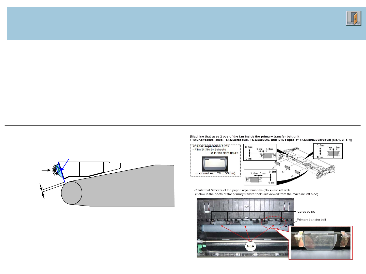
To prevent J31/J4X and the paper wrapping around the primary transfer belt, the paper separation films (No.8, 9) are affixed in between the guide pulleys at
the machine left side of the primary transfer belt.
The paper separation film (2 each sheets of No.8, 9 or 3 sheets of No.9) and the instruction leaflet are bundled in the primary transfer belt unit for service
(No.1-7) and MK kit A.
State after affixing the paper separation film (No.8, 9)
Papr separation film: below is the state that the film is affixed in 0mm of the
vertical alignment. (Please refer to the page 3, 4 for the alignment.)
Guide pulley
About 1.35mm
(Detailed information you will find in SB 2H7-0072-A283)
Primary transfer belt
Page 5
TASKALFA- 250ci, 300ci, 400ci, 500ci, 552ci, FS-C8500DN
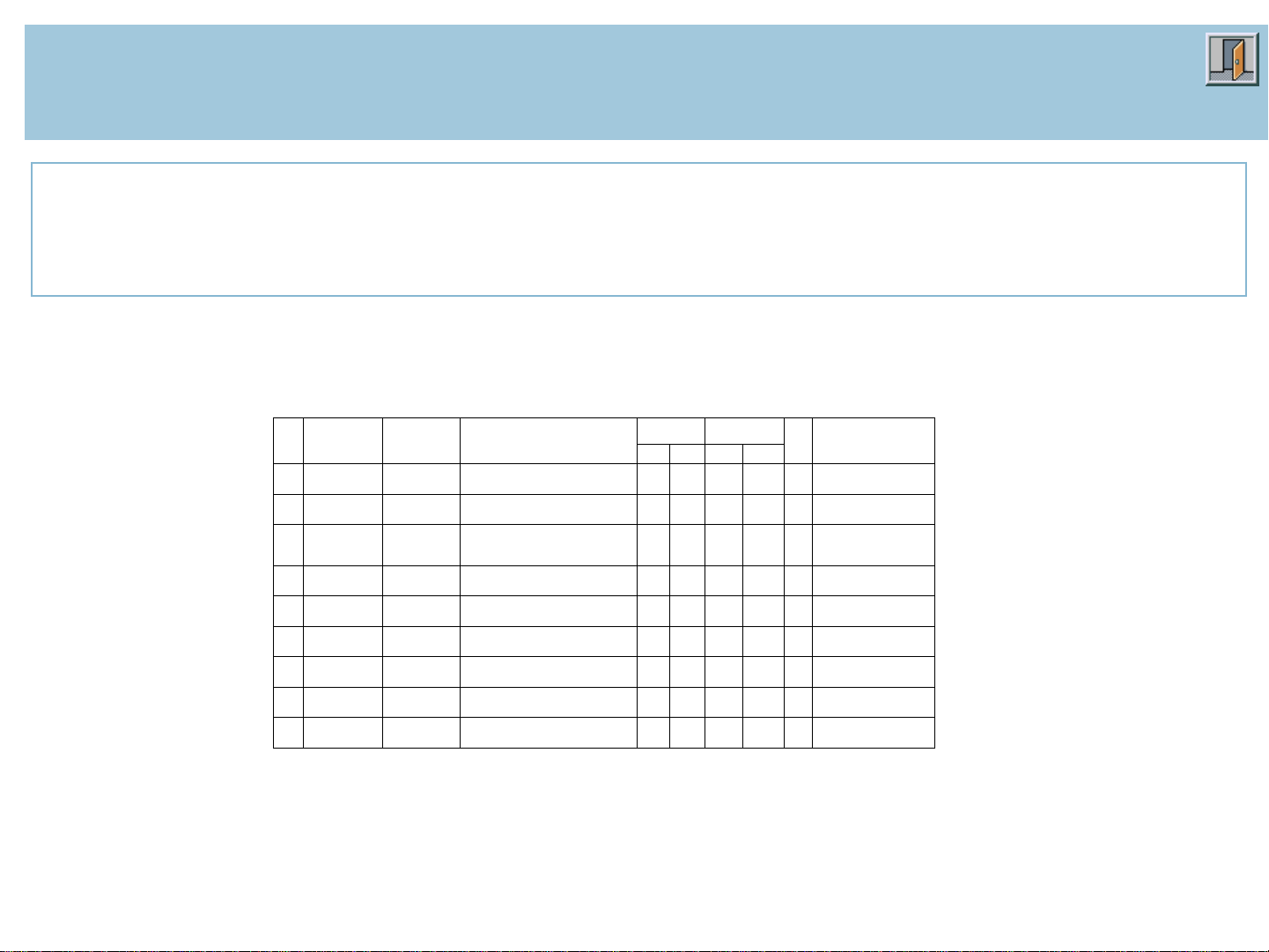
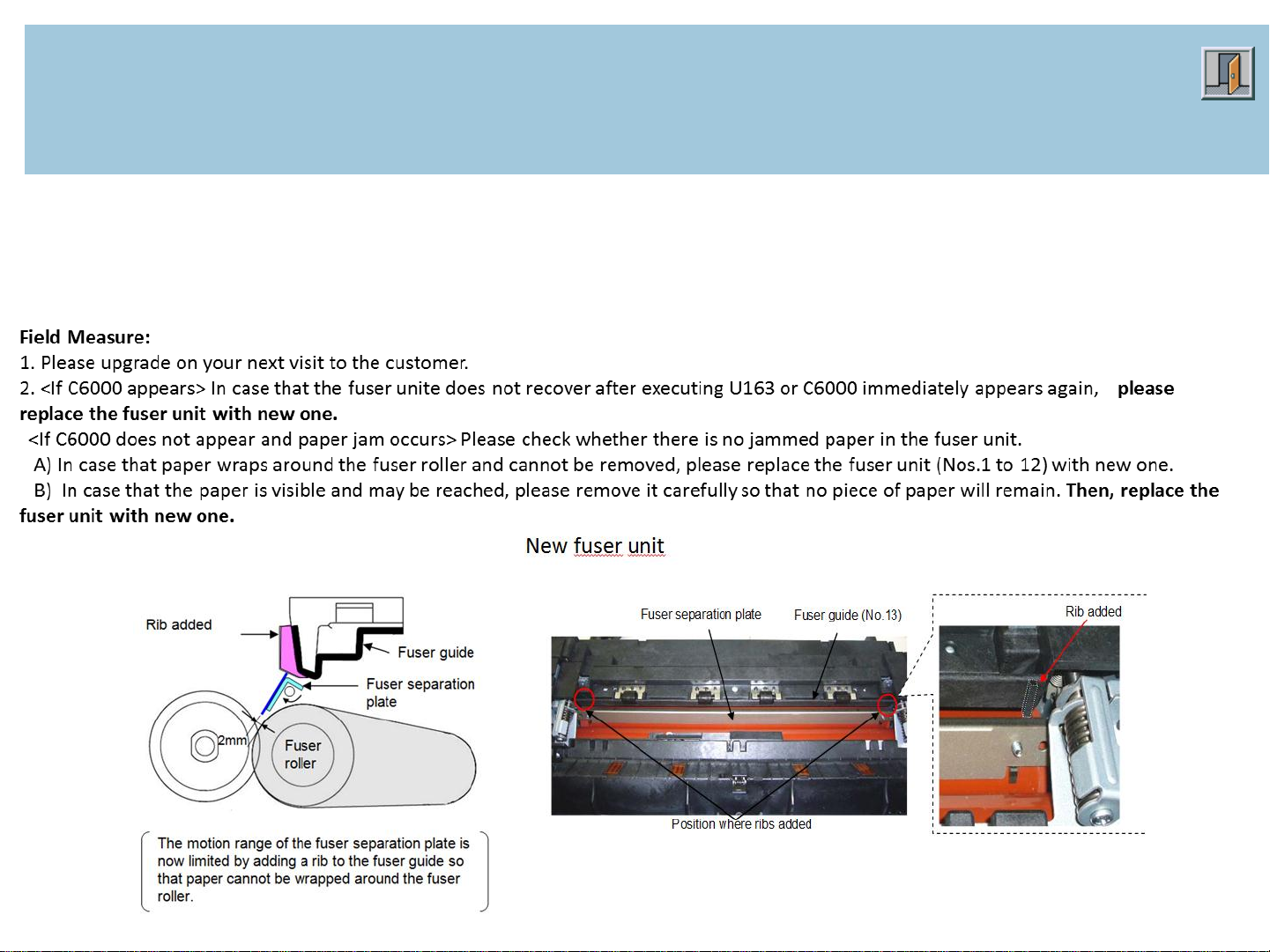
Field Measure:
When the phenomena described in the previous page occur, please affix the paper separation film (No.8, 9) after cleaning the
(When affixing the film, please remove the fuser unit and slightly pull the primary transfer belt unit leftward.)
And, when replacing the primary transfer belt unit or MK kit A, please clean the affixing position with alcohol and affix the
that is bundled.
[Note] Please check if the paper separation film does not contact the primary transfer belt after affixing the film.
No.
Old Part
No.
New Part
No.
Description
Q’
ty
Com
bi
pati
lity
SP
Remarks
Old
New
Old
New
1
302H793226
2H793226
302H793227
2H793227
PARTS TRANSFER BELT H
UNIT
1
1
X O O
500ci/400ci
(Except KMKR)
2
302H79K226
2H79K226
302H79K227
2H79K227
PARTS TRANSFER BELT H
UNIT
1
1
X O O
500ci/400ci
(KMKR)
3
302JZ93076
2JZ93076
302JZ93077
2JZ93077
PARTS TRANSFER BELT L
UNIT
1
1
X O O
300ci/250ci
(Except
KTST/KMKR spec)
4
302JZ9K076
2JZ9K076
302JZ9K077
2JZ9K077
PARTS TRANSFER BELT L
UNIT
1
1
X O O
300ci/250ci
(KMKR spec)
5
302JZ93246
2JZ93246
302JZ93247
2JZ93247
PARTS TRANSFER BELT L J
UNIT
1
1
X O O
300ci/250ci
(KTST spec)
6
302KY93151
2KY93151
302KY93152
2KY93152
PARTS TRANSFER BELT
UNIT
1
1
X O O
*1
(Except KMKR spec)
7
302KY9K151
2KY9K151
302KY9K152
2KY9K152
PARTS TRANSFER BELT
UNIT
1
1
X O O
*1
(KMKR spec)
8
------------
302H721670
2H721670
+FILM GUIDE BELT A
-
(*2)
- O -
9
------------
302H721680
2H721680
+FILM GUIDE BELT B
-
(*2)
- O -
Parts with “O” indicates regular maintenance parts. "+" Mark at the head of the description means it is a components parts.
(*) As for the primary transfer belt unit for service (No.1-7) and MK kit A, the paper separation film (2 each sheets of the film
(No.8, 9) or 3 sheets of No.9) and the instruction leaflet A/B that directs affixing the paper separation film (the attached
leaflet) are bundled.
*1: 552ci, FS-C8500DN
*2: - Primary transfer belt unit (No.3, 4): 2 each sheets of the film A (No.8) and the film B (No.9) are affixed. (Total 4 sheets)
- Primary transfer belt unit (No.1, 2, 5-7): 3 sheets of the film (No.9) are affixed.
TROUBLESHOOTING GUIDE
Preventing wrapped paper in transfer (Measure against J31/J4X) PAGE 5
affixing position of the primary transfer belt with alcohol.
paper separation film (No.8, 9) after fitting the guide pulley
When the paper is wrapping around the upper side of the primary transfer belt, if the end user does not notice the paper and only opens and
closes the cover, the paper is not removed because only the paper jam indication disappear by opening/closing the cover. If continuing drive
in that state, the paper may enter into the inner part of the primary transfer belt and then the cleaning failure at the primary transfer belt
may occur.
5
(Detailed information you will find in SB 2H7-0072-A283)
Page 6
TASKALFA- 250ci, 300ci, 400ci, 500ci, 552ci, FS-C8500DN
TROUBLESHOOTING GUIDE
Preventing wrapped paper into the FK (Measure against C6000, J4X/J50)
PAGE 6
Phenomenon:
In case that a paper jam occurs at the fuser section and the job separator (*), the next fed paper might be pleated when it hits the jammed paper or a piece of torn paper
remaining after clearing the paper jam. Then, the trailing edge of this paper may wrap around the fuser roller.
If the phenomenon described above arises, it is difficult to clear the paper jam and C6000 (Service call detecting fuser problems) may appear. Therefore, the following
changes were made.
(*: J4x/J5x is detected.)
6
(Detailed information you will find in SB 2H7-0075-A333)
Page 7

TASKALFA- 250ci, 300ci, 400ci, 500ci, 552ci, FS-C8500DN
<Fitting procedures of the new fuser guide (No.13)>
*Please handle the fuser unit after cooling it down as it is hot.
1. Fit the new fuser guide (No.13) and fix it by tightening the screws (x3).
2. Check if there is gap between the fuser separation plate and the two ribs added to the fuser guide after the new
fuser guide (No.13) was attached.
3. In case that there is no gap, please add the washer (No.14).
* The method above is how to check the rib on the machine front side. Please check the rib on the machine rear
side by the same way.
Rib added
Fuser separation plate
Please confirm the
gap in the method
described above.
<Plate to check the gap>
Please use the plate which
indicates the size of papers in
cassette.
Please insert the plate between the fuser separation plate and
the ribs added to the fuser guide. In case that there is no gap,
please add the washer (No.14) to the following position.
Fuser guide (No.13)
TROUBLESHOOTING GUIDE
Preventing wrapped paper into the FK (Measure against C6000, J4X/J50)
PAGE 7
7
(Detailed information you will find in SB 2H7-0075-A333)
Page 8

TASKALFA- 250ci, 300ci, 400ci, 500ci, 552ci, FS-C8500DN
Serial Nos. of the Affected Machines:
TASKalfa500ci
KME
UTAX/TA
QHW0Y02513-
Next production
TASKalfa400ci
KME
UTAX/TA
QJA0Y04486-
QES0Y01114-
TASKalfa300ci
KME
UTAX/TA
QJE0Y06328-
QER0Y01758-
TASKalfa250ci
KME
UTAX/TA
QJK0Y28959-
QEQ0Y11614-
TASKalfa552ci
KME
UTAX/TA
QXG0Y00242-
Q4W0Y00082-
<Serial number of the MK kit>
MK-855A for TASKalfa500ci/400ci (KME): From QJR0Y02021 (S/N of FK unit: from MCL0Y00022-)
MK-865A for TASKalfa300ci/250ci (KME): From QJP0Y01914 (S/N of FK unit: from MCM0Y00066-)
TROUBLESHOOTING GUIDE
Preventing wrapped paper into the FK (Measure against C6000, J4X/J50)
PAGE 8
8
(Detailed information you will find in SB 2H7-0075-A333)
Page 9

TASKALFA- 250ci, 300ci, 400ci, 500ci, 552ci, FS-C8500DN
Content of Changes
1) The tolerance for frictional wear of the brush was improved by changing the motor from a different vender.
2) Due to the change above, the shape of the motor holder was changed.
* The holder shape was changed due to the motor change.
As the countermeasure against the Service Call C2810, it is necessary to replace the old PARTS ICL
MOTOR UNIT with the new one (No. 1, 2).
3) Due to the change above, the wire alignment of the motor was changed. (Please refer to the next page.)
No.1,2
No.3
GEAR WORM /48390M0062 A4
(5MVG115DB002)
No.4
<Difference between the old and new PARTS ICL MOTOR UNIT
(Nos.1 and 2)>
White marking added on the new holder
(Nos.1 and 2)
TROUBLESHOOTING GUIDE
Change of the Waste Toner Motor (Measure against the Service Call C2810)
PAGE 9
Phenomenon:
When excessive electrical current was applied to the waste toner motor by short circuit, the engine PWB might be damaged or C2810 (waste
toner motor error) might appear. Therefore, the following changes were made.
Accordingly, some attention is required when replacing the parts. Please refer to <Field Measure> below.
Field Measure:
Please replace the assembly (new No.1, 2) with the new motor and the new holder when the phenomenon described above occurs with
the machine from the October 2009 production up to the one with the serial numbers listed below. (*No problem is expected from the
machines from the September 2009 production and before.)
Serial Numbers list of the Reworked Machines you can find in SB 2H7-0081-B022
9
(Detailed information you will find in SB 2H7-0081 (B022)
Page 10

TASKALFA- 250ci, 300ci, 400ci, 500ci, 552ci, FS-C8500DN
A) Affected models : TASKalfa500ci/400ci/300ci/250ci
(Old) (New)
B) Affected models: TASKalfa552ci, FS-C8500DN
(Old) (New)
1) The position to fit the wire saddle (X) was changed.
2) Do not pass the wire through the wire saddle (Y).
Wire saddle (Z)
Wire saddle (Z)
Do not pass the wire through the wire saddle (Z).
Only the wire of the fan passes through the wire saddle
(Z).
No.1,2
Wire saddle(X)
Wire saddle (Y)
No.1,2
Wire saddle(X)
Wire saddle (Y)
TROUBLESHOOTING GUIDE
Change of the Waste Toner Motor (Measure against the Service Call C2810)
PAGE 10
10
(Detailed information you will find in SB 2H7-0081 (B022)
Page 11

TASKALFA- 250ci, 300ci, 400ci, 500ci, 552ci, FS-C8500DN
TROUBLESHOOTING GUIDE
Change of the Waste Toner Motor (Measure against the Service Call C2810)
PAGE 11
11
(Detailed information you will find in SB 2H7-0081 (B022)
• "+" Mark at the head of the description indicates that it ismponent part.
*1: The old No.4 will be continuously supplied as toner replenishing motor (4
pcs. used). Please use the new Nos.1 and 2 when the waste toner a comotor
is replaced since the new individual waste toner motor is not supplied to
prevent the wrong use as the toner replenishing motor.
Page 12

TASKALFA- 250ci, 300ci, 400ci, 500ci, 552ci, FS-C8500DN
TROUBLESHOOTING GUIDE
Change of the Waste Toner Motor (Measure against the Service Call C2810)
PAGE 12
12
(Detailed information you will find in SB 2H7-0081 (B022)
Page 13

TASKALFA- 250ci, 300ci, 400ci, 500ci, 552ci, FS-C8500DN
TROUBLESHOOTING GUIDE
Prevention of the DV toner dropping PAGE 13
Phenomenon:
Depending on the operating environment (*), the cohesive materials of the deteriorated toner and the additives peeled off from
the toner may accumulate on the topside of the Bk developer magnet cover and it may interrupt air flow of the developer cooling
fan. If the deteriorated toner accumulates on the cohesive materials and adheres to the magnet/sleeve roller, Bk toner smudge
may appear. Therefore, following are changed.
(*) Bk toner smudge easily appear if the temperature inside the machine rises due to driving for a long time, or the originals/data
of low print coverage are continuously printed out in monochrome mode.
(The above causes the increase of the deteriorated toner)
Content of changes:
(Refer to next page for details)
1) Bk developer units for preventing the
toner smudge (No.1-4) are set and
supplied for the field.
Bk developer units for preventing the toner
smudge are not brought to the machine
produced in the factory because use of
these units is accompanied with the
restriction.
Following are the changed points from the
normal Bk developer unit.
(Refer to the next page for restriction.)
Image sample
2) Firmware is upgraded as below.
3) According to setting the parts No. of the Bk developer unit for
preventing the toner smudge in the above 1), indication and check
box of [DV-855B], [DV-865B] and [DV-856B] are added to the
packing case that is commonly used with the normal developer unit
(DV-855/865/856 for four colors).
13
(Detailed information you will find in SB 2H7-0080 (B010)
Page 14

TASKALFA- 250ci, 300ci, 400ci, 500ci, 552ci, FS-C8500DN
TROUBLESHOOTING GUIDE
Prevention of the DV toner dropping PAGE 14
Changed point:
Firmware changes:
14
(Detailed information you will find in SB 2H7-0080 (B010)
Page 15

TASKALFA- 250ci, 300ci, 400ci, 500ci, 552ci, FS-C8500DN
Please recognize the following because use of the Bk developer unit for preventing the toner smudge (No.1-4)
is accompanied with the restriction.
Content for restriction
Related change
(Refer to the previous page)
1
Please explain the sound that is heard when the coupling of the main
machine side and the developer side mesh with each other for reversely
rotating the developer drive to the user for acquiring the user's approval. (*1)
<Changed point 3>
Firmware upgrade
(*1) If the user does not approve the content of restriction 1, please use the normal Bk developer unit.
(These units are only for supply to the field.)
No.
Old Part
No.
New Part
No.
Description
Q’
ty
Com
bi
pati
lity
Remarks
Old
New
Old
New
1
------------
302H793710
2H793710
PARTS DLP K UNIT B
-
1
-
O
*1,
DV-855B (Except KMKR)
2
------------
302H79K710
2H79K710
PARTS DLP K UNIT B
-
1
-
O
*1,
DV-855B (For KMKR)
3
------------
302JZ93410
2JZ93410
PARTS DLP K L UNIT B
-
1
-
O
*2,
DV-865B (Except KMKR)
4
------------
302JZ9K410
2JZ9K410
PARTS DLP K L UNIT B
-
1
-
O
*2,
DV-865B (For KMKR)
5
------------
302H794830
2H794830
PARTS SEAL FRONT DRUM
SET SP
-
1
-
O
Seal kit for replacing the
drum unit, *3
*1: TASKalfa500ci/400ci (Normal Bk developer unit --- For all spec except KMKR: 302H79317_/For KMKR: 302H79K17_)
*2: TASKalfa300ci/250ci (Normal Bk developer unit --- For all spec except KMKR: 302JZ9319_/For KMKR: 302JZ9K19_)
*3: Bundled items of No.5 (That are same as the parts that are bundled in No.1-4 in <Changed point 4> mentioned in the
previous page) --- Sponge (L), sponge (S), seal and affixing procedure leaflet
* Developer drive gear of the normal developer unit is individually supplied. However, the developer drive gear (The shape is
changed from the gear of the normal developer unit in <Changed points> 3) of the Bk developer unit for preventing the toner
smudge (No.1-4) is not set as the individual supply parts.
TROUBLESHOOTING GUIDE
Prevention of the DV toner dropping PAGE 15
Restriction
Developer unit for preventing the toner smudge and seal kit
15
(Detailed information you will find in SB 2H7-0080 (B010)
Page 16

TASKALFA- 250ci, 300ci, 400ci, 500ci, 552ci, FS-C8500DN
TROUBLESHOOTING GUIDE
Transferbelt cleaning failure PAGE 16
Phenomenon:
Abnormal image (offset image) may be
printed out caused by the cleaning failure on
the transfer belt due to the cleaning ability.
(New fur brush)
Counter measure:
When the above phenomenon occurs,
please replace with the new fur brush as it is
shown in the Service Bulletin (2H7-0092-
C274).
Parts information:
PARTS BRUSH FUR B SP (302KY94370)
16
(Refering to SB 2H7-0092-C274)
Page 17

This technical publication is confidential information that is the property of Kyocera Document Solutions. It is solely
for the use of Kyocera Document Solutions authorized dealers. This information may not be published, reproduced,
sold, or copied in any media. This document contains published service bulletin information; it is to help you
troubleshoot specififc problems. Using the troubleshooting guide does not release you from your responsibility as
a technician to abide by the country laws and company regulations that you are already bound to.
We can not be held liable for any action on your part that is not strictly specified in this document.
©KYOCERA Document Solutions Europe B.V.
Published by:
PRODUCT ENGINEERING
Technical Documentation
Released: 23 January 2013
 Loading...