

Page 1

Print/Scan System (L)
INSTRUCTION HANDBOOK
AL WAYS read this Instruction Handbook thoroughly before use. After reading, maintain it in good condition and
keep it together with the Instruction Handbook for your copier.
Page 2

Trademark Information
• MS-DOS, Windows and Windows NT are trademarks of Microsoft Corporation.
• PCL is a registered trademark of Hewlett-Pac kard Company.
• PostScript is a registered trademark of Adobe Systems Incorporated.
• Ethernet is a registered trademark of Xerox Corporation.
• Novell and NetWare are registered trademarks of Novell, Inc.
• Centronics is a trademark of Centronics Data Computer Corporation.
• IBM and IBM PC-AT are trademarks of International Business Machines Corporation.
• PowerPC is a trademark of International Business Machines Corporation of America and other corporations.
• TrueType is a registered trademark of Apple Computer, Inc.
• This product was developed using Tornado, the real-time operating system (ROTS) general development environment
from Wind River Systems, Inc.
• This printer uses PeerlessPrintXL, a PCL compatibility system developed by Peerless Group, to emulate the HP
LaserJet Printer Control Language (PCL6). PeerlessPrintXL is a trademark of Peerless Group (Redondo Beach, CA
90278, U.S.A.).
• KPDL is a trademark of Kyocera Corporation.
All other company and product names contained in this Instruction Handbook are trademarks or registered trademarks of
their respective companies. The designations ™ and ® will not be used in this handbook.
About this Instruction Handbook
This Instruction Handbook is meant to be read when the Printer Board is installed in your copier and the copier is to be
used as a printer, as well as when the Scanner Board is installed and the copier is to be used as a scanner. It explains
operations on using the machine as a printer and a scanner as well as installing the included software for either purpose.
As the required set-up and configurations for the printer or scanner may differ depending upon the environment in use in
the connected computer, please read those sections related to your specific computer environment and perform the
appropriate set-up and configuration explained there. It is additionally recommended that set-up and configuration be
performed under your network administrator's instructions and observation.
This handbook should also be read and used together with the appropriate On-Line Manual that is on the included
CD-ROMs. Refer to the following "Using the On-Line Manual".
i
Page 3

Using the On-Line Manual
The CD-ROMs included with this product contain a PDF (Printer Description File) that explains how to use the required
applications when using your copier as a printer or a scanner. The included CD-ROMs are as follows:
● CD-ROM (Printer edition)
• Printer Driver for Windows 95 and Windows 98
• Printer Driver for Windows NT 4.0
• Printer Driver for Windows 2000
• Utilities
● CD-ROM (Scanner edition)
• Installing the Network Scanner System
• Basic Image Scanning
• Utilities
Opening the On-Line Manual
Carry out the following procedure to open and view the On-Line Manual.
1. Insert the appropriate CD-ROM (Printer or Scanner edition) into the CD-ROM drive of your computer. The Main Menu
screen for set-up will automatically appear.
2. Click on Documents in the Main Menu screen in order to access the desired On-Line Manual
for viewing.
ii
Page 4

Contents
Section 1 Preparation (Printer/Scanner) ............................................ 1-1
1-1 Names of Parts ................................................................................................1-1
● Main Body ....................................................................................................1-1
● Operation Panel ...........................................................................................1-1
1-2 Accessories......................................................................................................1-2
1-3 Included Software (main contents of CD-ROMs) .............................................1-2
1-4 Required Items.................................................................................................1-2
Section 2 Using the Printer ................................................................. 2-1
2-1 Setting up the Printer .......................................................................................2-1
(1) Connecting the printer cable.......................................................................2-1
(2) Installing the Printing System software.......................................................2-1
2-2 Installing the Printer Driver...............................................................................2-2
(1) System Conditions......................................................................................2-2
(2) Installing the Printer Driver .........................................................................2-3
2-3 Paper ...............................................................................................................2-5
(1) Paper acceptable for the drawer ................................................................2-5
(2) Paper acceptable for the stack bypass tray................................................2-5
2-4 Operation .........................................................................................................2-7
(1) Issuing printing commands.........................................................................2-7
(2) Canceling printing.......................................................................................2-8
(3) FORM FEED (Force-printing).....................................................................2-8
2-5 Printer Configuration ........................................................................................2-9
(1) Making a test print ......................................................................................2-9
(2) Printer default settings................................................................................2-9
(3) Network settings ....................................................................................... 2-11
(4) Making settings in the Job Storage tab ....................................................2-13
(5) Printing when the management function is on..........................................2-14
2-6 When This Message is Displayed ..................................................................2-15
2-7 Troubleshooting .............................................................................................2-17
(1) When you think there is trouble ................................................................2-17
2-8 Specifications .................................................................................................2-18
Section 3 Using the Scanner............................................................... 3-1
3-1 Setting Up the Scanner ....................................................................................3-1
(1) Outline and Network Diagram ....................................................................3-1
(2) Connecting the Scanner to the Computer Network ....................................3-2
(3) Changing the Network Default Settings .....................................................3-2
● Setting the Scanner Address ......................................................................3-3
● DHCP Setting..............................................................................................3-3
● Changing the Management Pin Code for the Scanner ...............................3-3
3-2 Setting Up the Scanner Software.....................................................................3-4
(1) System requirements..................................................................................3-4
(2) Using the Network Scanner........................................................................3-5
(3) Installing the Scanner Driver (TWAIN) .......................................................3-5
(4) Installing the Required Utility ......................................................................3-5
3-3 Operation at the Scanner .................................................................................3-6
(1) Scanning an Image Using TWAIN..............................................................3-6
(2) Scanning & Sending an Image Using PCScan...........................................3-6
(3) Sending an Image Using E-mail .................................................................3-8
(4) The Function Set-up Screen.......................................................................3-9
3-4 Troubleshooting ............................................................................................. 3-11
3-5 Scanner Specifications ..................................................................................3-12
iii
Page 5
Section 1 Preparation (Printer/Scanner)
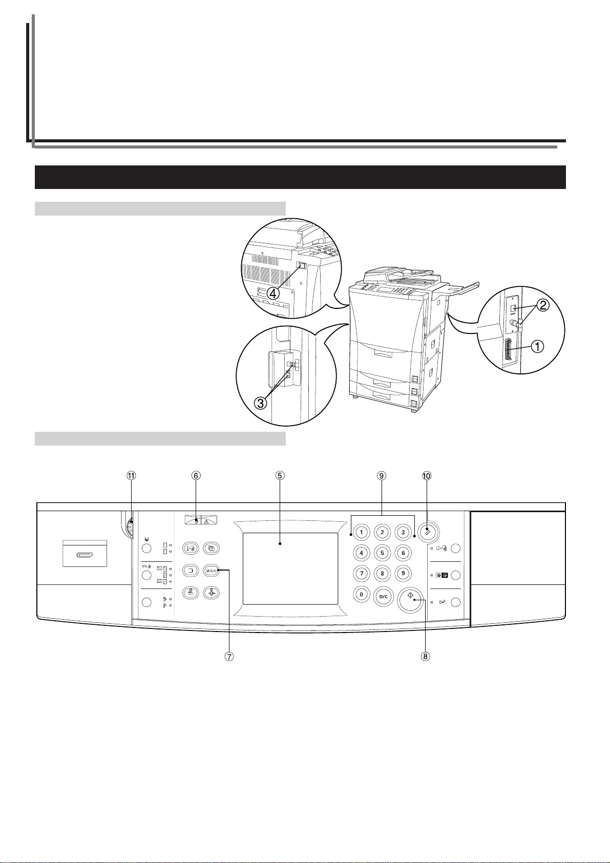
1-1 Names of Parts
● Main Body
1 Parallel interface connector
Connect a bi-directional parallel cable here
when you will use the copier as a local
printer.
2 Ethernet cable connector A
Connect a 10BASE-T, 100BASE-TX or
10BASE-2 cable here when you will use the
copier as a network printer.
3 Ethernet cable connector B
Connect a 10BASE-T, 100BASE-TX or
10BASE-2 cable here when you will use the
copier as a network scanner.
4 Main switch
Turn this switch ON ( | ) first, prior to using
the printer or scanner.
● Operation Panel
5 T ouch panel
Displays the various operation menus, etc., as well as indicating
the status of the machine. Set-up and configuration is accomplished by lightly touching the corresponding area on the panel.
* DO NOT press on the panel with pointed objects or wooden,
metal or other hard objects. All keys, tabs and indications shown
on the touch panel will be referred to throughout this handbook
in quotation marks.
6 Data/Error indicator
Blinks or lights during communication with a computer. Blinks or
lights red when an error has occurred during communication.
7 Copier/Printer/Scanner key
Press this key to switch between copy, printer and scanning
operation.
8 Start key
Set the desired original and press this key to start the scanning
operation.
9 Numeric keys
Press these keys when you want to enter a desired value for one
of the various settings.
0 Reset key
Press this key when you want to reset a value that was entered
for one of the various settings.
! Brightness adjustment control dial
Turn this dial when you want to adjust the brightness of the touch
panel.
1-1
Page 6

Section 1 Preparation (Printer/Scanner)
1-2 Accessories
Prior to using the printer/scanner for the first time, verify that the following accessories are included with this product.
• 1 CD-ROM (Printer Drivers)
• 1 CD-ROM (Scanner Utilities)
• 1 CD-ROM (TWAIN-compatible application)
• NIC (Network Interface Card) [For Scanner]
• Instruction Handbook
1-3 Included Software (main contents of CD-ROMs)
● CD-ROM (Printer Drivers)
• Printer Drivers
• Printer Utilites
• Acrobat Reader
• On-Line Manual
● CD-ROM (Scanner Utilities)
• Scanner File Utility
• Scanner Delivery Utility
• Network TWAIN Source
• Acrobat Reader
• On-Line Manual
Preparation (Printer/Scanner)
Using the Printer
1-4 Required Items
You must have on hand one of the following cables as appropriate to your computer network environment.
• Parallel cable (IEEE 1284 compliant)
• 100BASE-TX
• 10BASE-T
• 10BASE-2
* If you purchase the optional Network Card for the Printer, it will be
possible to use this copier as a network printer. For details, contact
your service representative or service centre.
* When you use a 10BASE-T or 100BASE-TX cable, make sure it is a shielded cable.
Using the Scanner
1-2
Page 7
Section 2Using the Printer
2-1 Setting up the Printer
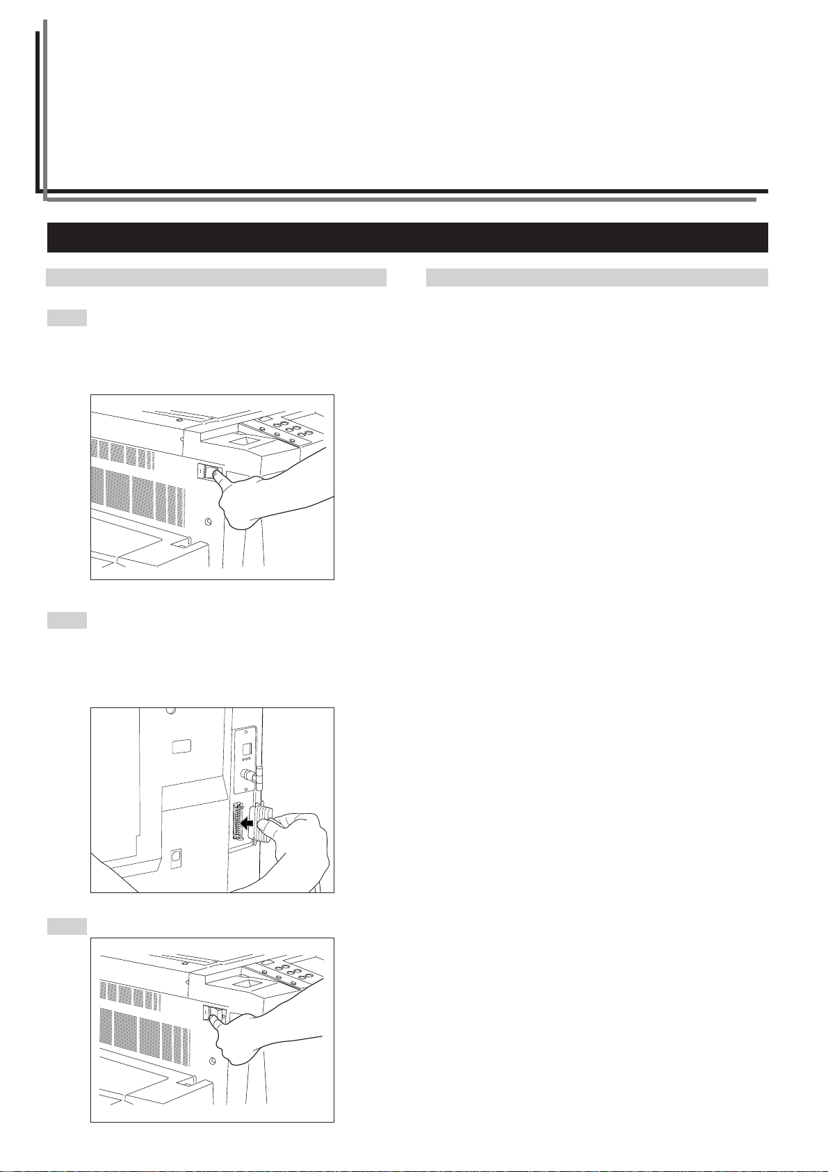
(1) Connecting the printer cable
Caution
1
ALWAYS turn the printer and the computer OFF before
connecting the printer cable.
Turn the main switch, located on the left side of the printer,
OFF (O).
Connect a printer cable to the parallel interface connector or
2
Ethernet cable connector that is located on the right rear
side of the machine.
* If you are connected to a network through a Ethernet
connection, it is necessary to make the appropriate
network settings. (Refer to “(3) Network settings”,
page 2-11.)
(2) Installing the Printing System software
Carry out the following procedure to install the Printing System
software that is appropriate to the operating system that is in use on
your computer.
The following Printing System software is available with this product.
• Printer Drivers
• Printer Manuals
• Printer Utility softs
Refer to the corresponding section for the appropriate installation
procedure for each software package.
* The printer is compatible for use with computers running
Windows 98.
Refer to the explanations for Windows 95 when attempting to
perform set-up and operational procedures under Windows 98.
3
2-1
Turn the main switch to the printer back ON ( | ).
Page 8
Section 2 Using the Printer
2-2 Installing the Printer Driver
This chapter explains the required operating conditions for the printer driver and how to install it. The printer driver hands over the print data
created by Windows applications to the printer.
* For details of the functions of the printer driver, refer to the “Printing System On Line Manual” of the Printing System instruction manual.
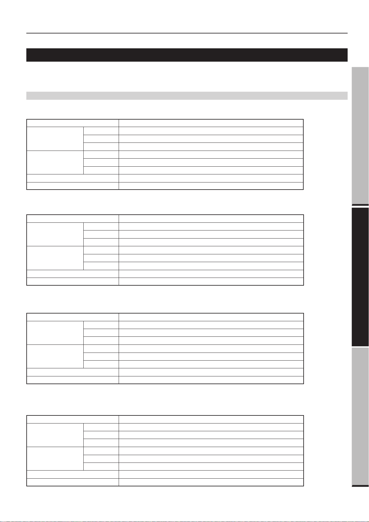
(1) System Conditions
● Windows 95
Operating system IBM PC / AT or compatible
System
requirements
Recomended
requirements
CD-ROM drive
Parallel interface port
● Windows 98
CPU
RAM
HDD
CPU
RAM
HDD
i486SX 25 MHz or more
8 MB or more
10 MB or more
Pentium 90 MHz or more
16 MB or more
10 MB or more
1 drive
IEEE 1284 1port
Preparation (Printer/Scanner)
Operating IBM PC / AT or compatible
System
requirements
Recomended
requirements
CD-ROM drive
Parallel interface port
● Windows NT 4.0
Operating IBM PC / AT or compatible
System
requirements
Recomended
requirements
CD-ROM drive
Parallel interface port
CPU
RAM
HDD
CPU
RAM
HDD
CPU
RAM
HDD
CPU
RAM
HDD
i486DX 66 MHz or more
16 MB or more
10 MB or more
Pentium 90 MHz or more
32 MB or more
10 MB or more
1 drive
IEEE 1284 1port
i486SX 25 MHz or more
16 MB or more
10 MB or more
Pentium 90 MHz or more
32 MB or more
10 MB or more
1 drive
IEEE 1284 1port
Using the Printer
Using the Scanner
● Windows 2000
Operating IBM PC / AT or compatible
System
requirements
Recomended
requirements
CD-ROM drive
Parallel interface port
CPU
RAM
HDD
CPU
RAM
HDD
Pentium 133 MHz or more
64MB or more
10 MB or more
Pentium 133 MHz or more
64 MB or more
10 MB or more
1 drive
IEEE 1284 1port
2-2
Page 9
Section 2 Using the Printer
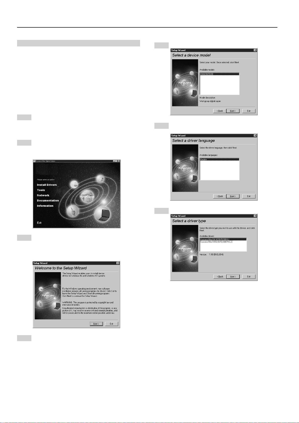
(2) Installing the Printer Driver
Install the printer driver as follows:
* The printer can be connected to the computer by one of the
following two methods: local or network. If you want to connect
them through network, refer to the operation manual of the
operating system (OS).
* The screens shown in the following explanation are those
displayed when installing the printer driver for Windows 95/98.
* The actual screen is still under development for Windows 95/98
(English OS).
Start Windows 95, Windows 98, Windows NT or
1
Windows 2000.
* If any applications are currently running, exit them.
Insert the CD-ROM supplied with the printer into the
2
CD-ROM drive.
A start window will appear.
Select the printer you are using, then click Next.
5
The language to be used can be selected. Select the
6
desired language from the box, then click Next.
Click Install Driver in the lower left corner of the window.
3
* If the start window does not appear even if the CD-ROM is
inserted, double-click My Computer on the desktop, then
double-click the CD-ROM icon.
The Setup Wizard window will appear, so click Next.
4
A list of printer models will appear.
Select the driver type.
7
From the list, select the type of driver to be installed, then
click Next.
* (XL) Driver: Extension Driver for Windows 95/98
KPDL2 Driver: Adobe PostScript2 Printer Driver
2-3
Page 10
Section 2 Using the Printer
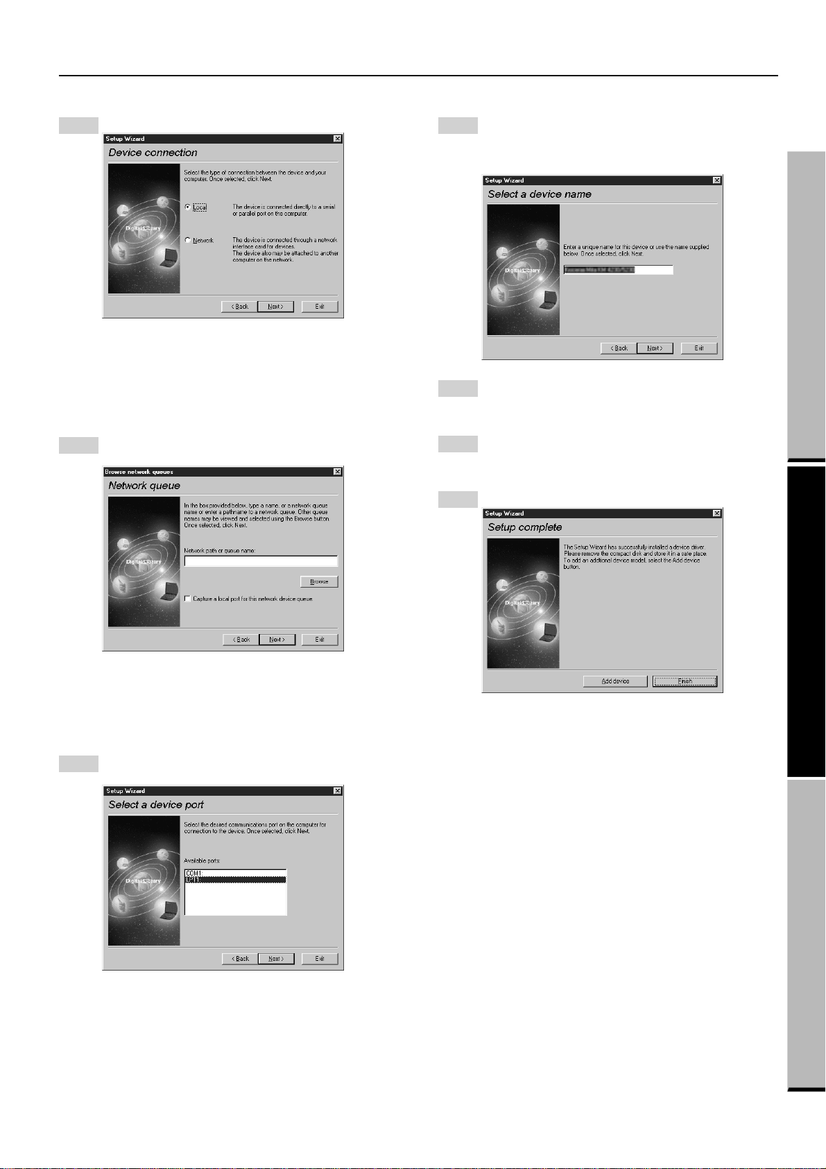
Select the connection type: Local or Network.
8
• Local: The printer is connected directly to the parallel port.
• Network: The printer is connected to the printer via
network (using a network interface).
* If Local is selected, proceed to step 10. If Network is
selected, proceed to step 9.
Enter the network queue name or the path for the network
9
queue in the box.
A name can be assigned to your printer.
11
Specify a new name or select the desired name from the
list, then click Next.
Installation of the printer driver will start.
Specify whether this printer is to be used as the default
12
printer.
Click Yes if so, or click No if not.
The settings you have made so far will appear. If they are
13
correct, click Next.
Installation of the printer driver will start.
To exit installation, click End.
14
Preparation (Printer/Scanner)
To select another network queue name, press Browse.
If you are going to use a local port for the network queue,
click the check box displayed below, then proceed to
step 10.
Otherwise, proceed to step 11.
Select a printer port. From the list, select the desired port,
10
then click Next.
Using the Printer
* If you want to add another printer driver, click Add Printer
and then repeat the same procedure.
Installation of the printer driver is now complete.
Using the Scanner
* Normally, set to LPT1.
* When installing the printer driver for Windows NT, the Add
LPR Port button will appear below the box, so press the
button to set the desired LPR printer.
2-4
Page 11
Section 2 Using the Printer
2-3 Paper
(1) Paper acceptable for the drawer
• Plain paper (64 g/m2): 500 sheets
• Recycled paper (64 g/m2): 500 sheets
• Color paper (64 g/m2): 500 sheets
* Acceptable weight: 64 g/m2 - 80 g/m
* Acceptable sizes: A5R - A3, Folio
* For information regarding setting paper, refer to the Instruction
Handbook for your copier.
2
(2) Paper acceptable for the stack bypass tray
• Plain paper (64 g/m2): 100 sheets
• Recycled paper (64 g/m2): 100 sheets
• OHP transparencies: 25 sheets
• Postcard: 25 sheets
• Envelopes (DL, C5): 10 sheets
● Setting envelopes in the stack bypass tray
Carry out the following procedure when setting envelopes in the
stack bypass tray. Be sure also to enter into the printer’s operation
panel the size of the envelope as it corresponds to the envelope
type. (Refer to the sizes at right and carry out the following procedure
to enter the appropriate size in the operation panel of the printer.)
Envelope Type Size That Should Be Entered
DL 220 mm x 110 mm
C5 229 mm x 162 mm
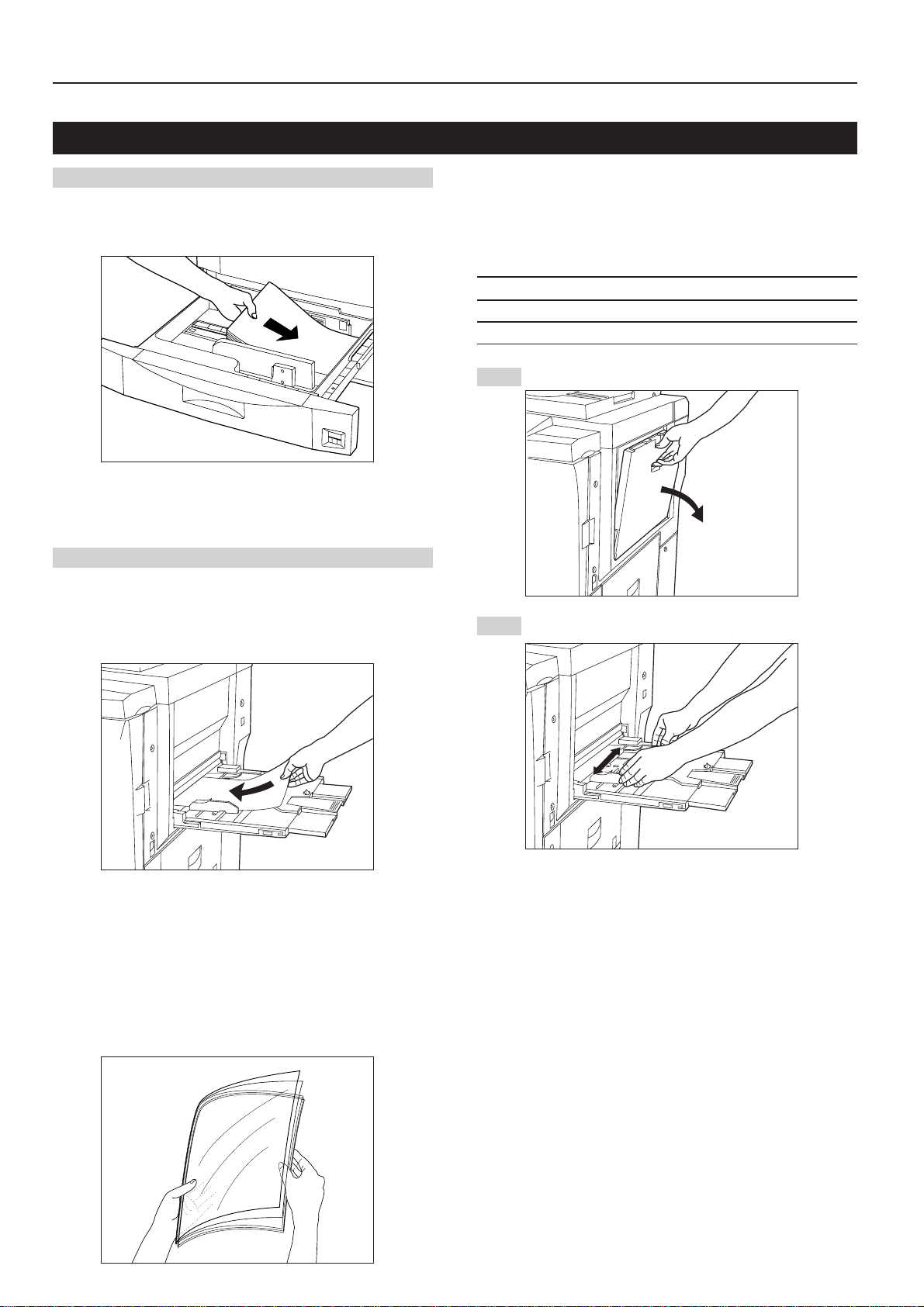
Open the stack bypass tray.
1
Adjust the insert guides to match the size of the envelope.
2
* Acceptable weight: 45 g/m2 - 200 g/m
* Acceptable sizes: A5R - A3, Folio
It is additionally possible to set custom size paper other than those
sizes noted above as long as the dimensions of that paper are
within:
Width: 98 mm - 297 mm, Length: 148 mm - 432 mm
* When using OHP transparencies, flip through them to separate the
sheets before setting them into the stack bypass tray.
* For information regarding setting paper, refer to the Instruction
Handbook for your copier.
2
2-5
Page 12
Section 2 Using the Printer
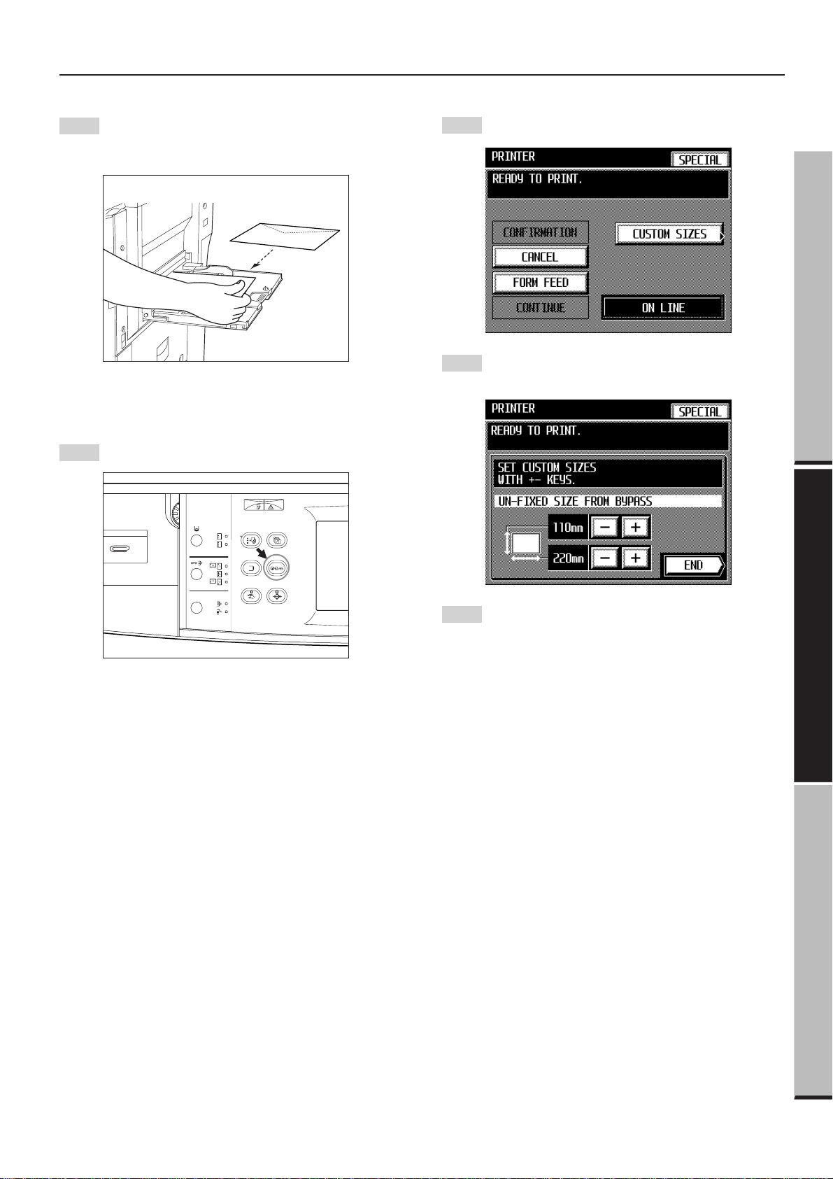
Close the flap on the envelopes and, with the envelopes
3
face up (flap side down) and the flap towards the rear of the
copier, slide them along the guides and into the stack
bypass tray, as far as they will go.
* If a mistake is made in setting an envelope, the direction
of printing and the surface that printing is accomplished
onto will not be as expected.
Press the Copier/Printer/Scanner switching key to switch to
4
the screen for printer operation.
Press the “CUSTOM SIZES” key. The custom size setting
5
screen will appear.
Press the “–” or “+” key to select the desired width and
6
length. The width can be adjusted between 98 mm 297 mm, and the length between 148mm - 432 mm.
Preparation (Printer/Scanner)
Press the “END” key. The message display will return to the
7
printer function screen.
Using the Printer
Using the Scanner
2-6
Page 13

Section 2 Using the Printer
2-4 Operation
(1) Issuing printing commands
Carry out the following procedure in order to issue printing
commands from your computer and print out with this unit.
Turn the main switch ON ( | ).
1
* The basic copier screen will appear on the touch panel
and, once warm up is complete, “READY TO COPY.” will
appear in the message display.
Press the “TO ON LINE” key and “READY TO PRINT.” will
3
appear in the message display. This will signify that the
printer is on-line.
* It is not necessary to press the “TO ON LINE” key if
“READY TO PRINT.” is already displayed.
In your computer, start up the software application to be
4
used.
* Carry out the printing procedure appropriate to the
software application in use. For more detailed information,
refer to the Instruction Manual for the software application
in use.
* DO NOT return to the screen for copier operation and
press the Stop/Clear key during printing. If you do, printing
will be canceled.
Press the Copier/Printer/Scanner switching key to switch to
2
the screen for printer operation.
* If printing commands are issued from your computer
immediately after a copy job is completed in this unit, the
print job may not be started right away. This is because
the copying settings must be cleared in this unit before
printing can begin. Once the Auto Clear function engages
and copy settings are cleared, printing will begin. To
initiate printing immediately, press the Copier/Printer/
Scanner switching key to change to the screen for printer
operation.
2-7
Page 14

Section 2 Using the Printer
(2) Canceling printing
Carry out the following procedure to cancel a print job that has
already been initiated.
* Printing can be cancelled as long as data is still being sent to the
printer (i.e. the data indicator is blinking). However, depending
upon the timing, a portion of the data may still be printed.
Cancel the print job in your computer.
1
* If the print job is not cancelled in your computer, the data
will be sent once again to the printer.
Press the Copier/Printer/Scanner switching key to change to
2
the screen for printer operation.
(3) FORM FEED (Force-printing)
Depending upon the software in use, “Waiting” may appear in the
message display during printing. This occurs when the software has
not sent any commands to the printer indicating that there is no more
print data to be sent. If you wait in this case, the Auto continue
function (page 2-10) will engage and automatically print out the last
page. However, if you press the “FORM FEED” key you can forceprint that page right away. To do this, perform the following
procedure.
* If you force-print a portion of the print job while the computer is still
processing data, “Waiting” might still be displayed if there are more
pages remaining to be printed. Thus, if you press the “FORM
FEED” key when it’s not necessary, printing may not be
accomplished correctly.
Cancel the print job in your computer that contains the page
1
that you are force-printing.
* If the print job is not canceled in your computer, the data
will be sent once again to the printer.
Press the “FORM FEED” key.
2
Pages for which complete data was received from your
computer will be printed out.
Preparation (Printer/Scanner)
Press the “CANCEL” key. Printing will be canceled.
3
Reception of data from your computer is once again
4
possible.
Reception of data from your computer is once again
3
possible.
Using the Printer
Using the Scanner
2-8
Page 15

Section 2 Using the Printer
2-5 Printer Configuration
(1) Making a test print
When the printer is being used for the first time, or when settings in
the printer have been changed, print out a test page to confirm
whether or not printing will be accomplished as expected.
Allows you to print the current printer settings, such as
1
emulation mode, fonts and memory status, to the printer.
Press the “TEST PRINT” key.
2
The test print item select screen will appear.
(2) Printer default settings
Carry out the following procedure to change the default settings for
the Auto continue, Receive buffer and Time out functions that are in
effect when this unit is used as a printer.
After changing the printer setting, press [END] button the recover the
printer to online status, then turn OFF/ON the main switch.
It is only after turning the main switch OFF/ON, the printer setting will
be reflected.
● Accessing the printer default screen
1
Make sure that “OFF LINE” is shown in the message display
(the printer is currently off-line) and press the “SPECIAL”
key. The printer setting screen will appear.
* The Network setting key is displayed only if the network
board is installed. For details, refer to “(3)Network
settings”.
Three test print keys are displayed in the test print item
3
select screen, so press the desired one. A test print will be
made, and when the test print is completed the printer
setting screen will reappear.
11
1 STATUS
11
Prints out the current printer settings (e.g. emulation, fonts, memory
status) to the printer.
22
2 LIST OF RESIDENT FONTS
22
Print outs the fonts that can be printed.
33
3 SERVICE STATUS PAGE
33
Designed for use by service personnel.
Press the “PRINTER DEFAULT” key. The printer default
2
screen will appear.
* To return all of the functions to their initial default settings,
press the “RESTORE DEFAULTS” key.
* Once all desired changes to the default settings are
complete, press the “END” key and the message display
will return to the printer setting screen.
2-9
Page 16

Section 2 Using the Printer
11
1 Auto continue
11
If a printer error such as a paper mismatch error occurs, printing can
be set to restart automatically after the amount of time specified
here. In this case, the print job will NOT be stopped. If, however,
“OFF” is selected here, the print job WILL be stopped whenever a
printing error occurs. If “0 MIN” is selected, the error will be ignored
and printing will continue.
Press the “–” or “+” key to select either “0 MIN”, “2 MIN”, “5 MIN”,
“10 MIN”, “20 MIN” or “OFF”.
* The factory default setting is “2 MIN”.
22
2 Receive buffer
22
The receive buffer function allows you to set the amount of system
memory allocated for data received from the I/F Board to be spooled
before it is printed. Setting the buffer to a larger value allows more
data to be received from the computer, thereby reducing the amount
of computer down time during printing.
44
4 Parallel Interface
44
Both bi-directional and high-speed modes are supported.
Select the desired mode from “AUTO”, “NIBBLE HIGH”, “NORMAL”
and “HIGH-SPEED” using the “–” key or “+” key.
* By default, “AUTO” is selected.
* If the page contained unnecessary pages or unknown character
was printed out, please change the setting and print again.
55
5 Page Protect
55
A print overrun error may occur in case of complex print data. In this
case, select “ON” to allow printing of such data. If “AUTO” is
selected, printing speed will drop slightly.
“AUTO” or “ON” can be selected by using the “–” key or “+” key.
Preparation (Printer/Scanner)
Press the “–” or “+” key to select either “24 KB”, “500 KB”, “700 KB”
or “990 KB”.
* The factory default setting is “500 KB”.
33
3 Form Feed Time Out
33
It is possible to set the maximum amount of time that the printer will
wait to receive data from the computer. If the printer does not receive
any data from the computer within the amount of time specified here,
printing will be cancelled.
Press the “–” or “+” key to select either “30 SEC.”, “60 SEC.”,
“120 SEC.”, “180 SEC.”, “240 SEC.” or “300 SEC.”.
Using the Printer
* By default, “AUTO” is selected.
* For detailed on error messages, refer to “2-6.When This Message
is Displayed…”.
Using the Scanner
* The factory default setting is “30 SEC.”
2-10
Page 17

Section 2 Using the Printer
66
6 Emulation
66
Used to select the printer language. To switch to another emulation
mode, press the Change key.
* Emulation (Network) is displayed only if the network board is
installed.
Open the screen for emulation setting.
1
Press the “–” key or “+” key to display a list of the available
emulation modes, then select the desired one.
(3) Network settings
It is possible to set the Internet Protocol (IP) address, Subnet Mask
and Gateway address.
* These settings should be performed by the network manager or
under that person’s instruction.
After changing the printer setting, press [End] button the recover the
printer to online status, then turn OFF/ON the main switch.
It is only after turning the main switch OFF/ON, the printer setting will
be reflected.
* By default, “PCL 6” is selected.
(The Print KPDL Errors option is displayed only when
KPDL or KPDL (AUTO) is selected. (for overseas version
only).)
“ON” or “OFF” can be selected by using the “–” key or “+”
key.
If KPDL (AUTO) is selected at step 1, the Alternate
2
Emulation option will appear. This allows you to select an
alternate emulation mode in cases when no print can be
made in KPDL mode.
Make sure that “OFF LINE” is shown in the message display
1
(the printer is currently off-line) and press the “SPECIAL”
key. The printer setting screen will appear.
Press the “NETWORK SETTING” key.
2
The Pin code screen will appear.
After changing the printer setting, press [End] button the recover the
printer to online status, then turn OFF/ON the main switch.
It is only after turning the main switch OFF/ON, the printer setting will
be reflected.
2-11
Page 18

Section 2 Using the Printer
Use the numeric keys to enter “6200” (the network
3
management code).
* If the correct code is entered, the network setting screen
will appear.
* This 4-digit code can be changed. Refer to step 6 and
subsequent steps.
Default codes: 6200
The currently registered IP address, Subnet Mask and
4
Gateway address will all be displayed. To change an
address, press the appropriate “CHANGE” key to display the
corresponding setting screen.
To change the network management code, press the
6
“▼” key.
The network management code change screen will appear.
* If you do not want to change the code, press the “END”
key and the message display will return to the off-line
screen.
To change the displayed code, press the “PAUSE” key and
7
then use the numeric keys to enter the desired 4-digit
network management code.
Preparation (Printer/Scanner)
* To change the network management code, proceed to
step 6.
* Since DHCP has been set to “ON” by default, the changes
made to the addresses will not be effective. For details,
refer to “DHCP”.
The address will be separated into four blocks – each
5
consisting of three numbers. Press on the block to be
changed and then use the numeric keys to enter the desired
number. If the entered numbers are correct, press the
“ENTER #” key. Once the complete address is entered as
desired, press the “END” key.
* It is recommended that you make some sort of notation of
the new code as, if it is forgotten, it will not be possible to
verify or make changes to the network settings.
Once all desired changes to the network settings are
8
complete, press the “END” key and the message display will
return to the off-line screen.
Using the Printer
Using the Scanner
* The illustration on the right shows the screen used for
entering the IP address.
* After each address has been set, make sure that DHCP is
set to “OFF”, then turn the power to the printer OFF, then
ON again. The entered addresses will be effective when
the printer is started up.
2-12
Page 19

Section 2 Using the Printer
11
1 Print Option Status
11
Setting to “ON” allows you to print the status of the optional network
board when making a status test print.
“ON” or “OFF” can be selected by using the “–” key or “+” key.
* By default, “OFF” is selected.
To exit the setting, press the “FINISH” key. The offline screen will
reappear.
22
2 Netware Frame
22
Allows you to change the Netware frame type.
Select “AUTO”, “802.3”, “802.2”, “ETHERNET II” or “802.3 SNAP”
using the “–” key or “+” key. By default, “AUTO” is selected.
(4) Making settings in the Job Storage tab
If you are using the (XL) Driver for Windows 95/98 you will be able to
save the print data in the copier's memory.
* For more detailed information on making settings in this copier,
refer to the Instruction Handbook for your copier.
After you install the (XL) Driver for Windows 95/98, right-
1
click on the icon for that driver and select Properties.
Click on the JOB tab in the Properties screen and complete
2
the settings related to Job Storage within that tab.
* For more details on each setting, refer to the (XL) Driver
for Windows 95/98 On-Line Manual that is on the
CD-ROM which is included with this product.
To exit the setting, press the “FINISH” key. The offline screen will
reappear.
33
3 DHCP
33
Setting to “ON” allows the server to assign the IP address and
subnet mask address automatically. To cancel this setting, set to
“OFF”.
“ON” or “OFF” can be selected by using the “–” or “+” key.
* By default, “ON” is selected.
To exit the setting, press the “FINISH” key. The offline screen will
reappear.
* If you are going to set the addresses manually, set DHCP to “OFF”.
In order to register the new settings, click on Apply (A) at the
3
bottom of the window.
After changing the printer setting, press [End] button the recover the
printer to online status, then turn OFF/ON the main switch.
It is only after turning the main switch OFF/ON, the printer setting will
be reflected.
2-13
Page 20

(5) Printing when the management function is on
If the printer management function has been set to be effective on
the printer, make the following settings on the PC and print them.
* For details of how to set the printer management function on the
printer, refer to the printer’s operation manual.
After the driver is installed, click the driver icon with the right
1
button of the mouse, to display the properties screen.
Section 2 Using the Printer
Preparation (Printer/Scanner)
In the properties screen, click the JOB tab, set the
2
management code to ON, then enter the specified
management code. Printing will be enabled, and the number
of copies will be added to those for each department. For
details, refer to the operation manual of the printer and
online manual.
* The above procedure varies slightly with the type of driver
installed.
* The management code is a secret number provided to
enable certain settings assigned to the corresponding
department. This is not a network management secret
number.
If you are using a driver other than the PCL driver, the management
ID code must be selected from a range of 0000 to 0030 or 0000000
to 0000030. Management setting cannot be made with any other ID
code.
Make sure that the management ID code set on the printer is also
within this range.
Using the Printer
Using the Scanner
* The screen shown on the right is for the printer driver for
Windows NT.
● Restriction on the manegement ID code
* Even if an attempt is made to send data directly using a DOS
command (e.g. COPY command), i.e. not via the printer driver, it
will not be output.
2-14
Page 21

Section 2 Using the Printer
2-6 When This Message is Displayed…
If one of the following messages appears on the touch panel, verify the content of the message and perform the appropriate procedure. At the
same time, refer to the Instruction Handbook for your copier or the Instruction Handbook of any optional unit that may be installed, as appropriate.
Message Procedure
WARNING LOW MEMORY
MEMORY OVERFLOW. PRESS “CONTINUE” TO RESUME JOB.
DATA OVERRUN. PRESS “CONTINUE” TO
RESUME JOB.
PRINTER BOARD ERROR.
PRINTER BOARD ERROR.
EEPROM
PRINTER BOARD ERROR.
ROM CHECK-SUM.
PRINTER BOARD ERROR.
RAM
SYSTEM ERROR.
MAIN SWITCH OFF / ON.
The printer’s internal memory is running low.
Turn the main switch OFF and then ON again and then try to print one more time. You can check
the amount of user memory currently available by printing a status page.
The printer memory has become full during reception of data for a print job. Press the “CONTINUE”
key to resume printing (the page may break in some Pages). You can abandon printing by the
“CANCEL” key.
This message will also be displayed if you attempt to print more than the maximum allowable
250 pages. In this case, print out a lesser number of copies.
Printing could not be accomplished correctly because the print job contains complex data that
could not synchronize with the printer engine. Press the displayed “CONTINUE” key to reprint
the data.
There may be a problem with the Printer Board. Turn the main switch OFF and then ON again,
and then try to print one more time. If the error message remains even after following the above
procedure, contact your service representative, an authorized service centre or the place of
purchase.
PRINTER ERROR. PRESS “COPIER/
PRINTER/SCANNER” TO RESUME JOB
OPT. ROM ERROR
PRESS CONTINUE
PRINTER IS OUT OF ORDER.
CALL FOR SERVICE.
2-15
Page 22

Message Procedure
Section 2 Using the Printer
INTERFACE OCCUPIED
WAITING FIT
KPDL ERROR Current print processing cannot continue. You can abandon printing by the “CANCEL” key.
ADD PAPER IN DRAWER.
XX SIZE
ADD PAPER IN BYPASS.
XX
SIZE
ADD TONER TO RESUME COPYING
The interface selected is currently being used.
Repeat operations after a while.
Compressed data is printed due to insufficient memory. The quality of printed data is reduced
when this occurs. Turn the main switch OFF and then ON again and then try to print one more
time. If the error message remains even after following the above procedure, contact your service
representative, an authorized service center or the place of purchase.
The size of the original does not match the size of the paper loaded in the drawer. Load paper of
the size indicated into the drawer and press the displayed “CONTINUE” key to reinitiate the
print job. To cancel the print job, press the “CANCEL” key.
The size of the original does not match the size of the paper set in the stack bypass tray.
Remove the paper, readjust the sliders and set paper of the size indicated. Then press the
displayed “CONTINUE” key to reinitiate the print job. To cancel the print job, press the
“CANCEL” key.
When toner runs out, a message telling you to add toner will be displayed on the touch panel.
Refer to the Instruction Handbook for your copier and replace the toner cartridge.
Preparation (Printer/Scanner)
Using the Printer
Using the Scanner
2-16
Page 23

Section 2 Using the Printer
2-7 Troubleshooting
(1) When you think there is trouble...
If you experience trouble while you are using this unit as a printer, refer to the table below. If trouble persists, contact your service representative,
an authorized service or the place of purchase.
* For more detailed information regarding general trouble with your unit, refer to the Instruction Handbook for your copier.
Problem Check point Procedure Page
Nothing is printed out
Is the power cord loose?
Is the power ON ( | ) to the printer. Turn the main switch ON ( | ).
Is the printer cable appropriate and is it connected properly?
Did you connect the printer cable AFTER you
turned the power to the printer ON?
Is the printer off-line?
(Is “OFF LINE” displayed?)
Connect the power cord securely to an power
source.
Be sure to use an appropriate printer cable
and make sure it is connected properly.
Turn the power to the printer ON AFTER you
connect the printer cable.
Press the “TO ON LINE” key to put the printer
on-line. The printer is on-line only when
“READY TO PRINT.” is displayed.
–
2-1
2-1
–
2-7
Turn your printer OFF and then ON again. If
the error message remains even after fol-
Is “PRINTER BOARD ERROR.” displayed?
Printing stopped in progress
Text is not printed correctly Did you use an appropriate printer cable? Be sure to use the printer cable.
Print out is not correct
Is “PRESS “CONTINUE” TO RESUME JOB.”
displayed?
Is the setting configuration in your computer
correct?
lowing the above procedure, maintenance by
a qualified serviceman is required. Contact
your service representative, an authorized
service centre or the place of purchase.
After resolving the trouble indicated in the
touch panel, press the “CONTINUE” key.
Printing will once again be possible.
Confirm the settings in the Printer Driver, the
software application in use.
–
–
2-1
–
2-17
Page 24

2-8 Specifications
CPU ................................................................... PowerPC 603 (166 MHz)
Printing Speed.................................................. 62 ppm unit: 62 pages/min. (A4)
Resolution ........................................................ 600 dpi x 600 dpi
Maximum Paper Size .......................................A3
RAM ...................................................................16 MB installed
Interface ............................................................ Parallel interface IEEE 1284 x 1
System Requirements (Client) ........................IBM PC-AT or compatible
OS: Windows 95, Windows 98, Windows NT 4.0
CPU: Windows 95 – Minimum 25 MHz i486SX (Minimum 90 MHz Pentium recommended)
Windows 98 – Minimum 66 MHz i486DX (Minimum 90 MHz Pentium recommended)
Windows NT 4.0 – Minimum 25 MHz i486SX (Minimum 90 MHz Pentium recommended)
Windows 2000 – Pentium 133 MHz (Minimum 133 MHz Pentium recommended)
RAM: Windows 95 – Minimum 8 MB (Minimum 16 MB recommended)
Windows 98 – Minimum 16 MB (Minimum 32 MB recommended)
Windows NT 4.0 – Minimum 16 MB (Minimum 32 MB recommended)
Windows 2000 – Minimum 64 MB (Minimum 64 MB Pentium recommended)
Free hard disk space: Minimum 10 MB
Floppy disk drive: 3.5" (1.44 MB)
CD-ROM drive: 1 drive
Printer port: IEEE 1284 1port
Printing Language ........................................... PCL6, KPDL-2
Acceptable Fonts ............................................. Intelli: 35 fonts, TrueType: 10 fonts, Type 1: 35 fonts
Section 2 Using the Printer
Preparation (Printer/Scanner)
* Specifications are subject to change without notice.
Using the Printer
Using the Scanner
2-18
Page 25

Section 3 Using the Scanner
3-1 Setting Up the Scanner
(1) Outline and Network Diagram
On a standard network, the scanner will be connected to each
computer through a hub. Originals that are scanned at the scanner
will be converted into image data by the Scanner Network Card and
sent to the designated computer via an Ethernet cable (10BASE-T,
100BASE-TX or 10BASE-2).
There are 3 scanning modes available: PCScan, TWAIN and E-mail.
PCScan allows you to send scanned image data to a destination
network computer as long as the Scanner Delivery Utility is running.
TWAIN lets you receive the scanned image data using a TWAINcompatible application on a computer in which the TWAIN source is
installed.
E-mail transmission enables you to have the image data prepared as
a file attached to an email message and then sent to a destination
network computer on the network, or to any other computer over the
Internet, as long as the Scanner Delivery Utility is running.
3-1
Page 26

Section 3 Using the Scanner
(2) Connecting the Scanner to the Computer Network
Turn the main switch, located on the left side of the scanner,
1
OFF (O).
CAUTION: ALWAYS turn the main switch OFF when
Connect a 10BASE-T, 100BASE-TX or 10BASE-2 cable to
2
the Ethernet cable connector B located on the left rear side
of the scanner.
connecting the Ethernet cable.
(3) Changing the Network Default Settings
Perform the following procedure when you want to set the scanner
address, make other DHCP-related settings or change the management pin code that gives you access to the setting screen which
allows you to change these network default settings.
Press the Copier/Printer/Scanner key to display the basic
1
scanning screen.
Touch the “SPECIAL” key.
2
The management pin code input screen will appear.
Preparation (Printer/Scanner)
Turn the main switch to the copier back ON ( | ).
3
Use the numeric keys to enter the management pin code
3
“6200”.
* If the pin code that you entered matches the registered
one, the screen will change to the network default setting
screen.
* You can change the 4-number management pin code as
desired. (See “● Changing the Management Pin Code for
the Scanner” on page 3-3.)
NOTE: The management pin code for the scanner is
different than the pin code you must use when this
machine is used as a copier or a printer.
Using the Printer
Using the Scanner
3-2
Page 27

Section 3 Using the Scanner
● Setting the Scanner Address
The currently registered IP address, subnet mask and
4
gateway address will all be displayed. If you want to change
one of these addresses, touch the appropriate “CHANGE”
key to display the corresponding setting screen.
* If the DHCP setting is turned “ON”, you will not be able to
change these settings even by typing them in.
The address will be separated into four blocks of three
5
numbers each. Touch the “ENTER #” key until the block to
be changed is highlighted and use the numeric keys to enter
the desired number for that block. Once the complete
address is entered as desired, touch the “END” key.
* The illustration in step 6 shows the screen used for
entering the IP address.
T ouch the “▼” key to proceed to the next screen.
6
● DHCP Setting
If you turn this setting “ON”, the IP address and subnet
7
mask will both be configured automatically from the DHCP
server. To turn this function off, select “OFF”.
Touch the “-” or “+” key to select either “ON” or “OFF”.
● Changing the Management Pin Code for the Scanner
If you want to change the displayed management pin code
8
for the scanner, touch the “CHANGE” key, use the numeric
keys to enter the desired 4-number management pin code
and then touch the “CHANGE” key once again. The
message display will return to the off-line screen.
* It is recommended that you make some sort of notation of
the new code as, if it is forgotten, it will not be possible to
verify or make changes to the network default settings.
Once all desired changes to the network default settings are
9
complete, touch the “END” key. The touch panel will return to
the basic scanning screen.
3-3
Page 28

3-2 Setting Up the Scanner Software
(1) System requirements
Section 3 Using the Scanner
● Windows 95
IBM PC-AT or compatible
Operating Environment CPU
RAM More than 64 MB
HDD
CD-ROM drive
Ethernet 10BASE-T,100BASE-TX or 10BASE-2
● Windows 98
Operating Environment CPU
RAM More than 64 MB
HDD
CD-ROM drive
Ethernet 10BASE-T,100BASE-TX or 10BASE-2
Minimum 133 MHz Pentium
More than 20 MB
One drive
IBM PC-AT or compatible
Minimum 133 MHz Pentium
More than 20 MB
One drive
Preparation (Printer/Scanner)
Using the Printer
● Windows NT 4.0
IBM PC-AT or compatible
Operating Environment CPU
RAM More than 64 MB
HDD
CD-ROM drive
Ethernet 10BASE-T,100BASE-TX or 10BASE-2
● Windows 2000
Operating Environment CPU
RAM More than 64 MB
HDD
CD-ROM drive
Ethernet 10BASE-T,100BASE-TX or 10BASE-2
Minimum 133 MHz Pentium
More than 20 MB
One drive
IBM PC-AT or compatible
Minimum 133 MHz Pentium
More than 20 MB
One drive
Using the Scanner
3-4
Page 29

Section 3 Using the Scanner
(2) Using the Network Scanner
There are basically 3 ways to use this network scanner, and you will
need to install in a computer the utility that is appropriate to your
needs and the environment in use.
● PCScan
PCScan enables you to send scanned image data to a network
computer and have the data saved in a designated folder on that
computer.
* The Scanner File Utility must be installed and running in a com-
puter on your network. It is additionally necessary to register the
default settings in that utility and register the destination computer
from a Internet Web browser in advance. For more detailed
information, refer to the On-Line Manual.
● E-mail Transmission
E-mail transmission allows you to have scanned image data
prepared as a file attached to an email message and then sent to a
designated email address.
* The Scanner Delivery Utility must be installed and running in a
computer on your network. This utility is used for email transmission purposes only, so installation on only one computer is
sufficient. It is additionally necessary to register the default settings
in that utility and register the destination computer from a Internet
Web browser in advance. For more detailed information, refer to
the On-Line Manual.
● TWAIN
TWAIN lets you follow the standard procedures of a TWAINcompatible application to receive the scanned image data in your
computer.
* The TWAIN source must be installed in the same computer as the
TWAIN-compatible application.
* When installing the TWAIN source, it is only necessary to register
the default settings and the TWAIN source will then be available for
use.
For more detailed information, refer to the On-Line Manual.
(3) Installing the Scanner Driver (TWAIN)
The actual display will differ slightly depending upon the OS installed
in your computer.
Once the installation window appears, continue the
installation procedure by following each of the steps
4
described on-screen.
(4) Installing the Required Utility
The following utilities are included on the CD-ROM that comes with
this Scanning System.
* Refer to the On-Line Manual for explanations on how to use each
utility.
• Scanner Delivery Utility
• Scanner File Utility
Start up Windows.
1
Insert the Scanner Utilities CD-ROM that is included with
this product into the CD-ROM drive. The Main Menu screen
2
will appear.
Click on Scanner Utilities in that window.
* If the window shown below does not appear when you
3
insert the CD-ROM, double-click on My Computer in the
Windows desktop and then double-click on the CD-ROM
icon that appears in the resulting window.
Start up Windows.
1
Insert the Scanner Utilities CD-ROM that is included with
2
this product into the CD-ROM drive. The Main Menu screen
will appear.
Click on TW AIN Source in that window.
3
* If the window shown below does not appear when you
insert the CD-ROM, double-click on My Computer in the
Windows desktop and then double-click on the CD-ROM
icon that appears in the resulting window.
The language select window will appear. Select the
language that you want to be used during the installation
4
procedure.
Click on the name of the utility that you want to install.
The screen will change to the installation window for the
5
utility that you selected. Continue the installation procedure
by following each of the steps described on-screen.
3-5
Page 30

3-3 Operation at the Scanner
(1) Scanning an Image Using TWAIN
There are basically two different ways to use the TWAIN standard to
scanning images. The following explains these two methods.
● When settings are initiated from the computer…
Select the TWAIN source from the TWAIN-compatible
1
application in your computer. The dialogue box for the
TWAIN source will appear.
Section 3 Using the Scanner
● When settings are initiated at the scanner…
Touch the “TWAIN” key in the basic scanning screen of the
1
scanner’s touch panel.
Preparation (Printer/Scanner)
Select the desired settings and select “Waiting to Scan”.
2
Click on the Connect button to connect to the scanner.
3
Once your computer is connected to the scanner, the
Connect button will change to the Scan button. Click on the
Scan button once it appears.
Set the original that you want to scan.
4
* At this point it will be possible to perform settings in the
scanner’s touch panel. Change the current settings, as
desired.
* The settings made in the touch panel will take precedence
when settings are made in both the touch panel and the
computer.
Press the Start key on the scanner’s operation panel
5
scanning of the original will begin.
Set the original that you want to scan.
2
Select the TWAIN source from the TWAIN-compatible
3
application in
Select the desired settings.
4
Click on the Connect button to connect to the scanner.
5
Once your computer is connected to the scanner, the
Connect button will change to the Scan button. Click on the
Scan button once it appears and the scanning operation will
begin.
(2) Scanning & Sending an Image Using PCScan
PCScan lets you use the Scanner File Utility to send scanned image
data to a network computer.
* In order to use PCScan, the Scanner File Utility must be installed
and running in a computer on your network.
* It is also necessary to use a computer to register the destination
computer in advance. For more detailed information, refer to the
On-Line Manual.
Using the Printer
Using the Scanner
Once the scanning operation is complete, select whether
6
you want to scan another original or not. If you DO want to
scan another original, touch the “CONTINUE” key and
repeat steps 4 through 6. If you are finished scanning
originals, touch the “END” key.
Press the Copier/Printer/Scanner key. The basic scanning
1
screen will appear.
Touch the “SEND TO PC” key.
2
3-6
Page 31

Section 3 Using the Scanner
Touch the “SELECT” key.
3
Select the registration name of the destination computer.
4
* The registered destination computers will be displayed in
blocks of 10. If you want to select a destination other than
those currently displayed, touch the key on the touch
panel that corresponds to the block of ten numbers which
contains that destination.
If the password that you entered matches the registered
7
one, the function set-up screen shown below will appear on
the scanner’s touch panel.
Change any of the settings as desired. (Refer to “(4) The
Function Set-up Screen” on page 3-9.)
Set the original that you want to scan.
8
Touch the “ENTER” key.
5
If the destination computer has a login password, type in
6
that password and then touch the “END” key once again.
Press the Start key.
9
Scanning will begin.
Once the scanning operation is complete, select whether
10
you want to scan another original or not. If you DO want to
scan another original, touch the “CONTINUE” key and
repeat steps 8 through 10. If you are finished scanning
originals, touch the “END” key.
3-7
Page 32

Section 3 Using the Scanner
(3) Sending an Image Using E-mail
E-mail lets you utilize the Scanner Delivery Utility to have scanned
image data prepared as a file attached to an email message and
then sent to a network computer or to any other computer over the
Internet.
* In order to use E-mail, the Scanner Delivery Utility must be installed
and running in a computer on your network.
* It is possible to register the destination computer in advance (for
more detailed information, refer to the On-Line Manual) or enter the
email address of the desired destination manually during the set-up
procedure.
Press the Copier/Printer/Scanner key. The basic scanning
1
screen will appear.
Touch the “SEND OUT E-MAIL” key.
2
* If the destination computer is registered in advance, touch
the “SELECT” key and proceed to the next step. If you
want to enter the email address of the desired destination
manually, touch the “INPUT” key and proceed to step 5.
Use the displayed keys to enter the desired destination
5
email address(es).
The “BACK” key will return you to the screen for step 2.
The “ERASE” key will delete the character to the left of the
cursor.
The “O“ and “P” keys will move the cursor in the corresponding direction.
Touch the “END” key.
6
A confirmation screen will appear. If the displayed informa-
7
tion is correct, touch the “OK” key and proceed to the next
step. If you want to re-register the address(es), touch the
“REDO” key. The displayed address(es) will be deleted and
the touch panel will return to the screen for step 5. Enter the
desired address(es).
Preparation (Printer/Scanner)
Using the Printer
Select the desired registration name (registered name of the
3
destination party). (Up to 10 names can be selected for a
single operation.)
* The registered names will be displayed in blocks of 10. If
you want to select a name other than those currently
displayed, touch the key on the touch panel that corresponds to the block of ten numbers which contains that
name.
Touch the “ENTER” key and proceed to step 8.
4
Select your registered sender name. (If that name is not
8
displayed, touch the “▼” key or the “▲” key until it is
displayed.)
Using the Scanner
Touch the “ENTER” key.
9
3-8
Page 33

Section 3 Using the Scanner
The function set-up screen shown below will appear on the
10
scanner’s touch panel.
Change any of the settings as desired. (Refer to “(4) The
Function Set-up Screen”.)
Set the original that you want to scan.
11
(4) The Function Set-up Screen
Any time you use TWAIN, PCScan or E-mail transmission to scan
and send scanned data, the function set-up screen will appear.
Perform the following procedure to change any of the settings in that
screen.
11
1 Selecting the scanning resolution and saved file format
11
Press the Start key.
12
* Once the scanning operation is complete, the set-up
screen will appear in order to confirm whether you want to
scan another original or not. If you DO want to scan
another original, touch the “CONTINUE” key. If you are
finished scanning originals, touch the “END” key. The
touch panel will return to the basic scanning screen.
Touch the “RESOLUT.” key.
1
• Select the scanning resolutions from between 200 dpi, 300
dpi, 400 dpi and 600 dpi.
• Select the file format in which scanned data will be saved
from between TIFF and PDF formats.
Touch the “END” key.
2
3-9
Page 34

Section 3 Using the Scanner
22
2 Setting for the page separation, border erase and one-page
22
file creation modes
Touch the “FUNCTION” key.
1
Touch the “SPLIT” key if you want to use the page separa-
2
tion mode, the “BORDER” key if you want to use the border
erase mode, and the “OUTPUT EACH PAGE” key if you
want to use the one-page file creation mode.
* Settings for the one-page file creation mode are available
when sending scanning instruction from your computer.
33
3 Setting for custom size paper
33
Touch the “CUSTOM SIZES” key.
1
Set the width of the custom paper size by touching the
2
upper “+” or “-” key. The paper width can be set to any 1 mm
increment between 50 mm and 297 mm.
Set the length of the custom paper size by touching the
3
lower “+” or “-” key. The paper length can be set to any
1 mm increment between 50 mm and 420 mm.
44
4 Setting for the original size
44
If you want to set the original size manually or when you
1
only want a certain area of the original scanned, touch the
“ORIGINAL” key.
Select the size/area of the original to be scanned.
2
55
5 Setting for the “SENDSIZE”
55
* The “send size” refers to the page size of the scanned image data.
For example, if the size of the original is A4R and you set the
“SENDSIZE” to A3, the scanned image will be enlarged by 141%.
In this case, the file size (data volume) will be approximately 2
times that of an A4R image file.
If you want to change the “send size”, touch the
1
“SENDSIZE” key.
Select the desired page size for the scanned image data.
2
Preparation (Printer/Scanner)
Using the Printer
Touch the “ENTER” key.
4
66
6 Selecting the original type
66
Select from among the following 4 original types to correspond to the
originals that are actually being scanned:
OCR: For an original that is meant to be read with OCR
TEXT: For an original that is mostly text
PHOTO:For an original that is mostly a photograph or contains
MIXED: For an original that is a mixture of photographs and text
software
mostly halftones
3-10
Using the Scanner
Page 35

Section 3 Using the Scanner
3-4 Troubleshooting
If one of the following messages appears during scanning, perform the corresponding procedure to resolve the problem.
Message
CANNOT USE SCANNER.
CANNOT FIND DESTINATION PC. CHECK THE PC.
VERSION OF DESTINATION PC IS DIFFERENT.
CONTACT ADMINISTRATOR.
DESTINATION PC'S FOLDER SETTING IS INCORRECT.
CONTACT ADMINISTRATOR
CANNOT FIND GATEWAY PC. CONNECT TO ADMINISTRATOR.
Procedure
The scanner could not be used due to trouble during connection to
the network. Check with your network administrator to make sure that
the network is connected properly.
There is a problem with the computer. Make sure that the Scanner
File Utility is running and that the computer is in a state where it can
receive data.
The version of the Scanner File Utility being used is not appropriate.
Check with your network administrator to verify the appropriate
version of the Scanner File Utility.
The setting for the destination computer’s folder is incorrect. Check
with your network administrator or refer to the On-Line Manual.
The Scanner Delivery Utility was not running when you attempted to
send email. Check with your network administrator.
VERSION OF GATEWAY PC IS DIFFERENT.
CONTACT ADMINISTRATOR.
SENDER ADDRESS IS NOT REGISTERED.
CONTACT ADMINISTRATOR.
DESTINATION ADDRESS IS NOT REGIST'D.
CONNECT TO ADMINISTRA TOR.
SCAN IS CANCELED.
CHECK DESTINATION PC OR GATEWAY PATH.
The version of the Scanner Delivery Utility being used is not appropriate. Check with your network administrator.
There are no sender addresses registered under the Scanner
Delivery Utility. Check with your network administrator or refer to the
On-Line Manual.
There are no destination addresses registered under the Scanner
Delivery Utility. Check with your network administrator or refer to the
On-Line Manual.
During TWAIN scanning, scanning was either canceled at the
computer or due to some trouble at the scanner. Check the computer.
During use of PCScan (using the Scanner File Utility), trouble
probably caused by one of the following occurred.
• The destination computer is down or the Scanner File Utility is not
running.
• The destination computer address is incorrect.
• The destination folder is not registered or it is registered incorrectly.
During use of E-mail (using the Scanner Delivery Utility), trouble
probably caused by one of the following occurred.
• The Scanner Delivery Utility is not running.
• The address of the computer that is running the Scanner Delivery
Utility is incorrect.
• The destination computer email address is incorrect.
• The SMTP server address is incorrect or the SMTP server is not
running.
3-11
Page 36

Section 3 Using the Scanner
3-5 Scanner Specifications
Maximum Original Siz .................................................... A3
Resolution ...................................................................... 600 dpi, 400 dpi, 300 dpi, 200 dpi
Grayscale ....................................................................... 2 levels, 256 levels (Dual-value differential diffusion)
Original Scanning System.............................................. Stationary-type original table, Sheet-Thru Reversible Document Feeder
Original Scanning Modes............................................... Text, Photo, Mix, OCR (the Photo mode is NOT available when sending email)
Image Data Transmission System and Functions.......... Sending Directly to the Computer * Using the Scanner File Utility
• Destination folder registration: Maximum 100 folders
• Folder password check
• Multi-page file creation
Sending Data by Email * Using the Scanner Delivery Utility
• Destination registration: Maximum 100 destinations (Group registration possible)
• Sender registration: Maximum 10 names
• Attached file data size restriction
TWAIN scanning * Using Network TWAIN Source
Setting and Registration Functions ................................ Default settings and address registration from an Internet Web browser
Other Functions ............................................................. Brightness adjustment (manual/automatic)
Original size setting (manual/automatic)
“SENDSIZE” setting (manual/automatic)
Custom size paper setting
Automatic 2-sided scanning
Page separation mode
Border erase mode
Saved file format selection
Copy management functions
Interface ......................................................................... 100BASE-TX, 10BASE-T, 10BASE-2 (automatic switching)
Operating Environment .................................................. IBM PC-AT or compatible
OS: Windows 95, Windows 98, Windows NT 4.0, Windows 2000
CPU...Minimum 133 MHz Pentium
RAM...More than 64 MB
Free hard disk space…More than 20 MB
CD-ROM drive…One 12 cm drive
Ethernet Port…10BASE-T, 100BASE-TX, 10BASE-2
Network Protocol............................................................ TCP/IP
Transmision Protocol ..................................................... Proprietar y system (for sending image data), HTTP (for making settings from WebPage
Functions)
Preparation (Printer/Scanner)
Using the Printer
3-12
Using the Scanner
Page 37

E
Page 38

Page 39

2000. 10
3BJ80023D
 Loading...