

Page 1

Page 2

Introduction
Thank you for your purchase of 3050, 4050 and 5050.
This Operation Guide is intended to help you operate the machine
correctly, perform routine maintenance and take a simple troubleshooting
action as necessary, so that you can always use the machine in good
condition.
Please read this Operation Guide before you start using the machine, and
keep it close to the machine for easy reference.
In this Operation Guide, 3050, 4050 and 5050 are referred to
as 30 ppm model, 40 ppm model and 50 ppm model respectively.
Page 3

Legal and Safety Information
Please read this information before using your machine. This
chapter provides information on the following topics.
• Legal Information..............................................................ii
• Regarding Trade Names ................................................. iii
• Energy Saving Control Function.................................... viii
• Automatic 2-Sided Copy Function................................. viii
• Paper Recycling ............................................................ viii
• Energy Star (ENERGY STAR®) Program...................... viii
• Safety Conventions in This Guide...................................ix
• Caution / Warning Labels .................................................x
• Installation Precautions ................................................... xi
• Precautions for Use....................................................... xiii
• SAFETY OF LASER BEAM ......................................... xvii
• Safety Instructions Regarding the Disconnection of
Power ................................................................xix
• Warranty ............................................................ xx
OPERATION GUIDE i
Page 4

Legal and Safety Information
Legal Information
Legal Restriction on Copying/Scanning
Copying or other reproduction of all or part of this guide without the prior
written consent of Kyocera Mita Corporation is prohibited.
• It may be prohibited to copy/scan copyrighted material without
permission of the copyright owner.
• It is prohibited under any circumstances to copy/scan domestic or
foreign currencies.
• Local laws and regulations may prohibit or restrict copying/scanning of
other items not mentioned above.
ii OPERATION GUIDE
Page 5

Regarding Trade Names
Legal and Safety Information
• KPDL is a trademark of Kyocera Corporation.
• Microsoft, MS-DOS, Windows, Windows NT and Internet Explorer are
registered trademarks of Microsoft Corporation in the U.S.A. and/or
other countries.
• Windows Me, Windows XP and Windows Vista are trademarks of
Microsoft Corporation.
• PCL is a trademark of Hewlett-Packard Company.
• Adobe Acrobat, Adobe Reader and PostScript are trademarks of
Adobe Systems, Incorporated.
• Ethernet is a registered trademark of Xerox Corporation.
• Novell and NetWare are registered trademarks of Novell, Inc.
• Centronics is a trademark of Centronics Data Computer Corporation.
• IBM and IBM PC/AT are trademarks of International Business
Machines Corporation.
• Power PC is a trademark of IBM in the U.S.A. and/or other countries.
• AppleTalk is a registered trademark of Apple Computer, Inc.
• CompactFlash and CF are trademarks of SanDisk, Inc.
• PC-PR201/65A is a product of NEC Corporation.
• VP-1000 is a product of Seiko Epson Corporation.
• This machine has been developed using embedded real-time
operating system Tornado™ by Wind River Systems, Inc.
• PCL6, a command language of HP LaserJet emulated by this
machine, is using the compatible system PeerelessPrintXL developed
by Peerless Systems Corporation. PeerelessPrintXL is a trademark of
Peerless Systems Corporation (2381 Rosecrans Ave. ElSegundo, CA
90245, U.S.A.).
• TrueType is a registered trademark of Apple Computer, Inc.
• DFHSGOTHIC-W5 and DFHSMINCHO-W3 are Heisei fonts. Kyocera
Mita Corporation is using these fonts under agreements with the
Japanese Standards Association. Any form of reproduction of these
fonts without prior consent of Kyocera Mita Corporation is prohibited.
• Heisei fonts have been developed by the working groups in
collaboration with the Japanese Standards Association. Reproduction
of these fonts without permission is prohibited.
• TypeBankG-B, TypeBankM-M and Typebank-OCR are trademarks of
TypeBank
• All European language fonts installed in this machine are used under
licensing agreement with Monotype Imaging Inc.
• Helvetica, Palatino and Times are registered trademarks of LinotypeHell AG.
• ITC Avant Garde Gothic, ITC Bookman, ITC ZapfChancery and ITC
ZapfDingbats are registered trademarks of International Type-face
Corporation.
®
.
OPERATION GUIDE iii
Page 6

Legal and Safety Information
GPL
OpenSSL License
®
• UFST™ MicroType
this machine.
• This machine contains the NF module developed by ACCESS Co.,
Ltd.
• This machine contains the software having modules developed by
Independent JPEG Group.
All other brands and product names are registered trademarks or
trademarks of their respective companies. The designations ™ and ® will
not be used in this Operation Guide.
Firmware of this machine is using in part the GPL applied codes
(www.fsf.org/copyleft/gpl.html). Please access
“http://www.kyoceramita.com/gpl” for more information on how to make
GPL applied codes available.
Copyright (c) 1998-2006 The OpenSSL Project. All rights reserved.
fonts by Monotype Imaging Inc. are installed in
Redistribution and use in source and binary forms, with or without
modification, are permitted provided that the following conditions are met:
1 Redistributions of source code must retain the above copyright
notice, this list of conditions and the following disclaimer.
2 Redistributions in binary form must reproduce the above copyright
notice, this list of conditions and the following disclaimer in the
documentation and/or other materials provided with the distribution.
3 All advertising materials mentioning features or use of this software
must display the following acknowledgment:
“This product includes software developed by the OpenSSL Project
for use in the OpenSSL Toolkit. (http://www.openssl.org/)”
4 The names “OpenSSL Toolkit” and “OpenSSL Project” must not be
used to endorse or promote products derived from this software
without prior written permission.
For written permission, please contact openssl-core@openssl.org.
5 Products derived from this software may not be called “OpenSSL”
nor may “OpenSSL” appear in their names without prior written
permission of the OpenSSL Project.
6 Redistributions of any form whatsoever must retain the following
acknowledgment: “This product includes software developed by the
OpenSSL Project for use in the OpenSSL Toolkit (http://
www.openssl.org/)”
THIS SOFTWARE IS PROVIDED BY THE OpenSSL PROJECT “AS IS”
AND ANY EXPRESSED OR IMPLIED WARRANTIES, INCLUDING, BUT
NOT LIMITED TO, THE
iv OPERATION GUIDE
Page 7

IMPLIED WARRANTIES OF MERCHANTABILITY AND FITNESS FOR A
PARTICULAR PURPOSE ARE DISCLAIMED. IN NO EVENT SHALL THE
OpenSSL PROJECT OR ITS CONTRIBUTORS BE LIABLE FOR ANY
DIRECT, INDIRECT, INCIDENTAL, SPECIAL, EXEMPLARY, OR
CONSEQUENTIAL DAMAGES (INCLUDING, BUT NOT LIMITED TO,
PROCUREMENT OF SUBSTITUTE GOODS OR SERVICES; LOSS OF
USE, DATA, OR PROFITS; OR BUSINESS INTERRUPTION) HOWEVER
CAUSED AND ON ANY THEORY OF LIABILITY, WHETHER IN
CONTRACT, STRICT LIABILITY, OR TORT (INCLUDING NEGLIGENCE
OR OTHERWISE) ARISING IN ANY WAY OUT OF THE USE OF THIS
SOFTWARE, EVEN IF ADVISED OF THE POSSIBILITY OF SUCH
DAMAGE.
Original SSLeay License
Copyright (C) 1995-1998 Eric Young (eay@cryptsoft.com) All rights
reserved.
This package is an SSL implementation written by Eric Young
(eay@cryptsoft.com). The implementation was written so as to conform
with Netscapes SSL.
Legal and Safety Information
This library is free for commercial and non-commercial use as long as the
following conditions are aheared to. The following conditions apply to all
code found in this distribution, be it the RC4, RSA, lhash, DES, etc., code;
not just the SSL code. The SSL documentation included with this
distribution is covered by the same copyright terms except that the holder
is Tim Hudson (tjh@cryptsoft.com).
Copyright remains Eric Young’s, and as such any Copyright notices in the
code are not to be removed.
If this package is used in a product, Eric Young should be given attribution
as the author of the parts of the library used.
This can be in the form of a textual message at program startup or in
documentation (online or textual) provided with the package.
Redistribution and use in source and binary forms, with or without
modification, are permitted provided that the following conditions are met:
1 Redistributions of source code must retain the copyright notice, this
list of conditions and the following disclaimer.
2 Redistributions in binary form must reproduce the above copyright
notice, this list of conditions and the following disclaimer in the
documentation and/or other materials provided with the distribution.
3 All advertising materials mentioning features or use of this software
must display the following acknowledgement:
“This product includes cryptographic software written by Eric Young
(eay@cryptsoft.com)”
The word ‘cryptographic’ can be left out if the rouines from the library
being used are not cryptographic related :-).
OPERATION GUIDE v
Page 8

Legal and Safety Information
4 If you include any Windows specific code (or a derivative thereof)
from the apps directory (application code) you must include an
acknowledgement:
“This product includes software written by Tim Hudson
(tjh@cryptsoft.com)”
THIS SOFTWARE IS PROVIDED BY ERIC YOUNG “AS IS” AND ANY
EXPRESS OR IMPLIED WARRANTIES, INCLUDING, BUT NOT LIMITED
TO, THE IMPLIED WARRANTIES OF MERCHANTABILITY AND
FITNESS FOR A PARTICULAR PURPOSE ARE DISCLAIMED. IN NO
EVENT SHALL THE AUTHOR OR CONTRIBUTORS BE LIABLE FOR
ANY DIRECT, INDIRECT, INCIDENTAL, SPECIAL, EXEMPLARY, OR
CONSEQUENTIAL DAMAGES (INCLUDING, BUT NOT LIMITED TO,
PROCUREMENT OF SUBSTITUTE GOODS OR SERVICES; LOSS OF
USE, DATA, OR PROFITS; OR BUSINESS INTERRUPTION) HOWEVER
CAUSED AND ON ANY THEORY OF LIABILITY, WHETHER IN
CONTRACT, STRICT LIABILITY, OR TORT (INCLUDING NEGLIGENCE
OR OTHERWISE) ARISING IN ANY WAY OUT OF THE USE OF THIS
SOFTWARE, EVEN IF ADVISED OF THE POSSIBILITY OF SUCH
DAMAGE.
The licence and distribution terms for any publically available version or
derivative of this code cannot be changed. i.e. this code cannot simply be
copied and put under another distribution licence [including the GNU
Public Licence.]
Monotype Imaging License Agreement
1 Software shall mean the digitally encoded, machine readable,
scalable outline data as encoded in a special format as well as the
UFST Software.
2 You agree to accept a non-exclusive license to use the Software to
reproduce and display weights, styles and versions of letters,
numerals, characters and symbols (Typefaces) solely for your own
customary business or personal purposes at the address stated on
the registration card you return to Monotype Imaging. Under the
terms of this License Agreement, you have the right to use the Fonts
on up to three printers. If you need to have access to the fonts on
more than three printers, you need to acquire a multi-user license
agreement which can be obtained from Monotype Imaging.
Monotype Imaging retains all rights, title and interest to the Software
and Typefaces and no rights are granted to you other than a License
to use the Software on the terms expressly set forth in this
Agreement.
3 To protect proprietary rights of Monotype Imaging, you agree to
maintain the Software and other proprietary information concerning
the Typefaces in strict confidence and to establish reasonable
procedures regulating access to and use of the Software and
Typefaces.
4 You agree not to duplicate or copy the Software or Typefaces, except
that you may make one backup copy. You agree that any such copy
shall contain the same proprietary notices as those appearing on the
original.
vi OPERATION GUIDE
Page 9

Legal and Safety Information
5 This License shall continue until the last use of the Software and
Typefaces, unless sooner terminated. This License may be
terminated by Monotype Imaging if you fail to comply with the terms
of this License and such failure is not remedied within thirty (30) days
after notice from Monotype Imaging. When this License expires or is
terminated, you shall either return to Monotype Imaging or destroy all
copies of the Software and Typefaces and documentation as
requested.
6 You agree that you will not modify, alter, disassemble, decrypt,
reverse engineer or decompile the Software.
7 Monotype Imaging warrants that for ninety (90) days after delivery,
the Software will perform in accordance with Monotype Imagingpublished specifications, and the diskette will be free from defects in
material and workmanship. Monotype Imaging does not warrant that
the Software is free from all bugs, errors and omissions.
The parties agree that all other warranties, expressed or implied,
including warranties of fitness for a particular purpose and
merchantability, are excluded.
8 Your exclusive remedy and the sole liability of Monotype Imaging in
connection with the Software and Typefaces is repair or replacement
of defective parts, upon their return to Monotype Imaging.
In no event will Monotype Imaging be liable for lost profits, lost data,
or any other incidental or consequential damages, or any damages
caused by abuse or misapplication of the Software and Typefaces.
9 Massachusetts U.S.A. law governs this Agreement.
10 You shall not sublicense, sell, lease, or otherwise transfer the
Software and/or Typefaces without the prior written consent of
Monotype Imaging.
11 Use, duplication or disclosure by the Government is subject to
restrictions as set forth in the Rights in Technical Data and Computer
Software clause at FAR 252-227-7013, subdivision (b)(3)(ii) or
subparagraph (c)(1)(ii), as appropriate. Further use, duplication or
disclosure is subject to restrictions applicable to restricted rights
software as set forth in FAR 52.227-19 (c)(2).
12 You acknowledge that you have read this Agreement, understand it,
and agree to be bound by its terms and conditions. Neither party
shall be bound by any statement or representation not contained in
this Agreement. No change in this Agreement is effective unless
written and signed by properly authorized representatives of each
party. By opening this diskette package, you agree to accept the
terms and conditions of this Agreement.
OPERATION GUIDE vii
Page 10

Legal and Safety Information
Energy Saving Control Function
The device comes equipped with Sleep where printer and fax functions
remain in a waiting state but power consumption is still reduced to a
minimum when there is no activity with the device within a set amount of
time since the device was last used.
Sleep
The device automatically enters Sleep when 8 minutes have passed since
the device was last used. The amount of time of no activity that must pass
before Sleep is activated may be lengthened. For more information see
Sleep and Auto Sleep on page 3-4.
Automatic 2-Sided Copy Function
The Energy Star Program encourages the use of 2-sided copying which
reduces the load on the environment and this device includes 2-sided
copying as a standard function. For example, by copying two 1-sided
originals onto a single sheet of paper as a 2-sided copy, it is possible to
lower the amount of paper used. For more information see Duplex
Copying on page 3-14.
Paper Recycling
The Energy Star Program encourages the use of recycled paper which
reduces the load on the environment and this device supports recycled
paper. Your sales or service representative can provide information about
recommended paper types.
Energy Star (ENERGY STAR®) Program
We have determined as a participating company in the International
Energy Star Program that this product is compliant with the standards laid
out in the International Energy Star Program.
viii OPERATION GUIDE
Page 11
Safety Conventions in This Guide
The sections of this guide and parts of the machine marked with symbols
are safety warnings meant to protect the user, other individuals and
surrounding objects, and ensure correct and safe usage of the machine.
The symbols and their meanings are indicated below.
WARNING: Indicates that serious injury or even death may result
from insufficient attention to or incorrect compliance with the
related points.
CAUTION: Indicates that personal injury or mechanical damage
may result from insufficient attention to or incorrect compliance
with the related points.
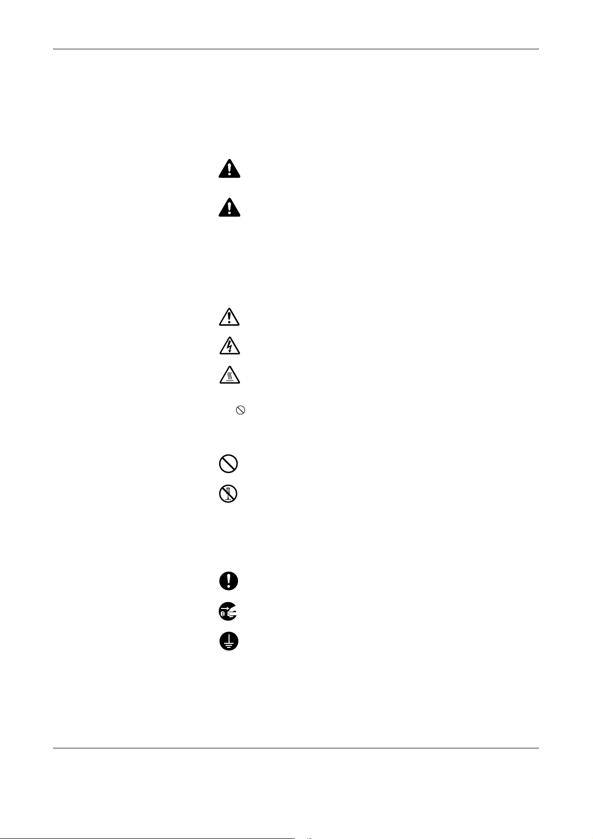
Symbols
The U symbol indicates that the related section includes safety warnings.
Specific points of attention are indicated inside the symbol.
.... [General warning]
Legal and Safety Information
.... [Warning of danger of electrical shock]
.... [Warning of high temperature]
The symbol indicates that the related section includes information on
prohibited actions. Specifics of the prohibited action are indicated inside
the symbol.
.... [Warning of prohibited action]
.... [Disassembly prohibited]
The z symbol indicates that the related section includes information on
actions which must be performed. Specifics of the required action are
indicated inside the symbol.
.... [Alert of required action]
.... [Remove the power plug from the outlet]
[Always connect the machine to an outlet with a ground
....
connection]
Please contact your service representative to order a replacement if the
safety warnings in this Operation Guide are illegible or if the guide itself is
missing (fee required).
OPERATION GUIDE ix
Page 12
Legal and Safety Information
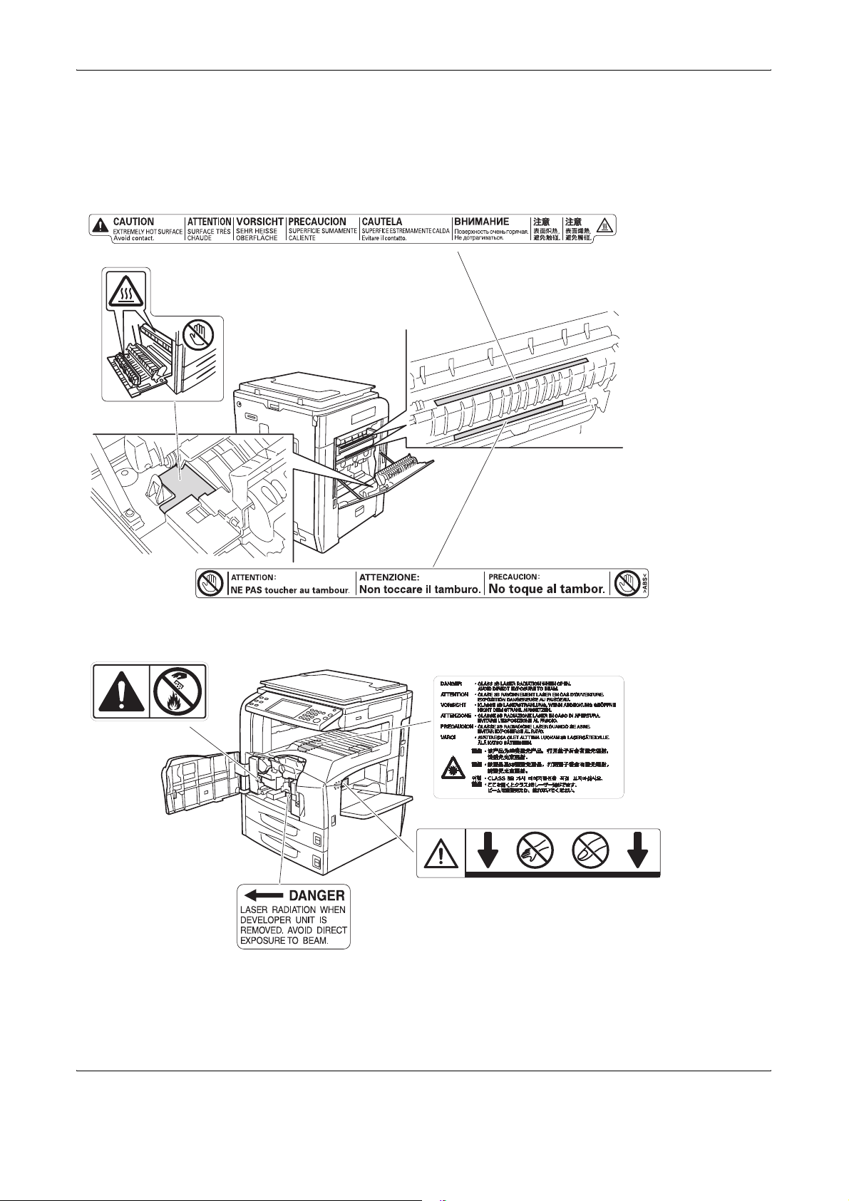
Caution / Warning Labels
Caution / Warning labels have been attached to the machine at the
following locations for safety purposes. Be sufficiently careful to avoid fire
or electric shock when removing a paper jam or when replacing toner.
High temperature inside. Do not
touch parts in this area, because
there is a danger of getting burned.
Do not incinerate toner and toner container.
Dangerous sparks may cause burn.
High temperature inside. Do not
touch parts in this area, because
there is a danger of getting burned.
Label inside the machine (Laser
radiation warning)
Moving parts inside. May cause
personal injury. Do not touch
moving parts.
x OPERATION GUIDE
Page 13
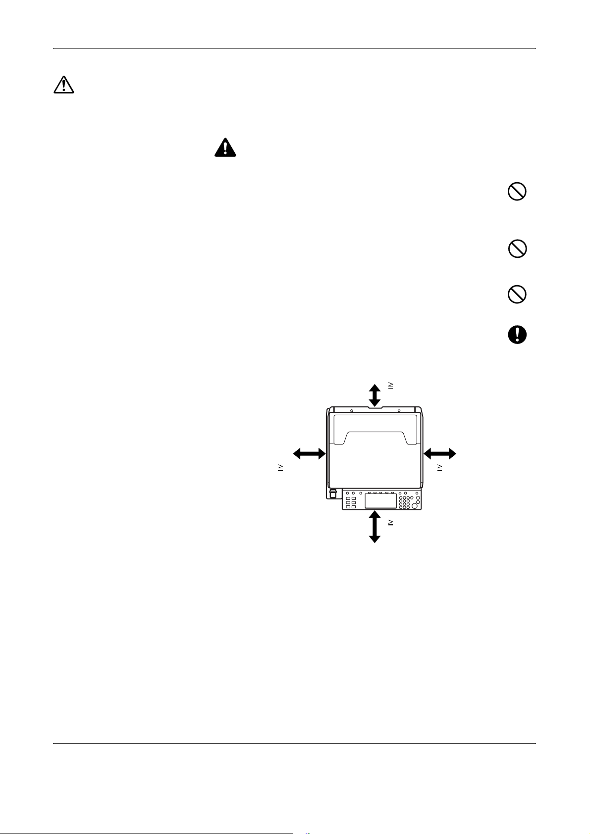
Installation Precautions
Environment
Avoid placing the machine on or in locations which are unstable
or not level. Such locations may cause the machine fall down or
fall over. This type of situation presents a danger of personal
injury or damage to the machine.
Avoid locations with humidity or dust and dirt. If dust or dirt
become attached to the power plug, clean the plug to avoid the
danger of fire or electrical shock.
Avoid locations near radiators, heaters or other heat sources, or
locations near flammable items to avoid the danger of fire.
To keep the machine cool and facilitate changing of parts and
maintenance, allow access space as shown below. Leave
adequate space, especially around the rear cover, to allow air to
be properly ventilated out of the machine.
Legal and Safety Information
CAUTION
Other precautions
3 15/16"
10 cm
11 13/16"
30 cm
39 3/8"
100 cm
Adverse environment conditions may affect the safe operation and
performance of the machine. Install in an air-conditioned room and avoid
the following locations when selecting a site for the machine.
• Avoid locations near a window or with exposure to direct sunlight.
• Avoid locations with vibrations.
• Avoid locations with drastic temperature fluctuations.
• Avoid locations with direct exposure to hot or cold air.
• Avoid poorly ventilated locations.
11 13/16"
30 cm
OPERATION GUIDE xi
Page 14

Legal and Safety Information
Power supply/Grounding the machine
If the floor is delicate against casters, when this machine is moved after
installation, the floor material may be damaged.
During copying, some ozone is released, but the amount does not cause
any ill effect to one’s health. If, however, the machine is used over a long
period of time in a poorly ventilated room or when making an extremely
large number of copies, the smell may become unpleasant. To maintain
the appropriate environment for copy work, it is suggested that the room
be properly ventilated.
WARNING
Do not use a power supply with a voltage other than that
specified. Avoid multiple connections in the same outlet. These
types of situations present a danger of fire or electrical shock.
Plug the power cord securely into the outlet. If metallic objects
come into contact with the prongs on the plug, it may cause a fire
or electric shock.
Always connect the machine to an outlet with a ground
connection to avoid the danger of fire or electrical shock in case
of an electric short. If an earth connection is not possible, contact
your service representative.
Other precautions
Connect the power plug to the closest outlet possible to the machine.
Handling of plastic bags
Keep the plastic bags that are used with the machine away from
children. The plastic may cling to their nose and mouth causing
suffocation.
WARNING
xii OPERATION GUIDE
Page 15

Precautions for Use
Cautions when using the machine
Do not place metallic objects or containers with water (flower
vases, flower pots, cups, etc.) on or near the machine. This type
of situation presents a danger of fire or electrical shock should
they fall inside.
Do not remove any of the covers from the machine as there is a
danger of electrical shock from high voltage parts inside the
machine.
Do not damage, break or attempt to repair the power cord. Do not
place heavy objects on the cord, pull it unnecessarily or cause
any other type of damage. These types of situations present a
danger of fire or electrical shock.
Legal and Safety Information
WARNING
Never attempt to repair or disassemble the machine or its parts
as there is a danger of fire, electrical shock or exposure to the
laser. If the laser beam escapes, there is a danger of it causing
blindness.
If the machine becomes excessively hot, smoke appears from
the machine, there is an odd smell, or any other abnormal
situation occurs, there is a danger of fire or electrical shock. Turn
the main power switch off immediately, be absolutely certain to
remove the power plug from the outlet and then contact your
service representative.
If anything harmful (paper clips, water, other fluids, etc.) falls into
the machine, turn the main power switch off immediately. Next,
be absolutely certain to remove the power plug from the outlet to
avoid the danger of fire or electrical shock. Then contact your
service representative.
Do not remove or connect the power plug with wet hands, as
there is a danger of electrical shock.
Always contact your service representative for maintenance or
repair of internal parts.
OPERATION GUIDE xiii
Page 16

Legal and Safety Information
CAUTION
Do not pull the power cord when removing it from the outlet. If the
power cord is pulled, the wires may become broken and there is
a danger of fire or electrical shock. (Always grasp the power plu g
when removing the power cord from the outlet.)
Always remove the power plug from the outlet when moving the
machine. If the power cord is d ama ge d, the re is a d ang er o f fire
or electrical shock.
Always hold the designated parts only when lifting or moving the
machine.
For safety purposes, always remove the power plug from the
outlet when performing cleaning operations.
If dust accumulates within the machine, there is a danger of fire
or other trouble. It is therefore recommended that you consult
with your service representative in regard to cleaning of internal
parts. This is particularly effective if accomplished prior to
seasons of high humidity. Consult with your servic e
representative in regard to the cost of cleaning the internal parts of the
machine.
Other precautions
Do not place heavy objects on the machine or cause other damage to the
machine.
Do not open the front cover , turn of f the ma in power switch, or pull out th e
power plug during copying.
When lifting or moving the machine, contact your service representative.
Do not touch electrical parts, such as connectors or printed circuit boards.
They could be damaged by static electricity.
Do not attempt to perform any operations not explained in this guide.
Caution: Use of controls or adjustments or performance of procedures
other than those specified herein may result in hazardous radiation
exposure.
Do not look directly at the light from the scanning lamp as it may cause your
eyes to feel tired or painful.
This machine comes equipped with an HDD (hard disk drive). Do not
attempt to move the machine while the power is still on. Since any resulting
shock or vibration may cause damage to the hard disk, b e sure to turn off
the power before attempting to move the machine.
xiv OPERATION GUIDE
Page 17

In the event there is a problem with the machine’s HDD (hard disk drive),
stored data may be erased. It is recommended that important data be
backed up on a PC or other media. Be also sure to store originals of
important documents separately.
If using the optional Data Backup Kit, received fax data on the HDD can be
stored here and prevent accidental loss of data.
Cautions when handling consumables
CAUTION
Do not attempt to incinerate the toner container or the waste
toner box. Dangerous sparks may cause burns.
Keep the toner container and the waste toner box out of the
reach of children.
If toner happens to spill from the toner container or the waste
toner box, avoid inhalation and ingestion, as well as contact with
your eyes and skin.
Legal and Safety Information
Other precautions
• If you do happen to inhale toner, move to a place with fresh
air and gargle thoroughly with a large amount of water. If coughing
develops, contact a physician.
• If you do happen to ingest toner, rinse your mouth with water and drink
1 or 2 cups of water to dilute the contents of your stomach. If
necessary, contact a physician.
• If you do happen to get toner in your eyes, flush them thoroughly with
water. If there is any remaining tenderness, contact a physician.
• If toner does happen to get on your skin, wash with soap and water.
Do not attempt to force open or destroy the toner container or the
waste toner box.
If the optional Fax kit is installed and the main power switch is off,
transmitting/receiving Fax is disabled. Do not turn off the main power
switch, but press the Power key on the operation panel to enter Sleep
mode.
Return the exhausted toner container and waste toner box to your dealer
or service representative. The collected toner container and waste toner
box will be recycled or disposed in accordance with the relevant
regulations.
Store the machine while avoiding exposure to direct sunlight.
OPERATION GUIDE xv
Page 18

Legal and Safety Information
Store the machine in a place where the temperature stays below 40ºC
while avoiding sharp changes of temperature and humidity.
If the machine will not be used for an extended period of time, remove the
paper from the cassette and the Multi Purpose (MP) Tray, return it to its
original package and reseal it.
xvi OPERATION GUIDE
Page 19
SAFETY OF LASER BEAM
1. Safety of laser beam
This machine has been certified by the manufacturer to Class 1 level
under the radiation performance standards established by the
U.S.DHHS (Department of Health and Human Services) in 1968. This
indicates that the product is safe to use during normal operation and
maintenance. The laser optical system, enclosed in a protective
housing and sealed within the external covers, never permits the
laser beam to escape.
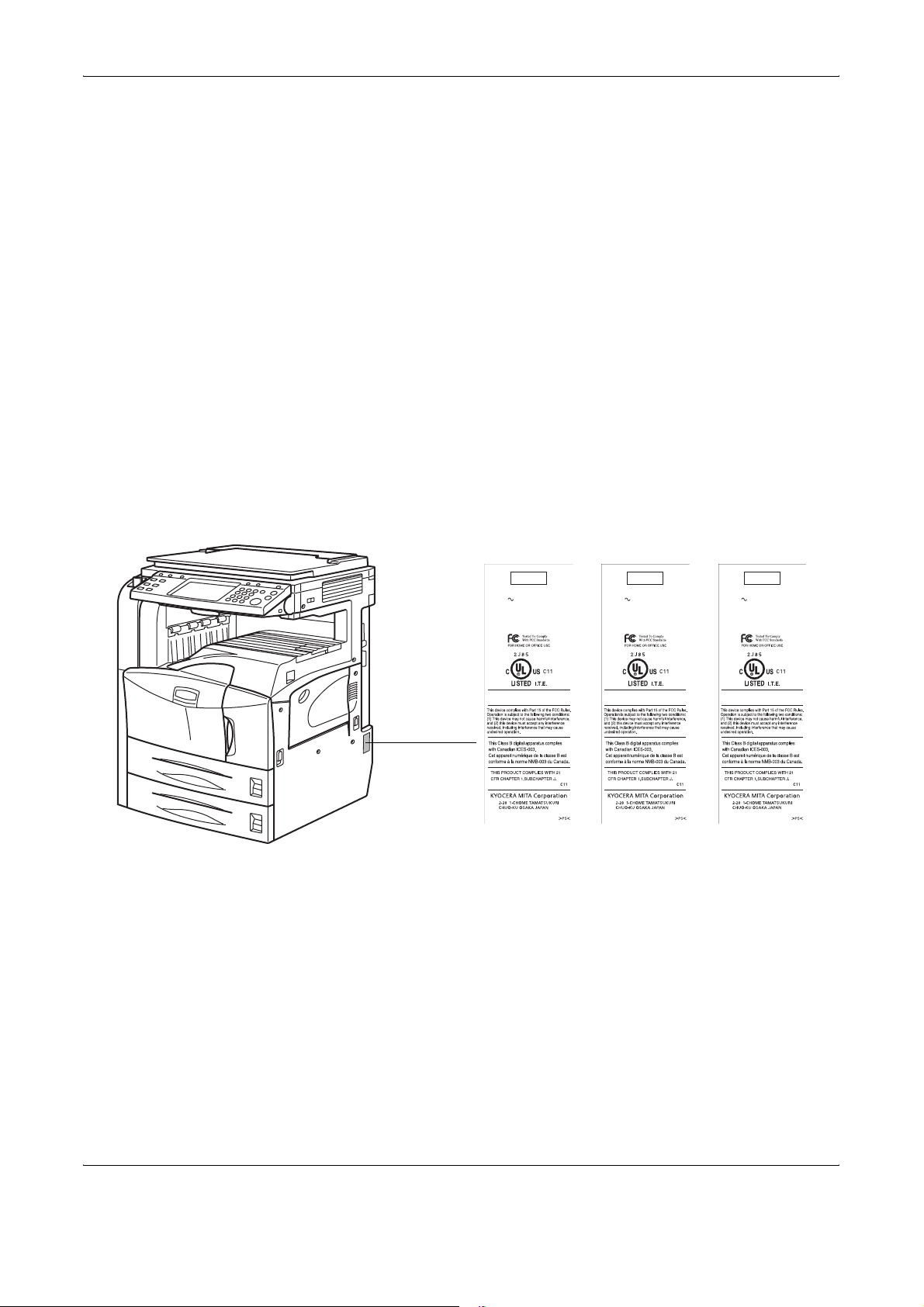
2. The CDRH Act
A laser-product-related act was implemented on Aug. 2, 1976, by the
Center for Devices and Radiological Health (CDRH) of the U.S. Food and
Drug Administration (FDA). This act prohibits the sale of laser products in
the U.S. without certification, and applies to laser products manufactured
after Aug. 1, 1976. The label shown below indicates compliance with the
CDRH regulations and must be attached to laser products marketed in the
United States. On this machine, the label is on the right.
Legal and Safety Information
3050
COPYING MACHINE
120V 60Hz 11.5A
MACHINE
No.PPH
MANUFACTURED
FCC ID:E52B5J0151
Contains IC:1059B-B5J0151
MADE IN CHINA
4050
COPYING MACHINE
120V 60Hz 11.5A
MACHINE
No.PPJ
MANUFACTURED
FCC ID:E52B5J0151
Contains IC:1059B-B5J0151
MADE IN CHINA
5050
COPYING MACHINE
120V 60Hz 11.5A
MACHINE
No.PPK
MANUFACTURED
FCC ID:E52B5J0151
Contains IC:1059B-B5J0151
MADE IN CHINA
OPERATION GUIDE xvii
Page 20
Legal and Safety Information
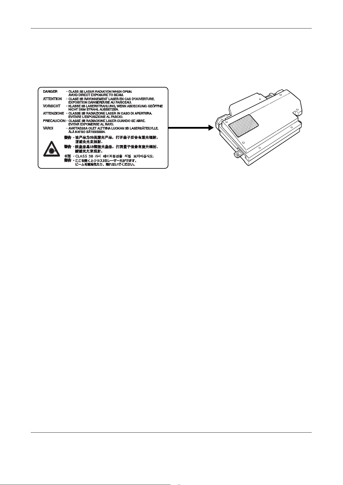
3. Optical unit
4. Maintenance
When checking the optical unit, avoid direct exposure to the laser beam,
which is invisible. Shown at below is the label located on the cover of the
optical unit.
5. Safety switch
For safety of the service personnel, follow the maintenance instructions in
the other section of this manual.
The power to the laser unit is cut off when the front cover is opened.
xviii OPERATION GUIDE
Page 21

Legal and Safety Information
Safety Instructions Regarding the Disconnection of Power
Caution: The power plug is the main isolation device! Other switches on
the equipment are only functional switches and are not suitable for
isolating the equipment from the power source.
Attention: Le débranchement de la fiche secteur est le seul moyen de
mettre l’appareil hors tension. Les interrupteurs sur l’appareil ne sont que
des interrupteurs de fonctionnement: ils ne mettent pas l’appareil hors
tension.
WARNING
This equipment has been tested and found to comply with the limits for a Class B digital device, pursuant to Part 15 of the
FCC Rules. These limits are designed to provide reasonable protection against harmful interference in a residential
installation. This equipment generates, uses and can radiate radio frequency energy and, if not installed and used in
accordance with the instructions, may cause harmful interference to radio communications. However, there is no
guarantee that interference will not occur in a particular installation. If this equipment does cause harmful interference to
radio or television reception, which can be determined by turning the equipment off and on, the user is encouraged to try
to correct the interference by one or more of the following measures:
• Reorient or relocate the receiving antenna.
• Increase the separation between the equipment and receiver.
• Connect the equipment into an outlet on a circuit different from that to which the receiver is connected.
• Consult the dealer or an experienced radio/TV technician for help.
• The use of a non-shielded interface cable with the referenced device is prohibited.
CAUTION — The changes or modifications not expressly approved by the party responsible for compliance could void the
user’s authority to operate the equipment.
This device complies with Part 15 of FCC Rules and RSS-Gen of IC Rules.
Operation is subject to the following two conditions; (1) this device may not cause interference, and (2) this device must
accept any interference, including interference that may cause undesired operation of the device.
* The above warning is valid only in the United States of America.
Radio Tag Technology
In some countries the radio tag technology used in this equipment to identify the toner container may be subject to
authorization and the use of this equipment may consequently be restricted.
MERCURY WARNING
THE LAMP(S) INSIDE THIS PRODUCT CONTAIN MERCURY AND MUST BE RECYCLED OR DISPOSED OF
ACCORDING TO LOCAL, STATE OR FEDERAL LAWS.
Other precautions (for users in California, the United States)
This product contains a CR Coin Lithium Battery which contains Perchlorate Material - special handling may
apply. See www.dtsc.ca.gov/hazardouswaste/perchlorate
.
OPERATION GUIDE xix
Page 22

Legal and Safety Information
Warranty
NEW 3050/4050/5050 MULTIFUNCTIONAL PRODUCT LIMITED
WARRANTY
1. Kyocera Mita America, Inc. and Kyocera Mita Canada, Ltd. (both referred to as “Kyocera”)
warrant the Customer's new Multifunctional Product (referred to as “MFP”), and the new
accessories installed with the initial installation of the MFP, against any defects in material and
workmanship as follows. For model KM-3050 - one year from date of installation or
400,000copies/prints, whichever occurs first; and for models KM-4050 and KM-5050 - one year
from date of installation or 500,000 copies/prints,, whichever occurs first. In the event the MFP
or an accessory is found to be defective within the warranty period, Kyocera's only obligation
and the Customer's exclusive remedy shall be replacement of any defective parts. Kyocera shall
have no obligation to furnish labor.
2. This warranty is valid only for the original retail purchaser (referred to as the “Customer”) of a
new Kyocera MFP in the United States of America or Canada, based upon the country of
purchase.
3. In order to obtain performance of this warranty, the Customer must immediately notify the Authorized
Kyocera Dealer from whom the product was purchased. If the Kyocera Dealer is not able to provide
service, write to Kyocera at the address below for the name and address of the Authorized Kyocera
Dealer in your area, or check Kyocera’s Website at www.kyoceramita.com
./us.
4. This warranty does not cover MFP's or accessories which: (a) have become damaged due to
operator negligence, misuse, accidents, improper storage or unusual physical or electrical
stress, (b) have used parts or supplies which are not genuine Kyocera brand parts or supplies,
(c) have been serviced by a technician not employed by Kyocera or an Authorized Kyocera
Dealer, or (d) have had the serial number modified, altered, or removed.
5. This warranty does not cover Maintenance Kits or the components of Maintenance Kits, which
consist of the drum unit, the fixing unit, and the developing unit which have a separate warranty.
6. This warranty gives the Customer specific legal rights. The Customer may also have other
rights, which vary from state to state, or province to province. Neither the seller, nor any other
person, is authorized to extend the time period, or expand this warranty on behalf of Kyocera.
7. THIS WARRANTY IS MADE IN LIEU OF ALL OTHER WARRANTIES AND CONDITIONS,
EXPRESS OR IMPLIED, AND KYOCERA SPECIFICALLY DISCLAIMS ANY IMPLIED
WARRANTY OR CONDITION OF MERCHANTABILITY OR FITNESS FOR A PARTICULAR
PURPOSE. THIS WARRANTY SHALL NOT EXTEND TO, AND KYOCERA SHALL NOT BE
LIABLE FOR, ANY INCIDENTAL OR CONSEQUENTIAL DAMAGES WHICH MAY ARISE OUT
OF THE USE, OR INABILITY TO USE, THE MFP.
xx OPERATION GUIDE
Page 23

About this Operation Guide
This Operation Guide contains the following chapters.
Chapter 1 - Part Names
Identifies machine parts and operation panel keys.
Chapter 2 - Preparation before Use
Explains adding paper, placing originals, connecting the machine, and
necessary configurations before first use.
Chapter 3 - Basic Operation
Describes the procedures for basic copying, printing and scanning.
Chapter 4 - Optional Equipment
Introduces the convenient optional equipment available for this machine.
Chapter 5 - Maintenance
Describes cleaning and toner replacement.
Chapter 6 - Troubleshooting
Explains how to handle error messages, paper jams and other problems.
Appendix
Explains how to enter characters, and lists the machine specifications.
OPERATION GUIDE xxi
Page 24
About this Operation Guide
Included Guides
The following guides are supplied with the machine. Refer to them as
necessary.
Operation Guide (This Guide)
Describes how to load paper, basic copy, print and scan operations, and
troubleshooting.
Advanced Operation Guide
Explains copying, printing and scanning features in depth, as well as
default settings.
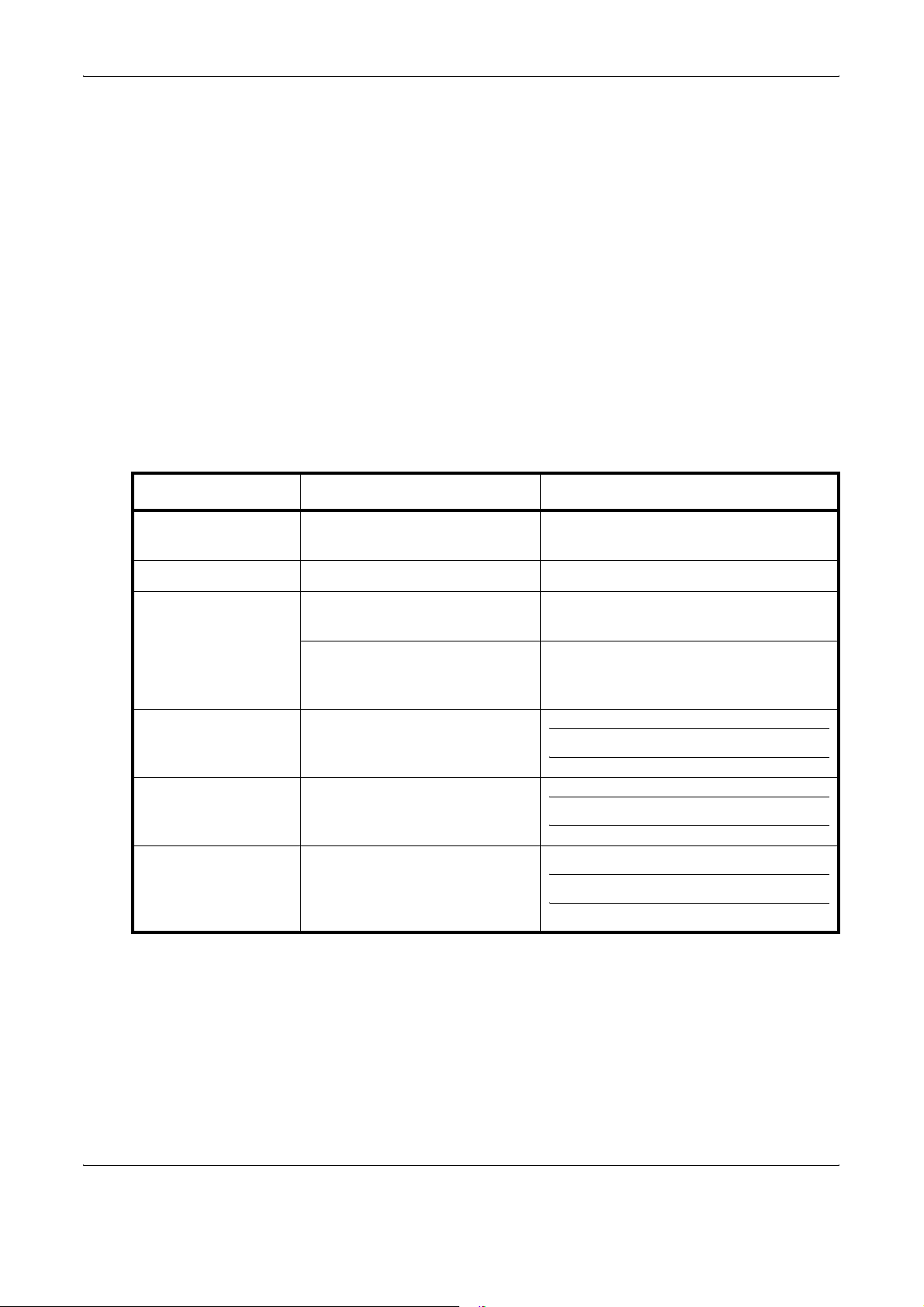
Conventions in This Guide
The following conventions are used depending on the nature of the
description.
Convention Description Example
Bold Indicates the operation panel
keys or a computer screen.
[Regular] Indicates the touch panel keys. Press [OK].
Italic Indicates a message displayed
on the touch panel.
Used to emphasize a key word,
phrase or references to
additional information.
Note Indicates supplemental
information or operations for
reference.
Important Indicates items that are required
or prohibited so as to avoid
problems.
Caution Indicates what must be
observed to prevent injury or
machine breakdown and how to
deal with it.
Press the Start key.
Ready to copy is displayed.
For more information refer to Sleep and
Auto Sleep on page 3-4.
NOTE:
IMPORTANT:
CAUTION:
xxii OPERATION GUIDE
Page 25

Description of Operation Procedure
In this Operation Guide, continuous operation of the keys on the touch
panel is as follows:
About this Operation Guide
Actual procedure
Press [Copy].
T
Press [Next] of Quick Setup.
T
Press [T] twice.
T
Press [Change] of Original Image.
Description in this
Operation Guide
Press [Copy], [Next] of Quick
Setup, [T] twice, and then
[Change] of Original Image.
OPERATION GUIDE xxiii
Page 26
About this Operation Guide
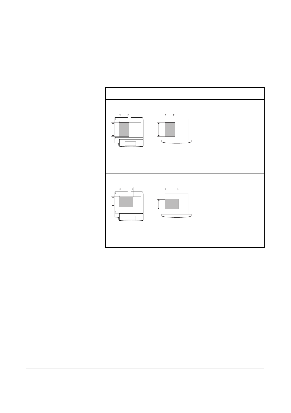
Originals and Paper Sizes
This section explains the notation used in this guide when referring to sizes
of originals or paper sizes.
As with A4, B5 and Letter, which may be used either in the horizontal or
vertical direction, horizontal direction is indicated by an additional letter R
in order to indicate the orientation of the original/paper.
Placement direction Indicated size *
Vertical direction A4, B5, A5, B6,
B B
A6, 16K, Letter,
Statement
A A
Original
Paper
For the originals/paper, dimension A is longer
than B.
Horizontal direction A4-R, B5-R, A5-R,
B B
B6-R, A6-R, 16KR, Letter-R,
Statement-R
A
Original
A
Paper
For the originals/paper, dimension A is shorter
than B.
* The size of the original/paper that can be used depends on the
function and source tray. For further details, refer to the page
detailing that function or source tray.
xxiv OPERATION GUIDE
Page 27

Icons on the Touch Panel
The following icons are used to indicate originals and paper placement
directions on the touch panel.
Placement direction Originals Paper
Vertical direction
Horizontal direction
About this Operation Guide
OPERATION GUIDE xxv
Page 28

About this Operation Guide
xxvi OPERATION GUIDE
Page 29

Contents
Legal and Safety Information . . . . . . . . . . . . . . . . . . . . . . . . . . . . . . . . . . . . . . . . . . . . . . . . . . . . . i
About this Operation Guide . . . . . . . . . . . . . . . . . . . . . . . . . . . . . . . . . . . . . . . . . . . . . . . . . . . . xxi
1Part Names
Machine . . . . . . . . . . . . . . . . . . . . . . . . . . . . . . . . . . . . . . . . . . . . . . . . . . . . . . . . . . . . . . . . . . . 1-2
Operation Panel . . . . . . . . . . . . . . . . . . . . . . . . . . . . . . . . . . . . . . . . . . . . . . . . . . . . . . . . . . . . . 1-5
2 Preparation before Use
Determining the Connection Method and Preparing Cables . . . . . . . . . . . . . . . . . . . . . . . . . . . 2-3
Connecting Cables . . . . . . . . . . . . . . . . . . . . . . . . . . . . . . . . . . . . . . . . . . . . . . . . . . . . . . . . . . . 2-5
Setting Date and Time . . . . . . . . . . . . . . . . . . . . . . . . . . . . . . . . . . . . . . . . . . . . . . . . . . . . . . . . 2-8
Configuring a Network (LAN Cable Connection) . . . . . . . . . . . . . . . . . . . . . . . . . . . . . . . . . . . 2-10
Accessing COMMAND CENTER (Settings for Network and Transmission) . . . . . . . . . . . . . . 2-12
TCP/IP Settings . . . . . . . . . . . . . . . . . . . . . . . . . . . . . . . . . . . . . . . . . . . . . . . . . . . . . . . . . . . . 2-13
Sending E-mail . . . . . . . . . . . . . . . . . . . . . . . . . . . . . . . . . . . . . . . . . . . . . . . . . . . . . . . . . . . . . 2-15
User Login Administration . . . . . . . . . . . . . . . . . . . . . . . . . . . . . . . . . . . . . . . . . . . . . . . . . . . . 2-27
Installing Software . . . . . . . . . . . . . . . . . . . . . . . . . . . . . . . . . . . . . . . . . . . . . . . . . . . . . . . . . . 2-30
Selecting the Default Screen . . . . . . . . . . . . . . . . . . . . . . . . . . . . . . . . . . . . . . . . . . . . . . . . . . 2-31
Changing Language . . . . . . . . . . . . . . . . . . . . . . . . . . . . . . . . . . . . . . . . . . . . . . . . . . . . . . . . . 2-33
Loading Paper . . . . . . . . . . . . . . . . . . . . . . . . . . . . . . . . . . . . . . . . . . . . . . . . . . . . . . . . . . . . . 2-34
Loading Originals . . . . . . . . . . . . . . . . . . . . . . . . . . . . . . . . . . . . . . . . . . . . . . . . . . . . . . . . . . . 2-46
Contents
3 Basic Operation
Power On/Off . . . . . . . . . . . . . . . . . . . . . . . . . . . . . . . . . . . . . . . . . . . . . . . . . . . . . . . . . . . . . . . 3-2
Sleep and Auto Sleep . . . . . . . . . . . . . . . . . . . . . . . . . . . . . . . . . . . . . . . . . . . . . . . . . . . . . . . . 3-4
Adjusting the Operation Panel Angle . . . . . . . . . . . . . . . . . . . . . . . . . . . . . . . . . . . . . . . . . . . . . 3-5
Touch Panel Display . . . . . . . . . . . . . . . . . . . . . . . . . . . . . . . . . . . . . . . . . . . . . . . . . . . . . . . . . . 3-6
Copying . . . . . . . . . . . . . . . . . . . . . . . . . . . . . . . . . . . . . . . . . . . . . . . . . . . . . . . . . . . . . . . . . . . 3-7
Printing - Printing from Applications . . . . . . . . . . . . . . . . . . . . . . . . . . . . . . . . . . . . . . . . . . . . . 3-22
Sending . . . . . . . . . . . . . . . . . . . . . . . . . . . . . . . . . . . . . . . . . . . . . . . . . . . . . . . . . . . . . . . . . . 3-24
Specifying Destination . . . . . . . . . . . . . . . . . . . . . . . . . . . . . . . . . . . . . . . . . . . . . . . . . . . . . . . 3-40
Using Document Box . . . . . . . . . . . . . . . . . . . . . . . . . . . . . . . . . . . . . . . . . . . . . . . . . . . . . . . . 3-43
Printing Documents Stored in Removable USB Memory . . . . . . . . . . . . . . . . . . . . . . . . . . . . . 3-54
Canceling/Viewing/Changing Jobs . . . . . . . . . . . . . . . . . . . . . . . . . . . . . . . . . . . . . . . . . . . . . . 3-56
Checking Remaining Toner and Paper . . . . . . . . . . . . . . . . . . . . . . . . . . . . . . . . . . . . . . . . . . 3-61
Quick Setup Screen . . . . . . . . . . . . . . . . . . . . . . . . . . . . . . . . . . . . . . . . . . . . . . . . . . . . . . . . . 3-62
4 Optional Equipment
Overview of Optional Equipment . . . . . . . . . . . . . . . . . . . . . . . . . . . . . . . . . . . . . . . . . . . . . . . . 4-2
Document Processor . . . . . . . . . . . . . . . . . . . . . . . . . . . . . . . . . . . . . . . . . . . . . . . . . . . . . . . . . 4-4
Paper Feeder . . . . . . . . . . . . . . . . . . . . . . . . . . . . . . . . . . . . . . . . . . . . . . . . . . . . . . . . . . . . . . . 4-4
3000 Sheet Paper Feeder . . . . . . . . . . . . . . . . . . . . . . . . . . . . . . . . . . . . . . . . . . . . . . . . . . . . . 4-5
Built-in Finisher . . . . . . . . . . . . . . . . . . . . . . . . . . . . . . . . . . . . . . . . . . . . . . . . . . . . . . . . . . . . . 4-5
Document Finisher . . . . . . . . . . . . . . . . . . . . . . . . . . . . . . . . . . . . . . . . . . . . . . . . . . . . . . . . . . . 4-9
3000 Sheet Document Finisher . . . . . . . . . . . . . . . . . . . . . . . . . . . . . . . . . . . . . . . . . . . . . . . . . 4-9
Job Separator . . . . . . . . . . . . . . . . . . . . . . . . . . . . . . . . . . . . . . . . . . . . . . . . . . . . . . . . . . . . . . 4-10
Document Table . . . . . . . . . . . . . . . . . . . . . . . . . . . . . . . . . . . . . . . . . . . . . . . . . . . . . . . . . . . . 4-10
Key Counter . . . . . . . . . . . . . . . . . . . . . . . . . . . . . . . . . . . . . . . . . . . . . . . . . . . . . . . . . . . . . . . 4-11
FAX Kit . . . . . . . . . . . . . . . . . . . . . . . . . . . . . . . . . . . . . . . . . . . . . . . . . . . . . . . . . . . . . . . . . . . 4-11
OPERATION GUIDE xxvii
Page 30

Contents
Data Backup Kit . . . . . . . . . . . . . . . . . . . . . . . . . . . . . . . . . . . . . . . . . . . . . . . . . . . . . . . . . . . . 4-11
Security Kit (USB Key) . . . . . . . . . . . . . . . . . . . . . . . . . . . . . . . . . . . . . . . . . . . . . . . . . . . . . . . 4-12
Serial Interface . . . . . . . . . . . . . . . . . . . . . . . . . . . . . . . . . . . . . . . . . . . . . . . . . . . . . . . . . . . . . 4-12
PDF Upgrade Kit (USB Key) . . . . . . . . . . . . . . . . . . . . . . . . . . . . . . . . . . . . . . . . . . . . . . . . . . 4-12
5 Maintenance
Cleaning . . . . . . . . . . . . . . . . . . . . . . . . . . . . . . . . . . . . . . . . . . . . . . . . . . . . . . . . . . . . . . . . . . . 5-2
Toner Container and Waste Toner Box Replacement . . . . . . . . . . . . . . . . . . . . . . . . . . . . . . . . 5-7
6 Troubleshooting
Solving Malfunctions . . . . . . . . . . . . . . . . . . . . . . . . . . . . . . . . . . . . . . . . . . . . . . . . . . . . . . . . . 6-2
Responding to Error Messages . . . . . . . . . . . . . . . . . . . . . . . . . . . . . . . . . . . . . . . . . . . . . . . . . 6-5
Clearing Paper Jams . . . . . . . . . . . . . . . . . . . . . . . . . . . . . . . . . . . . . . . . . . . . . . . . . . . . . . . . 6-12
Appendix . . . . . . . . . . . . . . . . . . . . . . . . . . . . . . . . . . . . . . . . . . . . . . . . . . . . . . . . . . . .Appendix-1
Character Entry Method . . . . . . . . . . . . . . . . . . . . . . . . . . . . . . . . . . . . . . . . . . . . . . . . .Appendix-2
Specifications . . . . . . . . . . . . . . . . . . . . . . . . . . . . . . . . . . . . . . . . . . . . . . . . . . . . . . . . .Appendix-6
Index . . . . . . . . . . . . . . . . . . . . . . . . . . . . . . . . . . . . . . . . . . . . . . . . . . . . . . . . . . . . . . . . . .Index-1
xxviii OPERATION GUIDE
Page 31

2 Preparation before Use
This chapter explains the preparations before using this
equipment for the first time as well as the procedures for
loading papers and originals.
•
Determining the Connection Method and Preparing Cables
• Connecting Cables....................................................... 2-5
• Setting Date and Time.................................................. 2-8
• Configuring a Network (LAN Cable Connection)........ 2-10
• Accessing COMMAND CENTER (Settings for Network
and Transmission)...................................................... 2-12
• TCP/IP Settings.......................................................... 2-13
• Sending E-mail........................................................... 2-15
• User Login Administration .......................................... 2-27
...... 2-3
• Installing Software...................................................... 2-30
• Selecting the Default Screen...................................... 2-31
• Changing Language ................................................... 2-33
• Loading Paper............................................................ 2-34
• Loading Originals ....................................................... 2-46
OPERATION GUIDE 2-1
Page 32

Preparation before Use
Check bundled items
Documents Contained in the Included CD-ROM
Check that the following items have been bundled.
• Operation Guide (This Guide)
• CD-ROM(Product Library)
• CD-ROM(TWAIN compatible application)
The following documents are contained in the included CD-ROM (Product
Library). Refer to them as necessary.
Documents
Advanced Operation Guide
KX Driver User Guide
Network FAX Driver Operation Guide
COMMAND CENTER Operation Guide
KM-NET for Clients Operation Guide
KM-NET for Direct Printing Operation Guide
Scan to SMB(PC) Setup Guide
PRESCRIBE Commands Technical Reference
PRESCRIBE Commands Command Reference
2-2 OPERATION GUIDE
Page 33

Determining the Connection Method and Preparing Cables
Check the method to connect the equipment to a PC or network, and
prepare the necessary cables.
Connection Example
Determine the method to connect the equipment to a PC or network by
referring to the illustration below.
Connecting a scanner to your PC network with a network
cable (100BASE-TX or 10BASE-T)
Preparation before Use
Administrator’s
PC
Printing
Network Fax
(Option)
COMMAND CENTER
Network settings, Scanner
default settings, User and
destination registration
Parallel
USB
Network
Network
MFP
Network
Network
Network
Send E-mail
Sends the image data
of scanned originals to
the desired recipient
as a file attached to an
E-mail message.
Send SMB
Saves the scanned
image as a data file on
your PC.
Send FTP
Sends the scanned
image as a data file on
the FTP.
Fax (Option)
Fax
Network
TWAIN Scanning
WIA Scanning
Network
TWAIN and WIA are
standardized interface
for communication
between software
applications and image
acquisition devices.
OPERATION GUIDE 2-3
Page 34

Preparation before Use
Preparing Necessary Cables
The following interfaces are available to connect the equipment to a PC.
Prepare the necessary cables according to the interface you use.
Available Standard Interfaces
Function Interface Necessary Cable
Printer/Scanner
/Network Fax*
Printer USB interface USB2.0 compatible cable
* Function available when using optional fax kit. For details on
Network Fax, refer to the Fax Kit Operation Guide.
Optional Interface
Serial interface is optionally available.
Function Interface Necessary Cable
Printer Serial interface RS-232C cable (Max. 15 m)
Network interface LAN (10Base-T or
100Base-TX, Shielded)
(Hi-Speed USB compliant,
Max. 5.0 m, Shielded)
Parallel interface Parallel cable (IEEE1284
Compliant, Max. 1.5 m)
2-4 OPERATION GUIDE
Page 35

Connecting Cables
Connecting LAN Cable (Optional)
Preparation before Use
Follow the steps below to connect a LAN cable to the machine.
When the machine is powered up, first press the Power key on the
1
operation panel. Check that the Power indicator and the memory indicator
are off. After this, turn off the main power switch.
Check that the
indicators are off.
Connect the LAN cable to the network interface located on right side of the
2
body.
Connect the other end of the cable to the hub.
3
Configure the network. For details, refer to Configuring a Network (LAN
4
Cable Connection) on page 2-10.
OPERATION GUIDE 2-5
Page 36

Preparation before Use
Connecting Parallel/USB Cable (Optional)
Follow the steps below to connect a parallel or USB printer cable to the
machine.
When the machine is powered up, first press the Power key on the
1
operation panel. Check that the Power indicator and the memory indicator
are off. After this, turn off the main power switch.
Check that the indicators
are off.
If connection is established using a parallel cable, the PC to be connected
2
should also be powered off.
Connect the printer cable to the appropriate interface located on the right
3
side of the body.
When Connecting to Parallel Interface
2-6 OPERATION GUIDE
Page 37

When Connecting to USB Interface
Connect the other end of the cable to the PC.
4
Connecting the Power Cable
Connect one end of the supplied power cable to the machine and the other
end to a power outlet.
Preparation before Use
IMPORTANT: Only use the power cable that comes with the machine.
OPERATION GUIDE 2-7
Page 38

Preparation before Use
Setting Date and Time
1
Follow the steps below to set the local date and time at the place of
installation.
When you send an E-mail using the transmission function, the date and
time as set here will be printed in the header of the E-mail message. Set
the date, time and time difference from GMT of the region where the
machine is used.
NOTE: Be sure to set the time difference before setting the date and
time.
Turn on the main power
switch.
Press the System Menu key.
2
Press [T], [Date/Timer] and then [Change] of Time Zone.
3
Select the region
4
and press [OK].
Date/Timer - Time Zone
Set time zone.
Pl ease sele ct the l ocati on n eares t you.
-12 :00 E niwe tok
-11 :00 Mi dwa y Is
-10 :00 H awa ii
-09 :00 Al aska
-08 :00 P fic Ti me
-07 :00 Ari zon a
Status 10/5/2006 10:10
Time Zone
1/13
Cance l O K
NOTE: Press [S] or [T] to view the next region.
2-8 OPERATION GUIDE
Page 39

Press [Change] of Date/Time.
5
Preparation before Use
Press [Off] or [On] of
6
Summer Time.
Set the date and
7
time. Press [+] or [–]
in each setting.
Date/Timer - Date /Time
Se t the da te an d tim e.
DMY
Summer Time
Off
SMH
On
Stat us 10/5/2006 10: 10
Date/Timer - Date /Time
Se t the da te an d tim e.
Stat us 10/5/2006 10: 10
Cance l OK
DMY
Summer Time
Off
SMH
On
Cance l OK
NOTE: Settings are Year (Y), Month (M), Date (D), Hour (H), Minute (M)
and Second (S).
Press [OK].
8
When exiting, press [Return to Top] repeatedly to return to the System
9
Menu default screen.
OPERATION GUIDE 2-9
Page 40

Preparation before Use
Configuring a Network (LAN Cable Connection)
The machine comes with a standard network interface and supports each
of TCP/IP, IPX/SPX, NetBEUI and AppleTalk protocols, allowing network
printing on various platforms such as Windows, Macintosh, UNIX and
NetWare.
Setting TCP/IP (When Using Fixed IP Address)
Follow the steps below to set TCP/IP when a fixed IP address is used.
Make sure that an IP address is available by asking your network
administrator to obtain it in advance.
Press the System Menu key.
1
Press [System], [Next] of Network and then [Change] of TCP/IP.
2
Press [On] of TCP/
3
IP.
Press [Off] of DHCP.
4
Press [IP Address]
5
and enter the IP
Syste m - TCP/IP
Use TCP /I P.
Off
On
Stat us 10/5/2006 10:10
Syste m - TCP/IP
Use TCP /I P.
DHCP
On
Off IP Address
Subnet Mask
Default
Gateway
address using the
numeric keys.
Off
On
DHCP
On
Off IP Address
Subnet Mask
Default
Gateway
0.0.0.0
0.0.0.0
0.0.0.0
Cance l OK
192.168.1.150
0.0.0.0
0.0.0.0
Stat us 10/5/2006 10:10
Cance l OK
2-10 OPERATION GUIDE
Page 41

Press [Subnet Mask] and enter the address using the numeric keys.
6
Press [Default Gateway] and enter the address using the numeric keys.
7
Check that all addresses are entered correctly, and press [OK].
8
Press the Power key, and after confirming that the Power key/indicator
9
and memory indicator have turned off, turn the main power switch off and
on.
Setting TCP/IP (When Using DHCP)
Follow the steps below to set TCP/IP when a DHCP server is available.
Press the System Menu key.
1
Preparation before Use
Press [System], [Next] of Network and then [Change] of TCP/IP.
2
Press [On] of TCP/
3
IP and [On] of
Syste m - TCP/IP
Use TCP /I P.
DHCP.
Off
On
Stat us 10/5/2006 10:10
Press [OK].
4
Press the Power key, and after confirming that the Power key/indicator
5
DHCP
On
Off IP Address
Subnet Mask
Default
Gateway
0.0.0.0
0.0.0.0
0.0.0.0
Cance l OK
and memory indicator have turned off, turn the main power switch off and
on.
OPERATION GUIDE 2-11
Page 42

Preparation before Use
Accessing COMMAND CENTER (Settings for Network and Transmission)
COMMAND CENTER is a tool used for tasks such as verifying the
operating status of the machine and changing the settings for security,
network printing, E-mail transmission and advanced networking.
NOTE: Here, information on the FAX settings has been omitted. For
more information on using the FAX, refer to the Fax Kit Operation Guide.
The procedure for accessing COMMAND CENTER is explained below.
Launch your Web browser.
1
In the Address or Location bar, enter the machine’s IP address.
2
E.g.) http://192.168.48.21/
The web page displays basic information about the machine and
COMMAND CENTER as well as their current status.
Select a category from the navigation bar on the left of the screen. The
3
values for each category must be set separately.
If restrictions have been set for COMMAND CENTER, enter the correct
user name and password to access pages other than the startup page.
2-12 OPERATION GUIDE
Page 43

TCP/IP Settings
Preparation before Use
Use this page to specify the settings required for network printing and
sending E-mail.
The procedure for specifying the TCP/IP settings is explained below.
Click Advanced -> Protocols -> TCP/IP -> General.
1
Enter the correct settings in each field.
2
OPERATION GUIDE 2-13
Page 44

Preparation before Use
The settings to be specified in the TCP/IP settings screen are explained
below.
Item Description
Host Name Specifies a name for the machine system network component. This name is also
used as the NetBEUI Printer Name and the SNMP sysName object.
IP Address Assigns the Internet Protocol address on the machine system network
component. The format of the IP Address is four-byte (32-bit) numbers separated
by dots, e.g. 192.168.48.21.
Subnet Mask Specifies the subnet mask configured on the machine system network
component. If the machine system does not automatically assign a usable default
value and the first number in the IP address is from 192 to 254, then use
255.255.255.0 as the subnet mask.
Default Gateway The IP address of the gateway router for the local network.
DHCP/BOOTP Identifies how the machine obtains its IP configuration: DHCP/BOOTP: automatic
configuration via a BOOTP server or a DHCP server.
RARP Automatic configuration using the Reverse Address Resolution Protocol.
DNS Server
(Primary, Secondary)
Domain Name The Domain Name System (DNS) to which the machine system belongs, such as
WINS Server
(Primary, Secondary)
Scope ID This section determines the scope of IP addresses that a Windows server can
FTP Status Check Enables or disables the FTP Status Check.
The IP address of the primary and secondary Domain Name System (DNS)
servers.
abcdnet.com. It should not include the host machine name.
The IP address of the primary and secondary Windows Internet Name Service
(WINS) servers.
grant or lease to any requesting network component. A DHCP server processes
the machine system’s discovery broadcasts and returns an IP address to it. The
DHCP server may be set up to grant an IP address for a limited time (a
temporary lease) or for an unlimited time (an unlimited lease), or it may be
configured with a permanent address reservation for the machine system.
Click Submit.
3
After completing the settings, restart the machine to save the settings.
4
2-14 OPERATION GUIDE
Page 45

Sending E-mail
Preparation before Use
Specifying the SMTP settings allows you to send images loaded onto this
machine as E-mail attachments.
To use this function, this machine must be connected to a mail server using
the SMTP protocol.
Before sending images loaded onto this machine as E-mail attachments,
check the following:
• The network environment used to connect this machine to the mail
server
A full-time connection via a LAN is recommended.
• SMTP Settings
Use COMMAND CENTER to register the IP address and host name
of the SMTP server.
• If limits have been set on the size of E-mail messages, it may not be
possible to send very large E-mails.
The procedure for specifying the SMTP settings is explained below.
Click Advanced -> SMTP -> General.
1
OPERATION GUIDE 2-15
Page 46

Preparation before Use
Item Description
Enter the correct settings in each field.
2
The settings to be specified in the SMTP settings screen are shown below.
SMTP Protocol Enables or disables SMTP protocol. To use E-mail, this protocol must be
enabled.
SMTP Port Number Set the SMTP Port Number or use the SMTP default port 25.
SMTP Server Name Enter the SMTP server IP address or its name. The maximum length of the
SMTP server name and IP address is 62 characters. If entering the name, a DNS
server address must also be configured. The DNS server address may be
entered on the TCP/IP General tab.
SMTP Server Timeout Enter the default time out for the server in seconds.
Authentication
Protocol
Authenticate as Authentication can be set from three POP3 accounts or you can choose a
Login User Name When Other is selected for Authenticate, the login user name set here will be
Login Password When Other is selected for Authenticate, the password set here will be used for
POP before SMTP
Timeout
Enables or disables the SMTP authentication protocol or sets POP before SMTP
as the protocol. The SMTP authentication supports Microsoft Exchange 2000.
different account.
used for SMTP authentication. The maximum length of the login user name is 62
characters.
authentication. The maximum length of the login password is 62 characters.
Enter the timeout (in seconds) if you chose POP before SMTP as the
Authentication Protocol.
Test This will test if the SMTP connection can be successfully established.
E-mail Size Limit Enter the maximum size of E-mail that can be sent in kilobytes. When the value is
0, the limitation for E-mail size is disabled.
2-16 OPERATION GUIDE
Page 47

Preparation before Use
Item Description
Sender Address Enter the E-mail address of the person responsible for the scanner system, such
as the machine administrator, so that a reply or non-delivery report will go to a
person rather than to the machine. The sender address must be entered
correctly for SMTP authentication. The maximum length of the sender address is
126 characters.
Signature Enter the signature. The signature is free form text that will appear at the end of
the E-mail body. It is often used for further identification of the machine. The
maximum length of the signature is 126 characters.
Domain Restriction Enter the domain names that can be permitted or rejected. The maximum length
of the domain name is 30 characters. You can also specify E-mail addresses.
Click Submit.
3
OPERATION GUIDE 2-17
Page 48

Preparation before Use
SMB Settings
The SMB function allows you to store scanned images on a computer
connected to the network.
To use this function, register the following information:
• Login User Name
• Login Password
• SMB Port Number (normally 139)
• The computer’s IP address and host name
• The computer path (to the destination folder to be used for the saved
images)
• Destination folder sharing (Writable shared folder)
The user name and password set using the operation panel are also used
to log on to the computer where the destination folder is located. Set the
access privileges for the folder in Windows on the computer where the
folder is located.
This section explains the procedure for specifying the SMB settings in
COMMAND CENTER.
Click Scanner -> SMB.
1
Enter the correct settings in each field.
2
The settings to be specified in the SMB settings screen are shown below.
Item Description
SMB Protocol Switches the SMB Protocol on or off.
SMB Port Number You can enter the port number to be used by SMB.
Click Submit.
3
2-18 OPERATION GUIDE
Page 49

FTP Settings
Preparation before Use
This function converts image files scanned using this machine to the PDF,
TIFF, or JPEG format and saves them before uploading them directly to
the FTP server.
To use this function, register the information below. If you are unsure about
this information, contact your system administrator.
• Login User Name
• Login Password
• FTP Port Number (normally 21)
• FTP server IP address and host name
• FTP path (to the destination folder to be used for the saved images)
• Sharing of the FTP server save destination (Writable shared folder)
The login user name and login password registered using the operation
panel are also used for FTP login. Set up and manage user accounts on
the FTP server.
This section explains the procedure for specifying the FTP settings in
COMMAND CENTER.
Click Scanner -> FTP.
1
Enter the correct settings in each field.
2
The settings to be specified in the FTP settings screen are shown below.
Item Description
FTP Switches FTP on or off.
FTP Port Number You can enter the port number to be used by FTP.
Click Submit.
3
OPERATION GUIDE 2-19
Page 50

Preparation before Use
Storing Information in the Address Book
You can use the machine’s operation panel to store E-mail addresses,
paths to folders (SMB) on a PC, the FTP server path and fax numbers in
the built-in Address Book.
You can also use COMMAND CENTER to add, edit and delete individual
contacts and group contacts in the Address Book.
Click Basic -> Address Book Contacts -> Add Contact.
1
Enter the correct settings in each field.
2
2-20 OPERATION GUIDE
Page 51

Preparation before Use
The settings to be specified in the Address Book Contacts settings screen
are shown below.
Item Description
Number Select the number of this address book.
Name Enter the registration name. The maximum length of the registration name is 32
characters.
E-Mail Address Enter the E-mail address.
Host Name SMB: Enter the IP address or host name of the destination.
FTP: Enter the FTP server IP address or its name.
The maximum length of the host name is 62 characters.
Path Enter the path of the required folder for uploading data. For example, to store
data in the ScannerData folder in the home directory, enter \ScannerData.
Login User Name SMB: Enter the login user name for the destination.
FTP: Enter the login user name for the FTP server.
The maximum length of the login user name is 62 characters.
Login Password SMB: Enter the login password for the destination.
FTP: Enter the login password for the FTP server.
The maximum length of the login user name is 62 characters.
Click Submit.
3
Editing Address Book Contacts
The procedure for editing information on the Address Book Contacts page
is explained below.
OPERATION GUIDE 2-21
Page 52

Preparation before Use
Click Basic -> Address Book Contacts -> Number or Name of the contact.
1
Modify the contact information.
2
Click Submit.
3
Adding a New Group
The procedure for adding a new group to the Address Book is explained
below.
2-22 OPERATION GUIDE
Page 53

Click Basic -> Address Book Groups -> Add Group.
1
Preparation before Use
Enter the correct settings in each field.
2
Enter the following settings in the Add Group screen.
Item Description
Number Enter the group number. You can enter any number between 1 and 2500.
If you enter a number that is already being used and click Submit, an error
message appears.
Group Name Enter the group name. The maximum length of the group name is 32 characters.
Click Submit.
3
OPERATION GUIDE 2-23
Page 54

Preparation before Use
Editing Groups
The procedure for editing groups in the Address Book is explained below.
Click Basic -> Address Book Groups -> Number or Name of the group to
1
be edited.
Click Add Members.
2
To delete a group member, tick the checkbox for the member to be deleted
and then click Delete Members.
2-24 OPERATION GUIDE
Page 55

Preparation before Use
Tick the checkbox for the member to be added to the group and then click
3
Submit.
The contact is added as a group member.
For each group, you can register up to a combined total of 10 SMB and
FTP addresses and up to 100 E-mail addresses.
Registering an External Address Book
This machine can refer to an address book on the LDAP server as an
external address book and store the fax number and E-mail address of the
destination.
Enable LDAP parameters in COMMAND CENTER.
The procedure for using an external address book is explained below.
Register an address book on the LDAP server. Refer to the Windows Help
1
menu for details.
OPERATION GUIDE 2-25
Page 56

Preparation before Use
In COMMAND CENTER, click Advanced -> Management > LDAP.
2
Enter the correct settings in each field.
3
The settings to be specified in the LDAP settings screen are shown below.
Item Description
LDAP Enables or disables access to the LDAP server.
LDAP Server Name Enter the LDAP server IP address or name. The maximum length of the LDAP
server name is 62 characters.
LDAP Port Number Enter the port number used by the LDAP server. Normally, 389 is used.
Search Timeout Enter the duration of LDAP server searches. You can enter any number between
5 and 60.
Login User Name Enter the user name used for LDAP logon. The maximum length of the login user
name is 62 characters.
Login Password Enter the password used for LDAP logon. The maximum length of the login
password is 62 characters.
Max Search Results Enter the maximum number of results displayed when the LDAP address book is
searched. You can enter any number between 4 and 30.
Search Base Specify the starting point for LDAP directory searches.
Display Mode Selects the default display mode from Display from the first name and Display
from the family name.
Click Submit.
4
2-26 OPERATION GUIDE
Page 57

User Login Administration
User login administration specifies how user access is administered on this
machine. Enter a correct login user name and password for user
authentication to log in.
Access privileges are in two types - User and Administrator. Certain items
in System Menu can be modified only by administrators.
Enabling/Disabling User Login Administration
Here, you can enable user login administration. Select one of the following
authentication methods:
Preparation before Use
Item Description
Local
Authentication
Network
Authentication
Press the System Menu key.
1
Press [User Login/Job Accounting].
2
If user login administration is invalid, the user authentication screen is
displayed. Enter a login user name and password, and press [Login]. By
default, the login user name and password are 5050 respectively.
User authentication based on user properties on the
local user list stored in the machine
User authentication based on Authentication
Server. Use user properties stored in Authentication
Server to access the network authentication login
page.
NOTE: The login user name and password are for default users with
administrator rights.
Press [Next] of User Login Setting and then [Change] of User Login.
3
OPERATION GUIDE 2-27
Page 58

Preparation before Use
Select [Local
4
Authentic.] or
[Network Authentic.]
to enable user login
administration.
Selecting [Off]
disables user login
administration.
If you select
[Network
Authentic.], enter
User Login/Job Accounting - User Login
Use r lo gi n a dmi ni stra tio n.
Pl ease sel ect au thenti cati on me thod .
Off
Loca l
Auth enti c.
Network
Auth enti c.
Stat us 10/5/2006 10:10
Host N ame
Domain Name
Server Type
NTLM
(WinNT)
Kerberos
(Win2000/2003)
Cance l
the host name (62
characters or less) and domain name (254 characters or less) for the
Authentication Server. Select [NTLM (WinNT)] or [Kerberos (Win2000/
2003)] as the authentication method.
NOTE: If the login user name and password are rejected, check the
following settings.
• Network Authentication setting of the machine
• User properties of the Authentication Server
• Clock time setting of the machine and the Authentication Server
OK
Login/Logout
5
Login
1
If you cannot login because of the setting of the machine, login as any
administrator registered in the local user list and correct the settings.
If the server type is [Kerberos (Win2000/2003)], only domain names
entered in uppercase will be recognized.
Press [OK].
If user login administration is enabled, it is necessary to enter the login user
name and password to use the machine.
If the screen shown
appears during
Enter login user name a nd password.
operations, press
[Login User Name].
Log in
Use r Na me
Log in
Password
abcdef
********
Stat us 10/5/2006 10:10
Enter the login user name and press [OK].
2
Log in
2-28 OPERATION GUIDE
Page 59

3
4
5
Logout
Preparation before Use
NOTE: For details on character entry, refer to Character Entry Method on
page 2 of the Appendix.
Press [Login Password].
Enter the password and press [OK].
Check the login user name and password are correct, and press [Login].
To logout from the machine, press the Logout key to return to the login
user name/password entry screen.
OPERATION GUIDE 2-29
Page 60

Preparation before Use
Installing Software
Install appropriate software on your PC from the included CD-ROM
(Product Library) if you want to use the printer function of this machine or
perform TWAIN / WIA transmission or FAX transmission from your PC.
NOTE: Installation on Windows XP, Windows NT 4.0/2000, Server 2003
and Windows Vista must be done by a user logged on with administrator
privileges.
Plug and Play is disabled on this device when in Sleep Mode. Wake the
device from Sleep Mode before continuing. See Sleep and Auto Sleep on
page 3-4.
2-30 OPERATION GUIDE
Page 61

Selecting the Default Screen
Select the default screen (on the touch panel) to appear following the
opening screen after power-on. The default screen is selectable from
among the following.
Preparation before Use
Default
screen
Copy Default screen for copying (screen to appear when
Send Default screen for sending (screen to appear when
Status Default screen for status/job cancel (screen to appear
Document Box Default screen for Document Box (screen to appear
Program Default screen for program (screen to appear when
Application Default screen for application (screen to appear when
Accessibility
Copy
Accessibility
Send
Screen appearing immediately after power-on.
the Copy key is pressed)
the Send key is pressed)
when the Status/Job Cancel key is pressed)
when the Document Box key is pressed)
the Program key is pressed)
the Application key is pressed)
Default screen for Accessibility Copy (screen to
appear when the Accessibility Display key is
pressed in the Copy screen)
Default screen for Accessibility Send (screen to
appear when the Accessibility Display key is
pressed in the Send screen)
Press the System Menu key.
1
Press [Common Settings] and then [Change] of Default Screen.
2
OPERATION GUIDE 2-31
Page 62

Preparation before Use
Select the desired
3
default screen.
Press [OK].
4
When exiting, press [Close] repeatedly to return to the System Menu
5
screen.
Com mon S ettin gs - De faul t Scree n
Set the default screen to be displ ayed when main power switch is turned on.
English
Application
Accessi bili ty
Copy
Stat us 10/5/2006 10: 10
Accessi bili ty
Send
Status Document Box ProgramSendCopy
Cance l OK
2-32 OPERATION GUIDE
Page 63

Changing Language
Preparation before Use
Follow the steps below to change the language to appear on the touch
panel.
Press the System Menu key.
1
Press [Common Settings] and then [Change] of Language.
2
Press the key for the
3
language you wish
to use.
Press [OK].
4
A message instructing you to turn the power off and on appears. Press
5
[OK].
Press the Power key on the operation panel. Check that the Power key
6
and the memory indicator are off. After this, turn on the main power switch
again.
The touch panel language will be changed.
Common Settings - Language
Set the language to use for the touch panel display.
English FrançaisDeutsch Italia no
NederlandsPortuguês
Status 10/5/2006 10:10
Español
Cance l OK
OPERATION GUIDE 2-33
Page 64

Preparation before Use
Loading Paper
Before Loading Paper
Paper can be loaded standardly in the two cassettes and the Multi Purpose
Tray. As options, 2 paper feeders and a side feeder of 3,000 sheets
capacity are also available (refer to Chapter 4 Options).
When you open a new package of paper, fan the sheets to separate them
slightly prior to loading in the following steps.
Bend the whole set of sheets to swell them in the middle.
1
Hold the stack at both ends and stretch it while keeping the entire stack
2
swelled.
Raise the right and left hands alternately to create a gap and feed air
3
between the papers.
Finally, align the papers on a level, flat table.
4
If the paper is curled or folded, straighten it before loading. Paper that is
curled or folded may cause a jam.
CAUTION: If you copy onto used paper (paper already used for copying),
do not use paper that is stapled or clipped together. This may damage the
machine or cause poor image quality.
NOTE: If printouts are curled or not neatly stapled, turn the stack in the
cassette upside down.
Avoid exposing opened paper to high temperatures and high humidity as
dampness can be a cause of problems. Seal any remaining paper after
loading in the Multi Purpose Tray or cassettes back in the paper storage
bag.
If the machine will not be used for a prolonged period, protect all paper
from humidity by removing it from the cassettes and sealing it in the paper
storage bag.
2-34 OPERATION GUIDE
Page 65

NOTE: If you use special paper such as letterhead, paper with holes or
paper with pre-prints like logo or company name, refer to the Advanced
Operation Guide.
Loading Paper in the Cassettes
Up to 500 sheets of standard paper (80 g/m2) or colored paper may be
loaded in each of the two standard cassettes.
The following paper sizes are supported: Ledger, Legal, Oficio II,
8.5×13.5", Letter, Letter-R, Statement-R, A3, B4, A4, A4-R, B5, B5-R,
A5-R, Folio, 8K, 16K, and 16K-R.
Pull the cassette out toward you until it stops.
1
NOTE: Do not pull out more than one cassette at a time.
Preparation before Use
Holding the paper width adjusting tab, move the paper width guides to fit
2
the paper.
NOTE: Paper sizes are marked on the cassette.
OPERATION GUIDE 2-35
Page 66

Preparation before Use
Using the paper length
3
adjusting tab, move the plate
to fit the paper.
NOTE: Paper sizes are
indicated on the cassettes.
To change between inch size
and metric size (A, B sizes),
follow the steps below to
adjust the size switch.
A
1. Holding the paper width
adjusting tab, move the
paper width guide to a
position other than that of
the paper.
2. Turn the size switch A 90°.
>
3. Move the size lever B up (C) or down (I).
C:metric size (centimeters) (A, B sizes)
I:inch size
4. Turn the size switch 90°to lock it. >
Align the paper flush against
4
the left side of the cassette.
B
2-36 OPERATION GUIDE
Page 67

Preparation before Use
IMPORTANT:
• Before loading the paper, be sure that it is not curled or folded. Paper
that is curled or folded may cause paper jams.
• Ensure that the loaded paper does not exceed the level indicator (see
illustration below).
• When loading the paper, keep the side that was closest the package
seal facing up.
• The paper length and width guides must be adjusted to the paper size.
Loading the paper without adjusting these guides may cause skewed
feeding and paper jams.
• Be sure that the paper length and width guides rest securely against
the paper. If there is a gap, readjust the guides to fit the paper.
Insert the appropriate paper
5
size card in the slot to indicate
the size of the paper inside.
Gently push the cassette back in.
6
NOTE: If the machine will not be used for a prolonged period, protect all
paper from humidity by removing it from the cassettes and sealing it in the
original package.
Select the media type (plain, recycled, etc.) loaded in the cassette. (Refer
7
to Selecting Paper Size and Media Type for the Cassettes on page 2-41).
Loading Paper in the Multi Purpose Tray
Up to 200 sheets of plain paper (80 g/m2) may be loaded in the Multi
Purpose Tray.
OPERATION GUIDE 2-37
Page 68

Preparation before Use
The Multi Purpose Tray accepts paper sizes from A3 to Hagaki and from
Ledger to Statement-R. Be sure to use the Multi Purpose Tray when you
print on any special paper.
The capacity of the Multi Purpose Tray is as follows.
• Thick paper (120 g/m
• Thick paper (160 g/m
• Thick paper (200 g/m
• Hagaki: 80 sheets
• OHP film: 25 sheets
• Envelope DL, Envelope C5, Comm. #10, Monarch, Youkei 4, Youkei 2
: 20 sheets
2
): 130 sheets
2
), Japanese noshi paper: 100 sheets
2
): 50 sheets
NOTE: When you load custom size paper, enter the paper size by
referring to Selecting Paper Size and Media Type for the Multi Purpose
Tray on page 2-43.
When you use special paper such as transparencies or thick paper, select
the media type by referring to Selecting Paper Size and Media Type for the
Multi Purpose Tray on page 2-43.
Open the Multi Purpose Tray.
1
Adjust the paper width guides
2
to the width of the paper.
2-38 OPERATION GUIDE
Page 69

3
Loading Envelopes
Preparation before Use
Insert the paper along the
paper width guides into the
tray until it stops.
IMPORTANT: Keep the side that was closest the package seal facing up.
Curled paper must be uncurled before use.
Straighten the top edge if it is curled.
Up to 20 envelopes may be loaded in the Multi Purpose Tray.
Acceptable envelope sizes are as follows.
Acceptable Envelope Size
Monarch 3 7/8"×7 1/2"
Comm. #10 4 1/8"×9 1/2"
Envelope DL 110×220 (mm)
Envelope C5 162×229 (mm)
Executive 7 1/4"×10 1/2"
Comm. #9 3 7/8"×8 7/8"
Comm. #6-3/4 3 5/8"×6 1/2"
ISO B5 176×250 (mm)
Envelope C4 229×324 (mm)
Oufuku Hagaki 200×148 (mm)
Youkei 2 Haguruma Envelope Swiss-You 2 w/o
border print WE-S2
Youkei 4 LIFE E506B (w/o border print) 234×105 (mm)
162×114 (mm)
OPERATION GUIDE 2-39
Page 70

Preparation before Use
Open the Multi Purpose Tray.
1
Adjust the paper width guides
2
to the width of the envelope.
For landscape form envelopes, close the flap. Insert the envelope all the
3
way along the width guides, keeping the printing side face-up and with the
flap closed.
For portrait form envelopes, open the flap. Insert the envelope all the way
along the width guides, keeping the printing side face-up and with the flap
positioned opposite to the entrance.
IMPORTANT: How to load envelopes (orientation and facing) will differ
depending on the type of envelope. Be sure to load it in correctly, otherwise
printing may be done in the wrong direction or on the wrong face.
NOTE: When you load envelopes in the Multi Purpose Tray, select the
envelope type by referring to Selecting Paper Size and Media Type for the
Multi Purpose Tray on page 2-43.
2-40 OPERATION GUIDE
Page 71

Selecting Paper Size and Media
Selecting Paper Size and Media Type for the Cassettes
When you use the cassettes 1 or 2 or the optional side feeder (cassettes 3
and 4), select the paper size and media type you load.
When you use the optional side feeder (cassette 3) of up to 3,000 sheets
capacity, select the media type only.
Selection Item Selectable Size/Type
Paper Size Auto Paper size is automatically detected and
Preparation before Use
selected. Select whether the paper is in
Metric size or in Inch size.
Media Type Plain, Vellum, Recycled, Preprinted, Bond,
Press the System Menu key.
1
Standard
Sizes 1
Standard
Sizes 2
Select from the standard sizes. Selectable
paper sizes are as follows.
Inch size: Ledger, Letter-R, Letter, Legal,
Statement-R, 8.5×13.5" and Oficio II
Metric size: A3, B4, A4, A4-R, B5, B5-R,
A5-R, and Folio
Select from the standard sizes not included
in Standard Sizes 1. Selectable paper sizes
are as follows.
Inch size: A3, B4, A4, A4-R, B5, B5-R, A5R, and Folio, 8K, 16K-R and 16K
Metric size: Ledger, Letter-R, Letter, Legal,
Statement-R, 8.5×13.5" and Oficio II, 8K,
16K-R and 16K
Color, Prepunched, Letterhead, High
Quality and Custom 1~8
Press [Common Settings], [Next] of Original/Paper Setup, [Next] of
2
Cassette setting.
In Cassette Settings, select one of [Cassette 1] to [Cassette 4] and press
3
[Next].
Then press Paper Size -> [Change].
OPERATION GUIDE 2-41
Page 72

Preparation before Use
NOTE: [Cassette 3] is only displayed when the optional cassette is
installed. Note also that the paper size is not displayed when the 3000
sheet feeder is used. Only the media type is displayed.
NOTE: [Cassette 4] is only displayed when the optional cassette (500-
sheet) is installed.
For automatic
4
detection of the
paper size, press
[Auto] and select
[Metric] or [Inch] as
the unit.
To select the paper
size, press
[Standard Sizes 1]
or [Standard Sizes
2] and select the
paper size.
Common Settings - Paper Size
Se t casse tte pa per si ze.
Auto
Standard
Sizes 1
Standard
Sizes 2
Stat us 10/5/2006 10:10
Commo n Settings - Custom 1
Se t casse tte pa per si ze.
Auto
Standard
Sizes 1
Standard
Sizes 2
Stat us 10/5/2006 10:10
Metri c
Led ge r Let ter
Statement 8.5x13.5" OficioII
Inch
Lette r Leg al
Cance l OK
Cance l OK
Press [OK]. The previous screen reappears.
5
Press [Change] of
6
Media Type and
select the media
type. Then press
[OK].
Common Settings - Me dia Type
Select type of paper in Cassette 1.
Plain
PreprintedRecycle d Bond
Lett erhe adPrepunched
Custom 2Custom 1
Custom 7Custom 6
Stat us 10/5/2006 10:10
Rough Vellum
Custom 3 Custom 4
Custom 8
Col or
High Quality
Custom 5
Cance l OK
2-42 OPERATION GUIDE
Page 73

Preparation before Use
Selecting Paper Size and Media Type for the Multi Purpose Tray
Select the paper size and media type when using the Multi Purpose Tray.
You can select in advance the paper size and media type that will be used
often.
Item Description
Paper
Size
Auto Paper size is automatically detected and
selected. Select whether the paper is in Metric
size or in Inch size.
Standard
Sizes 1
Standard
Sizes 2
Others Select from special standard sizes and custom
Select from the standard sizes. Selectable paper
sizes are as follows.
Inch size: Ledger, Letter-R, Letter, Legal,
Statement-R, Executive, 8.5×13.5", and Oficio II
Metric size: A3, A4-R, A4, A5-R, A6-R B4-R, B5R, B5, B6-R and Folio
Select from the standard sizes not included in
Standard Sizes 1. Selectable paper sizes are as
follows.
Inch size: A3, A4-R, A4, A5-R, A6-R B4-R, B5-R,
B5, B6-R and Folio, 8K, 16K-R and 16K
Metric size: Ledger, Letter-R, Letter, Legal,
Statement-R, Executive, 8.5×13.5", and Oficio II,
8K, 16K-R and 16K
sizes.
Selectable paper sizes are as follows.
ISO B5, Envelope #10, Envelope #9, Envelope
#6, Envelope Monarch, Envelope DL, Envelope
C5, Envelope C4, Hagaki, Oufuku Hagaki, Youkei
4, Youkei 2
Size
Entry
Media Type Selectable media types are as follows.
OPERATION GUIDE 2-43
Enter the size not included in the standard size.
Selectable paper sizes are as follows.
Inch size
X (Horizontal): 5.83~17" (in 0.01" increments),
Y (Vertical): 3.86~11.69" (in 0.01" increments)
Metric size
X (Horizontal): 148~432 mm (in 1mm
increments),
Y (Vertical): 98~297 mm (in 1mm increments)
Plain, Transparency, Vellum, Labels, Letterhead,
Recycled, Preprinted, Bond, Cardstock, Color,
Prepunched, Envelope, Thick, High Quality and
Custom 1~8
Page 74

Preparation before Use
Press the System Menu key.
1
Press [Common Settings], [Next] of Original/Paper Setup, [Next] of Multi
2
Purpose Tray Setting, and then [Change] of Paper Size.
For automatic detection of the paper size, press [Auto] and select [Metric]
3
or [Inch] as the unit.
To select the paper
size, press any of
[Standard Sizes 1],
[Standard Sizes 2],
[Others] or [Size
Entry] and select the
paper size.
If you have chosen
[Size Entry], press
[+] or [–] to enter X
(horizontal) and Y
(vertical) sizes. You
may enter the size
directly using the
numeric keys by
pressing [# Keys].
Common Settings - Multi Purpose Tray Setting
Se t the mu lti-p urpose tray pa per si ze.
Auto
Standard
Sizes 1
Standard
Sizes 2
Others
Size Entry
Stat us 10/5/2006 10:10Paper is remaining in Docum ent Proces sor.
Common Settings - Multi Purpose Tray Setting
Se t the mu lti-p urpose tray pa per si ze.
Auto
Standard
Sizes 1
Standard
Sizes 2
Others
Size Entry
Stat us 10/5/2006 10:10
Paper is remaining in Docum ent Proces sor.
Led ge r Letter Letter Leg al
Statement Executi ve 8.5x13.5" OficioII
Cance l OK
X(5.83 - 17.00)
Y(3.86 - 11.69)
17.00
11.69
"
# Keys
"
# Keys
Cance l O K
Press [OK]. The previous screen reappears.
4
2-44 OPERATION GUIDE
Page 75

Preparation before Use
Press [Change] of
5
Media Type and
select the media
type. Then press
[OK].
Common Settings - Me dia Type
Select type of paper in Multi-Purpose Tray.
Plain
Stat us 10/5/2006 10:10
Transparen cy Label s
PreprintedRecycle d Bond
Lett erhe adPrepunched
Custom 2Custom 1
Custom 7Custom 6
Rough Vellum
Cardsto ck
ThickEnvelope
Custom 3 Custom 4
Custom 8
Col or
High Quality
Custom 5
Cance l OK
OPERATION GUIDE 2-45
Page 76

Preparation before Use
Loading Originals
Placing Originals on the Platen
Follow the steps below to load originals for copying, sending or storing.
You may place books or magazines on the platen in addition to ordinary
sheet originals.
Open the original cover.
1
NOTE: If the optional document processor is installed, open the
document processor. Before opening the document processor, be sure
that there are no originals left on the original table or on the original eject
table. Originals left on the original table or on the original eject table may
fall off when the document processor is opened.
Keep the document processor open if the original is 40 mm or thicker.
Place the original. Put the
2
scanning side facedown and
align it flush against the
original size indicator plates
with the back left corner as the
reference point.
2-46 OPERATION GUIDE
Page 77

Original size indicator plates
(Inch models)
(Metric models)
Preparation before Use
Close the original cover.
3
IMPORTANT: Do not push the original cover forcefully when you close it.
Excessive pressure may crack the platen glass.
NOTE: Shadows may be produced around the edges and in the middle
of open-faced originals.
CAUTION: Do not leave the document processor open as there is a
danger of personal injury.
OPERATION GUIDE 2-47
Page 78

Preparation before Use
Loading Originals in the Document Processor
The optional document processor automatically scans each sheet of
multiple originals. Both sides of two-sided originals are scanned.
Part Names of the Document Processor
(6)
(3)
(1) Original table
(2) Original width guides
(3) Opening handle
(4) Original eject table
(5) Top cover
(6) Original placement indicator
Originals Supported by the Document Processor
The document processor supports the following types of originals.
Weight 45 g/m2 to 160 g/m
2
Size Maximum A3 to Minimum A5-R
Maximum Ledger to Minimum Statement-R
Capacity Plain paper (80 g/m
2
), High quality paper (50 g/m2),
Colored paper, Recycled paper: 100 sheets (Mixed sized
originals: 30 sheets)
Thick paper (120 g/m
Thick paper (160 g/m
2
): 66 sheets
2
): 50 sheets
Art paper, Coated paper: 1 sheet
High quality paper (110 g/m
2
(5)
): 73 sheets
(2) (1) (4)
Originals Not Supported by the Document Processor
Do not use the document processor for the following types of originals.
• Soft originals such as vinyl sheets
• Transparencies such as OHP film
• Carbon paper
• Originals with very slippery surfaces
• Originals with adhesive tape or glue
• Wet originals
2-48 OPERATION GUIDE
Page 79

• Originals with correction fluid which is not dried
• Irregularly shaped (non-rectangular) originals
• Originals with cut-out sections
• Crumpled paper
• Originals with folds (Straighten the folds before loading. Failure to do
so may cause the originals to jam).
• Originals bound with clips or staples (Remove the clips or staples and
straighten curls, wrinkles or creases before loading. Failure to do so
may cause the originals to jam).
How to Load Originals
IMPORTANT: Before loading originals, be sure that there are no originals
left on the original eject table. Originals left on the original eject table may
cause the new originals to jam.
Adjust the original width
1
guides to fit the originals.
Preparation before Use
Place the originals. Put the
2
side to be scanned (or the first
side of two-sided originals)
face-up. Slide the leading
edge into the document
processor as far as it will go.
The original placement
indicator will be lit.
IMPORTANT: Confirm that the original width guides exactly fit the
originals. If there is a gap, readjust the original width guides. The gap may
cause the originals to jam.
OPERATION GUIDE 2-49
Page 80

Preparation before Use
Original placement indicator
Ensure that loaded originals do not exceed the level indicator. Exceeding
the maximum level may cause the originals to jam (see the figure below).
Originals with punched holes or perforated lines should be placed in such
a way that the holes or perforations will be scanned last (not first).
The original placement
indicator is lit or unlit
depending on how originals
are placed.
Indications and their status are
as follows.
• Green (upper indicator) lit
: Original is placed
properly.
• Green (upper indicator)
blinking : Original is not placed properly. Remove and place again.
• Red (lower indicator) blinking : Original is jammed. Remove the
jammed original and place it properly.
2-50 OPERATION GUIDE
Page 81

1Part Names
This chapter identifies the machine parts and operation panel
keys.
• Machine........................................................................ 1-2
• Operation Panel ........................................................... 1-5
OPERATION GUIDE 1-1
Page 82

Part Names
Machine
1
3
2
4
5
6
7
8
1 Original Cover (Option)
2 Original Size Indicator Plates
3 Clip Holder
4 Receive Indicator … Blinks while data is received
9
10
11
12
5 Error Indicator… Blinks when an error occurs and a job is stopped
6 Left Cover 1
7 Left Cover 1 Lever
8 Left Cover 2
9 Platen
10 Operation Panel
11 Cassette 1
12 Cassette 2
1-2 OPERATION GUIDE
Page 83

Part Names
15
16 17
14
13
13 Toner Container Stopper
18
14 Toner Container
15 Waste Toner Box
16 Green Knob (A1)
17 Paper Feed Unit (A2)
18 Paper Feed Unit Cover (A3)
OPERATION GUIDE 1-3
Page 84

Part Names
19
29
30
31
20
21 22
19 USB Memory Slot (A1)
20 Front Cover
21 Paper Width Adjusting Tab
22 Length Adjustment Plate
28
32
23
24
25
26
33
34
35
36
27
23 Top Tray
24 Main Power Switch
25 Paper Width Guides
26 Multi Purpose (MP) Tray
27 Memory Card Cover Holder
28 Handles
29 USB Memory Slot (A2)
30 USB Memory Slot (A3)
31 Memory Card Slot
32 USB Interface Connector
33 Network Interface Connector
34 Parallel Interface Connector
35 Option Interface Slot (OPT1)
36 Option Interface Slot (OPT2)
1-4 OPERATION GUIDE
Page 85

Operation Panel
1
Part Names
12
5
9
10
11
13
14
15
181716
2
3
4
8
7
6
Ready t o copy.
Copy Ima ge
Set Original.
Original
:
- - -
Zoom
100%
:
Paper
- - -
:
Preview
Org./Paper/
Quick S etup La yout/Ed it Advance d
Status 10/5/2006 10:10
Norma l 0 Letter
Auto
Zoom Density Paper
1-sided
Text+Ph oto Colla te
>>1-sided
Duplex Original
Image
Image
Finishing
Quality
Copies
1
Plain
Selection
Collate/
Offset
Setup
19
20
21
22
23
1 System Menu Key/Indicator
2 Status/Job Cancel Key/Indicator
3 Program Key/Indicator
4 Application Key
5 Counter Key/Indicator
6 Copy Key/Indicator
7 Send Key/Indicator
8 Document Box Key/Indicator
9 Accessibility Display Key/Indicator
10 Print Indicator … Blinks during printing operation
11 Send Indicator … Blinks while data is transmitted
12 Receive Indicator … Blinks while data is received
13 Memory Indicator …Blinks while the machine is accessing the hard
disk, fax memory, Data Backup Kit (Option) or
USB memory (general-purpose item)
14 Error Indicator … Blinks when an error occurs and a job is stopped
15 Help Key/Indicator
16 Logout Key/Indicator
17 Power Key
18 Main Power Indicator
19 Numeric Keys
20 Clear Key
21 Start Key/Indicator
22 Stop Key
23 Reset Key
OPERATION GUIDE 1-5
Page 86

Part Names
1-6 OPERATION GUIDE
Page 87

3 Basic Operation
This chapter explains the following operations.
• Power On/Off................................................................ 3-2
• Sleep and Auto Sleep................................................... 3-4
• Adjusting the Operation Panel Angle ........................... 3-5
• Touch Panel Display..................................................... 3-6
• Copying ........................................................................ 3-7
• Printing - Printing from Applications ........................... 3-22
• Sending ...................................................................... 3-24
• Specifying Destination................................................ 3-40
• Using Document Box.................................................. 3-43
•
Printing Documents Stored in Removable USB Memory
• Canceling/Viewing/Changing Jobs............................. 3-56
....3-54
• Checking Remaining Toner and Paper....................... 3-61
• Quick Setup Screen ................................................... 3-62
OPERATION GUIDE 3-1
Page 88

Basic Operation
Power On/Off
Power On
Open the main power switch cover and turn the main power switch on.
Blinking/Lighting of each Key/Indicator
When turning on the main power switch, Key/Indicators such as Copy or
Send blink.
Power Off
Blinking: This function is in preparation. When each key is ready, the
indicator lights out one by one.
Unlit: This function is ready.
Lit: This function is selected. Copy is selected as the default so that
the Copy key/indicator lights on first.
NOTE: A key whose indicator is unlit can be used even if any other key
remains blinking.
If the optional Security Kit is installed, a message might display indicating
the security function is being activated and time may be taken to start up
when the power is turned on.
IMPORTANT: When turning off the main power switch, do not turn on the
main power switch again immediately. Wait more than 5 seconds, and then
turn on the main power switch.
Before turning off the main power switch, press the Power key on the
operation panel to off. Make sure that the Power key and the memory
indicator are off before turning off the main power switch.
CAUTION: Turning off the main power switch before pressing the Power
key to off may cause damage to the standard internal hard disk.
3-2 OPERATION GUIDE
Page 89

Basic Operation
Make sure that the indicators are off.
In case of not using the machine for an extended period of time
CAUTION: If the machine will not be used for several (overnight, etc.),
turn the main power switch off. If it will not be used for an extended period
of time (vacations, etc.), remove the power plug from the outlet for safety
purposes.
IMPORTANT: Do not turn the main power switch off when the optional fax
kit is installed. If you turn the main power switch off, you cannot receive fax
messages.
OPERATION GUIDE 3-3
Page 90

Basic Operation
Sleep and Auto Sleep
Sleep
To enter Sleep, press the Power key. All indicators on the touch panel will
go out to save power except the Main Power indicator. This status is
referred to as Sleep.
If print data is received during Sleep, the print job is performed while the
touch panel remains unlit.
When using the optional fax, received fax data is printed out while the
operation panel also remains unlit.
To resume, press the Power key. The machine will be ready to operate
within 15 seconds.
Auto Sleep
Auto Sleep automatically switches the machine into Sleep if left idle for a
preset time. The default preset time is 8 minutes.
3-4 OPERATION GUIDE
Page 91

Adjusting the Operation Panel Angle
Adjust the angle of the operation panel in two as shown by releasing the
operation panel lock lever.
Basic Operation
OPERATION GUIDE 3-5
Page 92

Basic Operation
Touch Panel Display
Display for Originals and Paper
The touch panel displays the selected paper source and output tray.
Size/orientation of
original and paper
Display when the Screen Changes
Ready to copy.
Copi es
1
Copy I ma ge
100% Normal 0 Auto
Original
Zoom
Paper
Stat us 10/5/2006 10:10
A4
:
Lette r
100%
:
:
A4
Lette r
Cha nge Se tting
Quick Setup
Zoom De nsity Original
1-si ded
>>1-sided
Duplex Original
Org./Paper/
Finishing
Text+Photo Coll ate
Image
Quality
The stand-by display (icon) may appear when the touch panel screen
changes.
Normal stand-by display
Original position
Interrupt
Output
tray
Paper
source
Size
Col late /
Offset
Layout/Ed itImage
Ready to copy.
Copy Ima ge
Set Original.
:
- - -
Original
100%
:
Zoom
:
Paper
- - -
Preview
Quick Setup
Status 10/5/2006 10:10
Rep eat
Copy
Org./Paper/
Finishing
Continuous
Scan
Job Finish
Notice
Advan ced
Setup
Auto I mage
Rota tion
Quality
Negative
Image
Priority
Ove rrid e
Layo ut/ Edi tImage
Copi es
Mi rror
Image
Multi-page
Form
Advan ced
Setup
1
Stand-by Display When System Menu Operation Is Completed
When the system
Ready to copy.
Copi es
menu operation is
completed and
Copy Ima ge
Interrupt
another function
(such as copying) is
Set Original.
Please wai t.
Processing data.
used, the display
shown appears.
:
Original
- - -
:
Zoom
100%
:
Send
- - -
Preview
Qui ck Setu p Layou t/Ed it Adva nced
Status 10/5/2006 10:10
Duplex Original
Org./Paper/
Finishing
Image
Quality
Image
Collate/
Offset
Setup
3-6 OPERATION GUIDE
1
Page 93

Copying
Basic Operation
Follow the steps as below for basic copying.
Press the Copy key when the
1
Copy key/indicator is off.
NOTE: If you place the original and press the Start key before the
machine has warmed up, only the scanning is performed in advance and
the copying job starts upon completion of the warm-up.
Place the originals on the
2
platen or in the optional
document processor.
NOTE: For loading instructions, refer to Loading Originals on page 2-46.
Check that [Auto] is selected of Paper Selection on the touch panel. Paper
3
that matches the size of the original will be selected automatically.
To change the paper
size, press [Org./
Paper/Finishing],
[Paper Selection]
and select the
desired paper
source.
Ready to copy.
Paper Selection
Press [OK] to display
the ima ge.
:
Original
- - -
:
Zoom
100%
:
Send
- - -
Status 10/5/2006 10:10
Add Shortcut Cancel OK
Auto
Lett er
Plain
Ledger
Plain
Lett er
Plain
Lett er
Plain
NOTE: Select paper size manually, if necessary, instead of using
automatic paper selection.
Lett er
Plain
MP Tra y
Se tting
Copi es
1
OPERATION GUIDE 3-7
Page 94

Basic Operation
Use the numeric keys to enter
4
the copy quantity. Specify the
desired number up to 999.
Press the Start key to start
5
copying.
Remove the finished copies
6
from the top tray.
Original Preview
1
You can display a preview image of the scanned document on the panel.
NOTE: To view a preview of an image stored in a Custom Box, refer to
the Advanced Operation Guide.
The procedure for previewing scanned originals is explained below.
The procedure described here is for copying a single-page original.
Place the original on the platen and press the Copy key.
3-8 OPERATION GUIDE
Page 95

Basic Operation
Press [Preview].
2
The machine starts
3
scanning the
original. When
scanning is
completed, the
preview image
appears on the
panel.
Ready to copy.
Copy Ima ge
Set Original.
Auto
Original
:
- - -
Zoom
100%
:
- - -
Paper
:
Preview
Quick Setup Layout/Edit Advanced
Status 10/5/2006 10:10
Zoom Density Paper
1-sided
>>1-sided
Duplex Original
Org./Paper/
Finishing
No rmal 0 Letter
Text+Photo Col late
Image
Image
Quality
Plain
Selection
Coll ate/
Offset
Ready to copy.
Copy Im age
100% Normal 0 Auto
Original
:
Lett er
Zoom
100%
:
Paper
:
Lette r
Cha nge S ettin g
Quick Setup
Stat us 10/5/2006 10:10
Zoom Density Origina l
1-sided
>>1-sided
Duplex Original
Org./Paper/
Finishing
Text+Photo Coll ate
Image
Quality
Size
Collate/
Offset
Layo ut/ Edi tImage
Copi es
Copi es
Advan ced
Interrupt
Setup
Interrupt
Setup
1
1
4
Adjusting Density
To change the quality or the layout, press [Change Setting]. Change the
settings and press [Preview] again to see a preview image with the new
settings.
NOTE: If you scan a multi-page original, only the first page is previewed.
If you are compiling multiple pages, first press [Preview], scan all the
originals, and then press [Scan finish], and a preview of the first page is
displayed.
To change the mode when a preview image is displayed, press Reset key
and then change the mode.
For booklet copying, the finished page including the lead page of the
original is displayed.
Preview is not available if a high compression PDF is selected.
Use this procedure to adjust the density when copying.
Density Adjustment
Option
Manual Adjust density using 7 or 13 levels.
Description
Auto Optimum density is selected according to the
density of the original.
The procedure for adjusting the density of copies is explained below.
OPERATION GUIDE 3-9
Page 96

Basic Operation
Set the original on
1
Ready to copy.
the platen and press
[Image Quality] ->
[Density].
Adjust density manually pressing [-3] (Lighter) to [+3] (Darker). You can
2
change the density level [-3] (Lighter) to [+3] (Darker) in half-steps.
To change density
adjustment from
Manual to Auto,
press [Auto].
Copy Ima ge
Density
Set Original.
Original
:
- - -
Zoom
100%
:
- - -
Paper
:
Preview
Quick Setup Layout/Edit Advanced
Status 10/5/2006 10:10
Org./Paper/
Finishing
Original
Image
Image
Quality
EcoPrint
Ready to copy.
Density
Auto
Press [OK] to displa y
the image.
Lig hte r No rma l Darke r
-3
-2. 5 -1 .5
-1
-2
0 +1 +2
-0.5 +0.5 +1.5 +2.5
Copi es
1
Setup
Copi es
1
+3
Press [OK].
3
Press the Start key. Copying begins.
4
Selecting Image Quality
Select image quality suited to the type of original.
Image Quality Option Description
Text+Photo For originals with both text and
Text For originals primarily consisting of text.
Photo For originals primarily consisting of
The procedure for selecting the quality of copies is explained below.
Status 10/5/2006 10:10
Cance l OKAdd S hortcut
photographs.
photographs.
3-10 OPERATION GUIDE
Page 97

Basic Operation
Set the original on
1
the platen and press
[Image Quality] ->
[Original Image].
Select the image
2
quality.
Ready to copy.
Copy Ima ge
Density
Set Original.
Original
:
- - -
Zoom
100%
:
- - -
Paper
:
Preview
Quick Setup Layout/Edit Advanced
Status 10/5/2006 10:10
Org./Paper/
Finishing
Original
Image
Image
Quality
EcoPrint
Ready to copy.
Original I mage
Select original document type
for best copy results.
Press [OK] to displa y
the image.
Status 10/5/2006 10:10
[Text + Photo]: Text and photos together.
[Text]: Only text, no photos.
[Photo]: Only photos, no text.
Text PhotoText+Photo
Add S hortcut
Cance l OK
Copi es
Setup
Copi es
1
1
Zoom Copying
Auto Zoom
Press [OK].
3
Press the Start key. Copying begins.
Adjust the magnification to reduce or enlarge the original image. The
following zoom options are available.
Automatically reduces or enlarges the original image suitably to the
selected paper size.
Ledger: 129 %
Letter-R
A3: 141 %
A4
Statement-R: 64 %
A5: 70 %
OPERATION GUIDE 3-11
Page 98

Basic Operation
Manual Zoom
Manually reduces or enlarges the original image in 1% increments
between 25% and 400%.
25 %
400 %
Preset Zoom
Reduces or enlarges at preset magnifications.
The following magnifications are available.
Model Zoom Level (OriginalCopy)
Inch Models 100%, Auto, 400% (Max.), 200% (STMT ->
Ledger), 154%(STMT -> Legal), 129% (Letter ->
Ledger), 121% (Legal -> Ledger), 78% (Legal ->
Letter), 77% (Ledger -> Legal), 64% (Ledger ->
Letter), 50% (Ledger -> STMT), 25% (Min.)
Metric Models 100%, Auto, 400% (Max.), 200% (A5 -> A3),
141% (A4 -> A3, A5 -> A4), 127% (Folio -> A3),
106% (11×15" -> A3), 90% (Folio -> A4), 75%
(11×15" -> A4),
70% (A3 -> A4, A4 -> A5), 50%, 25% (Min.)
Metric Models (Asia
Pacific)
100%, Auto, 400%, Max, 200% (A5 -> A3),
141% (A4 -> A3, B5 -> B4), 122% (A4 -> B4, A5
-> B5), 115% (B4 -> A3, B5 -> A4), 86% (A3 ->
B4, A4 -> B5), 81%(B4 -> A4, B5 -> A5), 70%
(A3 -> A4, B4 -> B5), 50%, 25% (Min.)
3-12 OPERATION GUIDE
Page 99

XY Zoom
Select vertical and horizontal magnifications individually. Reduce or
enlarge original images in 1% increments between 25% and 400%.
The procedure for using zoom copying is explained below.
Basic Operation
Y
X
Set the original on
1
the platen and press
[Layout/Edit] ->
[Zoom].
Press [Standard Zoom] to use Auto Zoom.
2
Ready to copy.
Copy I mage
Zoom Combine Margin/
Set Original.
Original
:
- - -
Zoom
100%
:
- - -
Paper
:
Preview
Qui ck Setu p Layo ut/Ed it Adva nced
Status 10/5/2006 10:10
Booklet Duplex Cover
Page # Memo Page
Org./Paper/
Finishing
Image
Quali ty
Cente ring
Press [+] or [–] to change the displayed magnification as desired. You can
also enter the magnification directly using the numeric keys by pressing [#
Keys].
When using Preset
Zoom, select the key
of desired
magnification.
When using XY
Zoom, press [XY
Zoom].
Press [+] or [–] to
change the
displayed
Ready to copy.
Zoom
Standard
Zoom
Press [OK] to disp lay
the ima ge.
Status 10/5/2006 10:10
XY Zoom
400%
200%
154%
129%
121%
Add S hortcut
Max.
STMT
>>Ledger
STMT
>>Legal
Lett er
>>Ledger
Leg al
>>Ledger
(25 - 400)
# Keys
100%
Auto
Cance l OK
magnifications of X
(horizontal) and Y (vertical). You can also enter the magnification directly
using the numeric keys by pressing [# Keys].
Copi es
Border Erase
Form
Overlay
Copi es
Leg al
78%
>>Letter
Led ge r
77%
>>Legal
Led ge r
64%
>>Letter
Led ge r
50%
>>STMT
Min .
25%
1
Setup
1
OPERATION GUIDE 3-13
Page 100

Basic Operation
3
4
Duplex Copying
One-sided to Two-sided
Press [Original
Orientation] to select
orientation of the
originals, either [Top
Edge Top] or [Top
Edge Left]. Then
press [OK].
Ready to copy.
Zoom
Press [OK] to disp lay
the ima ge.
Status 10/5/2006 10:10
Standard
Zoom
XY Zoom
X
Y (25 - 40 0)
Add S hortcut
(25 - 400)
# Keys
# Keys
Cance l OK
%
%
Copi es
Top Edge Top
Original
Orientation
Press [OK].
Press the Start key. Copying begins.
Produce two-sided copies. The following duplex options are available.
Produces two-sided copies from one-sided originals. In case of an odd
number of originals, the back side of the last copy will be blank.
1
5
4
3
2
1
2
5
3
4
1
Original Copy
The following binding options are available.
A Original Left/Right to Binding Left/Right: Images on the second sides
are not rotated.
B Original Left/Right to Binding Top: Images on the second sides are
rotated 180°. Copies can be bound on the top edge, facing the same
orientation when turning the pages.
3-14 OPERATION GUIDE
 Loading...