

Kyocera KM-3035, KM-4035, KM-5035 Service Manual

KM-3035
KM-4035
KM-5035
SERVICE
MANUAL
Published in April 2005
842FG112
Version 3.0

CAUTION
Danger of explosion if battery is incorrectly replaced. Replace only with the same or equivalent
type recommended by the manufacturer. Dispose of used batteries according to the
manufacturer’s instructions.
CAUTION
Double-pole/neutral fusing.

Version history
Version Date Replaced pages Remarks
1 19 October 2004 2-2-2 –
3.0 22 April 2005 Contents, 1-1-1, 1-1-2, 1-1-3, 1-1-4, 1-3-3, 1-3-4,
1-3-5, 1-3-6, 1-3-7, 1-3-7-1, 1-3-8,
Chapter 1-4 (overall rerised), 1-6-29, 1-6-30,
1-6-37, 1-6-41, 1-6-42, 2-4-15

This page is intentionally left blank.

Safety precautions
This booklet provides safety warnings and precautions for our service personnel to ensure the safety of
their customers, their machines as well as themselves during maintenance activities. Service personnel
are advised to read this booklet carefully to familiarize themselves with the warnings and precautions
described here before engaging in maintenance activities.
Safety warnings and precautions
Various symbols are used to protect our service personnel and customers from physical danger and
to prevent damage to their property. These symbols are described below:
DANGER: High risk of serious bodily injury or death may result from insufficient attention to or incorrect
compliance with warning messages using this symbol.
WARNING:Serious bodily injury or death may result from insufficient attention to or incorrect compliance
with warning messages using this symbol.
CAUTION:Bodily injury or damage to property may result from insufficient attention to or incorrect
compliance with warning messages using this symbol.
Symbols
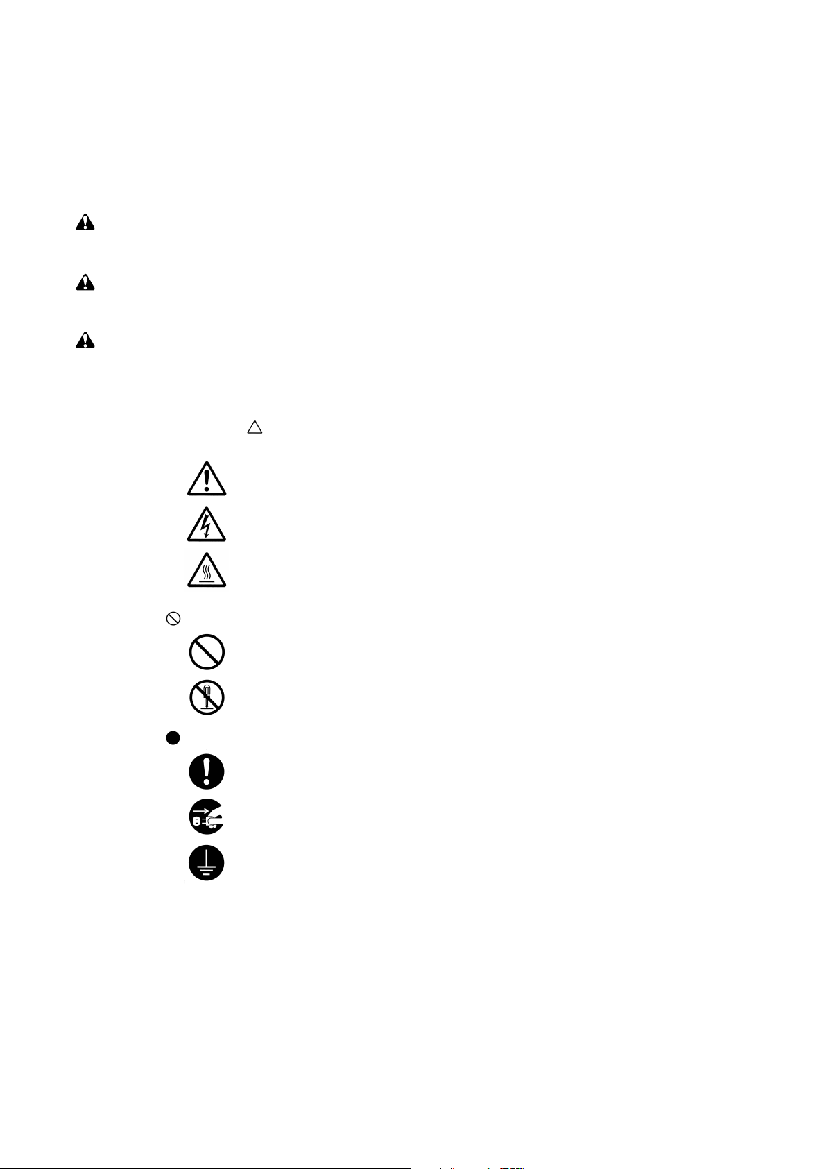
The triangle ( ) symbol indicates a warning including danger and caution. The specific point
of attention is shown inside the symbol.
General warning.
Warning of risk of electric shock.
Warning of high temperature.
indicates a prohibited action. The specific prohibition is shown inside the symbol.
General prohibited action.
Disassembly prohibited.
indicates that action is required. The specific action required is shown inside the symbol.
General action required.
Remove the power plug from the wall outlet.
Always ground the copier.
1. Installation Precautions
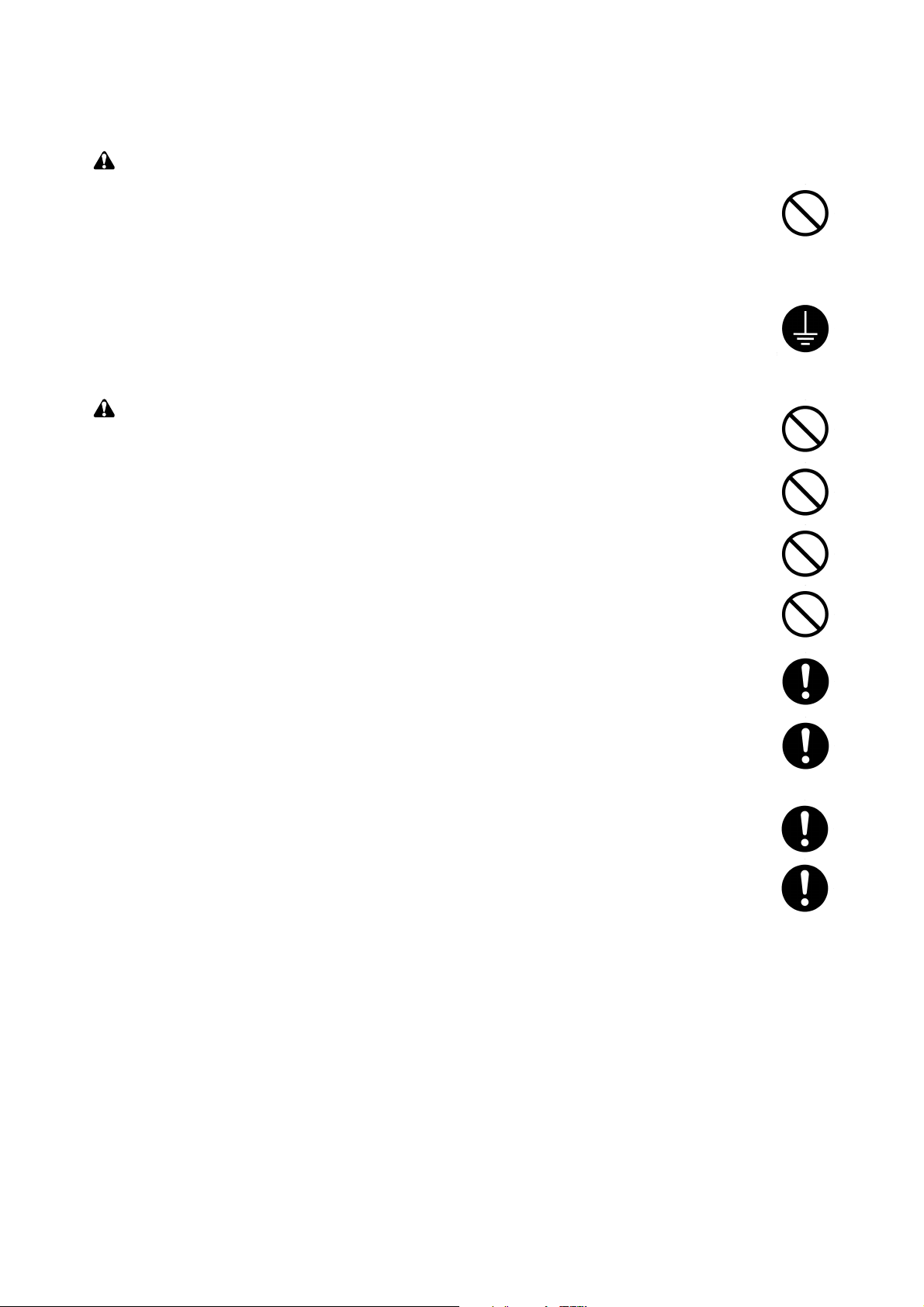
WARNING
• Do not use a power supply with a voltage other than that specified. Avoid multiple connections to
one outlet: they may cause fire or electric shock. When using an extension cable, always check
that it is adequate for the rated current. ............................................................................................
• Connect the ground wire to a suitable grounding point. Not grounding the copier may cause fire or
electric shock. Connecting the earth wire to an object not approved for the purpose may cause
explosion or electric shock. Never connect the ground cable to any of the following: gas pipes,
lightning rods, ground cables for telephone lines and water pipes or faucets not approved by the
proper authorities. .............................................................................................................................
CAUTION:
• Do not place the copier on an infirm or angled surface: the copier may tip over, causing injury. .....
• Do not install the copier in a humid or dusty place. This may cause fire or electric shock. ..............
• Do not install the copier near a radiator, heater, other heat source or near flammable material.
This may cause fire. ..........................................................................................................................
• Allow sufficient space around the copier to allow the ventilation grills to keep the machine as cool
as possible. Insufficient ventilation may cause heat buildup and poor copying performance. ..........
• Always handle the machine by the correct locations when moving it. ..............................................
• Always use anti-toppling and locking devices on copiers so equipped. Failure to do this may
cause the copier to move unexpectedly or topple, leading to injury..................................................
• Avoid inhaling toner or developer excessively. Protect the eyes. If toner or developer is
accidentally ingested, drink a lot of water to dilute it in the stomach and obtain medical attention
immediately. If it gets into the eyes, rinse immediately with copious amounts of water and obtain
medical attention. ..............................................................................................................................
• Advice customers that they must always follow the safety warnings and precautions in the copier’s
instruction handbook. ........................................................................................................................
2. Precautions for Maintenance
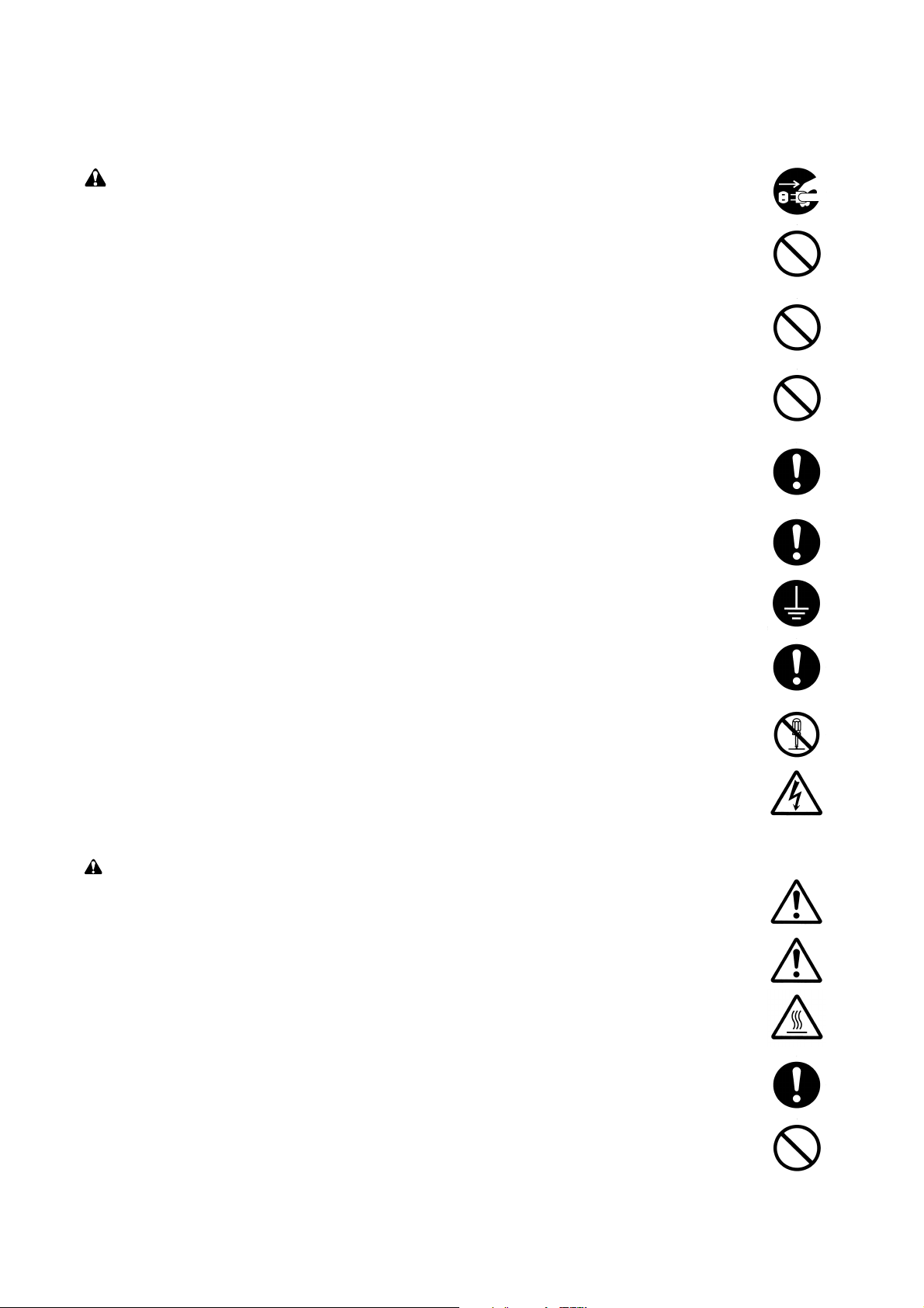
WARNING
• Always remove the power plug from the wall outlet before starting machine disassembly...............
• Always follow the procedures for maintenance described in the service manual and other related
brochures. .........................................................................................................................................
• Under no circumstances attempt to bypass or disable safety features including safety
mechanisms and protective circuits. .................................................................................................
• Always use parts having the correct specifications...........................................................................
• Always use the thermostat or thermal fuse specified in the service manual or other related
brochure when replacing them. Using a piece of wire, for example, could lead to fire or other
serious accident. ...............................................................................................................................
• When the service manual or other serious brochure specifies a distance or gap for installation of a
part, always use the correct scale and measure carefully. ...............................................................
• Always check that the copier is correctly connected to an outlet with a ground connection.............
• Check that the power cable covering is free of damage. Check that the power plug is dust-free. If
it is dirty, clean it to remove the risk of fire or electric shock. ............................................................
• Never attempt to disassemble the optical unit in machines using lasers. Leaking laser light may
damage eyesight. ..............................................................................................................................
• Handle the charger sections with care. They are charged to high potentials and may cause
electric shock if handled improperly. .................................................................................................
CAUTION
• Wear safe clothing. If wearing loose clothing or accessories such as ties, make sure they are
safely secured so they will not be caught in rotating sections...........................................................
• Use utmost caution when working on a powered machine. Keep away from chains and belts........
• Handle the fixing section with care to avoid burns as it can be extremely hot..................................
• Check that the fixing unit thermistor, heat and press rollers are clean. Dirt on them can cause
abnormally high temperatures...........................................................................................................
• Do not remove the ozone filter, if any, from the copier except for routine replacement....................

• Do not pull on the AC power cord or connector wires on high-voltage components when removing
them; always hold the plug itself. ......................................................................................................
• Do not route the power cable where it may be stood on or trapped. If necessary, protect it with a
cable cover or other appropriate item. ..............................................................................................
• Treat the ends of the wire carefully when installing a new charger wire to avoid electric leaks........
• Remove toner completely from electronic components. ...................................................................
• Run wire harnesses carefully so that wires will not be trapped or damaged. ...................................
• After maintenance, always check that all the parts, screws, connectors and wires that were
removed, have been refitted correctly. Special attention should be paid to any forgotten
connector, trapped wire and missing screws. ..................................................................................
• Check that all the caution labels that should be present on the machine according to the
instruction handbook are clean and not peeling. Replace with new ones if necessary. ...................
• Handle greases and solvents with care by following the instructions below: ....................................
· Use only a small amount of solvent at a time, being careful not to spill. Wipe spills off completely.
· Ventilate the room well while using grease or solvents.
· Allow applied solvents to evaporate completely before refitting the covers or turning the main
switch on.
· Always wash hands afterwards.
• Never dispose of toner or toner bottles in fire. Toner may cause sparks when exposed directly to
fire in a furnace, etc...........................................................................................................................
• Should smoke be seen coming from the copier, remove the power plug from the wall outlet
immediately. ......................................................................................................................................
3. Miscellaneous
WARNING
• Never attempt to heat the drum or expose it to any organic solvents such as alcohol, other than
the specified refiner; it may generate toxic gas. ................................................................................

2FD/2FF/2FG-3.0
CONTENTS
1-1 Specifications
1-1-1 Specifications ....................................................................................................................................... 1-1-1
1-1-2 Parts names and their functions........................................................................................................... 1-1-3
(1) Copier ............................................................................................................................................. 1-1-3
(2) Operation panel .............................................................................................................................. 1-1-4
1-1-3 Machine cross section.......................................................................................................................... 1-1-5
1-1-4 Drive system ........................................................................................................................................ 1-1-6
(1) Drive system 1 (drive motor and eject motor drive trains).............................................................. 1-1-6
(2) Drive system 2 (paper feed motor drive train)................................................................................ 1-1-7
(3) Drive system 3 (duplex section) ..................................................................................................... 1-1-8
1-2 Handling Precautions
1-2-1 Drum .................................................................................................................................................... 1-2-1
1-2-2 Toner .................................................................................................................................................... 1-2-1
1-2-3 Installation environment ....................................................................................................................... 1-2-1
1-3 Installation
1-3-1 Unpacking and installation ................................................................................................................... 1-3-1
(1) Installation procedure ..................................................................................................................... 1-3-1
1-3-2 Setting initial copy modes..................................................................................................................... 1-3-8
1-3-3 Installing the key counter (option)........................................................................................................ 1-3-9
1-3-4 Installing the drawer heater (option)................................................................................................... 1-3-11
1-3-5 Installing the paper feeder (option) .................................................................................................... 1-3-13
1-3-6 Installing the large paper deck (option).............................................................................................. 1-3-17
1-3-7 Installing the booklet stitcher/switchback unit (option)....................................................................... 1-3-22
1-3-8 Installing the sheet-through document processor (option)................................................................. 1-3-33
1-3-9 Installing the Printing System (option)................................................................................................ 1-3-34
1-3-10 Installing the Scanning System (option)............................................................................................. 1-3-36
1-3-11 Installing the built-in finisher (option).................................................................................................. 1-3-39
1-3-12 Installing the job separator (option).................................................................................................... 1-3-45
1-3-13 Installing the Facsimile System (option)............................................................................................. 1-3-48
1-3-14 Installing the hard disk (option) .......................................................................................................... 1-3-56
1-3-15 Installing the 1000-sheet finisher (option).......................................................................................... 1-3-58
1-3-16 Installing the 3000-sheet finisher (option).......................................................................................... 1-3-63
1-4 Maintenance Mode
1-4-1 Copier management............................................................................................................................. 1-4-1
(1) Using the copier management mode.............................................................................................. 1-4-1
(2) Setting department management items.......................................................................................... 1-4-2
(3) Copy default ................................................................................................................................... 1-4-3
(4) Machine default .............................................................................................................................. 1-4-6
(5) Bypass setting ................................................................................................................................ 1-4-7
(6) Original size registration................................................................................................................. 1-4-7
(7) User adjustment ............................................................................................................................. 1-4-8
(8) Checking the total counter and printing out the counter report....................................................... 1-4-8
(9) Doucment management default setting.......................................................................................... 1-4-8
(10) Hard disk management .................................................................................................................. 1-4-8
(11) Status report print out..................................................................................................................... 1-4-8
(12) Language selection function........................................................................................................... 1-4-8
1-4-2 Maintenance mode............................................................................................................................... 1-4-9
(1) Executing a maintenance item ....................................................................................................... 1-4-9
(2) Maintenance mode item list.......................................................................................................... 1-4-10
(3) Contents of maintenance mode items.......................................................................................... 1-4-14
1-1-1

2FD/2FF/2FG
1-5 Troubleshooting
1-5-1 Paper misfeed detection ...................................................................................................................... 1-5-1
(1) Paper misfeed indication ................................................................................................................ 1-5-1
(2) Paper misfeed detection conditions ................................................................................................ 1-5-2
(3) Paper misfeeds ............................................................................................................................... 1-5-9
1-5-2 Self-diagnosis ..................................................................................................................................... 1-5-20
(1) Self-diagnostic function ................................................................................................................ 1-5-20
(2) Self-diagnostic codes ................................................................................................................... 1-5-21
1-5-3 Image formation problems ................................................................................................................. 1-5-37
(1) No image appears (entirely white). ............................................................................................... 1-5-38
(2) No image appears (entirely black). ............................................................................................... 1-5-39
(3) Image is too light. ......................................................................................................................... 1-5-40
(4) Background is visible. ................................................................................................................... 1-5-40
(5) A white line appears longitudinally. .............................................................................................. 1-5-40
(6) A black line appears longitudinally. .............................................................................................. 1-5-41
(7) A black line appears laterally. ....................................................................................................... 1-5-41
(8) One side of the copy image is darker than the other. ................................................................... 1-5-41
(9) Black dots appear on the image. .................................................................................................. 1-5-42
(10) Image is blurred. ........................................................................................................................... 1-5-42
(11) The leading edge of the image is consistently misaligned with the original. ................................ 1-5-42
(12) The leading edge of the image is sporadically misaligned with the original. ................................ 1-5-43
(13) Paper creases. ............................................................................................................................. 1-5-43
(14) Offset occurs. ............................................................................................................................... 1-5-43
(15) Image is partly missing. ................................................................................................................ 1-5-44
(16) Fixing is poor. ............................................................................................................................... 1-5-44
(17) Image is out of focus. ................................................................................................................... 1-5-44
(18) Image center does not align with the original center. ................................................................... 1-5-45
(19) Image is not square. ..................................................................................................................... 1-5-45
1-5-4 Electrical problems ............................................................................................................................. 1-5-46
(1) The machine does not operate when the power switch is turned on. ........................................... 1-5-46
(2) The drive motor does not operate (C2000). ................................................................................. 1-5-46
(3) The paper feed motor does not operate (C2500). ........................................................................ 1-5-46
(4) The eject motor does not operate. ................................................................................................ 1-5-46
(5) The upper lift motor does not operate (C1010). ........................................................................... 1-5-47
(6) The lower lift motor does not operate (C1020). ............................................................................ 1-5-47
(7) The scanner motor does not operate. .......................................................................................... 1-5-47
(8) Cooling fan motor 1 does not operate. ......................................................................................... 1-5-47
(9) Cooling fan motor 2 does not operate. ......................................................................................... 1-5-47
(10) Cooling fan motor 3 does not operate. ......................................................................................... 1-5-47
(11) Cooling fan motor 4 does not operate. ......................................................................................... 1-5-47
(12) Cooling fan motor 5 does not operate. ......................................................................................... 1-5-48
(13) Cooling fan motor 6 does not operate. ......................................................................................... 1-5-48
(14) Cooling fan motor 7 does not operate. ......................................................................................... 1-5-48
(15) The upper paper feed clutch does not operate. ............................................................................ 1-5-48
(16) The lower paper feed clutch does not operate. ............................................................................ 1-5-48
(17) Feed clutch 1 does not operate. ................................................................................................... 1-5-48
(18) Feed clutch 2 does not operate. ................................................................................................... 1-5-48
(19) Feed clutch 3 does not operate. ................................................................................................... 1-5-49
(20) The bypass paper feed clutch does not operate. ......................................................................... 1-5-49
(21) The bypass feed clutch does not operate. .................................................................................... 1-5-49
(22) The registration clutch does not operate. ..................................................................................... 1-5-49
(23) The duplex feed clutch does not operate. .................................................................................... 1-5-49
(24) The feedshift solenoid does not operate. ..................................................................................... 1-5-49
(25) The toner feed solenoid does not operate. ................................................................................... 1-5-50
(26) The cleaning lamp does not turn on. ............................................................................................ 1-5-50
(27) The exposure lamp does not turn on. ........................................................................................... 1-5-50
(28) The exposure lamp does not turn off. ........................................................................................... 1-5-50
(29) The fixing heater does not turn on (C6000). ................................................................................. 1-5-50
1-1-2

2FD/2FF/2FG
(30) The fixing heater does not turn off. ............................................................................................... 1-5-50
(31) Main charging is not performed. ................................................................................................... 1-5-50
(32) Transfer charging is not performed. ............................................................................................. 1-5-51
(33) No developing bias is output. ....................................................................................................... 1-5-51
(34) The original size is not detected. .................................................................................................. 1-5-51
(35) The original size is not detected correctly. ................................................................................... 1-5-51
(36) The touch panel keys do not work. ............................................................................................... 1-5-51
(37) The message requesting paper to be loaded is shown
when paper is present in the upper drawer. ................................................................................. 1-5-51
(38) The message requesting paper to be loaded is shown
when paper is present in the lower drawer. .................................................................................. 1-5-51
(39) The message requesting paper to be loaded is shown
when paper is present on the bypass tray. ................................................................................... 1-5-51
(40) The size of paper in the upper drawer is not displayed correctly. ................................................ 1-5-52
(41) The size of paper in the lower drawer is not displayed correctly. ................................................. 1-5-52
(42) The printing width of the paper on the bypass tray is not detected correctly. ............................... 1-5-52
(43) A paper jam in the paper feed, paper conveying or fixing section is indicated
when the power switch is turned on. ............................................................................................ 1-5-53
(44) The message requesting covers to be closed is displayed
when the front cover and conveying cover are closed. ................................................................ 1-5-53
(45) Others. .......................................................................................................................................... 1-5-53
1-5-5 Mechanical problems ......................................................................................................................... 1-5-54
(1) No primary paper feed. ................................................................................................................. 1-5-54
(2) No secondary paper feed. ............................................................................................................ 1-5-54
(3) Skewed paper feed. ...................................................................................................................... 1-5-54
(4) The scanner does not travel. ........................................................................................................ 1-5-54
(5) Multiple sheets of paper are fed at one time.................................................................................. 1-5-54
(6) Paper jams. .................................................................................................................................. 1-5-54
(7) Toner drops on the paper conveying path. ................................................................................... 1-5-55
(8) Abnormal noise is heard. .............................................................................................................. 1-5-55
1-6 Assembly and Disassembly
1-6-1 Precautions for assembly and disassembly ......................................................................................... 1-6-1
(1) Precautions ..................................................................................................................................... 1-6-1
(2) Running a maintenance item .......................................................................................................... 1-6-2
1-6-2 Paper feed section ............................................................................................................................... 1-6-3
(1) Detaching and refitting the forwarding, paper feed and separation pulleys .................................... 1-6-3
(2) Detaching and refitting the bypass separation, bypass papaer feed and
bypass forwarding pulleys .............................................................................................................. 1-6-5
(3) Adjustment after roller and clutch replacement ............................................................................ 1-6-10
(3-1) Adjusting the leading edge registration of image printing .................................................... 1-6-10
(3-2) Adjusting the leading edge registration for memory image printing ..................................... 1-6-11
(3-3) Adjusting the center line of image printing ........................................................................... 1-6-12
(3-4) Adjusting the margins for printing ........................................................................................ 1-6-13
(3-5) Adjusting the amount of slack in the paper .......................................................................... 1-6-14
1-6-3 Optical section .................................................................................................................................... 1-6-15
(1) Detaching and refitting the exposure lamp ................................................................................... 1-6-15
(2) Detaching and refitting the scanner wires .................................................................................... 1-6-16
(2-1) Detaching the scanner wires ............................................................................................... 1-6-16
(2-2) Refitting the scanner wires .................................................................................................. 1-6-17
(3) Detaching and refitting the laser scanner unit .............................................................................. 1-6-20
(4) Adjusting the skew of the laser scanner unit (reference) .............................................................. 1-6-22
(5) Detaching and refitting the ISU (reference) .................................................................................. 1-6-23
(6) Adjusting the position of the ISU (reference) ................................................................................ 1-6-25
(7) Adjusting the longitudinal squareness (reference) ....................................................................... 1-6-26
(8) Adjusting magnification of the scanner in the main scanning direction ........................................ 1-6-27
(9) Adjusting magnification of the scanner in the auxiliary scanning direction ................................... 1-6-28
(10) Adjusting the scanner leading edge registration ........................................................................... 1-6-29
(11) Adjusting the scanner center line ................................................................................................. 1-6-30
(12) Adjusting the margins for scanning an original on the contact glass ............................................ 1-6-31
1-1-3

2FD/2FF/2FG-3.0
1-6-4 Drum section ...................................................................................................................................... 1-6-32
(1) Detaching and refitting the drum unit............................................................................................ 1-6-32
(2) Detaching and refitting the main charger unit............................................................................... 1-6-32
(3) Detaching and refitting the drum separation claw assemblies..................................................... 1-6-33
1-6-5 Developing section............................................................................................................................. 1-6-34
(1) Detaching and refitting the developing unit.................................................................................. 1-6-34
1-6-6 Transfer section ................................................................................................................................. 1-6-35
(1) Detaching and refitting the transfer roller assembly..................................................................... 1-6-35
1-6-7 Fixing section ..................................................................................................................................... 1-6-36
(1) Detaching and refitting the fixing unit ........................................................................................... 1-6-36
(2) Detaching and refitting the heat roller separation claws............................................................... 1-6-36
(3) Detaching and refitting the press roller......................................................................................... 1-6-37
(4) Detaching and refitting the fixing heater M and S......................................................................... 1-6-38
(5) Detaching and refitting the heat roller........................................................................................... 1-6-39
(6) Detaching and refitting the fixing unit thermistor 1 and 2............................................................. 1-6-40
(7) Adjusting front position of the fixing unit (adjusting lateral squareness)....................................... 1-6-41
1-6-8 Others ................................................................................................................................................ 1-6-42
(1) Detaching and refitting the ozone filters (only for 230 V specifications)....................................... 1-6-42
1-7 Requirements on PCB Replacement
1-7-1 Upgrading the firmware on the main PCB............................................................................................ 1-7-1
1-7-2 Adjustment-free variable resisters (VR)............................................................................................... 1-7-2
1-7-3 Remarks on main PCB replacement.................................................................................................... 1-7-2
1-7-4 Upgrading the the printer board firmware ............................................................................................ 1-7-3
2-1 Mechanical construction
2-1-1 Paper feed section ............................................................................................................................... 2-1-1
2-1-2 Main charging section .......................................................................................................................... 2-1-5
2-1-3 Optical section...................................................................................................................................... 2-1-7
(1) Original scanning............................................................................................................................ 2-1-8
(2) Image printing................................................................................................................................. 2-1-9
2-1-4 Developing section............................................................................................................................. 2-1-12
(1) Formation of magnetic brush........................................................................................................ 2-1-13
(2) Computing the absolute humidity................................................................................................. 2-1-14
(3) Single component developing system.......................................................................................... 2-1-15
2-1-5 Transfer and separation sections....................................................................................................... 2-1-17
2-1-6 Cleaning and charge erasing sections............................................................................................... 2-1-19
2-1-7 Fixing section ..................................................................................................................................... 2-1-20
2-1-8 Eject and switchback sections............................................................................................................ 2-1-22
2-1-9 Duplex section.................................................................................................................................... 2-1-24
(1) Paper conveying operation in duplex copying.............................................................................. 2-1-25
2-2 Electrical Parts Layout
2-2-1 Electrical parts layout ........................................................................................................................... 2-2-1
(1) PCBs .............................................................................................................................................. 2-2-1
(2) Switches and sensors..................................................................................................................... 2-2-2
(3) Motors............................................................................................................................................. 2-2-4
(4) Other electrical components........................................................................................................... 2-2-5
2-3 Operation of the PCBs
2-3-1 Power source PCB............................................................................................................................... 2-3-1
2-3-2 Main PCB ............................................................................................................................................. 2-3-5
2-3-3 Operation unit PCB ............................................................................................................................ 2-3-17
2-3-4 Scanner drive PCB............................................................................................................................. 2-3-22
2-3-5 CCD PCB ........................................................................................................................................... 2-3-25
1-1-4

2FD/2FF/2FG-3.0
2-4 Appendixes
Timing chart No. 1 .......................................................................................................................................... 2-4-1
Timing chart No. 2 .......................................................................................................................................... 2-4-2
Timing chart No. 3 .......................................................................................................................................... 2-4-3
Timing chart No. 4 .......................................................................................................................................... 2-4-4
Timing chart No. 5 .......................................................................................................................................... 2-4-5
Timing chart No. 6 .......................................................................................................................................... 2-4-6
Timing chart No. 7 .......................................................................................................................................... 2-4-7
Timing chart No. 8 .......................................................................................................................................... 2-4-8
Timing chart No. 9 .......................................................................................................................................... 2-4-9
Timing chart No. 10 ...................................................................................................................................... 2-4-10
Timing chart No. 11 ...................................................................................................................................... 2-4-11
Chart of image adjustment procedures........................................................................................................ 2-4-12
Maintenance parts list................................................................................................................................... 2-4-15
Periodic maintenance procedures................................................................................................................ 2-4-16
Optional devices supplied parts list.............................................................................................................. 2-4-18
General wiring diagram ................................................................................................................................ 2-4-20
1-1-5

1-1-1 Specifications
Type ...............................................Desktop
Copying system .............................Indirect electrostatic system
Originals .........................................Sheets and books
Maximum size: A3/11" × 17"
Original feed system ......................Fixed
Copy paper ....................................Drawer: Plain paper (64 – 105 g/m
Bypass table: Plain paper (45 – 200 g/m
Special paper: Transparencies, tracing paper, colored paper, letterhead and
envelopes (when using the printer function only)
Note: Use the bypass table for special paper.
Copying sizes.................................Maximum: A3/11" × 17"
Minimum: A6R/5
1
/2" × 81/2" (When the bypass table is used)
Magnification ratios ........................Manual mode: 25 – 400%, 1% increments
Auto copy mode: fixed ratios
Metric
1:1 ± 1.0%, 1:4.00/1:2.00/1:1.41/1:1.22/1:1.15/1:0.86/1:0.81/1:0.70/1:0.50/1:0.25
Inch
1:1 ± 1.0%, 1:4.00/1:2.00/1:1.29/1:1.21/1:0.78/1:0.64/1:0.50/1:0.25
Copy speed....................................At 100% magnification in copy mode:
30 cpm copier
A3/11" × 17": 20 copies/min.
1
B4/8
/2" × 14": 20 copies/min.
A4/11" × 8
A4R/8
1
/2": 30 copies/min.
1
/2" × 11": 22 copies/min.
B5: 30 copies/min.
B5R: 18 copies/min.
40 cpm copier
A3/11" × 17": 23 copies/min.
1
B4/8
/2" × 14": 23 copies/min.
A4/11" × 8
A4R/8
1
/2": 40 copies/min.
1
/2" × 11": 27 copies/min.
B5: 40 copies/min.
B5R: 22 copies/min.
50 cpm copier
A3/11" × 17": 26 copies/min.
1
B4/8
" × 14": 26 copies/min.
/
2
A4/11" × 8
A4R/8
1
/2": 50 copies/min.
1
/2" × 11": 31 copies/min.
B5: 50 copies/min.
B5R: 24 copies/min.
First copy time................................From 3.9 s (A4/11" × 8
From 3.5 s (A4/11" × 8
1
/2") <30 cpm copier>
1
/2") <40 cpm copier/50 cpm copier>
Warm-up time.................................25 s or less (room temperature 23°C/73.4°F, 50% RH)
In preheat/energy saver mode: 12 s or less (room temperature 23°C/73.4°F, 50%
RH) [priorty to power save]
Paper feed system .........................Automatic feed
Capacity:
Drawers: 500 sheets
Manual feed
Capacity:
Bypass: 200 sheets
Continuous copying .......................1 - 999 sheets
Photoconductor..............................a-Si (drum diameter 40 mm)
Charging system ............................Single positive corona charging (500 µA)
Exposure light source ....................Semiconductor laser
Exposure scanning system............Polygon mirror
Developing system.........................Dry, reverse developing (single component system)
Developer: 1-component, magnetism toner
Developing bias: +1.72 kV AC
Developing shift bias: 160 V
Toner replenishing: automatic from a toner container
2
)
2
)
2FD/2FF/2FG-3.0
1-1-1

2FD/2FF/2FG-3.0
Tr ansfer system .............................Transfer roller (100 µA)
Separation system .........................Separation electrode (60 or 10 µA depending on the paper)
Fixing system .................................Heat roller
Heat source: halogen heaters (120 V specifications:main 600 W, sub 500 W/220-240
V specifications:main 640 W, sub 534 W)
Control temperature: 175°C/347°F (at normal ambient temperature, 50 cpm copier)
170°C/338°F (at normal ambient temperature, 40 cpm copier)
165°C/329°F (at normal ambient temperature, 30 cpm copier)
Abnormally high temperature protection device: 170°C/338°F thermostat
Fixing pressure: 107.8 N
Charge erasing system..................Exposure by cleaning lamp
Cleaning system.............................Cleaning blade and roller
Scanning system............................Flat bed scanning by CCD image sensor
Bit map memory.............................27 MB (standard)
Image storage memory..................37 MB (standard)
Resolution ......................................600 × 600 dpi
Light source....................................Inert gas lamp
Dimensions ....................................585 (W) × 646 (D) × 745 (H) mm
23" (W) × 25
2
/5" (D) × 291/3" (H)
Weight ............................................Approx. 82 kg/165 lbs
Floor requirements.........................1512 (W) × 646 (D) mm
1
59
/2" (W) × 252/5" (D)
Functions........................................Auto paper selection mode, Image quality selection, Auto magnification selection
mode, Zoom mode, Preset zoom mode, XY zoom mode, 2-sided copy modes, Page
separation/Split copy modes, Margin mode, Centering/Image shift mode, Memo
mode, Border erase modes, Combine/Merge Copy modes, Print page numbers
mode, Form overlay mode, Booklet/Stitching mode, Book to Booklet mode, Sort/
Finished mode, Auto rotation function, Cover mode, Transparency + backing sheet
mode, Invert mode, Mirror image mode, Proof mode, Repeat copy mode*, Batch
scanning mode, Eco print mode, Program function, Job build mode, Form
registration*, Shared data box*, Synergy print boxes*, Copy management mode,
Language selection function
*Requires the optional hard disk
Power source .................................120 V AC, 60 Hz, 12 A Max.
220 – 240 V AC, 50/60 Hz, 6.5 A Max.
Power consumption........................Max. 1450 W
Options...........................................DP, paper feeder, large paper deck, job separator, 3000-sheet finisher, 1000-sheet
finisher, booklet stitcher, built-in finisher, key counter, fax board, printer board,
network printer board, network scanner board, hard disk
1-1-2
1-1-2 Parts names and their functions
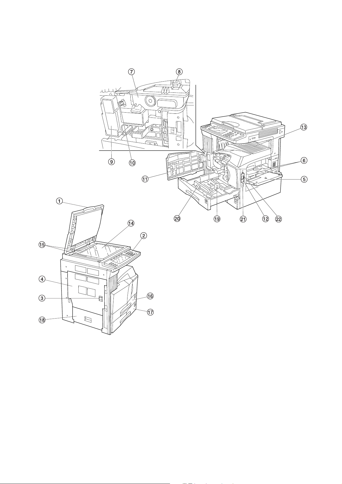
(1) Copier
2FD/2FF/2FG-3.0
1 Original cover
2 Operation panel
3 Conveying cover handle
4 Conveying cover
5 Bypass tray
6 Insert guides
7 Toner container
8 Toner container release lever
9 Toner disposal tank
0 Cleaning shaft
! Front cover
@ Main power switch
Figure 1-1-1
# Copy store section
$ Platen
% Original size scales
^ Upper drawer
& Lower drawer
* Side cover
( Length adjustment plate
) Width adjustment lever
⁄ Handles for transport
¤ Main power switch cover*
*: Only for metric specifications.
1-1-3
2FD/2FF/2FG-3.0
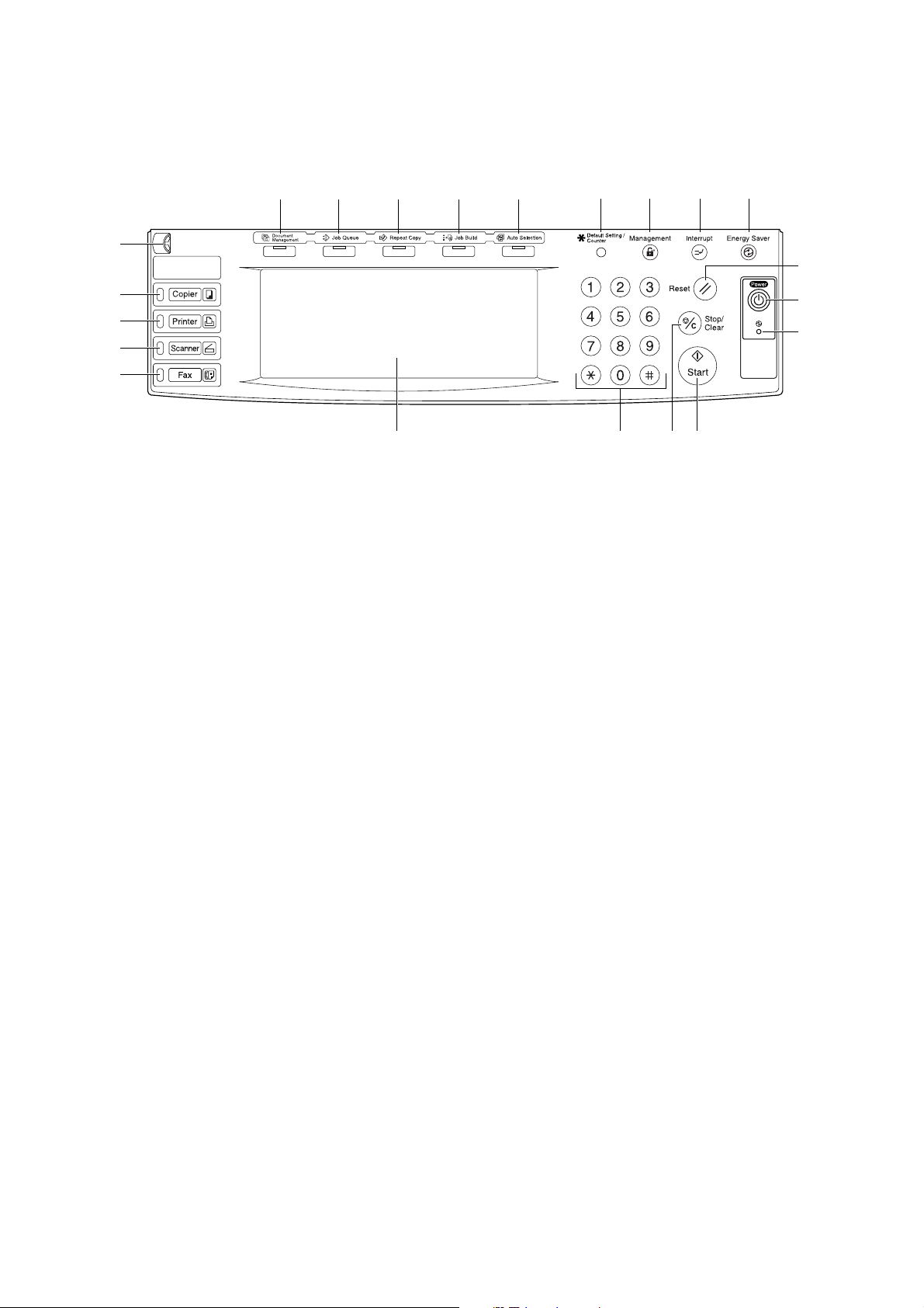
(2) Operation panel
0
(* &^ % 7654
3
!
@
#
$
1 Start key (Indicator lamp)
2 Stop/clear key
3 Reset key
4 Energy Saver (preheat) key
5 Interrupt key (Indicator lamp)
6 Management key
7 Default Setting/Counter key
8 Numeric key
9 Touch panel
0 Brightness adjustment control dial
! Copier key (Indicator lamp)
)
⁄
1289
Figure 1-1-2
@ Printer key (Indicator lamp)
# Scanner key (Indicator lamp)
$ Fax key (Indicator lamp)
% Auto Selection key (Indicator lamp)
^ Job Build key (Indicator lamp)
& Repeat Copy key (Indicator lamp)
* Job Queue key (Indicator lamp)
( Document Management key (Indicator lamp)
) Power key (Indicator lamp)*
⁄ Main power Indicator lamp*
*: Only for metric specifications.
1-1-4
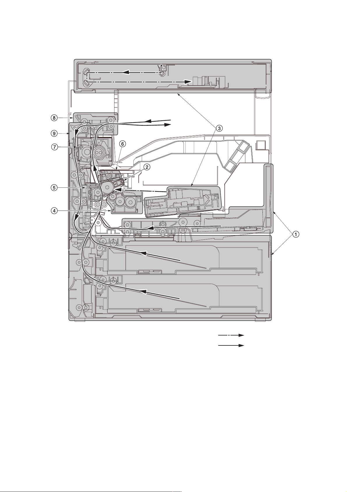
1-1-3 Machine cross section
2FD/2FF/2FG
Figure 1-1-3 Machine cross section
1 Paper feed section
2 Main charging section
3 Optical section
4 Developing section
5 Transfer and separation section
6 Cleaning and charge erasing section section
7 Fixing section
8 Eject and switchback section
9 Duplex section
Light path
Paper path
1-1-5

2FD/2FF/2FG
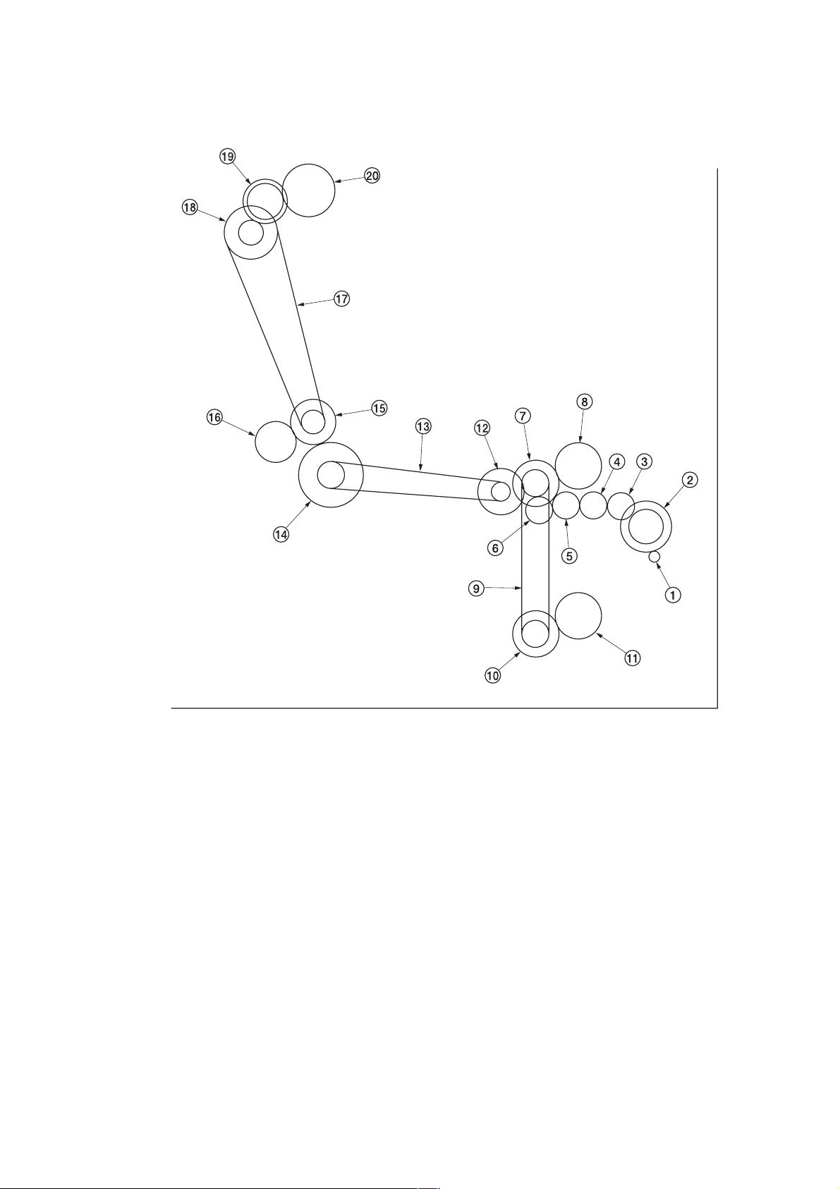
1-1-4 Drive system
(1) Drive system 1 (drive motor and eject motor drive trains)
1-1-6
1 Drive motor gear
2 Drum gear Z76H/Z30H
3 Drum gear Z70H
4 Gear Z76H/Z35H
5 Gear Z50H
6 Gear Z36S/Z31H
7 Gear Z37H/28H
8 Gear Z34H
As viewed from machine rear
Figure 1-1-4
9 Registration clutch gear
0 Gear Z63H/Z45S
! Gear Z37S
@ Gear Z24S
# Joint gear Z32S
$ Eject motor gear
% Gear Z47S/Z28S
^ Eject gear Z30S
(2) Drive system 2 (paper feed motor drive train)
2FD/2FF/2FG
1 Paper feed motor gear
2 Gear Z76H/Z35S
3 Feed gear Z25
4 Feed gear Z25
5 Feed gear Z25
6 Feed gear Z25
7 Gear Z41S/Z24S/P30
8 Upper paper feed clutch gear
9 Paper feed drive belt
0 Gear Z41S/Z24S
As viewed from machine rear
Figure 1-1-5
! Lower paper feed clutch gear
@ Gear Z41S/P15
# Bypass drive belt
$ Gear Z60S/P20
% Gear Z41S/P18
^ Gear Z40S/Z32S
& Container drive belt
* Gear Z24S/P40
( Gear Z40S/Z25S
) Container gear
1-1-7
2FD/2FF/2FG
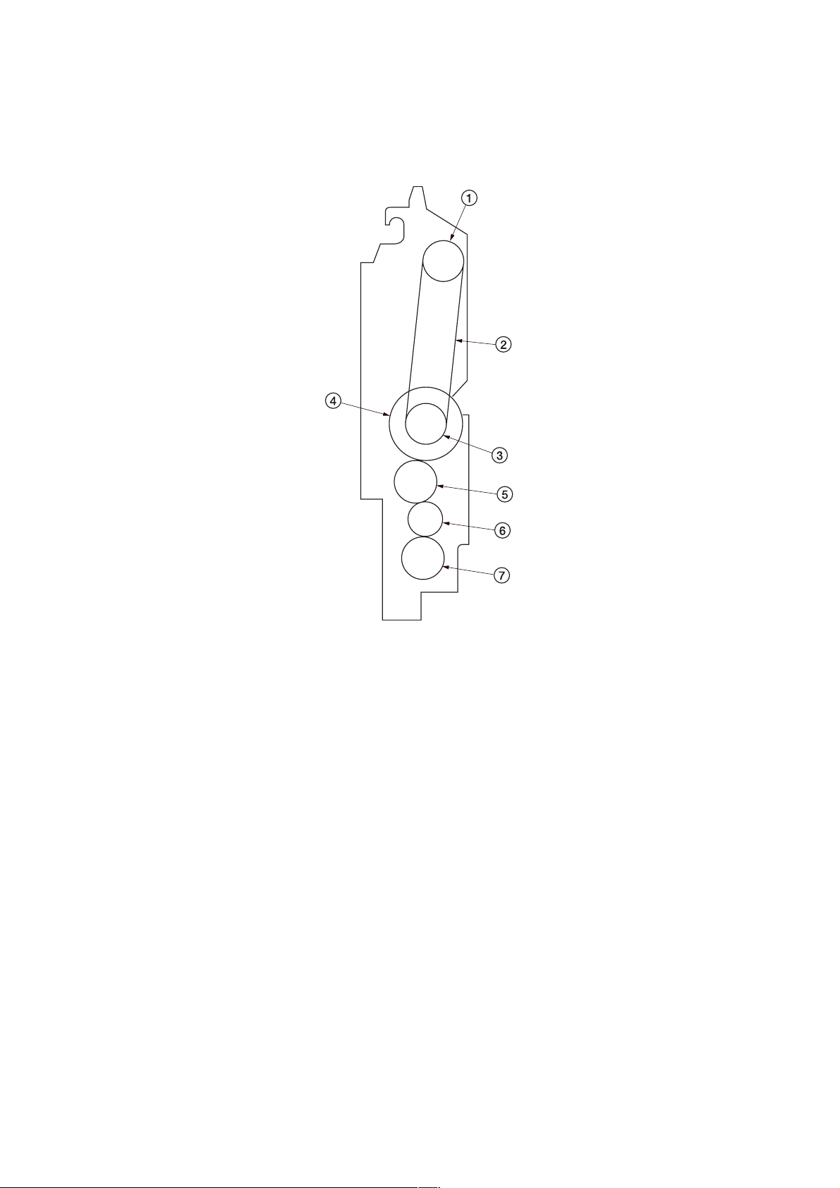
(3) Drive system 3 (duplex section)
Figure 1-1-6
1 Pulley T30
2 Duplex belt
3 Pulley T30
4 Duplex feed clutch gear
5 Gear 25
6 Idle gear 20
7 Gear 25
1-1-8
2FD/2FF/2FG
1-2-1 Drum
Note the following when handling or storing the drum.
• When removing the drum unit, never expose the drum surface to strong direct light.
• Keep the drum at an ambient temperature between 0°C/32°F and 35°C/95°F and at a relative humidity not higher than
85% RH. Avoid abrupt changes in temperature and humidity.
• Avoid exposure to any substance which is harmful to or may affect the quality of the drum.
• Do not touch the drum surface with any object. Should it be touched by hands or stained with oil, clean it.
1-2-2 Toner
Store the toner in a cool, dark place. Avoid direct light and high humidity.
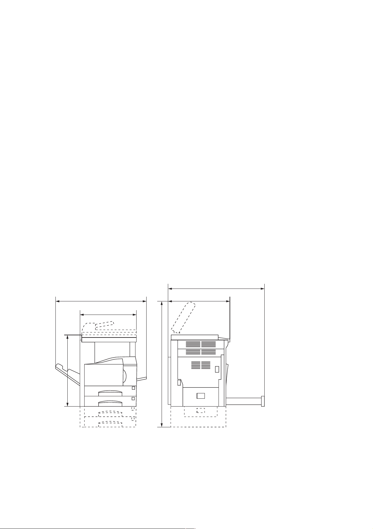
1-2-3 Installation environment
1. Temperature: 10 - 35°C/50 - 95°F
2. Humidity: 15 - 85%RH
3. Power supply: 120 V AC, 12 A
4. Power source frequency: 50 Hz ±0.3%/60 Hz ±0.3%
5. Installation location
• Avoid direct sunlight or bright lighting. Ensure that the photoconductor will not be exposed to direct sunlight or other
strong light when removing paper jams.
• Avoid extremes of temperature and humidity, abrupt ambient temperature changes, and hot or cold air directed onto
the machine.
• Avoid dust and vibration.
• Choose a surface capable of supporting the weight of the machine.
• Place the machine on a level surface (maximum allowance inclination: 1° ).
• Avoid air-borne substances that may adversely affect the machine or degrade the photoconductor, such as
mercury, acidic of alkaline vapors, inorganic gasses, NOx, SOx gases and chlorine-based organic solvents.
• Select a room with good ventilation.
6. Allow sufficient access for proper operation and maintenance of the machine.
Machine front: 1000 mm/39
Machine right: 300 mm/1113/16" Machine left: 300 mm/1113/16"
220 - 240 V AC, 5.7 A (Average)
3
/8" Machine rear: 300 mm/1113/16"
f
ec
b
5
3
13
/16"
/8"
7
/16"
/16"
a: 745 mm/29
b: 585 mm/23"
c: 646 mm/25
d: 1510 mm/59
a
d
e: 1032 mm/405/8"
f: 961 mm/37
Figure 1-2-1 Installation dimensions
1-2-1
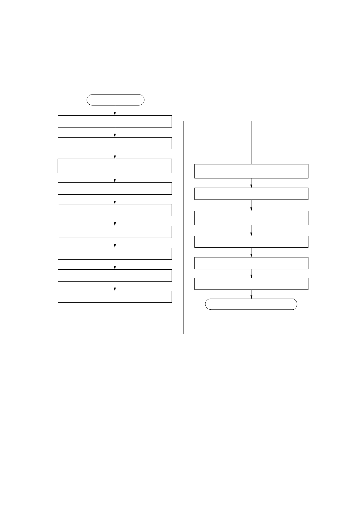
1-3-1 Unpacking and installation
(1) Installation procedure
Start
Unpack.
Remove the tapes and pad.
2FD/2FF/2FG
Install the optional paper feeder or
large paper deck.
Remove the pins holding light source units 1 and 2.
Install the original cover or the DP.
Install other optional devices.
Install the toner container.
Install the toner disposal tank.
Connect the power cord.
Carry out initial developer setting
(maintenance item U130).
Load paper.
Output an own-status report
(maintenance item U000).
Exit maintenance mode.
Print out the user setting list.
Make test copies.
Completion of the machine installation.
1-3-1
2FD/2FF/2FG
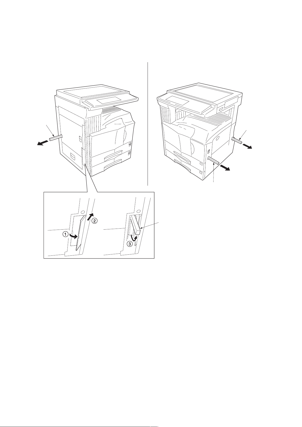
Moving the machine
When moving the machine, pull out the four handles for transport on the right and left sides and hold them.
* For the left front handle for transport, open the door and push it into the machine before pulling out the handle.
Handle for
transport
Handle for
transport
Figure 1-3-1
Handle for
transport
Handle for
transport
1-3-2
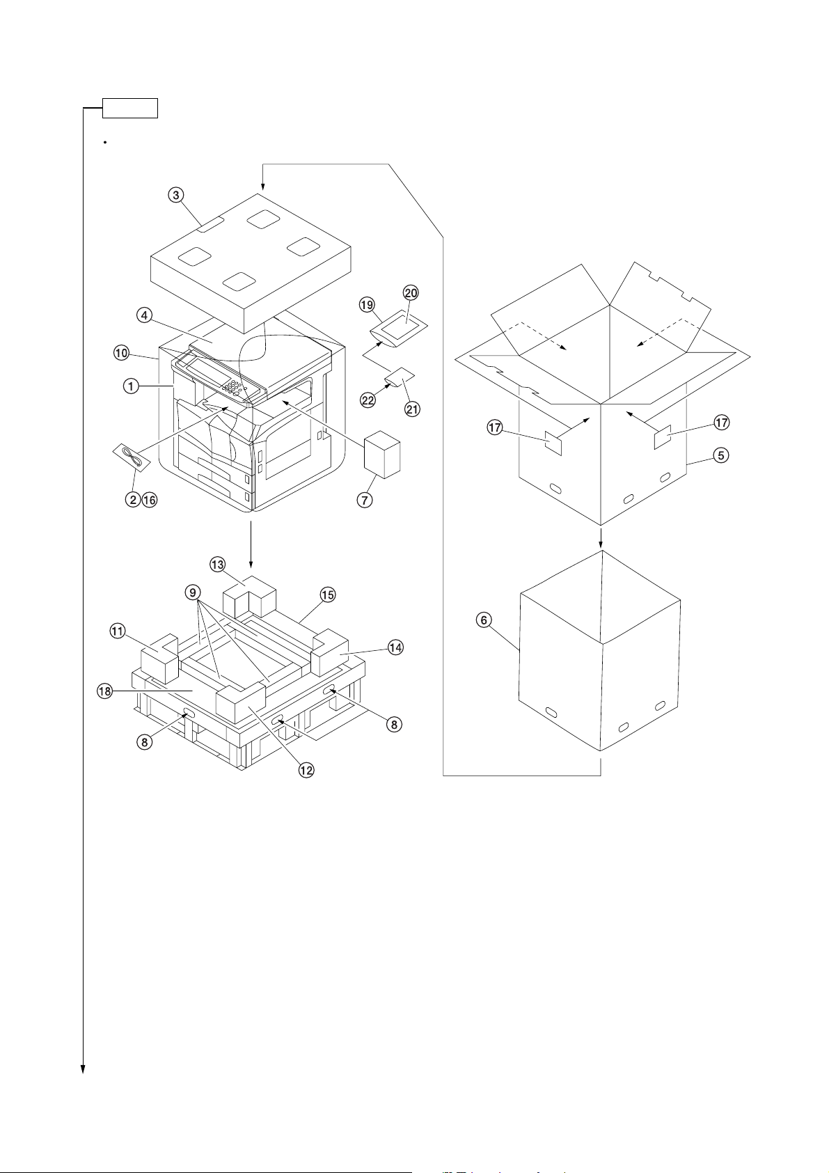
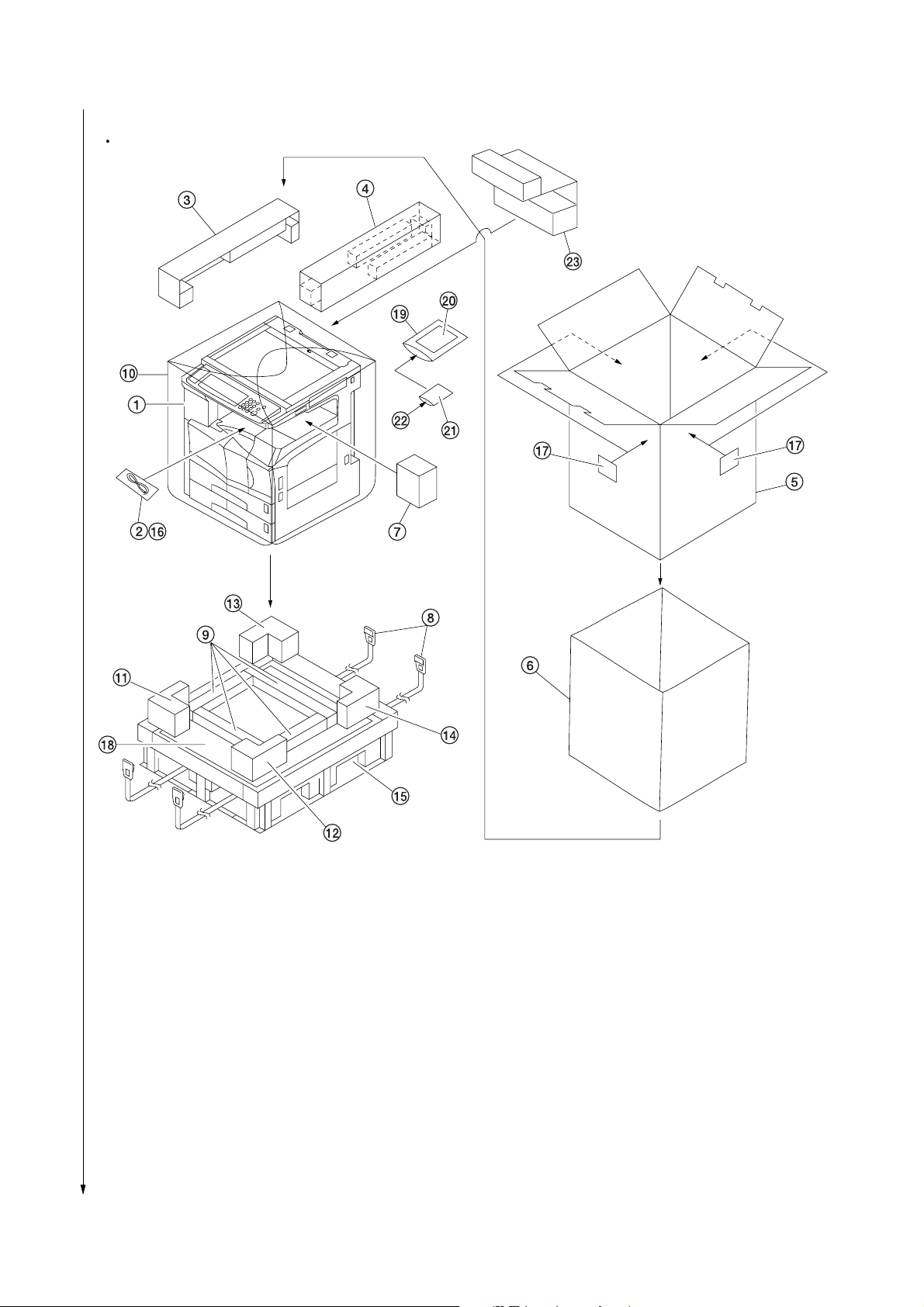
Unpack.
120 V specifications
2FD/2FF/2FG-3.0
Figure 1-3-2a Unpacking
1 Copier
2 Power cord
3 Upper pad
4 Sheet
5 Outer case
6 Inner frame
7 Eject spacer
8 Hinge joints
9 Bottom pad
0 Machine cover
! Front left pad
Caution: Place the machine on a level surface.
@ Front right pad
# Rear left pad
$ Rear right pad
% Skid
^ Plastic bag
& Bar code labels
* Bottom spacer
( Plastic bag
) Operation guide
⁄ Plastic bag
¤ M3 x 8 screws
1-3-3
2FD/2FF/2FG-3.0
230 V specifications
1-3-4
Figure 1-3-2b Unpacking
1 Copier
2 Power cord
3 Upper left pad
4 Upper right pad
5 Outer case
6 Inner frame
7 Eject spacer
8 Belts
9 Bottom pad
0 Machine cover
! Front left pad
@ Front right pad
Caution: Place the machine on a level surface.
# Rear left pad
$ Rear right pad
% Skid
^ Plastic bag
& Bar code labels
* Bottom spacer
( Plastic bag
) Operation guide
⁄ Plastic bag
¤ M3 x 8 screws
‹ Spacer
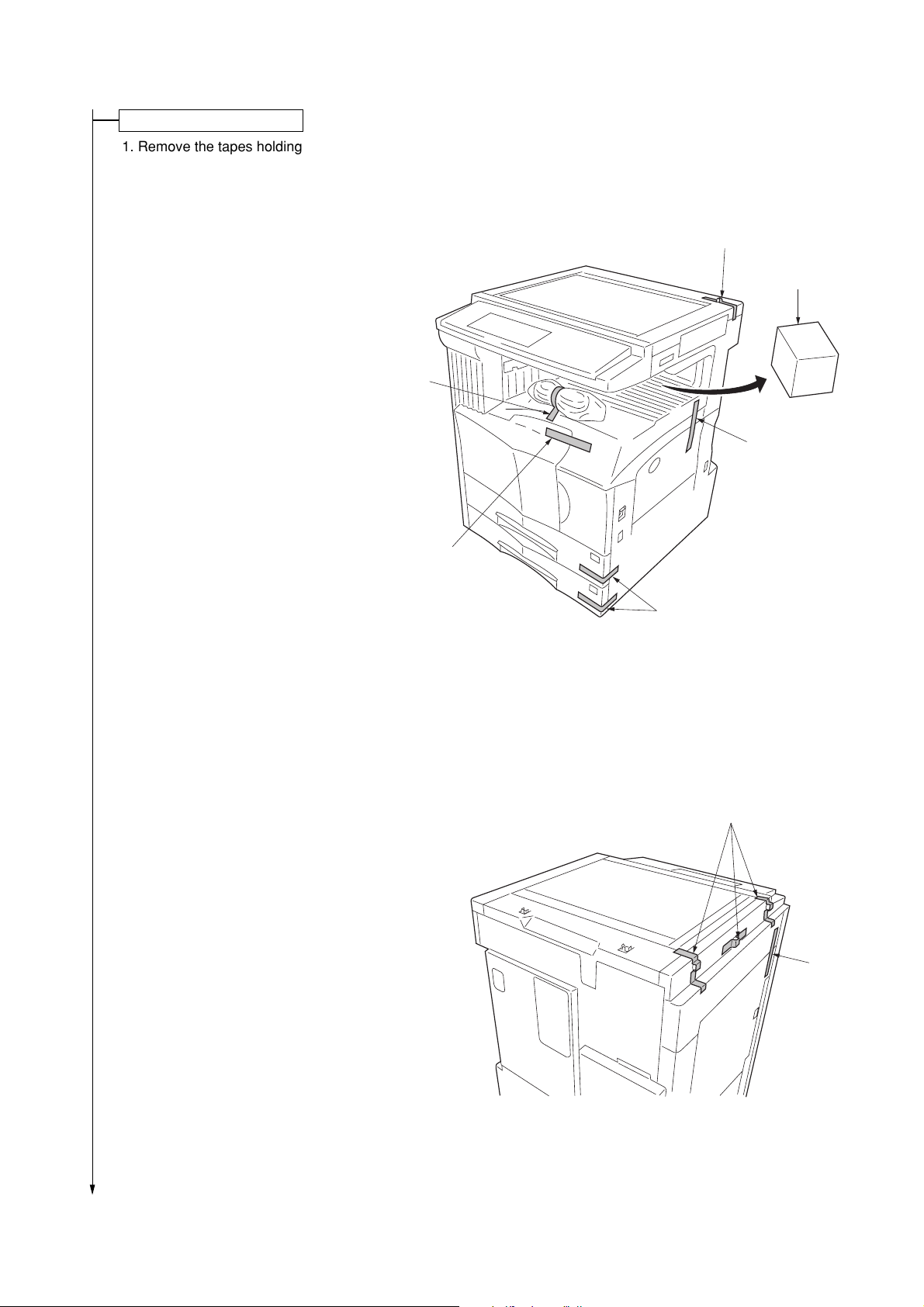
Remove the tapes and pad.
1. Remove the tapes holding the front cover,
bypass tray, drawers and original detection
switch.
2. Remove the tape and then remove the pad at the
eject section.
3. Remove the tape holding the power cord.
Tape
2FD/2FF/2FG-3.0
Tape
Pad
Tape
Tape
4. Remove the three tapes holding the pins for light
source units 1 and 2.
5. Remove the tape holding the conveying cover.
Tapes
Figure 1-3-3
Tapes
Tape
Figure 1-3-4
1-3-5
2FD/2FF/2FG-3.0
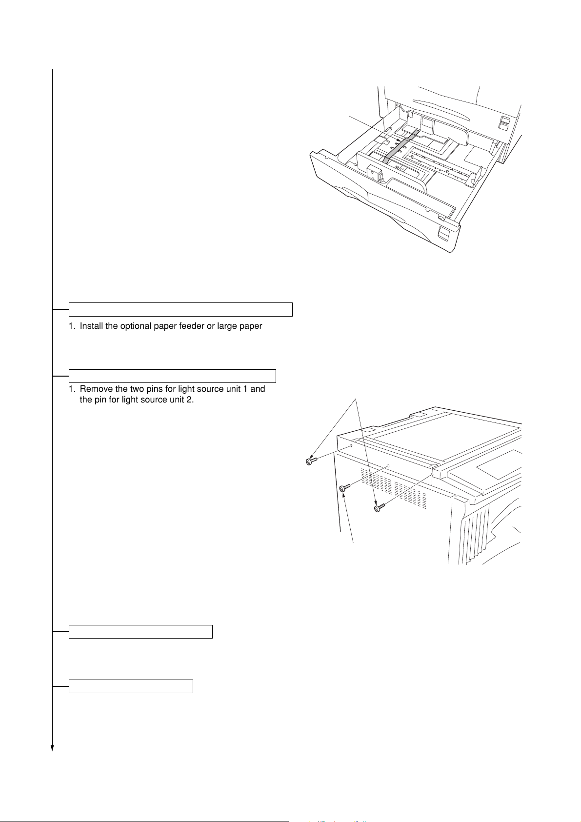
6. Pull upper and lower drawers out and remove the
tape holding each of the drawer lift.
*If necessary, please fix the cassette cursor with
the screws included in the machine box.
Install the optional paper feeder or large paper deck.
1. Install the optional paper feeder or large paper
deck as necessary (see page 1-3-13 to 1-3-21).
Tape
Figure 1-3-5
Remove the pins holding light source units 1 and 2.
1. Remove the two pins for light source unit 1 and
the pin for light source unit 2.
Light source unit 1 pins
Light source unit 2 pin
Install the original cover or the DP.
1. Install the original cover or DP (see page 1-3-33 when installing the DP).
Figure 1-3-6
Install other optional devices.
1. Install the optional devices (job separator, finisher, fax board, and/or printer board etc.) as necessary.
1-3-6
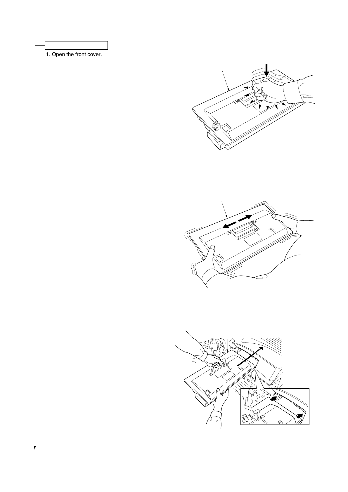
Install the toner container.
1. Open the front cover.
2. Tap the top of the toner container five to six
times.
3. Shake the toner container approximately 10
times in the horizontal direction to stir toner.
2FD/2FF/2FG-3.0
Toner container
Figure 1-3-7
Toner container
4. Gently push the toner container into the copier
along the rails.
*Push the container all the way into the copier until
it locks in place.
Figure 1-3-8
Toner container
Figure 1-3-9
1-3-7
 Loading...