

Page 1

KM-2550
SERVICE
MANUAL
Published in October 2004
842FT111
Revision 1
Page 2

CAUTION
Danger of explosion if battery is incorrectly replaced. Replace only with the same or equivalent
type recommended by the manufacturer. Dispose of used batteries according to the
manufacturer’s instructions.
CAUTION
Double-pole/neutral fusing.
Page 3

Revision history
Revision Date Replaced pages Remarks
1 15 October 2004 1-1-1, 2, 3, 1-3-1, 2, 4, 5, 1-4-2, 3, 4, 12, 14, 20, -
22, 23, 27, 28, 29, 30, 32, 34, 38, 44, 53, 54, 54-1,
1-5-18, 19, 20, 21, 22, 23, 24, 25, 1-6-16, 19, 21,
35, 36, 38, 2-4-7, 8, 9, 10
Page 4

This page is intentionally left blank.
Page 5

Safety precautions
This booklet provides safety warnings and precautions for our service personnel to ensure the safety of
their customers, their machines as well as themselves during maintenance activities. Service personnel
are advised to read this booklet carefully to familiarize themselves with the warnings and precautions
described here before engaging in maintenance activities.
Page 6
Safety warnings and precautions
Various symbols are used to protect our service personnel and customers from physical danger and
to prevent damage to their property. These symbols are described below:
DANGER: High risk of serious bodily injury or death may result from insufficient attention to or incorrect
compliance with warning messages using this symbol.
WARNING:Serious bodily injury or death may result from insufficient attention to or incorrect compliance
with warning messages using this symbol.
CAUTION: Bodily injury or damage to property may result from insufficient attention to or incorrect
compliance with warning messages using this symbol.
Symbols
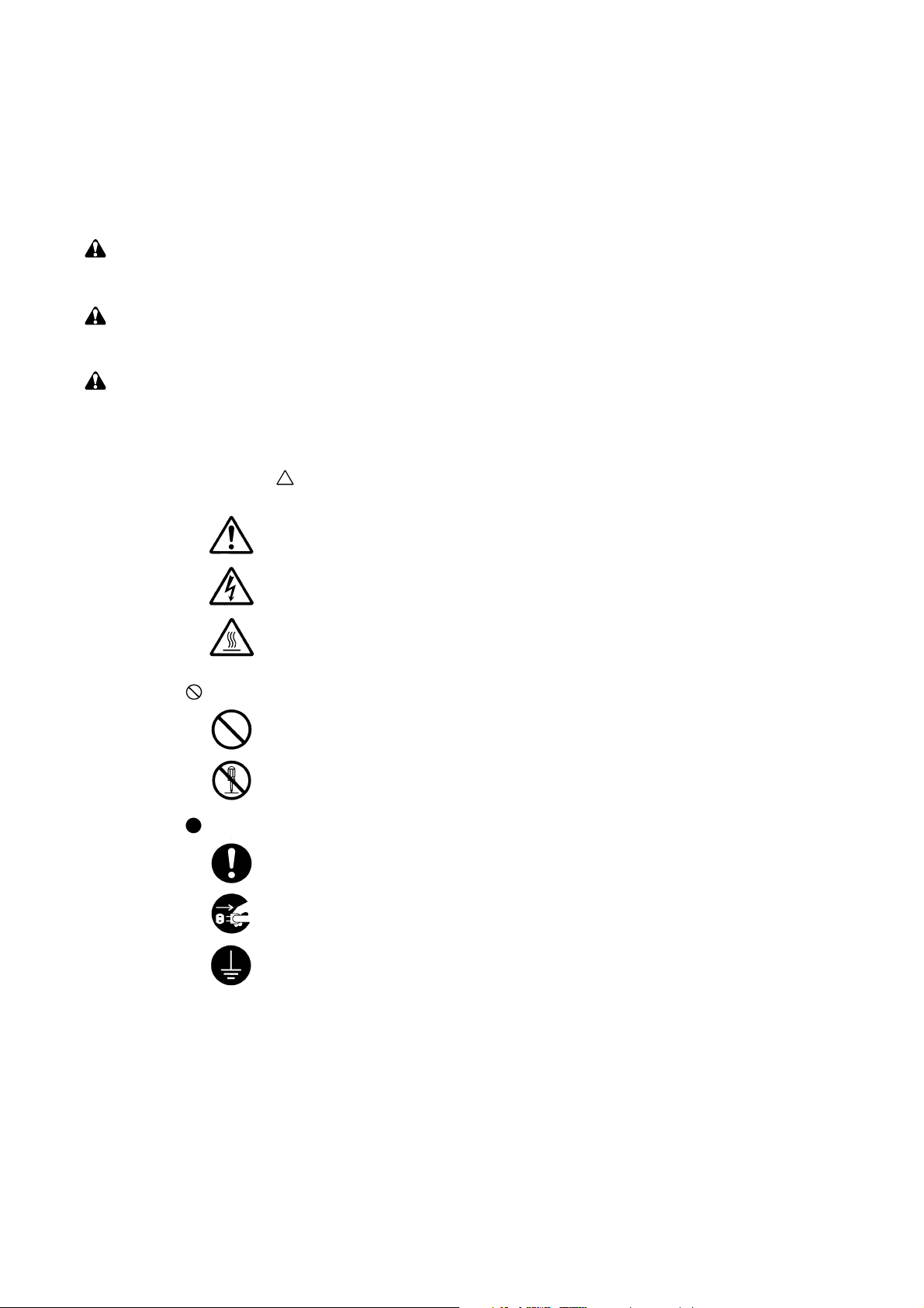
The triangle ( ) symbol indicates a warning including danger and caution. The specific point
of attention is shown inside the symbol.
General warning.
Warning of risk of electric shock.
Warning of high temperature.
indicates a prohibited action. The specific prohibition is shown inside the symbol.
General prohibited action.
Disassembly prohibited.
indicates that action is required. The specific action required is shown inside the symbol.
General action required.
Remove the power plug from the wall outlet.
Always ground the copier.
Page 7
1. Installation Precautions
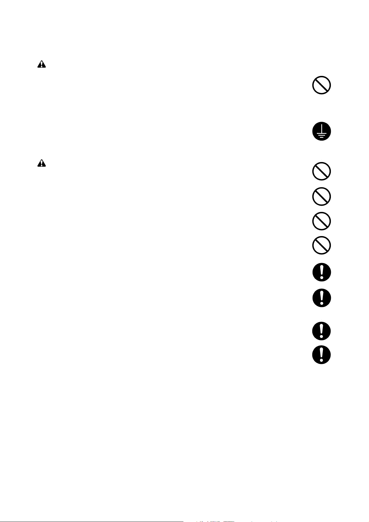
WARNING
• Do not use a power supply with a voltage other than that specified. Avoid multiple connections to
one outlet: they may cause fire or electric shock. When using an extension cable, always check
that it is adequate for the rated current. ............................................................................................
• Connect the ground wire to a suitable grounding point. Not grounding the copier may cause fire or
electric shock. Connecting the earth wire to an object not approved for the purpose may cause
explosion or electric shock. Never connect the ground cable to any of the following: gas pipes,
lightning rods, ground cables for telephone lines and water pipes or faucets not approved by the
proper authorities. .............................................................................................................................
CAUTION:
• Do not place the copier on an infirm or angled surface: the copier may tip over, causing injury. .....
• Do not install the copier in a humid or dusty place. This may cause fire or electric shock. ..............
• Do not install the copier near a radiator, heater, other heat source or near flammable material.
This may cause fire. ..........................................................................................................................
• Allow sufficient space around the copier to allow the ventilation grills to keep the machine as cool
as possible. Insufficient ventilation may cause heat buildup and poor copying performance. ..........
• Always handle the machine by the correct locations when moving it. ..............................................
• Always use anti-toppling and locking devices on copiers so equipped. Failure to do this may
cause the copier to move unexpectedly or topple, leading to injury..................................................
• Avoid inhaling toner or developer excessively. Protect the eyes. If toner or developer is
accidentally ingested, drink a lot of water to dilute it in the stomach and obtain medical attention
immediately. If it gets into the eyes, rinse immediately with copious amounts of water and obtain
medical attention. ..............................................................................................................................
• Advice customers that they must always follow the safety warnings and precautions in the copier’s
instruction handbook. ........................................................................................................................
Page 8
2. Precautions for Maintenance
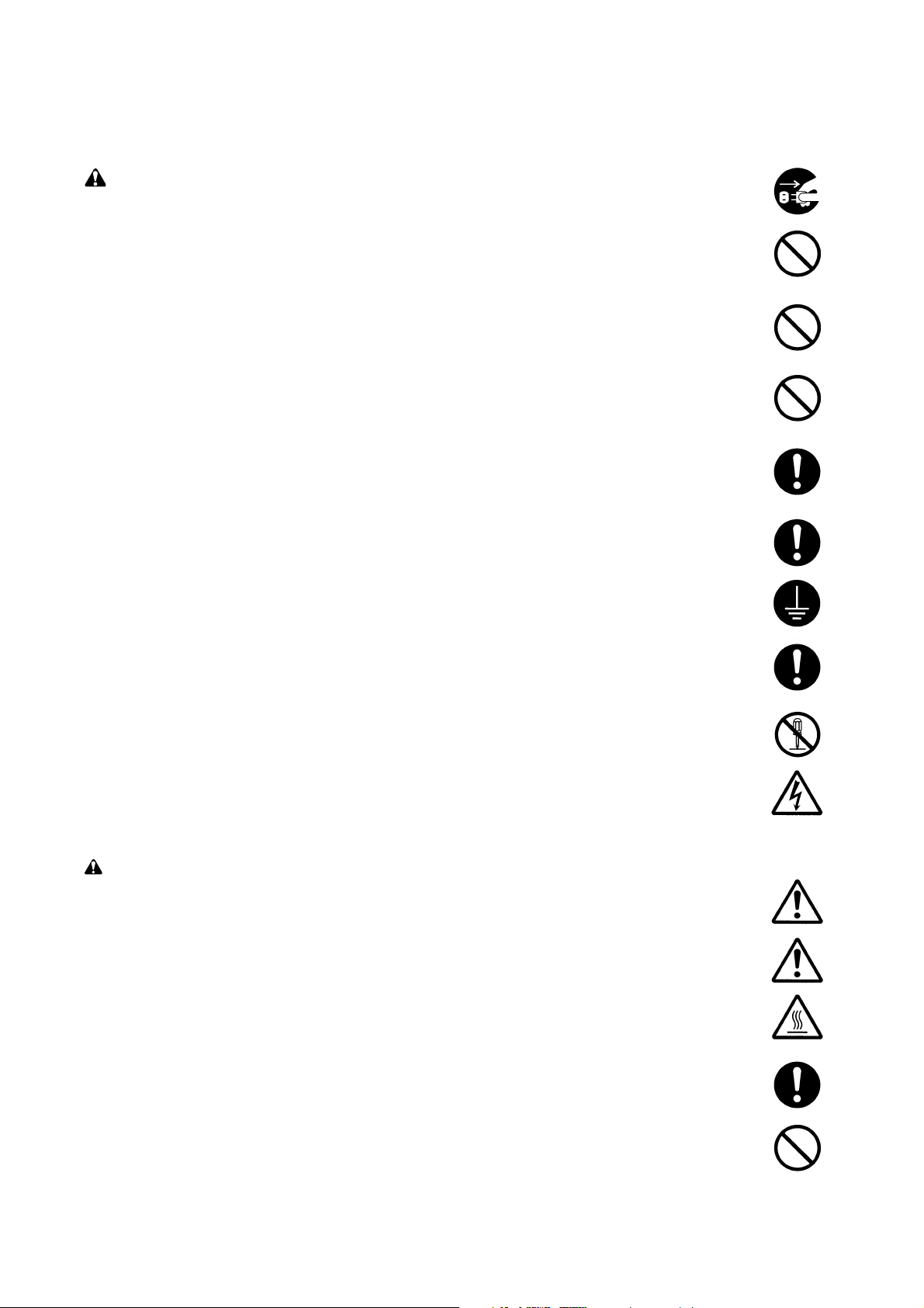
WARNING
• Always remove the power plug from the wall outlet before starting machine disassembly...............
• Always follow the procedures for maintenance described in the service manual and other related
brochures. .........................................................................................................................................
• Under no circumstances attempt to bypass or disable safety features including safety
mechanisms and protective circuits. .................................................................................................
• Always use parts having the correct specifications...........................................................................
• Always use the thermostat or thermal fuse specified in the service manual or other related
brochure when replacing them. Using a piece of wire, for example, could lead to fire or other
serious accident. ...............................................................................................................................
•When the service manual or other serious brochure specifies a distance or gap for installation of a
part, always use the correct scale and measure carefully. ...............................................................
• Always check that the copier is correctly connected to an outlet with a ground connection. ............
• Check that the power cable covering is free of damage. Check that the power plug is dust-free. If
it is dirty, clean it to remove the risk of fire or electric shock. ............................................................
• Never attempt to disassemble the optical unit in machines using lasers. Leaking laser light may
damage eyesight. ..............................................................................................................................
• Handle the charger sections with care. They are charged to high potentials and may cause
electric shock if handled improperly. .................................................................................................
CAUTION
•Wear safe clothing. If wearing loose clothing or accessories such as ties, make sure they are
safely secured so they will not be caught in rotating sections...........................................................
• Use utmost caution when working on a powered machine. Keep away from chains and belts. .......
• Handle the fixing section with care to avoid burns as it can be extremely hot. .................................
• Check that the fixing unit thermistor, heat and press rollers are clean. Dirt on them can cause
abnormally high temperatures...........................................................................................................
• Do not remove the ozone filter, if any, from the copier except for routine replacement....................
Page 9
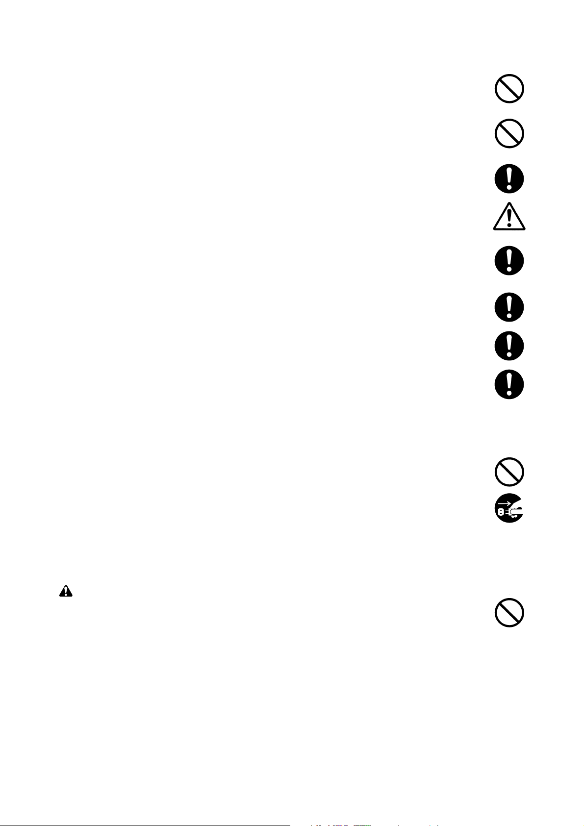
• Do not pull on the AC power cord or connector wires on high-voltage components when removing
them; always hold the plug itself. ......................................................................................................
• Do not route the power cable where it may be stood on or trapped. If necessary, protect it with a
cable cover or other appropriate item. ..............................................................................................
• Treat the ends of the wire carefully when installing a new charger wire to avoid electric leaks........
• Remove toner completely from electronic components. ...................................................................
• Run wire harnesses carefully so that wires will not be trapped or damaged. ...................................
• After maintenance, always check that all the parts, screws, connectors and wires that were
removed, have been refitted correctly. Special attention should be paid to any forgotten
connector, trapped wire and missing screws. ..................................................................................
• Check that all the caution labels that should be present on the machine according to the
instruction handbook are clean and not peeling. Replace with new ones if necessary. ...................
• Handle greases and solvents with care by following the instructions below: ....................................
· Use only a small amount of solvent at a time, being careful not to spill. Wipe spills off completely.
· Ventilate the room well while using grease or solvents.
· Allow applied solvents to evaporate completely before refitting the covers or turning the main
switch on.
· Always wash hands afterwards.
• Never dispose of toner or toner bottles in fire. Toner may cause sparks when exposed directly to
fire in a furnace, etc...........................................................................................................................
• Should smoke be seen coming from the copier, remove the power plug from the wall outlet
immediately. ......................................................................................................................................
3. Miscellaneous
WARNING
• Never attempt to heat the drum or expose it to any organic solvents such as alcohol, other than
the specified refiner; it may generate toxic gas. ................................................................................
Page 10

CONTENTS
1-1 Specifications
1-1-1 Specifications ....................................................................................................................................... 1-1-1
1-1-2 Parts names ......................................................................................................................................... 1-1-3
(1) MFP ................................................................................................................................................ 1-1-3
(2) Operation panel .............................................................................................................................. 1-1-4
1-1-3 Machine cross section .......................................................................................................................... 1-1-5
1-1-4 Drive system ........................................................................................................................................ 1-1-6
1-2 Handling Precautions
1-2-1 Drum .................................................................................................................................................... 1-2-1
1-2-2 Toner .................................................................................................................................................... 1-2-1
1-2-3 Installation environment ....................................................................................................................... 1-2-2
1-3 Installation
1-3-1 Unpacking and installation ................................................................................................................... 1-3-1
(1) Installation procedure ..................................................................................................................... 1-3-1
1-3-2 Setting initial copy modes .................................................................................................................... 1-3-6
1-3-3 Installing the paper feeder (option) ...................................................................................................... 1-3-7
1-3-4 Installing the DP (option) ...................................................................................................................... 1-3-9
1-3-5 Installing the duplex unit (option) ....................................................................................................... 1-3-13
1-3-6 Installing the drawer heater (option) ................................................................................................... 1-3-16
1-3-7 Installing the key counter (option) ...................................................................................................... 1-3-19
1-3-8 Installing the finisher (option) ............................................................................................................. 1-3-22
1-3-9 Installing the job separator (option) .................................................................................................... 1-3-30
1-3-10 Installing the fax system (option) ........................................................................................................ 1-3-35
1-3-11 Installing the scan system (option) ..................................................................................................... 1-3-43
1-3-12 Installing the hard disk (option) .......................................................................................................... 1-3-45
2FT-1
1-4 Maintenance Mode
1-4-1 Maintenance mode ............................................................................................................................... 1-4-1
(1) Executing a maintenance item ....................................................................................................... 1-4-1
(2) Maintenance modes item list .......................................................................................................... 1-4-2
(3) Contents of maintenance mode items ............................................................................................ 1-4-5
1-4-2 Management mode ............................................................................................................................ 1-4-55
(1) Using the management mode ...................................................................................................... 1-4-55
(2) Setting the job accounting ............................................................................................................ 1-4-56
(3) Copy default ................................................................................................................................. 1-4-57
(4) Machine default ............................................................................................................................ 1-4-59
(5) Bypass setting .............................................................................................................................. 1-4-61
(6) Checking the total counter and printing out the counter report ..................................................... 1-4-61
(7) Status report print out ................................................................................................................... 1-4-61
(8) Language selection function ......................................................................................................... 1-4-61
1-5 Troubleshooting
1-5-1 Paper misfeed detection ...................................................................................................................... 1-5-1
(1) Paper misfeed indication ................................................................................................................ 1-5-1
(2) Paper misfeed detection conditions ................................................................................................ 1-5-2
(3) Paper misfeeds ............................................................................................................................... 1-5-7
1-5-2 Self-diagnosis ..................................................................................................................................... 1-5-17
(1) Self-diagnostic function ................................................................................................................ 1-5-17
(2) Self-diagnostic codes ................................................................................................................... 1-5-18
1-5-3 Image formation problems ................................................................................................................. 1-5-26
(1) No image appears (entirely white). ............................................................................................... 1-5-27
(2) No image appears (entirely black). ............................................................................................... 1-5-27
(3) Image is too light. ......................................................................................................................... 1-5-28
1-1-1
Page 11

2FT
(4) Background is visible. ................................................................................................................... 1-5-28
(5) A white line appears longitudinally. .............................................................................................. 1-5-28
(6) A black line appears longitudinally. .............................................................................................. 1-5-29
(7) A black line appears laterally. ....................................................................................................... 1-5-29
(8) One side of the copy image is darker than the other. ................................................................... 1-5-29
(9) Black dots appear on the image. .................................................................................................. 1-5-30
(10) Image is blurred. ........................................................................................................................... 1-5-30
(11) The leading edge of the image is consistently misaligned with the original. ................................ 1-5-30
(12) The leading edge of the image is sporadically misaligned with the original. ................................ 1-5-31
(13) Paper creases. ............................................................................................................................. 1-5-31
(14) Offset occurs. ............................................................................................................................... 1-5-31
(15) Image is partly missing. ................................................................................................................ 1-5-32
(16) Fixing is poor. ............................................................................................................................... 1-5-32
(17) Image is out of focus. ................................................................................................................... 1-5-32
(18) Image center does not align with the original center. ................................................................... 1-5-33
1-5-4 Electrical problems ............................................................................................................................. 1-5-34
(1) The machine does not operate when the power switch is turned on. ........................................... 1-5-34
(2) The drive motor does not operate (C2000). ................................................................................. 1-5-34
(3) The registration motor does not operate. ..................................................................................... 1-5-34
(4) The exit motor does not operate. .................................................................................................. 1-5-34
(5) The scanner motor does not operate. .......................................................................................... 1-5-35
(6) Cooling fan motor 1 does not operate. ......................................................................................... 1-5-35
(7) Cooling fan motor 2 does not operate. ......................................................................................... 1-5-35
(8) Cooling fan motor 3 does not operate. ......................................................................................... 1-5-35
(9) Cooling fan motor 4 does not operate. ......................................................................................... 1-5-35
(10) Toner motor does not operate. ..................................................................................................... 1-5-35
(11) The drawer drive motor does not operate. ................................................................................... 1-5-35
(12) The paper feed clutch does not operate. ...................................................................................... 1-5-35
(13) The bypass paper feed clutch does not operate. ......................................................................... 1-5-36
(14) The drawer paper feed clutch does not operate. .......................................................................... 1-5-36
(15) The cleaning lamp does not turn on. ............................................................................................ 1-5-36
(16) The exposure lamp does not turn on. ........................................................................................... 1-5-36
(17) The exposure lamp does not turn off. ........................................................................................... 1-5-36
(18) The fixing heater does not turn on (C6000). ................................................................................. 1-5-36
(19) The fixing heater does not turn off. ............................................................................................... 1-5-36
(20) Main charging is not performed. ................................................................................................... 1-5-37
(21) Transfer charging is not performed. ............................................................................................. 1-5-37
(22) No developing bias is output. ....................................................................................................... 1-5-37
(23) The original size is not detected. .................................................................................................. 1-5-37
(24) The original size is not detected correctly. ................................................................................... 1-5-37
(25) The message requesting paper to be loaded is shown when paper is present in the drawer 1. .. 1-5-37
(26) The message requesting paper to be loaded is shown when paper is present in the drawer 2. .. 1-5-37
(27) The size of paper in the drawer 1 is not displayed correctly. ........................................................ 1-5-38
(28) The size of paper in the drawer 2 is not displayed correctly. ........................................................ 1-5-38
(29) A paper jam in the paper feed, paper conveying or fixing section is indicated when
the power switch is turned on. ...................................................................................................... 1-5-38
(30) The message requesting covers to be closed is displayed when the front cover and
left cover are closed. .................................................................................................................... 1-5-38
(31) Others. .......................................................................................................................................... 1-5-38
1-5-5 Mechanical problems ......................................................................................................................... 1-5-39
(1) No primary paper feed. ................................................................................................................. 1-5-39
(2) No secondary paper feed. ............................................................................................................ 1-5-39
(3) Skewed paper feed. ...................................................................................................................... 1-5-39
(4) The scanner does not travel. ........................................................................................................ 1-5-39
(5) Multiple sheets of paper are fed at one time.................................................................................. 1-5-39
(6) Paper jams. .................................................................................................................................. 1-5-39
(7) Toner drops on the paper conveying path. ................................................................................... 1-5-40
(8) Abnormal noise is heard. .............................................................................................................. 1-5-40
1-1-2
Page 12

1-6 Assembly and Disassembly
1-6-1 Precautions for assembly and disassembly ......................................................................................... 1-6-1
(1) Precautions ..................................................................................................................................... 1-6-1
(2) Running a maintenance item .......................................................................................................... 1-6-2
1-6-2 Paper feed section ............................................................................................................................... 1-6-3
(1) Detaching and refitting the separation pulley ................................................................................. 1-6-3
(2) Detaching and refitting the forwarding pulley and paper feed pulley .............................................. 1-6-5
(3) Detaching and refitting the feed roller ............................................................................................. 1-6-7
(4) Detaching and refitting the drawer separation pulley ..................................................................... 1-6-8
(5) Detaching and refitting the drawer forwarding pulley and drawer paper feed pulley ...................... 1-6-9
(6) Detaching and refitting the paper conveying unit ......................................................................... 1-6-11
(7) Detaching and refitting the bypass paper feed pulley and bypass separation pad ...................... 1-6-13
(8) Detaching and refitting the registration left roller .......................................................................... 1-6-15
(9) Detaching and refitting the registration cleaner ............................................................................ 1-6-15
(10) Adjustment after roller and clutch replacement ............................................................................ 1-6-16
(10-1) Adjusting the leading edge registration of image printing .................................................... 1-6-16
(10-2) Adjusting the leading edge registration for memory image printing ..................................... 1-6-17
(10-3) Adjusting the center line of image printing ........................................................................... 1-6-18
(10-4) Adjusting the trailing edge margin of image printing ............................................................ 1-6-19
(10-5) Adjusting the margins for printing ........................................................................................ 1-6-20
(10-6) Adjusting the amount of slack in the paper .......................................................................... 1-6-21
1-6-3 Optical section .................................................................................................................................... 1-6-22
(1) Detaching and refitting the exposure lamp ................................................................................... 1-6-22
(2) Detaching and refitting the scanner wires .................................................................................... 1-6-23
(2-1) Detaching the scanner wires ............................................................................................... 1-6-23
(2-2) Fitting the scanner wires ...................................................................................................... 1-6-25
(3) Detaching and refitting the ISU (reference) .................................................................................. 1-6-28
(4) Detaching and refitting the laser scanner unit .............................................................................. 1-6-29
(5) Adjusting the longitudinal squareness (reference) ....................................................................... 1-6-32
(6) Adjusting magnification of the scanner in the main scanning direction ........................................ 1-6-33
(7) Adjusting magnification of the scanner in the auxiliary scanning direction ................................... 1-6-34
(8) Adjusting the scanner leading edge registration ........................................................................... 1-6-35
(9) Adjusting the scanner center line ................................................................................................. 1-6-36
(10) Adjusting the margins for scanning an original on the contact glass ............................................ 1-6-37
1-6-4 Drum section ....................................................................................................................................... 1-6-38
(1) Detaching and refitting the drum unit ............................................................................................ 1-6-38
(2) Detaching and refitting the drum separation claws ....................................................................... 1-6-39
(3) Detaching and refitting the main charger unit ............................................................................... 1-6-40
1-6-5 Developing section .............................................................................................................................. 1-6-41
(1) Detaching and refitting the developing unit .................................................................................. 1-6-41
1-6-6 Transfer section .................................................................................................................................. 1-6-42
(1) Detaching and refitting the transfer roller ..................................................................................... 1-6-42
1-6-7 Fixing section ...................................................................................................................................... 1-6-43
(1) Detaching and refitting the fixing unit ........................................................................................... 1-6-43
(2) Detaching and refitting the press roller ......................................................................................... 1-6-45
(3) Detaching and refitting the fixing heater M and S ......................................................................... 1-6-46
(4) Detaching and refitting the heat roller separation claws ............................................................... 1-6-47
(5) Detaching and refitting the heat roller ........................................................................................... 1-6-48
(6) Detaching and refitting the fixing thermostat ................................................................................ 1-6-49
(7) Detaching and refitting the fixing thermistor ................................................................................. 1-6-49
(8) Adjusting the fixing unit height (adjusting lateral squareness) ...................................................... 1-6-50
2FT
1-7 Requirements on PCB Replacement
1-1-3
1-7-1 Upgrading the firmware on the main PCB ............................................................................................ 1-7-1
1-7-2 Upgrading the printer board firmware .................................................................................................. 1-7-2
1-7-3 Adjustment-free variable resisters (VR) ............................................................................................... 1-7-3
1-7-4 Remarks on engine PCB or main PCB replacement ........................................................................... 1-7-3
Page 13

2FT
2-1 Mechanical construction
2-1-1 Paper feed section ............................................................................................................................... 2-1-1
2-1-2 Optical section ...................................................................................................................................... 2-1-4
(1) Original scanning ............................................................................................................................ 2-1-5
(2) Image printing ................................................................................................................................. 2-1-6
2-1-3 Drum section ........................................................................................................................................ 2-1-8
2-1-4 Developing section ............................................................................................................................. 2-1-10
(1) Formation of magnetic brush ........................................................................................................ 2-1-11
(2) Single component developing system .......................................................................................... 2-1-12
2-1-5 Transfer and separation sections ....................................................................................................... 2-1-13
2-1-6 Fixing section ..................................................................................................................................... 2-1-15
(1) Fixing temperature system ........................................................................................................... 2-1-16
(2) Fixing temperature control based on ambient temperature .......................................................... 2-1-16
2-1-7 Exit and switchback sections ............................................................................................................. 2-1-17
2-1-8 Duplex section .................................................................................................................................... 2-1-18
(1) Paper conveying operation in duplex copying .............................................................................. 2-1-19
2-2 Electrical Parts Layout
2-2-1 Electrical parts layout ........................................................................................................................... 2-2-1
(1) PCBs .............................................................................................................................................. 2-2-1
(2) Switches and sensors ..................................................................................................................... 2-2-2
(3) Motors ............................................................................................................................................. 2-2-4
(4) Other electrical components ........................................................................................................... 2-2-5
2-3 Operation of the PCBs
2-3-1 Power source PCB ............................................................................................................................... 2-3-1
2-3-2 Main PCB ............................................................................................................................................. 2-3-4
2-3-3 Engine PCB .......................................................................................................................................... 2-3-8
2-3-4 Printer board PCB .............................................................................................................................. 2-3-15
2-3-5 Operation unit PCB ............................................................................................................................ 2-3-19
2-3-6 CCD PCB ........................................................................................................................................... 2-3-22
2-4 Appendixes
Timing chart No. 1 .......................................................................................................................................... 2-4-1
Timing chart No. 2 .......................................................................................................................................... 2-4-2
Timing chart No. 3 .......................................................................................................................................... 2-4-3
Timing chart No. 4 .......................................................................................................................................... 2-4-4
Chart of image adjustment procedures .......................................................................................................... 2-4-5
Maintenance parts list .................................................................................................................................... 2-4-8
Periodic maintenance procedures .................................................................................................................. 2-4-9
General wiring diagram ................................................................................................................................ 2-4-11
1-1-4
Page 14

1-1-1 Specifications
Type ............................................... Desktop
Copying system.............................. Indirect electrostatic system
Originals ......................................... Sheets, books and 3-dimensional objects (Maximum original size: A3/11" × 17")
Original feed system ...................... Fixed
Copy paper..................................... Paper weights
Drawer: 60 – 105 g/m
Bypass table: 45 – 160 g/m
Paper type
Drawer: Plain paper, recycled paper and colored paper
Bypass table: Plain paper, recycled paper, thin paper, thick paper and colored paper
Copying sizes ................................. Maximum: A3/11" × 17"
Minimum: A6R /5
Magnification ratios ........................ Manual mode: 25 – 200%, 1% increments
Copy speed .................................... At 100% magnification in copy mode:
A4: 25 copies/min.
A4R: 15 copies/min.
A3: 13 copies/min.
A5R: 12 copies/min.
A6R: 11 copies/min.
B5: 25 copies/min.
B5R: 15 copies/min.
B4 (257 × 364 mm): 13 copies/min.
1
11" × 8
8
/2": 25 copies/min.
1
/2" × 11": 15 copies/min.
11" × 17": 13 copies/min.
81/2" × 14": 13 copies/min.
First copy time ................................ 4.9 +_ 0.5 s or less (A4/11" × 8
Warm-up time................................. Less then 20 s (room temperature 23°C/73.4°F, 50% RH)
Time for recovery from low power mode: 10 s
Time for recovery from sleep mode: 20 s
Paper feed system ......................... Automatic feed
Capacity:
Drawers: 300 sheets (80 g/m
100 sheets (90 – 105 g/m
Manual feed
Capacity:
Bypass: 50 sheets (A4/11" × 8
25 sheets (A3, B4, 11" × 17", 8
Paper ejection system .................... In-machine ejection (face down)
Capacity: 250 sheets (80 g/m
Continuous copying........................ 1 – 999 sheets
Photoconductor ..............................a-Si drum (drum diameter 30 mm)
Charging system ............................ Single positive corona charging
Recording system .......................... Semiconductor laser
Developing system ......................... Single component developing system
Toner: magnetism toner
Toner replenishing: automatic from a toner container
Transfer system ............................. Transfer roller
Separation system ......................... Curvature separation and separation electrode
Fixing system ................................. Heat roller
Heat source: halogen heaters (120 V specifications: main 550 W, sub 400W/ 220-240
V specifications: main 600 W, sub 430 W)
Control temperature: 180°C/356°F (190°C/374°F on and after 6th sheet)
Abnormally high temperature protection device: 180°C/356°F thermostat
Fixing pressure: 44.1 N
Charge erasing system .................. Exposure by cleaning lamp
Cleaning system............................. Cleaning blade
Scanning system ............................ Flat bed scanning by CCD image sensor
Bitmap memory .............................. 35 MB (standard)
Image storage memory .................. 29 MB (standard)
Additional memory ......................... 16 MB, 32 MB, 64 MB and 128 MB
2
1
/2" × 81/2"
2
1
/2")
2
)
1
/2" or less)
2
)
2
)
1
/2" × 14")
2FT-1
1-1-1
Page 15

2FT-1
Resolution ...................................... 600 × 600 dpi
Light source.................................... Inert gas lamp
Dimensions .................................... 574 (W) × 593 (D) × 650 (H) mm
5
/8" (W) × 233/8" (D) × 259/16" (H)
22
Weight ............................................Approx. 47 kg/103.4 lbs
Floor requirements .........................827 (W) × 593 (D) mm (at the time of using bypass table)
5
/8" (W) × 233/8" (D) (at the time of using bypass table)
32
Functions........................................ Automatic paper selection, Image quality selection, Automatic sizing selection
function, zoom function, Duplex copy, Divided copy, Binding margin, Border width,
Aggregate copy, Sort copy, Eco-copy, Copy program and Section management mode
Power source ................................. 120 V AC, 60 Hz, 9.0 A
220 – 240 V AC, 50 Hz, 5.0 A
Options ........................................... Document processer, paper feeder, duplex unit, finisher, job separator, key counter,
fax system, network scanner, hard disk, additional memory and original cover
• Printer functions
Printing speed ................................ Same as copying speed
1
First print time ................................ Approx. 4.9 s (A4/11" × 8
/2")
Resolution ...................................... 300 dpi, 600 dpi, Fast 1200 mode
Memory .......................................... 64 MB (standard)
Additional memory: 32 MB, 64 MB, 128 MB and 256 MB
Hard disk: 340 MB, 512 MB and 1 GB
Applicable OS ................................ Microsoft Windows 95/98/Me/NT4.x/2000/XP
Apple Macintosh OS 9.x/OS X 10.x
UNIX/Linux
Interface ......................................... Parallel interface (based on IEEE1284)
Network interface
USB 2.0 (USB Hi-Speed)
Network interface card (option)
• Duplex unit
Type ............................................... Internal type
Copy paper..................................... Paper weights: 64 – 80 g/m
2
Paper type: Plain paper, recycled paper and colored paper
1
Paper sizes .................................... A3 – A5R/11" × 17" – 5
/2" × 81/2"
Power source ................................. Electrically connected to the MFP
Dimensions .................................... 368 (W) × 53 (D) × 180 (H) mm
1
/2" (W) × 21/16" (D) × 71/16" (H)
14
Weight ............................................Approx. 0.65 kg/1.43 lbs
1-1-2
Page 16
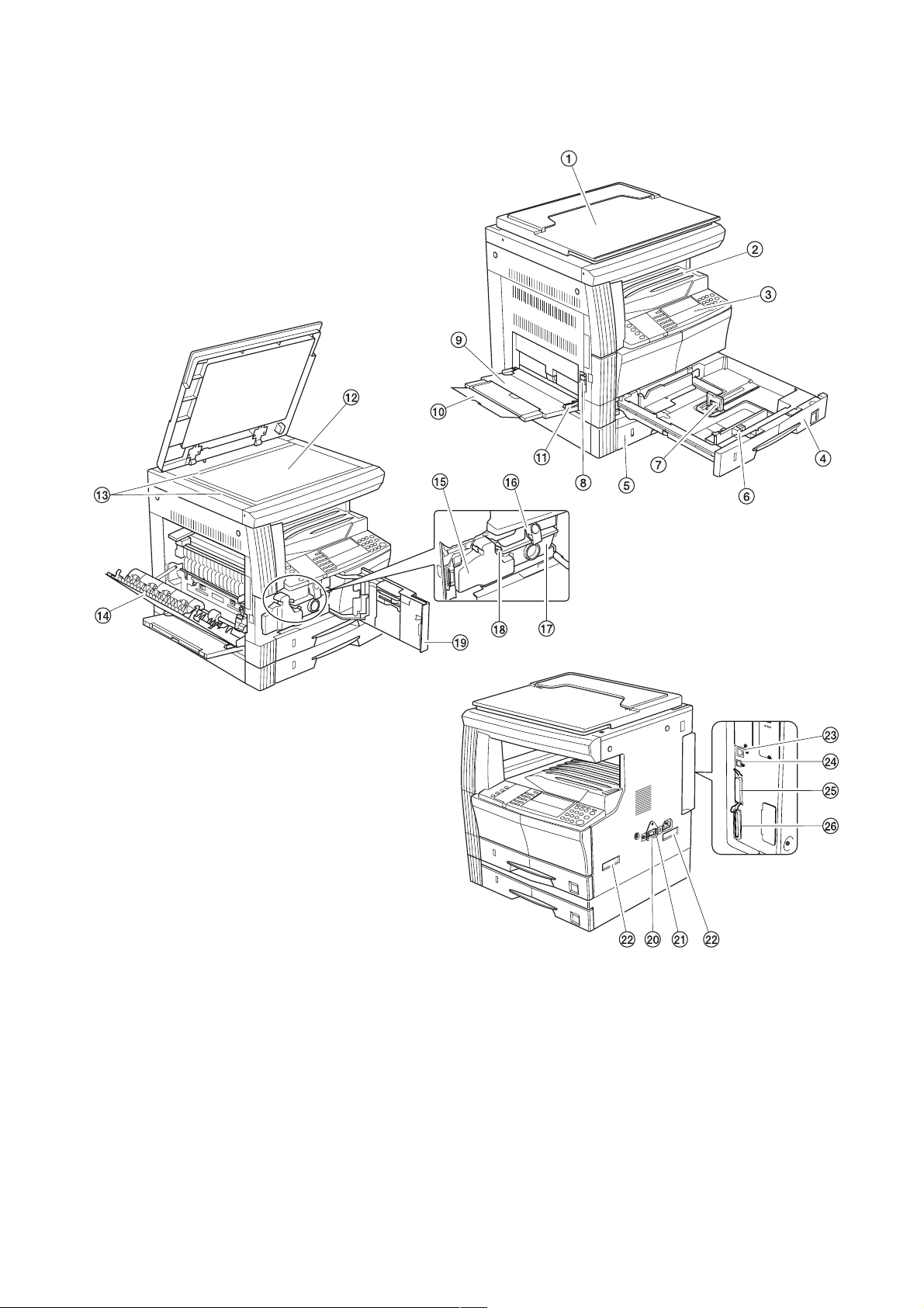
1-1-2 Parts names
(1) MFP
2FT-1
1 Original cover (optional)
2 Copy storage section
3 Operation panel
4 Drawer 1
5 Drawer 2
6 Width guide
7 Length guide
8 Left cover handle
9 Bypass tray
Figure 1-1-1
0 Support guide
! Slider
@ Contact glass
# Original size indicator plates
$ Left cover
% Waste toner box
^ Toner container release lever
& Toner container
* Cleaner rod
( Front cover
) Power switch
⁄ Power switch cover
¤ Handles for transport
‹ Network interface connector
› USB interface connector
fi Parallel interface connector
fl Memory card slot
1-1-3
Page 17
2FT
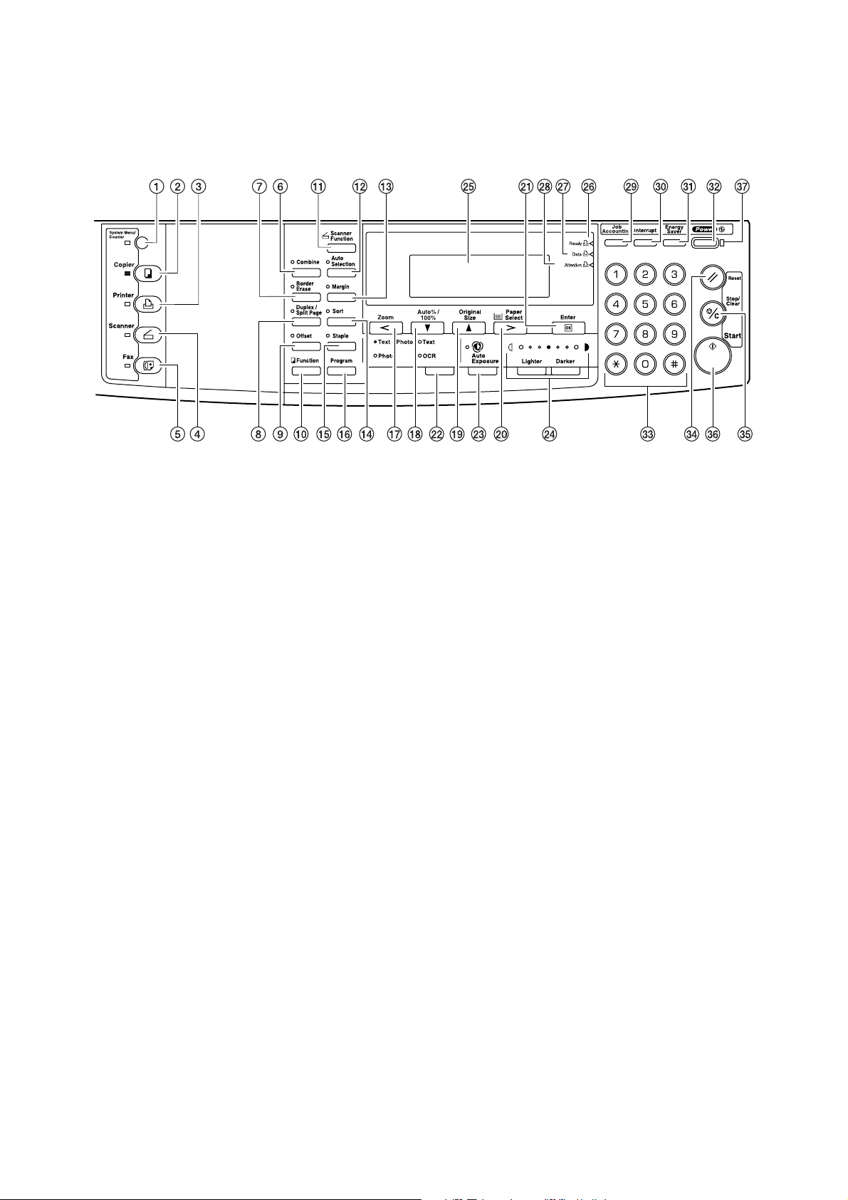
(2) Operation panel
1 System Menu/Counter key and indicator
2 Copier key and indicator
3 Printer key and indicator
4 Scanner key and indicator
5 Fax key and indicator
6 Combine key and indicator
7 Border Erase key and indicator
8 Duplex/Split Page key and indicator
9 Offset key and indicator
0 Function key
! Scanner Function key
@ Auto Selection key and indicator
# Margin key and indicator
$ Sort key and indicator
% Staple key and indicator
^ Program key
& Zoom key / Left cursor key
* Auto%/100% key / Down cursor key
( Original Size key / Up cursor key
Figure 1-1-2
) Paper Select key / Right cursor key
⁄ Enter key
¤ Image quality mode select key
‹ Auto Exposure key
› Lighter key / Darker key / exposure display
fi Message display
fl Ready indicator
‡ Data indicator
— Attention indicator
· Job Accounting key
‚ Interrupt key and indicator
ΠEnergy Saver key and indicator
„ Power key and indicator
´ Numeric keys
‰ Reset key
ˇ Stop/Clear key
Á Start key and indicator
¨ Main power indicator
1-1-4
Page 18
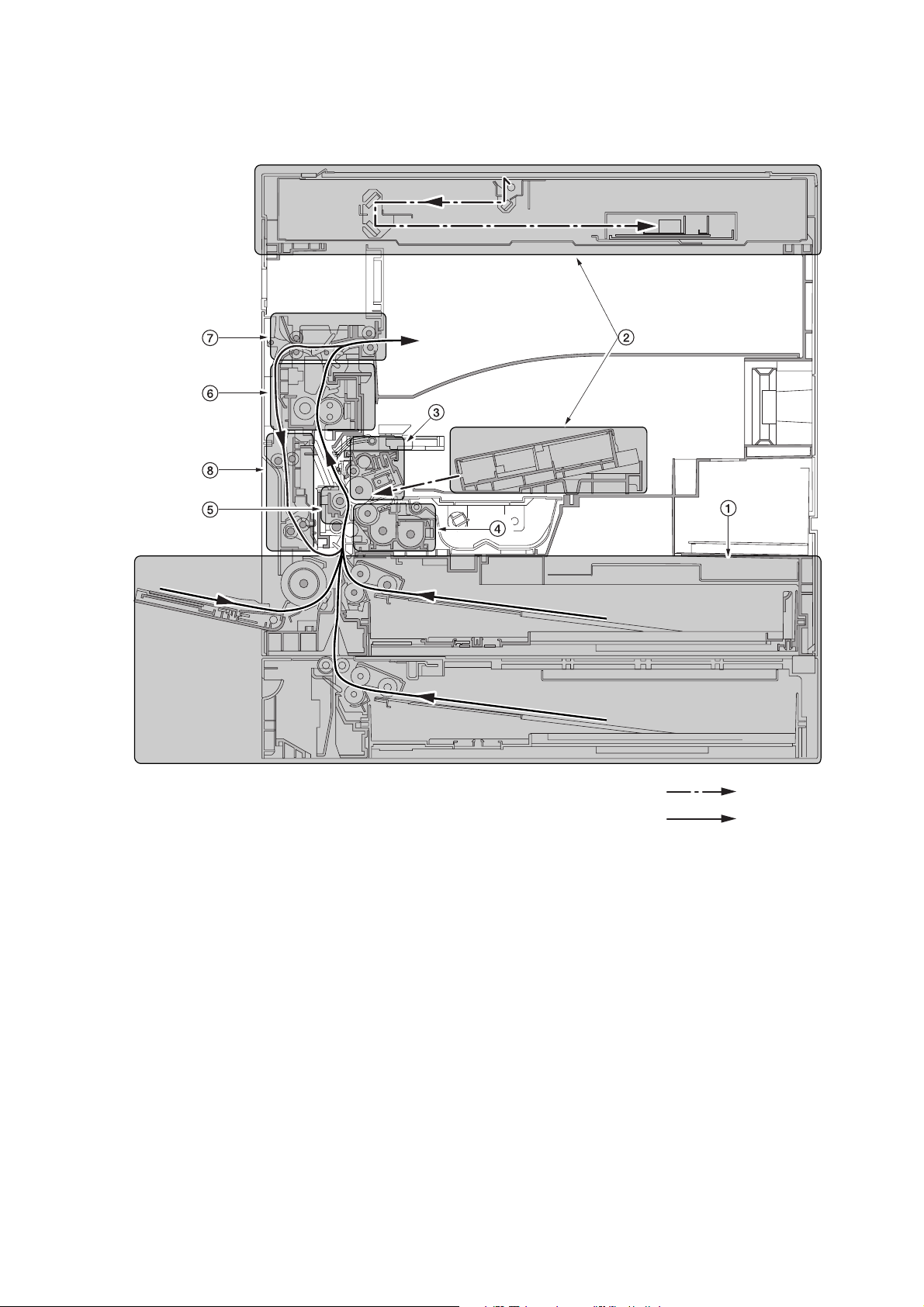
1-1-3 Machine cross section
p
2FT
Figure 1-1-3 Machine cross section
1 Paper feed section
2 Optical section
3 Drum section
4 Developing section
5 Transfer and separation section
6 Fixing section
7 Exit and switchback section
8 Duplex section
Light path
er path
Pa
1-1-5
Page 19

2FT
1-1-4 Drive system
1-1-6
1 Drive motor gear
2 Gear 136
3 Registration gear 51
4 Registration motor gear
5 Gear 32
6 Gear 25
7 Gear 25
8 Gear 20
9 Paper feed clutch gear
0 Gear 30
! Gear 31
@ Gear 25
# Gear 49
$ Gear 30/23
% Developing gear 25
Figure 1-1-4
^ Developing gear 26
& Gear 40
* Fixing joint gear 29
( Gear 31
) Gear 50
⁄ Gear 98/34
¤ Gear 50
‹ Gear 25
› Gear 40
fi Gear 30
fl Gear 50
‡ Gear 60
— Gear 32/23
· Exit motor gear
‚ Gear 43/20
Page 20

1-2-1 Drum
Note the following when handling or storing the drum.
• When removing the drum unit, never expose the drum surface to strong direct light.
• Keep the drum at an ambient temperature between –20°C/–4°F and 55°C/131°F and at a relative humidity not higher
than 90% RH. Avoid abrupt changes in temperature and humidity.
• Avoid exposure to any substance which is harmful to or may affect the quality of the drum.
• Do not touch the drum surface with any object. Should it be touched by hands or stained with oil, clean it.
1-2-2 Toner
Store the toner in a cool, dark place. Avoid direct light and high humidity.
2FT
1-2-1
Page 21
2FT
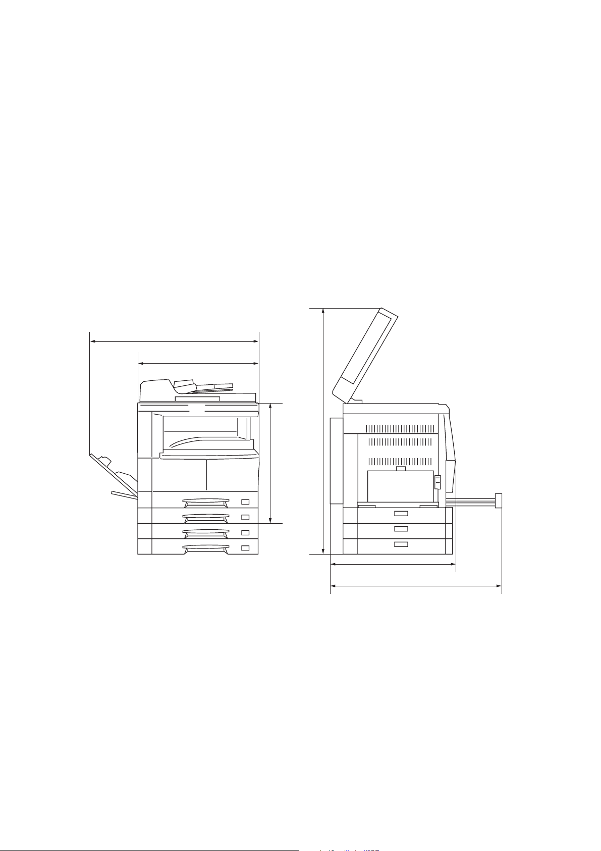
1-2-3 Installation environment
1. Temperature: 10 - 32.5°C/50 - 90.5°F
2. Humidity: 15 - 80%RH
3. Power supply: 120 V AC, 9.0 A
220 - 240 V AC, 5.0 A
4. Power source frequency: 50 Hz ±0.3%/60 Hz ±0.3%
5. Installation location
• Avoid direct sunlight or bright lighting. Ensure that the photoconductor will not be exposed to direct sunlight or other
strong light when removing paper jams.
• Avoid extremes of temperature and humidity, abrupt ambient temperature changes, and hot or cold air directed onto
the machine.
• Avoid dust and vibration.
• Choose a surface capable of supporting the weight of the machine.
• Place the machine on a level surface (maximum allowance inclination: 1° ).
• Avoid air-borne substances that may adversely affect the machine or degrade the photoconductor, such as
mercury, acidic of alkaline vapors, inorganic gasses, NOx, SOx gases and chlorine-based organic solvents.
• Select a room with good ventilation.
6. Allow sufficient access for proper operation and maintenance of the machine.
Machine front: 1000 mm/39
Machine right: 300 mm/11
3
/8" Machine rear: 100 mm/315/16"
13
/16" Machine left: 300 mm/1113/16"
d
a
f
c
b
e
a: 571 mm/221/2"
b: 603 mm/233/4"
c: 607 mm/237/8"
d: 1371.5 mm/54"
e: 1323 mm/52
f: 952.5 mm/371/2"
1
/16"
1-2-2
Figure 1-2-1 Installation dimensions
Page 22
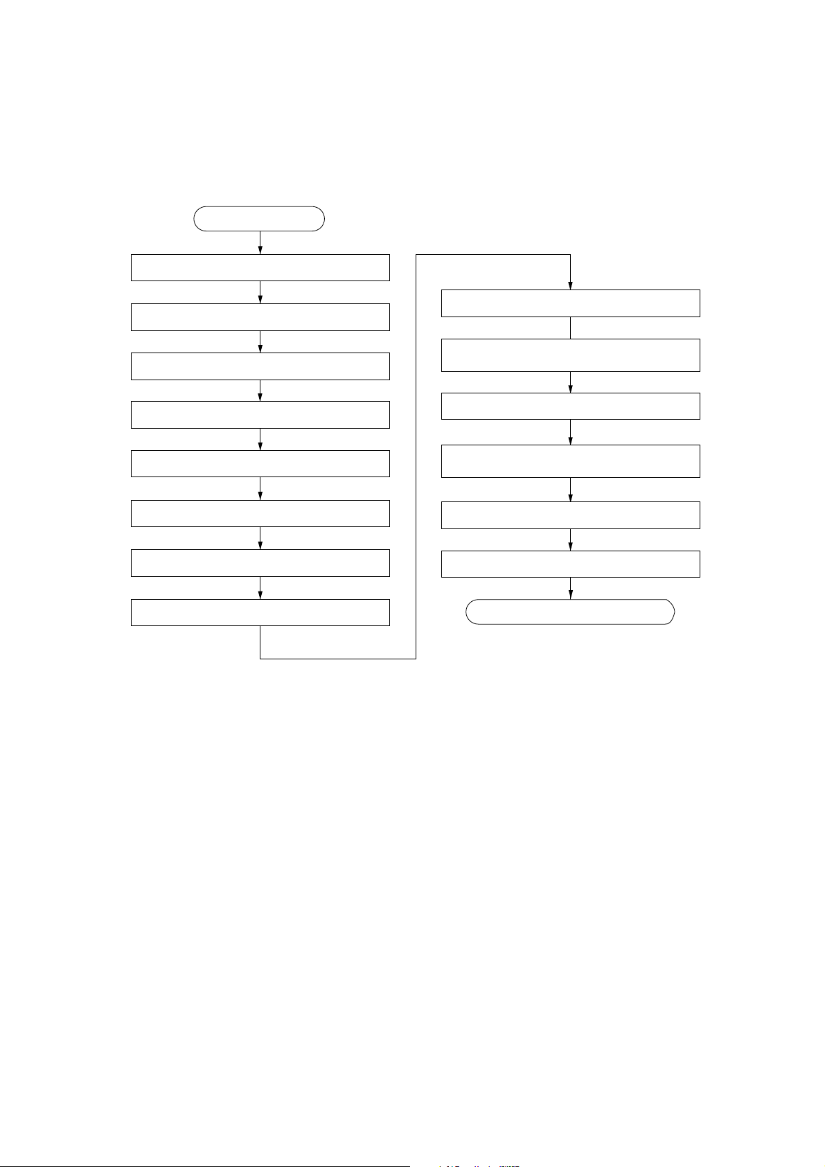
1-3-1 Unpacking and installation
(1) Installation procedure
Start
Unpack.
Install the optional paper feeder.
Remove the tapes and pins.
2FT-1
Connect the power cord.
Installing the toner
(maintenance item U130).
Install the optional original cover or DP.
Install the optional duplex unit.
Install the optional finisher or job separator.
Install the toner container.
Connect the connector of the drawer heater.
Load paper.
Output an own-status report
(maintenance item U000).
Exit maintenance mode.
Make test copies.
End of installation.
1-3-1
Page 23
2FT-1
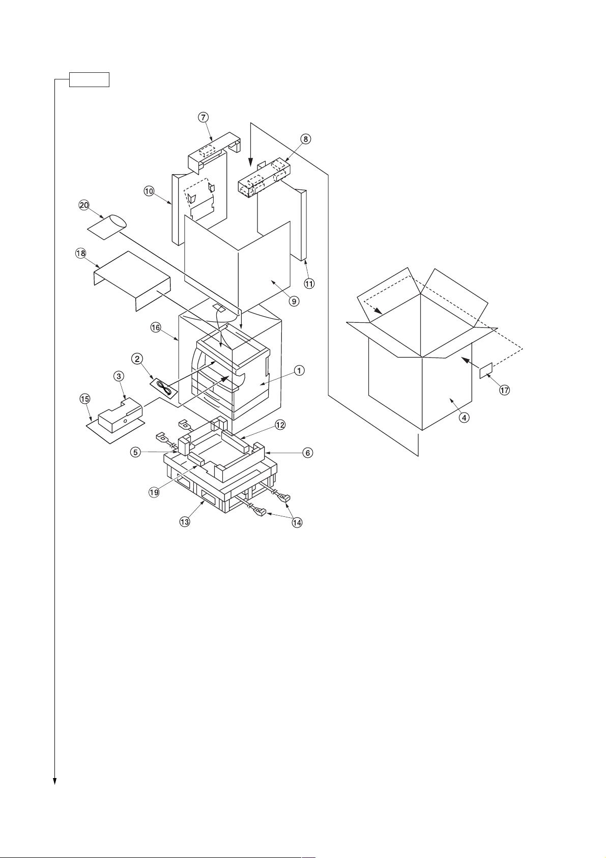
Unpack.
1 MFP
2 Power cord
3 Toner container
4 Outer case
5 Lower left pad
6 Lower right pad
7 Upper left pad
8 Upper right pad
9 Inner frame
* Place the machine on a level surface.
1-3-2
Figure 1-3-1 Unpacking
0 Left spacer
! Rear spacer
@ Rear pad
# Skid
$ Belt
% Eject sheet
^ Machine cover
& Bar code labels
* Top sheet
( Front pad
) Operation guide
Cassette size sheet
Paper protection bag
Error code label
Inspection report
Page 24
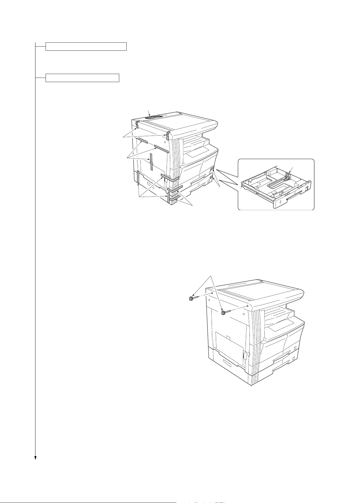
Install the optional paper feeder.
Tapes
Tapes
Tape
Tapes
Tapes
Tapes
Tape
1. Install the optional paper feeder as necessary
(see page 1-3-7 to 1-3-8).
Remove the tapes and pins.
1. Remove the fifteen tapes.
2FT
2. Remove the two pins for light source unit.
Figure 1-3-2
Pins
Figure 1-3-3
1-3-3
Page 25
2FT-1
Install the optional original cover or DP.
1. Install the optional original cover or DP (see pages 1-3-9 to 1-3-12 when installing the DP).
Install the optional duplex unit.
1. Install the optional duplex unit as necessary (see pages 1-3-13 to 1-3-15).
Install the optional finisher or job separator.
1. Install the optional finisher or job separator as necessary (see pages 1-3-22 to 1-3-34).
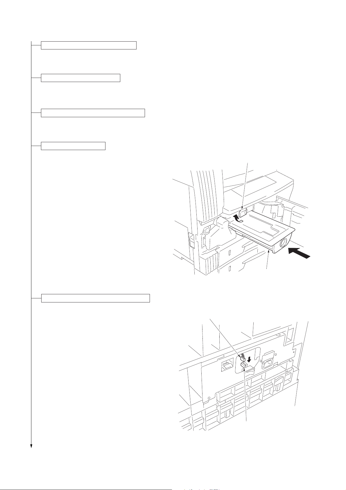
Install the toner container.
1. Open the front cover.
2. Tap the top of the toner container five to six
times.
3. Shake the toner container approximately 10 times
in the horizontal direction to stir toner.
4. Turn the toner container release lever and gently
push the toner container into the MFP.
* Push the container all the way into the MFP until
it locks in place.
5. Restore the toner container release lever.
6. Close the front cover.
Connect the connector of the drawer heater.
* Connect according to need.
1. Remove the right cover.
2. Connect the connector of the drawer heater to
YC7 of the power source PCB.
3. Refit the right cover.
Toner container release lever
Toner container
Figure 1-3-4-1
Connector of the drawer heater
1-3-4
YC7
Figure 1-3-4-2
Page 26

Connect the power cord.
1. Connect the power cord to the connector on the MFP.
2. Insert the power plug into the wall outlet and turn the power switch on.
Installing the toner (maintenance item U130).
1. Enter the maintenance mode by entering “10871087” using the numeric keys.
2. Enter “130” using the numeric keys and press the start key.
3. Select the “EXECUTE” using the up/down cursor keys.
4. Press the start key to execute the maintenance item.
Installation of toner starts and time (minutes) is indicated until the installation ends.
5. When the installation is complete, “FINISHED” will be displayed if the installation is successful or “NG” will be
displayed if it has failed.
If “NG” is displayed, check to see if the toner container contains toner and to see if the toner container sensor
malfunctions and then try again.
6. Press the stop/clear key.
Load paper.
1. Load paper in the drawer.
Output an own-status report (maintenance item U000).
1. Enter “000” using the numeric keys and press the
start key.
2. Select “MAINTENANCE” and press the start key
to output a list of the current settings of the
maintenance items.
3. Press the stop/clear key.
2FT-1
Exit maintenance mode.
1. Enter “001” using the numeric keys and press the
start key.
The machine exits the maintenance mode.
Make test copies.
1. Place an original and make test copies.
Set A3/11" x 17" paper on drawer 2 and run the maintenance item U113 (Performing drum refresh operation) if a
faulty image (black lines, etc.) occurs.
End of installation.
1-3-5
Page 27

2FT
1-3-2 Setting initial copy modes
Factory settings are as follows:
Maintenance
item No.
U253
U254
U258
U260
U264
U277
U326
U342
U343
U344
Contents
Switching between double and single counts
Turning auto start function on/off
Switching copy operation at toner
empty detection
Changing the copy count timing
Setting the display order of the date
Setting auto aplication change time
Setting the black line cleaning indication
Setting the ejection restriction
Switching between duplex/simplex copy mode
Setting preheat/energy saver mode
Factory setting
Double count
ON
SINGLE MODE
After ejection
Month/Day/Year (Inch specifications)
Day/Month/Year (Inch specifications)
30
ON
ON
OFF
ENERGY STAR
1-3-6
Page 28
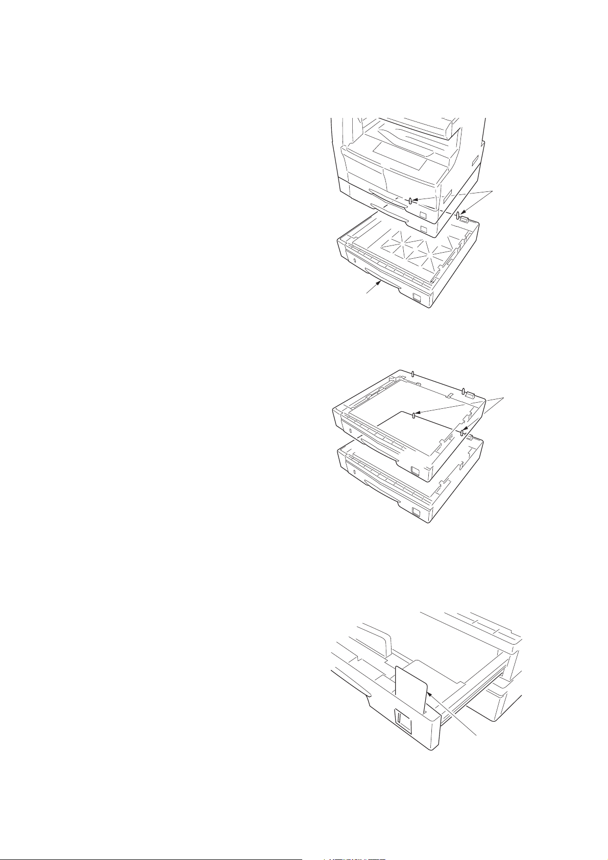
1-3-3 Installing the paper feeder (option)
<Procedure>
1. Place the MFP on the paper feeder by aligning the
positioning insertion sections of the MFP with the
positioning pins at the rear part of the paper feeder.
* When placing the MFP, take care not to hit the
MFP against the drawer, the pins or ground plate of
the paper feeder.
2FT
Positioning pins
Paper feeder
Figure 1-3-5
For stacking paper feeders for use:
Stack a paper feeder on another paper feeder by
aligning the positioning insertion sections of the first
paper feeder with the positioning pins at the rear
part of the second paper feeder.
(Two paper feeders can be added.)
2. If a type of paper that is not included in the
specifications for the standard sheet cassette size is
used, replace the cassette size sheet indication with
the supplied one.
3. Insert the MFP power plug into the wall outlet and
turn the power switch on.
Load paper in the drawer and make test copies to
check the operation.
Positioning
pins
Figure 1-3-6
Figure 1-3-7
Cassette size
sheet indication
1-3-7
Page 29

2FT
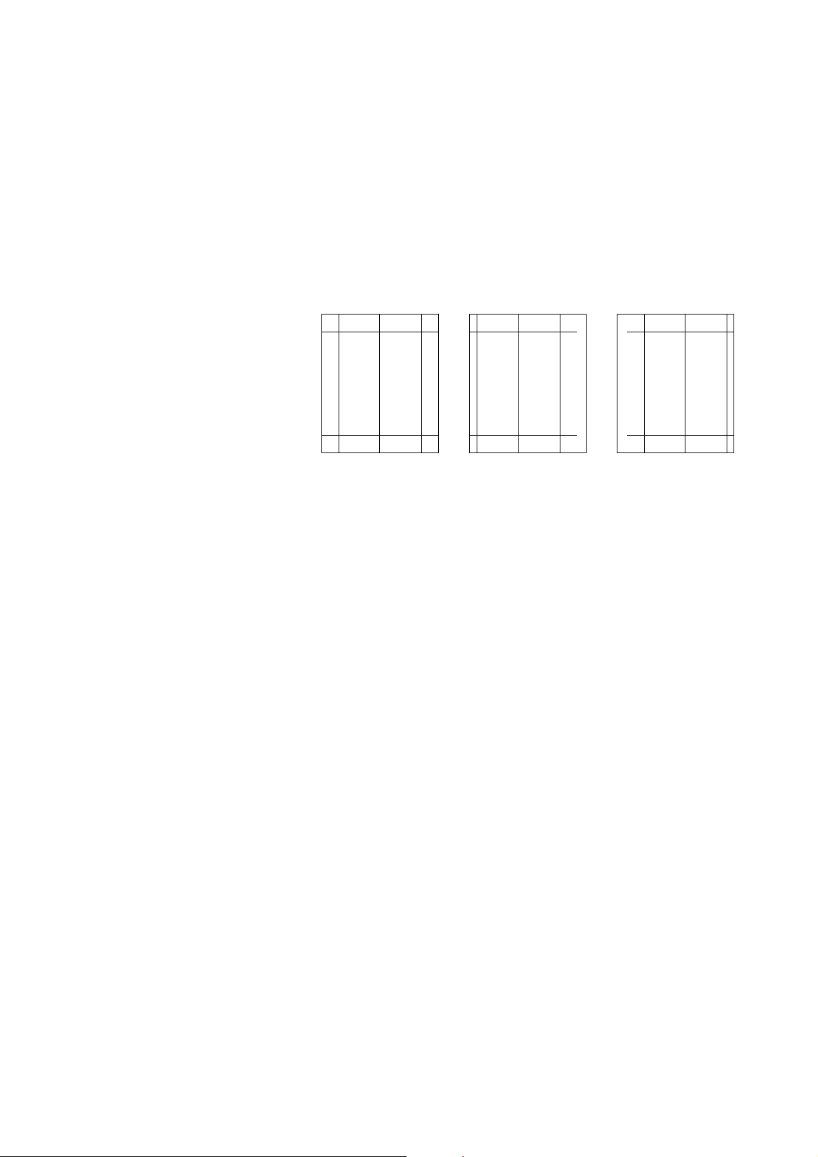
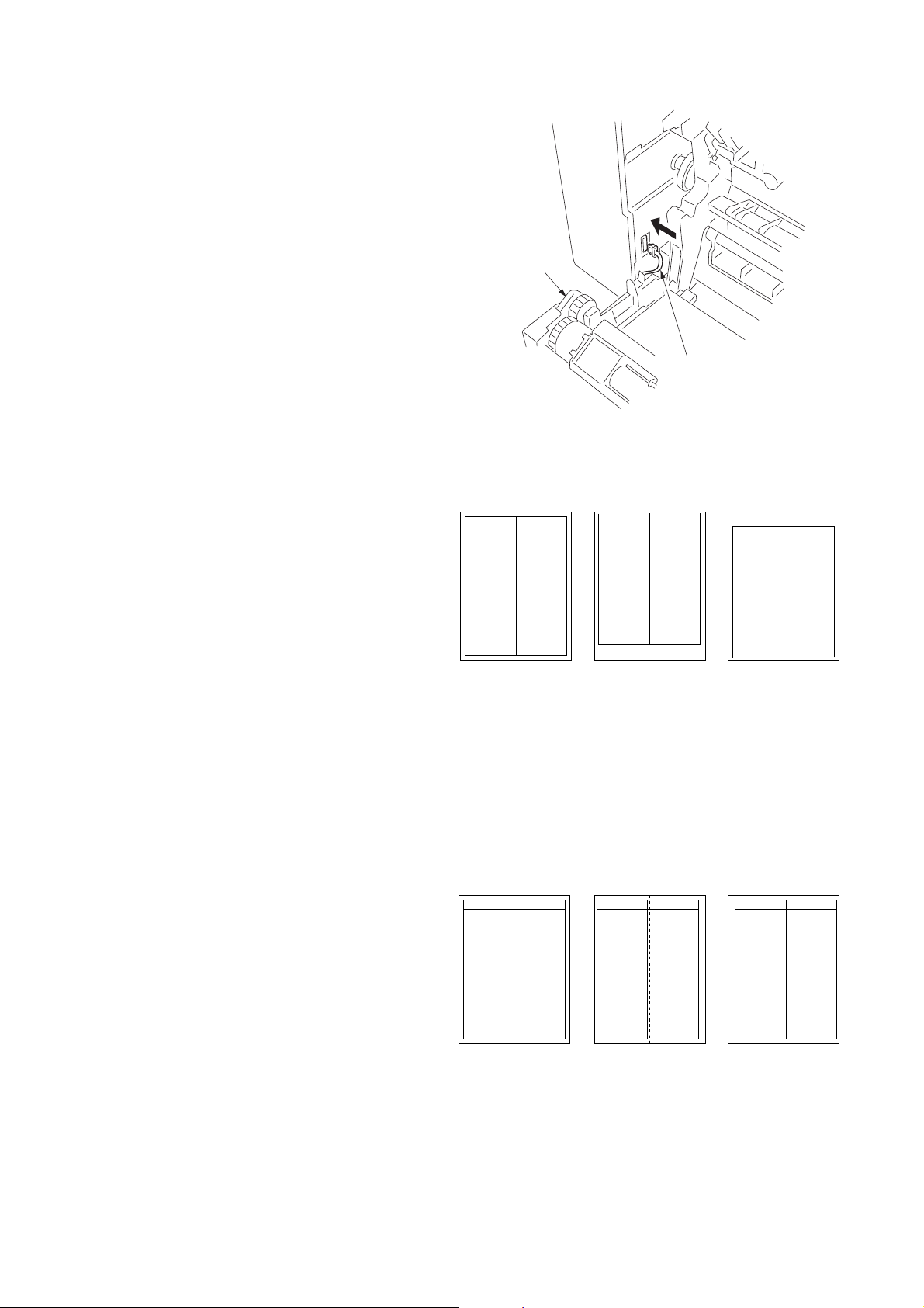
Adjusting the leading edge timing
1. Run maintenance mode 034.
Select ADJ, RCL ON TIMING and press the start key.
First optional cassette: Select RCL T1.
Second optional cassette: Select RCL T2.
Third optional cassette: Select RCL T3.
For models equipped with two standard cassettes, adjust only RCL T2 and RCL T3.
Press the Interrupt key to output the test pattern and check the image. If an adequate image cannot be obtained,
carry out the following adjustment.
2. If a test pattern a is obtained, increase the adjustment value.
If a test pattern b is obtained, decrease the adjustment value.
Setting range: -5.0 - +10.0
Changing the value by one moves the leading edge by 0.1 mm.
3. Output the test pattern again.
4. Repeat steps 2 and 3 until an adequate image is obtained.
Adequate image Test pattern a Test pattern b
Figure 1-3-8
Adjusting the center line
1. Run maintenance mode 034.
Select ADJ, LSU OUT TIMING and press the start key.
First optional cassette: Select LSU T1.
Second optional cassette: Select LSU T2.
Third optional cassette: Select LSU T3.
For models equipped with two standard cassettes, adjust only LSU T2 and LSU T3.
Press the Interrupt key to output the test pattern and check the image. If an adequate image cannot be obtained,
carry out the following adjustment.
2. If a test pattern a is obtained, increase the adjustment value.
If a test pattern b is obtained, decrease the adjustment value.
Setting range: -7.0 - +10.0
Changing the value by one moves the center line by 0.1 mm.
3. Output the test pattern again.
4. Repeat steps 2 and 3 until an adequate image is obtained.
1-3-8
Adequate image Test pattern a Test pattern b
Figure 1-3-9
Page 30
1-3-4 Installing the DP (option)
<Procedure>
1. Remove the original holder and remove the two
screws from the rear top cover.
2. Pass the two pins through the screw holes of the rear
top cover and attach them to the lower frame.
2FT
Pin
Screw
Pin
Screw
Figure 1-3-10
3. Place the DP on the MFP by fitting the pins into the
holes at the hinge sections of the DP and sliding
them toward the front side.
4. Secure the DP with the two TP Taptite chromate
screws M4 × 10 and the two screws that have been
removed in step 1.
Pin
Hole Hole
TP Taptite
chromate
screw M4 × 10
DP
Figure 1-3-11
TP Taptite
chromate
screw M4 × 10
Screw
Pin
Screw
DP
Figure 1-3-12
1-3-9
Page 31

2FT
15mm15mm
15mm
15mm
Lines
Lines
Center line
Original
5. Close the DP, fit the fixing fitting from the rear side of
the right hinge, and secure it with the two bronze TP
screws M3 x 06.
6. Connect the cable of the DP to the MFP.
* Be sure to tighten the fixing screws on both side of
the connector.
7. Clean the pasting position for the caution label with
alcohol.
Paste the caution label that corresponds to the
language according to the destination to the DP.
Cable
Fixing fitting
Bronze TP screws M3 x 06
Figure 1-3-13
Caution label
[Operation check]
1. Prepare an original on which 4 lines are drawn 15
mm from the edges and the center line is drawn.
2. Set the original on the DP and make a test copy to
check the copy image.
At this time, set the paper guide for the original table
and drawer to the paper size to be used.
3. If the copy image does not match the original image,
carry out the following adjustments in maintenance
mode.
• Maintenance mode 070 (sub-scan line adjustment)
• Maintenance mode 071 (leading edge timing
adjustment)
• Maintenance mode 072 (center line adjustment)
1-3-10
Figure 1-3-14
Figure 1-3-15
Page 32

Maintenance mode 070 (sub-scan line adjustment)
1. Run maintenance mode 070.
Select CONVEY SPEED1.
(For adjustment of the back side in duplex copying, select CONVEY SPEED2.)
Set originals in the original tray and press the interrupt key. Make a test copy to check the image.
If an adequate image cannot be obtained, carry out the following adjustment.
2. For copy example a: decrease the value.
For copy example b: increase the value.
Setting range: -25 - +25
Changing the value by one changes the sub-scan line by 0.1%.
A smaller setting value makes the copy image shorter. A larger value makes the image longer.
Original Copy example a Copy example b
2FT
Figure 1-3-16
Maintenance mode 071 (leading edge timing adjustment)
1. Run maintenance mode 071.
Select LEAD1.
(For adjustment of the back side in duplex copying, select LEAD2.)
Set originals in the original tray and press the interrupt key. Make a test copy to check the image.
If an adequate image cannot be obtained, carry out the following adjustment.
2. For copy example a: increase the value.
For copy example b: decrease the value.
Setting range: -32 - +22
Changing the value by one moves the leading edge by 0.2 mm.
The larger the value, the later the image scan start timing.
The smaller the value, the earlier the image scan start timing.
Original Copy example a Copy example b
Figure 1-3-17
1-3-11
Page 33
2FT
Maintenance mode 072 (center line adjustment)
1. Run maintenance mode 072.
Select 1sided.
(For adjustment of the front side in duplex copying, select 2sided front. For adjustment of the back side, select 2sided
back.)
Set originals in the original tray and press the Interrupt key. Make a test copy to check the image.
If an adequate image cannot be obtained, carry out the following adjustment.
2. For copy example a: increase the value.
For copy example b: decrease the value.
Setting range: -39 - +39
Changing the value by one moves the center line by 0.1 mm.
The larger the value, the center of the image moves toward the right.
The smaller the value, the center of the image moves toward the left.
Original Copy example a Copy example b
Figure 1-3-18
1-3-12
Page 34
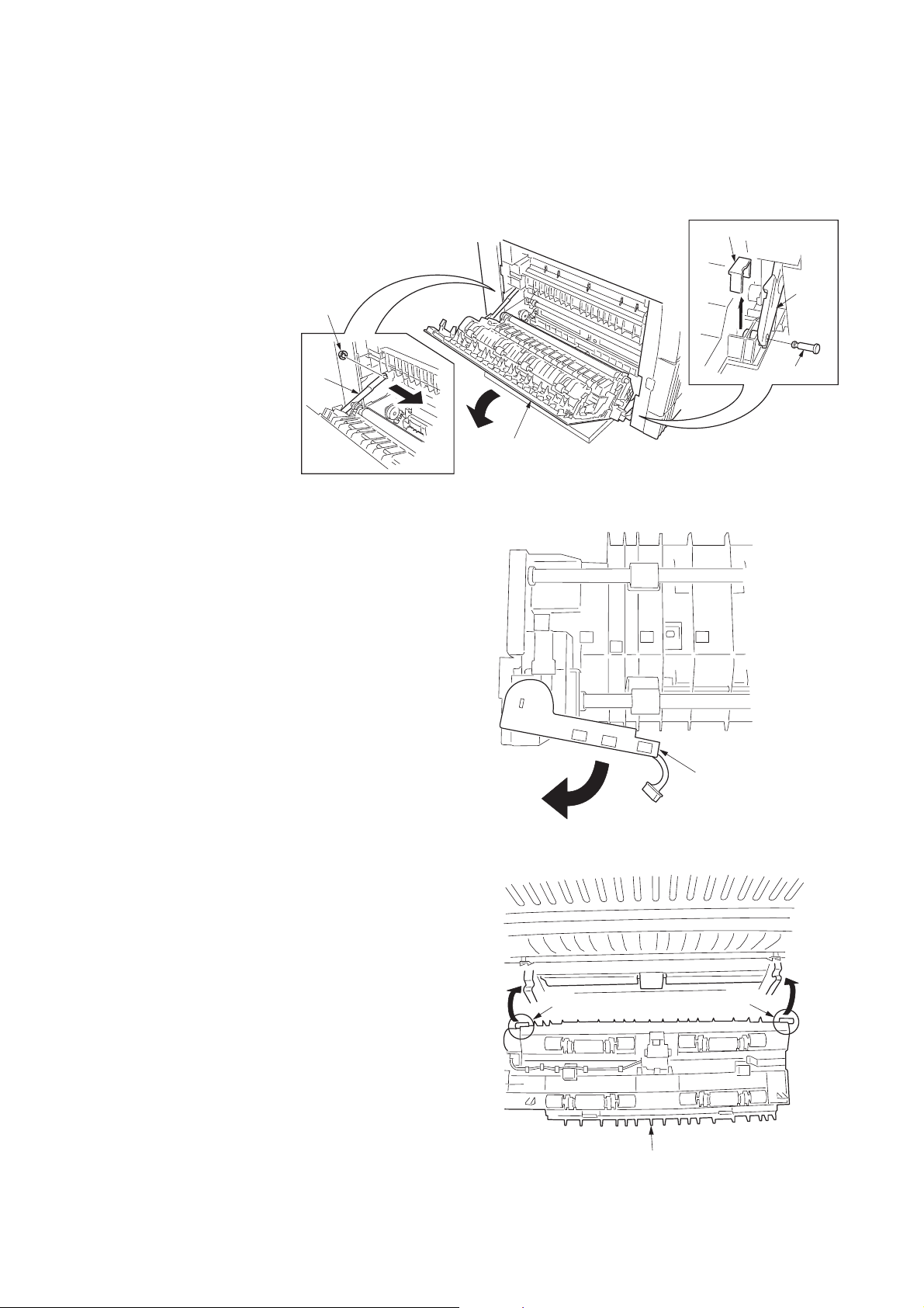
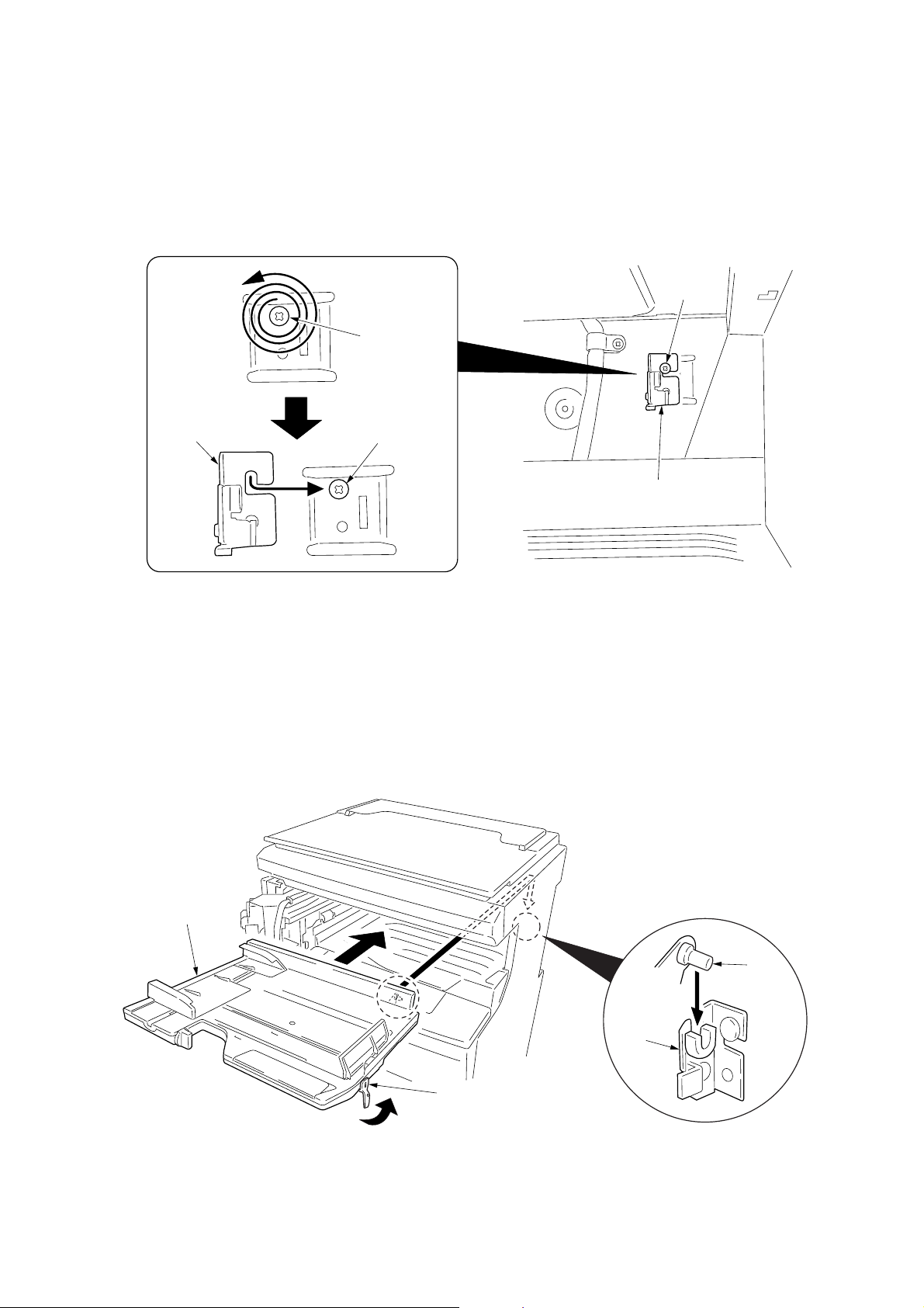
1-3-5 Installing the duplex unit (option)
Left cover
Strap
Stop
ring
Fitting projection
Pin
Stopper
<Procedure>
1. Open the left cover.
2. Remove the stop ring and the strap from the rear
side.
3. Restore the conveyor section.
4. Remove the fitting projection and pin, and then
remove the stopper from the front side.
5. Open the left cover until it is put horizontally.
6. Turn the wire guide section of the duplex unit in the
direction indicated by the arrow.
2FT
Figure 1-3-19
7. Insert the axis sections of the duplex unit into the Ushape grooves of the conveyer unit.
Figure 1-3-20
Axis section
Figure 1-3-21
Wire guide section
Axis section
Duplex unit
1-3-13
Page 35

2FT
8. Press the duplex unit in the direction indicated by the
arrow to fit the claws into the conveyer unit.
9. Hang the hook of the plate lock on the conveying unit
and then turn the plate lock to fit the hole to the claw
of the duplex unit.
Duplex unit
Claws
Claw
Figure 1-3-22-1
10. Secure the duplex unit with the two S tite screws M3
× 06.
Plate lock
Claw
Figure 1-3-22-2
Hook
Hole
Duplex unit
1-3-14
S tite screws
M3 × 06
Figure 1-3-23
Page 36
11. Open the conveyer unit and connect the connector of
the duplex unit to the MFP.
12. Reattach the removed parts to their original
positions.
13. Connect the MFP power plug to the wall outlet and
turn the power switch on.
Adjusting the leading edge timing
1. Run maintenance mode 034.
Select ADJ, RCL ON TIMING and press the start
key.
Select RCL DUP.
Press the Interrupt key to output the test pattern in
the duplex mode and check the image.
If an adequate image cannot be obtained, carry out
the following adjustment.
2. If a test pattern a is obtained, increase the
adjustment value.
If a test pattern b is obtained, decrease the
adjustment value.
Setting range: -5.0 - +10.0
Changing the value by one moves the leading edge
by 0.1 mm.
3. Output the test pattern again.
4. Repeat steps 2 and 3 until an adequate image is
obtained.
2FT
Duplex unit
Connector
Figure 1-3-24
Adequate image Test pattern a Test pattern b
Figure 1-3-25
Adjusting the center line
1. Run maintenance mode 034.
Select ADJ, LSU OUT TIMING and press the start
key.
Select LSU DUP.
Press the Interrupt key to output the test pattern in
the duplex mode and check the image.
If an adequate image cannot be obtained, carry out
the following adjustment.
2. a: Adequate image
2. If a test pattern a is obtained, increase the
adjustment value.
If a test pattern b is obtained, decrease the
adjustment value.
Setting range: -7.0 - +10.0
Changing the value by one moves the center line by
0.1 mm.
3. Output the test pattern again.
4. Repeat steps 2 and 3 until an adequate image is
obtained.
Adequate image Test pattern a Test pattern b
Figure 1-3-26
1-3-15
Page 37
2FT
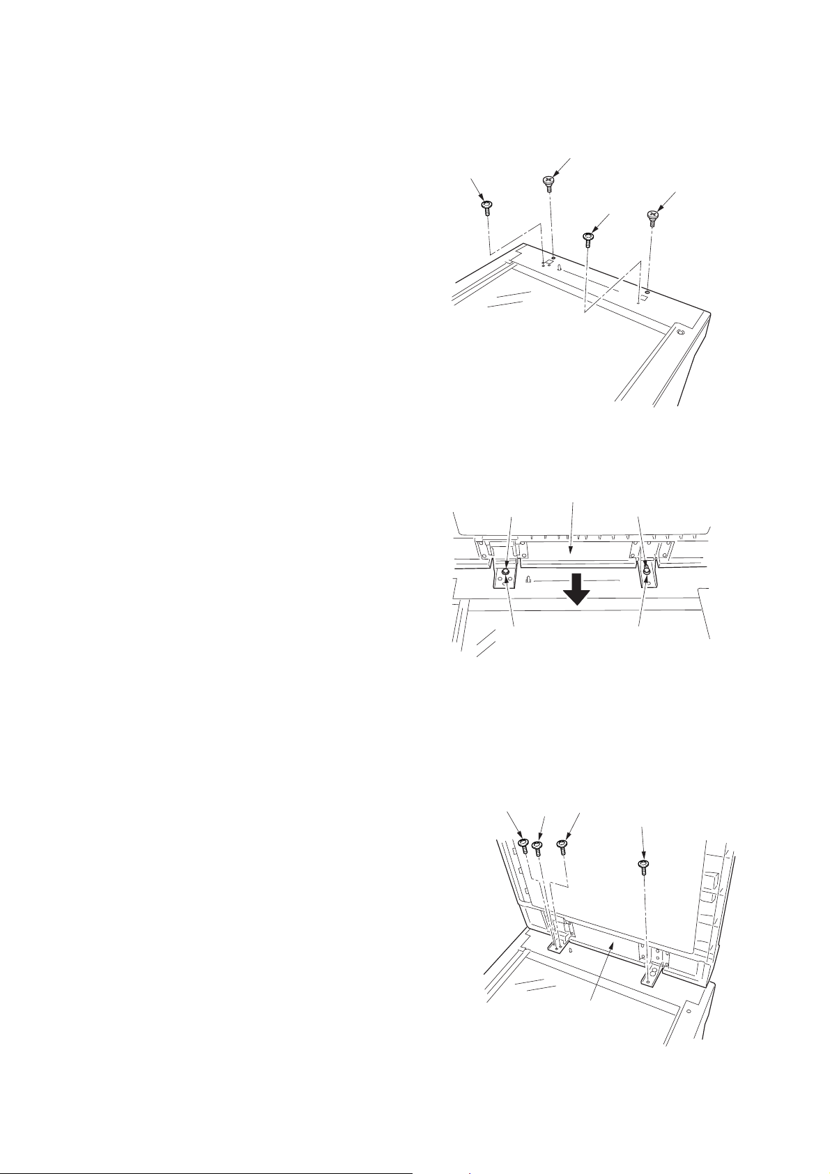
1-3-6 Installing the drawer heater (option)
Drawer heater installation requires the following parts:
• Drawer heater (P/N 120 V specifications: 2C960030, 220-240 V specifications: 2C960040)
• One (1) M4 × 10 tap-tight S binding screw (P/N B3024100)
<Procedure>
1. Remove the main body from the paper feeder (see
page 1-6-7).
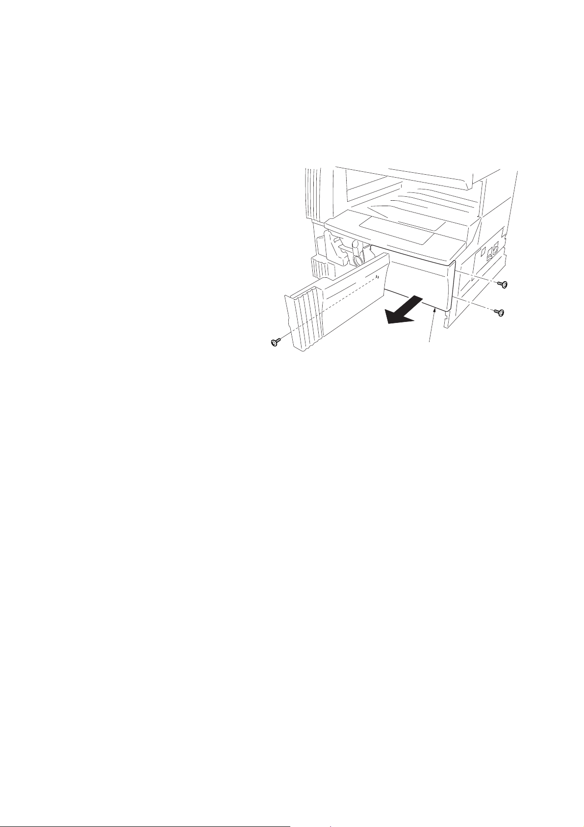
2. Remove the right cover. Pull out the drawer.
3. Remove the three screws and then the front right
cover.
Front right cover
Figure 1-3-27
1-3-16
Page 38

4. Insert the cassette heater from the bottom of the
Drawer heater
Screw hole
Projections
Hole in the right frame
Connector
M4 × 10 tap tight
S binding screw
Holes in the rear frame
machine and attach it to the MFP.
1) Pass the connector of the cassette heater through
the hole located in the right frame of the machine to
pull it out.
2) Insert the projections at the rear side of the cassette
heater mounting plate into the two holes in the rear
frame of the machine.
3) Position the screw hole of the drawer heater to the
screw hole of the front frame of the machine and
secure the heater using the M4 × 10 Taptite S
binding screw.
2FT
Figure 1-3-28
1-3-17
Page 39

2FT
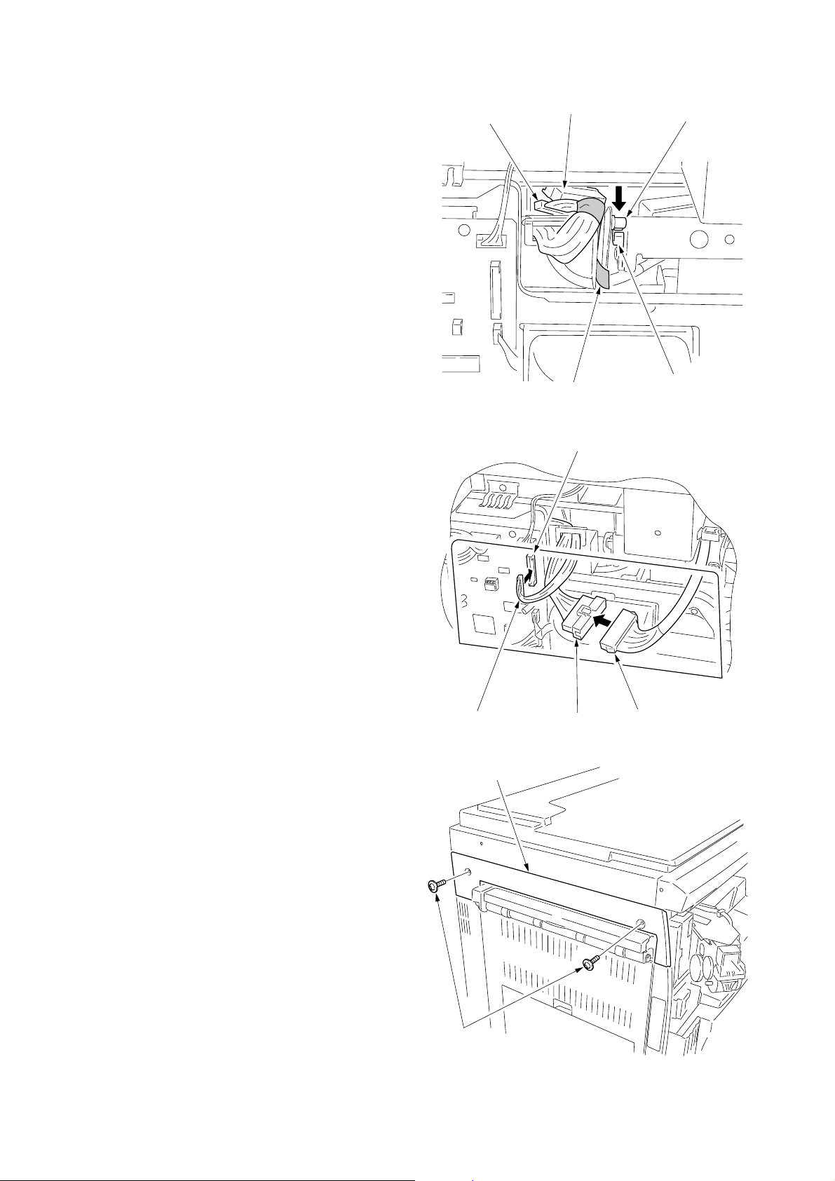
5. Remove the two screws and open the power source
PCB in the direction indicated by the arrow.
* Take care not to open the power source PCB too
much.
6. Fit the wire of the drawer heater into the groove of
the frame and put it inside the power source PCB.
* Fit the wire into the groove so that the band mounted
to the wire is located above the frame.
Wire of the drawer heater
Power source PCB
Band
7. Reattach the power source PCB to its original
position and connect the connector of the drawer
heater to YC8 of the power source PCB.
8. Refit all the removed parts.
Figure 1-3-29
Connector
YC8
Figure 1-3-30
1-3-18
Page 40

1-3-7 Installing the key counter (option)
Key counter installation requires the following parts:
• Key counter cover (P/N 2A360010)
• Key counter retainer (P/N 66060030)
• Key counter mount (P/N 66060040)
• Key counter assembly (P/N 41529210)
• Four (4) M4 × 6 bronze TP-A screws (P/N B4304060)
• One (1) M4 × 35 round head screw (P/N B0004350)
•Two (2) M3 × 6 bronze flat-head screws (P/N B2303060)
• One (1) M3 bronze nut (P/N C2303000)
• Key counter mounting plate (P/N 2C960100)
• Key counter wire (P/N 2C960110)
Procedure
1. Fit the key counter socket assembly to the key
counter retainer using the two screws and nut.
2. Fit the key counter mount to the key counter cover
using the two screws, and attach the key counter
retainer to the mount using the two screws.
2FT
M4 × 6 screws (B4304060)
Key counter retainer (66060030)
M3 nut
(C2303000)
M4 × 6 screws (B4304060)
Key counter socket assembly
(41529210)
M3 × 6 flat-head screws (B2303060)
Figure 1-3-31
Key counter mount (66060040)
Key counter cover
(2A360010)
1-3-19
Page 41
2FT
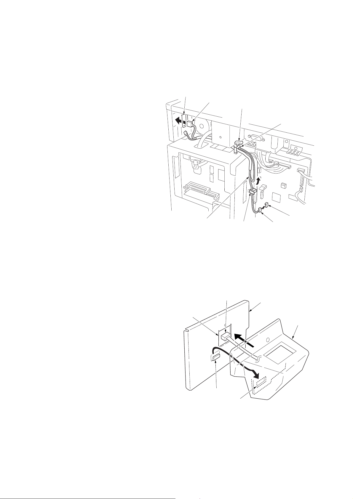
3. Remove the rear cover.
4. Cut out the aperture plate on the right cover using
nippers.
5. Connect the 4-pin connector of the key counter wire
(located at a longer distance from the tube) to YC13
on the engine PCB, pass the wire through the two
clamps, and pull the other 4-pin connector out from
the aperture of the right cover.
* Arrange the key counter wire behind the optical
system wire as shown in the illustration.
6. Fold the 7-pin connector of the key counter wire
back, pass the wire through the clamp at the upper
part of the controller box, and hang it.
Aperture
4-pin connector
7-pin connector
Clamp
7. Pass the connector of the key counter through the
aperture of the key counter mounting plate, and
engage the projection of key counter mounting plate
with the square hole of the key counter cover.
Key counter wire
Aperture
Figure 1-3-32
4-pin connector
Clamp
YC13
4-pin connector
Key counter mounting
plate (2C960100)
Key counter
cover
1-3-20
Projection
Square hole
Figure 1-3-33
Page 42

8. Connect the 4-pin connector of the key counter to the
key counter wire.
9. Engage the projection of the key counter mounting
plate with the aperture of the right cover.
10. Secure the key counter cover and the key counter
mounting plate together with the MFP using a M4 x
35 screw.
11. Refit the rear cover.
Aperture
Key counter wire
4-pin connector
Key counter mounting
plate (2C960100)
2FT
Projection
Key counter
cover
M4×35 screw
(B0004350)
12. Insert the key counter into the key counter socket
assembly.
13. Turn the power switch on and enter the maintenance
mode.
14. Run maintenance item U204 and select “KEYCOUNTER.”
15. Exit the maintenance mode.
16. Check that the message requesting the key counter
to be inserted is displayed on the message display
when the key counter is pulled out.
17. Check that the counter counts up as copies are
made.
Figure 1-3-34
1-3-21
Page 43

2FT
1-3-8 Installing the finisher (option)
<Note>
When placing the transfer unit on the floor or the like, be
sure to place it upside down. If not, the staple mounting
plate may be deformed, resulting in a malfunction.
Transfer unit
Figure 1-3-35
Be sure to remove the tape for the intermediate tray at
Procedure 16 not removing before mounting.
<Procedure>
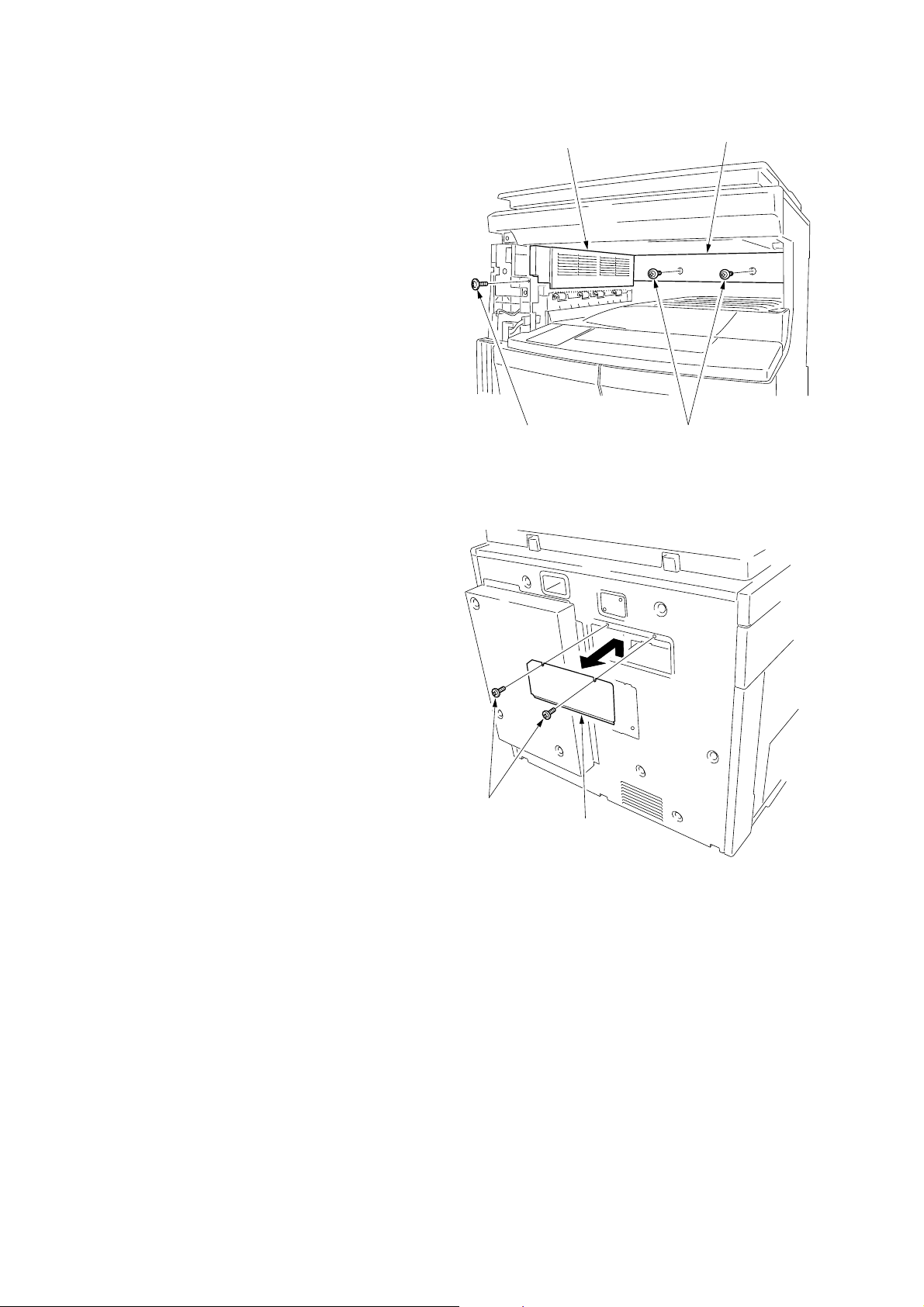
Remove the covers.
1. Remove the two screws to remove the upper left
cover.
Intermediate tray
Figure 1-3-36
Upper left cover
1-3-22
Screws
Figure 1-3-37
Page 44

2. Open the front cover.
3. Remove the inner cover.
4. Release the fitting parts using a small screw driver or
the like and remove the front side cover.
2FT
Inner cover
Figure 1-3-38
5. Remove the screw and the fitting part located on the
right side and then remove the left front cover.
6. Open the front cover.
Fitting parts
Front side cover
Figure 1-3-39
Left front
cover
Screw
Fitting part
Figure 1-3-40
1-3-23
Page 45
2FT
7. Remove the three screws and then remove the
ejection cover and inner ejection cover.
Ejection cover
Inner ejection cover
8. Remove the two screws and then remove the cover.
Screws
Screw
Screws
Figure 1-3-41
Cover
1-3-24
Figure 1-3-42
Page 46

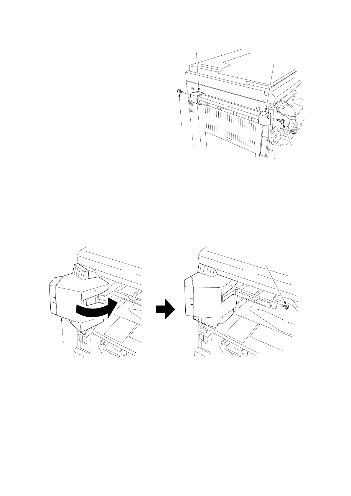
Attach the transfer unit.
9. Insert the transfer unit from the MFP front side and
slide it to the left to install to the ejection part.
10. Place the transfer unit closer to the ejection side and
then secure the front side using the TP bind screw
M3 × 06 and the rear side using the pin.
2FT
Pin
TP bind screw
M3 × 06
Release the lever securing fitting.
11. Loosen the screw located at the rear side of the
transfer unit and release the lever securing fitting in
the direction of an arrow, and then retighten the
screw.
Transfer unit
Figure 1-3-43
Screw
Figure 1-3-44
Lever
securing fitting
1-3-25
Page 47
2FT
Attach the intermediate tray.
12. Loosen the screw located inside of the MFP by about
3 turns.
* Do not turn the screw too much, otherwise it may
drop in the machine.
13. Hang the hook of the hook holder onto the screw and
then retighten the screw.
3
Screw
Hook holder
Screw
Figure 1-3-45
14. Insert the intermediate tray from the front side of the
MFP while pushing the hook to the back and then
push the pin located at the right rear side of the
intermediate tray into the hook holder until the fitting
sound is heard.
Screw
Hook holder
1-3-26
Intermediate
tray
Pin
Hook
holder
Hook
Figure 1-3-46
Page 48
2FT
15. Fit the pin located at the left rear side of the
intermediate tray from the rear side of the MFP onto
the hook of the transfer unit.
16. Remove the tape and pull out the 13-pin connector
and 24-pin connector.
17. Connect the 24-pin connector of the intermediate tray
to the connector of the transfer unit.
18. Connect the 13-pin connector of the intermediate tray
to YC5 on the engine circuit board.
13-pin connector
24-pin connector
Tape
Figure 1-3-47
YC5
Pin
Hook
Attach the covers.
19. Attach the cover that has been removed by
Procedure 8 to its original position using the two
screws.
20. Attach the large ejection cover with the two screws
that have been removed by Procedure 1.
13-pin connector
Large ejection cover
Screws
24-pin connector
Figure 1-3-48
Figure 1-3-49
Connector
1-3-27
Page 49
2FT
21. Attach the front ejection cover and rear ejection
cover using the TP bind screw M3 × 06 each.
22. Open the front cover.
23. Attach the staple cover as it is fitted to the staple unit
from the ejection side and then secure it using the TP
bind screw M3 × 06.
24. Attach the inner cover that has been removed by
Procedure 3 to its original position.
25. Close the front cover.
Rear ejection cover
Front ejection cover
TP bind screw
M3 × 06
TP bind screw
M3 × 06
Figure 1-3-50
Staple cover
TP bind screw M3 × 06
Figure 1-3-51
1-3-28
Page 50

26. Insert the front and rear hooks of the copy tray into
the front ejection cover and rear ejection cover each
and then attach the copy tray.
27. Open the staple cover and then insert the staple
cartridge into the staple unit.
28. Close the staple cover.
2FT
Rear ejection
cover
Copy tray
Front ejection cover
Figure 1-3-52
Operation check
1. Insert the MFP power plug into an outlet and then
turn the power switch on.
2. Select the staple mode and check the staple
operation.
Staple cover
Staple cartridge
Figure 1-3-53
1-3-29
Page 51
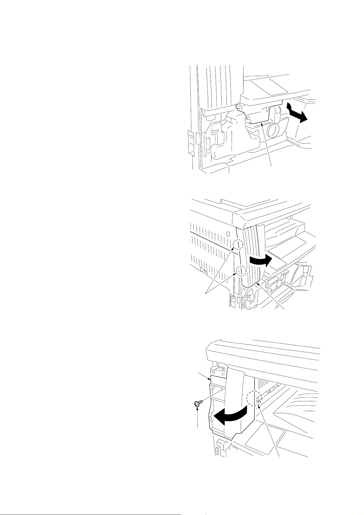
2FT
1-3-9 Installing the job separator (option)
<Procedure>
Remove the covers.
1. Open the front cover.
2. Remove the inner cover.
3. Release the fitting parts using a small screw driver or
the like and remove the front side cover.
Inner cover
Figure 1-3-54
4. Remove the screw and the fitting part located on the
right side and then remove the left front cover.
Fitting parts
Front side cover
Figure 1-3-55
Left front
cover
Screw
Fitting part
Figure 1-3-56
1-3-30
Page 52

5. Remove the three screws and then remove the
ejection cover and inner ejection cover.
Ejection cover
2FT
Inner ejection cover
6. Remove the two screws and then remove the cover.
Screws
Screw
Screws
Figure 1-3-57
Cover
Figure 1-3-58
1-3-31
Page 53

2FT
Attach the job separator.
7. Insert the job separator from the MFP front side and
slide it to the left to install to the ejection part.
8. Place the job separator closer to the ejection side
and then secure the front side (left tapped hole) with
the large pin and the rear side with the small pin.
Small pin
Large pin
Figure 1-3-59
9. Loosen the screw that secures the drive unit located
at the rear side of the job separator to make it ready
for starting to drive and then retighten the screw.
10. Connect the connector of the job separator to YC5
on the engine circuit board.
11. Attach the cover that has been removed by
Procedure 6 to its original position using the two
screws.
YC5
Job separator
Drive unit
1-3-32
Connector
Screw
Figure 1-3-60
Page 54
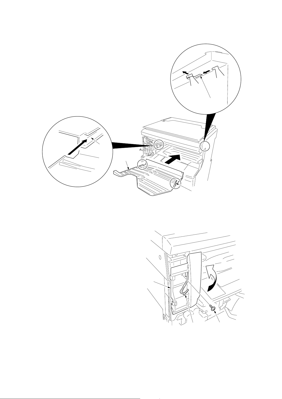
Attach the copy tray.
12. Insert the left part of the copy tray into the groove of
the job separator. Fit the right hook into the hole
located inside of MFP while pushing the copy tray to
the back along the groove.
Groove
Copy tray
2FT
Hole
Attach the left front cover JS.
13. Pull out the connector of the job separator from the
hole of the left front cover that has been removed by
Procedure 4 and then attach the left front cover to its
original position using the screw.
Figure 1-3-61
Left front
cover
Right hook
Connector
Screw
Figure 1-3-62
1-3-33
Page 55

2FT
14. Connect the pulled out connector of the job separator
to the LED PCB of the left front cover JS and then
pass the wire through the two positions of the groove
of the left front cover JS.
15. Fit the pawl of the left front cover JS into the hole of
the left front cover to attach the left front cover JS.
*In this time, take care that the routed wire in the
groove does not come off.
16. Attach the inner cover that has been removed by
Procedure 2 to its original position.
17. Close the front cover.
Connector
LED PCB
Left front cover JS
Grooves
Figure 1-3-63
Operation check
1. Insert the power plug of the MFP into an outlet and
then turn the power switch on.
2. Set the “copy ejection location” of the machine
default settings to job separator.
3. Make a test copy to check that a copy is ejected to
the job separator tray.
Holes
Left front cover JS
Figure 1-3-64
1-3-34
Page 56

1-3-10 Installing the fax system (option)
<Procedure>
Install the optional Memory module DIMM (32MB).
1.Remove the two connectors of the fax control PCB
assembly.
2. Remove the three screws and remove the mounting
plate and the ground wire.
2FT
Screws
Fax control PCB assembly
Ground wire
3. Insert the memory module DIMM at an angle into the
memory slot so that the notch of the memory DIMM
is positioned to the projection of the memory slot on
the fax control PCB assembly. (1)
4. Push the free end of the module down toward the
board. (2)
5. Attach the mounting plate and the ground wire that
have been removed by Procedure 2 with the three
screws to their original positions.
6. Connect the two connectors that have been removed
by Procedure 1.
Projection
Memory slot
Connectors
Figure 1-3-65
Memory slot
Mounting plate
Fax control PCB assembly
Notch
Memory module DIMM
Figure 1-3-66
Memory module DIMM
Memory slot
Memory module DIMM
1-3-35
Page 57
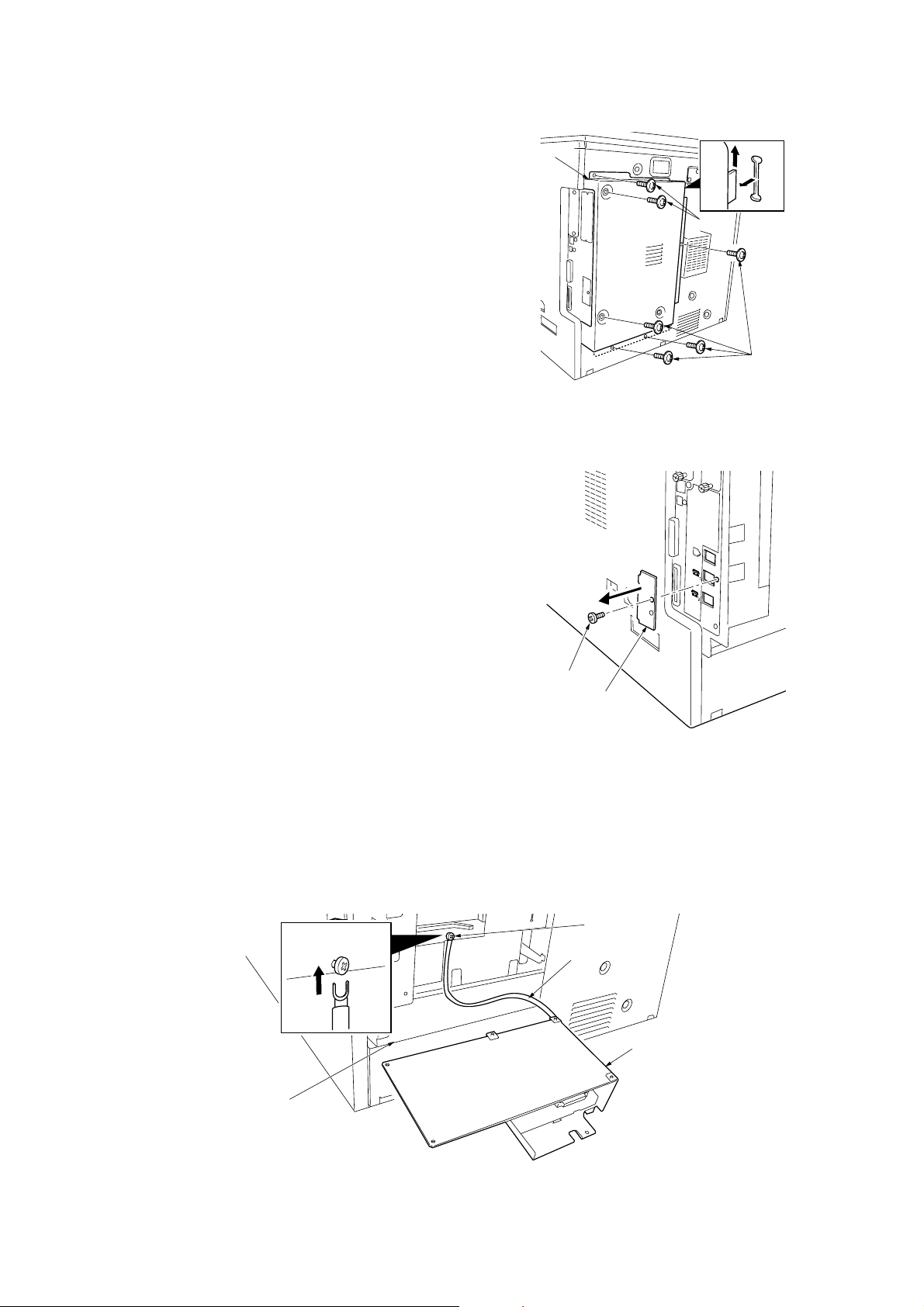
2FT
Remove the shield cover.
7. Remove the six screws, lift the shield cover and then
remove the cover.
Remove the modular cover.
8. Remove the screw and take off the modular cover.
Shield cover
Screws
Screws
Figure 1-3-67
Attach the fax control PCB assembly.
9. Loosen the screw on the printer board.
10. While taking care that the mounting surface of the
board does not contact the frame section of the rear
cover, insert the U terminal of the ground wire of the
fax control PCB assembly and secure it with the
screw.
Frame section
Screw
Modular cover
Figure 1-3-68
Screw
Ground wire
Fax control PCB assembly
1-3-36
Figure 1-3-69
Page 58

11. Connect the YC1 connector on the fax control PCB
assembly to the YC15 connector on the engine PCB.
12. Insert the fax control PCB assembly to the shield box
so that the projection of the fax control PCB
assembly is positioned to the slit of the shield box.
13. Secure the fax control PCB assembly using the three
TP tap tight screws M3 × 6.
Take care that the ground wire is not put on the frame
section of the rear cover.
2FT
Connector
Connector
Shield box
Attach the NCU PCB assembly.
14. Connect the NCU wire connector on the NCU PCB
assembly to the YC2 connector on the fax control
PCB assembly.
YC15
YC1
Fax control
PCB assembly
TP tap tight screws M3 × 6
Figure 1-3-70
Connector
TP tap tight screw M3 × 6
Slit
NCU wire connector
YC2
Projection
NCU PCB assembly
15. Secure the NCU PCB assembly using the four TP
tap tight screws M3 × 6, paying attention so that the
tape section of the shield box does not contact with
the PCB.
Figure 1-3-71
Tape section
TP tap tight screws M3 × 6
NCU PCB assembly
TP tap tight screws M3 × 6
Figure 1-3-72
1-3-37
Page 59

2FT
Attach the modular cover.
16. Attach the modular cover that has been removed by
Procedure 8 with the screw to the position shown in
the illustration.
Install the shield cover.
17. Insert the lower part of the shield cover that has been
removed by Procedure 7 into the shield box and then
attach it with the six screws and TP tap tight screw
M4 × 6 to its original position.
Screw
Modular cover
Figure 1-3-73
Screw
Screw
Screws
Connect the telephone line to the line terminal.
18. Insert the modular connector cable to the line
terminal to connect it to the telephone line.
For 120 V specifications, use supplied modular cord
B.
Shield cover
Lower part
Screw
Shield box
TP tap tight
screw M4 × 6
Figure 1-3-74
Line terminal
Modular connector cable
1-3-38
Figure 1-3-75
Page 60

Attach the operation section sheet for fax.
19. Insert the small screw driver into the two points of the
opening and remove the left cover of the operation
section.
20. Lift the two pawls and remove the operation section
sheet cover.
2FT
Opening
Left cover of
the operation section
Figure 1-3-76
Pawls
21. Remove the operation section sheet and replace it
with the operation section sheet for fax of the
corresponding language.
Operation section sheet cover
Figure 1-3-77
Operation section sheet for fax
Operation section sheet
Figure 1-3-78
1-3-39
Page 61

2FT
22. Fit in the right-side two pawls of the operation section
sheet cover that has been removed by Procedure 20
and then attach the operation section sheet cover to
its original position.
Attach the one-touch securing sheet.
23. Remove the release paper from the one-touch
securing sheet.
24. Adhere the one-touch securing sheet on the base
frame of the one-touch key so that it sticks fast to the
surface while matching the top surface to the top left
corner and firmly pressing the whole area down as
shown in the illustration.
25. Push all the one-touch keys to check that the onetouch securing sheet does not block any one-touch
key.
Operation section sheet cover
Pawl
Pawl
Figure 1-3-79
One-touch securing sheet
Attach the fax label (220-240 V specifications only).
26. Adhere the fax labels (1) to (4) of the fax label
sheet of the corresponding language at the positions
for the cover plate shown in the illustration.
Figure 1-3-80
Fax label sheet
Cover plate
1-3-40
Figure 1-3-81
Page 62

Attach the cover plate.
27. Incurvate the cover plate a little and then insert the
upper and lower projections to the fitting parts of the
operation section to attach.
28. Check that the cover plate smoothly moves on either
side.
Projection
Projection
Figure 1-3-82
2FT
Cover plate
Attach the one-touch sheet.
29. Divide the one-touch sheet of the corresponding
language into two parts and then mount them on the
one-touch securing sheet each.
Bring back the left cover of the operation section that
has been removed by Procedure 19, operation
section sheet that has been removed by Procedure
21, operation section sheet for fax that corresponds
to the unused languages, and the one-touch sheet.
One-touch sheet
Figure 1-3-83
1-3-41
Page 63

2FT
Attach the alphabet labels.
30. Take the alphabet labels from the one-touch label
sheet, and adhere them above the corresponding
numeric keys on the operation panel after wiping the
panel with alcohol.
In Asia and Oceania, use the PQRS TUV WXYZ
label, and do not use the PRS TUV WXZ and OPER
labels.
Attach the certification label (120 V specifications
only).
31. Adhere the FCC68 label onto the shield cover after
wiping the cover with alcohol.
Alphabet labels
Figure 1-3-84
Execute the maintenance mode.
After installation is complete, the fax control PCB must
be initialized by executing the maintenance mode U601/
U602.
(See the service manual of the fax system.)
Shield cover
FCC68 label
10mm
10mm
Figure 1-3-85
1-3-42
Page 64

1-3-11 Installing the scan system (option)
<Procedure>
Remove the covers.
1. Remove the six screws (a), lift the shield cover and
then remove the cover.
If the fax system is installed, remove the six screws
(a) and screw (b), lift the shield cover and then
remove the cover.
2. Remove the two screws, and take off the cover.
2FT
Shield cover
Cover
Screws (a)
Install the scanner board.
3. Insert the scanner board into the OPT1 opening of
the shield box and firmly push the CN5 connector on
the scanner board all the way into the YC12
connector on the engine circuit board.
Screws
Connector
Scanner board
Screw (b)
Screws (a)
Figure 1-3-86
Connector
OPT1 opening
YC12
CN5
4. Fasten the scanner board onto the shield box cover
using the two screws that have been removed by
Procedure 2.
Figure 1-3-87
Scanner board
Screws
Figure 1-3-88
1-3-43
Page 65

2FT
Install the shield cover.
5. Insert the lower part of the shield cover that has been
removed by Procedure 1 into the shield box and refit
it to its original position using the six screws (a).
If the fax system is installed, refit the shield cover
using the six screws (a) and screw (b) to its original
position.
Shield cover
Screw (a)
Screw (a)
Screw (a)
Screw (b)
Lower part
Screws (a)
Shield box
Figure 1-3-89
1-3-44
Page 66
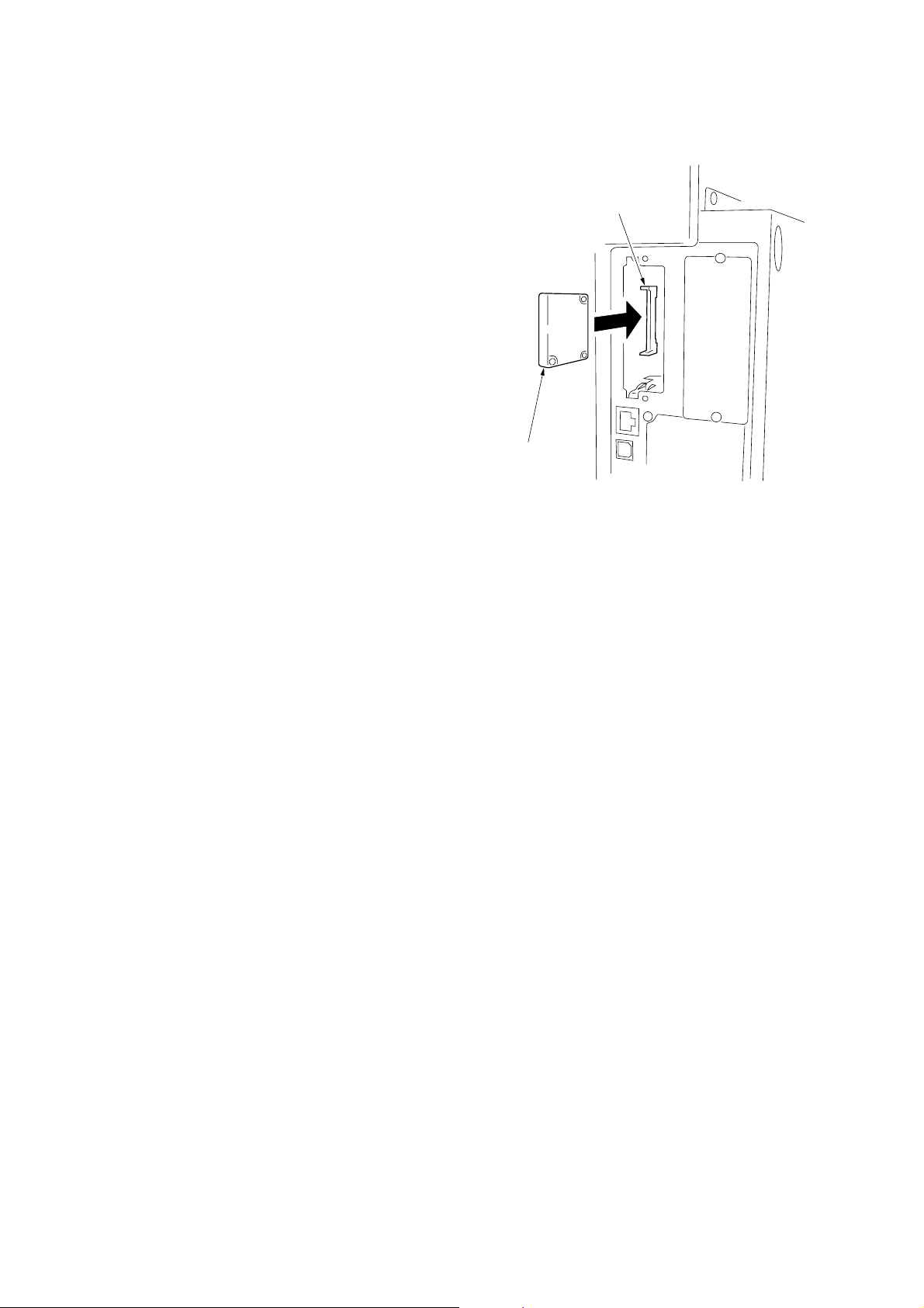
1-3-12 Installing the hard disk (option)
<Procedure>
1. Remove the two screws of the slot for OPT2 which is
on the machine right back, and then remove the
cover.
2. Insert the hard disk in the socket on the printer board
PCB.
3. Refit the cover which is removed with step 1.
4. Turn the power switch on and initialize the hard disk
at the printer menu.
5. Output the printer status report and confirm whether
the hard disk is recognized.
2FT
Socket
Hard disk
Figure 1-3-90
1-3-45
Page 67

1-4-1 Maintenance mode
The machine is equipped with a maintenance function which can be used to maintain and service the machine.
(1) Executing a maintenance item
Start
2FT
Yes
Enter “10871087” using
the numeric keys.
Enter the maintenance item
number using the up/down cursor keys
or numeric keys.
Press the start key.
The selected maintenance item is run.
Press the stop/clear key.
Repeat the same
maintenance item?
Maintenance mode is entered.
The maintenance item is
selected.
Yes
No
Run another maintenance
item?
No
Enter “001” using the up/down
cursor keys or numeric keys
and press the start key.
End
Maintenance mode is exited.
1-4-1
Page 68

2FT-1
(2) Maintenance modes item list
Section
General
Initialization
Drive, paper
feed, paper
conveying and
cooling system
Optical
Item
No. setting*
U000 Outputting an own-status report —
U001 Exiting the maintenance mode —
U002 Setting the factory default data —
U003 Setting the service telephone number
U004 Displaying the machine number —
U005 Copying without paper —
U019 Displaying the ROM version —
U020 Initializing all data —
U021 Initializing memories —
U022 Initializing backup memory —
U026 Evacuation of backup data —
U027 Return of backup data —
U030 Checking motor operation —
U031 Checking switches for paper conveying —
U032 Checking clutch operation —
U034 Adjusting the print start timing
• Adjusting the leading edge registration 4.0/4.0/4.0/
• Adjusting the center line -1.0/0.4/-1.2/
• Adjusting the trailing edge margin -2.0
U035 Setting folio size
• Length/Width 330/210
U051 Adjusting the amount of slack in the paper -10/-15/5/
U053 Performing fine adjustment of the motor speed -0.3/0/-0.6/0.5/
U059 Setting the fan mode 5
U060 Adjusting the scanner input properties 12
U061 Turning the exposure lamp on —
U063 Adjusting the shading position 0
U065 Adjusting the scanner magnification
• Main scanning direction/auxiliary scanning direction 0/-12
U066
Adjusting the leading edge registration for scanning an original on the contact glass
U067 Adjusting the center line for scanning an original on the contact glass -4/0
U068 Adjusting the scanning position for originals from the DP 0
U070 Adjusting the DP magnification 0/0
U071 Adjusting the DP scanning timing 0/0/0/0
U072 Adjusting the DP center line 0/0/0
U073 Checking scanner operation —
U074 Adjusting the DP input light luminosity 0
U076 Executing DP automatic adjustment —
U087 Turning the DP scanning position adjust mode on/off ON/35
U089 Outputting a MIP-PG pattern —
U092 Adjusting the scanner automatically —
U093 Setting the exposure density gradient
•Text and photo/text/photo/text in fax mode/photo in fax mode 0/0/0/2/3
U099 Checking the original size detection —
Maintenance item contents
Initial
***************
4.0/4.0/4.5
-1.2/-1.2/0.3
-20/-20/-5
-0.1/-0.1/-0.2/
-1.3/-1.5/0.6
10/0
* Initial setting for executing maintenance item U020
1-4-2
Page 69

2FT-1
Section
High voltage
Developing
Fixing and
cleaning
Operation
panel and
support
equipment
Mode setting
Item
No. setting*
U100 Checking the operation of main high voltage 60/50/10
U101 Setting high voltages
• Developing bias 25/50/98
• Transfer voltage 155/166/29/28
• Separation voltage 1/27/38/0
U110 Checking/clearing the drum count —
U113 Performing drum refresh operation —
U117 Checking the drum number —
U118 Displaying the drum history —
U130 Initial setting for the developer —
U135 Checking toner motor operation 3
U144 Setting toner loading operation OFF/5/30
U157 Checking/clearing the developing drive time —
U158 Checking the developing count —
U161 Setting the fixing control temperature
• Primary stabilization fixing temperature 152
• Secondary stabilization fixing temperature 170
• Copying operation temperature 1 180
• Copying operation temperature 2 190
• Number of sheets for fixing control 5
• Number of sheets for fixing control (thick paper) 30
U162 Stabilizing fixing forcibly —
U163 Resetting the fixing problem data —
U167 Checking the fixing counts —
U199 Checking the fixing temperature —
U200 Turning all LEDs on —
U202 Setting the KMAS host monitoring system —
U203 Checking DP operation —
U204 Setting the presence or absence of a key card or key counter —
U207 Checking the operation panel keys —
U233 Setting the ejection limit of the job separator MODE0
U243 Checking the operation of the DP motors and solenoids —
U244 Checking the DP switches —
U245 Checking messages —
U246 Setting the finisher 4/4/4
U249 Checking the paper ejection to optional devices —
U250 Setting the maintenance cycle 300000
U251 Checking/clearing the maintenance count —
U252 Setting the destination Japan
U253 Switching between double and single counts Double count
U254 Turning auto start function on/off On
U258 Switching copy operation at toner empty detection Single mode
U260 Changing the copy count timing After ejection
U264 Setting the display order of the date Inch
U265 Setting OEM purchaser code —
U277 Setting auto application change time 30
Maintenance item contents
Initial
specifications:
MONTH-DATE-YEAR
Metric
specifications:
DATE-MONTH-YEAR
* Initial setting for executing maintenance item U020
1-4-3
Page 70

2FT-1
Section
Mode setting
Image
processing
Network
scanner
Others
Item
No. setting*
U326 Setting the black line cleaning indication ON
U332 Setting the size conversion factor 1.0/1.0/1.0
U341 Specific paper feed location setting for printing function —
U342 Setting the ejection restriction On
U343 Switching between duplex/simplex copy mode Off
U344 Setting preheat/energy saver mode Inch
U345 Setting the value for maintenance due indication —
U402 Adjusting margins of image printing 3.0/3.0/4.0
U403 Adjusting margins for scanning an original on the contact glass 2.0/3.0/2.0/2.0
U404 Adjusting margins for scanning an original from the DP 2.0/3.0/2.0/2.0
U407 Adjusting the leading edge registration for memory image printing 0.0
U504 Initializing the scanner NIC —
U506 Setting the time out 10
U901 Checking/clearing copy counts by paper feed locations —
U903 Checking/clearing the paper jam counts —
U904 Checking/clearing the service call counts —
U905 Checking counts by optional devices —
U906 Resetting partial operation control —
U908 Changing the total counter value —
U910 Clearing the black ratio data —
U911 Checking/clearing copy counts by paper sizes —
U917 Setting backup data reading/writing —
U920 Checking the accounting counts —
U925 Checking/clearing the system error counts —
U926 Rewriting FAX program —
U927 Clearing the all accounting counts and machine life counts —
U928 Checking machine life counts —
U941 Setting the default magnification ratio of the default drawer 100 %
U942 Adjusting the DP amount of slack in the original 0
U984 Checking the developing unit number —
U985 Displaying the developing unit history —
U990 Checking/clearing the time for the exposure lamp to light —
U991 Checking the scanner count —
U993 Outputting a VTC-PG pattern —
Maintenance item contents
Initial
specifications:
ENERGY STAR
Metric
specifications:
GEEA
* Initial setting for executing maintenance item U020
1-4-4
Page 71

(3) Contents of maintenance mode items
2FT
Maintenance
item No.
U000 Outputting an own-status report
Description
Outputs lists of the current settings of the maintenance items, and paper jam and service call occurrences.
Purpose
To check the current setting of the maintenance items, or paper jam or service call occurrences.
Before initializing or replacing the backup RAM, output a list of the current settings of the maintenance items to
reenter the settings after initialization or replacement.
Method
1. Press the start key. The screen for selecting an item is displayed.
2. Select the item to be output using the up/down cursor keys. The selected item is displayed in reverse.
Display Output list
MAINTENANCE List of the current settings of the maintenance modes
JAM List of the paper jam occurrences
SERVICE CALL List of the service call occurrences
3. Press the start key. The interrupt print mode is entered and a list is output.
When A4/11" × 81/2" paper is available, a report of this size is output. If not, specify the paper feed location.
When output is complete, the screen for selecting an item is displayed.
Completion
Press the stop/clear key at the screen for selecting an item. The screen for selecting a maintenance item No. is
displayed.
U001 Exiting the maintenance mode
Description
Exits the maintenance mode and returns to the normal copy mode.
Purpose
To exit the maintenance mode.
Method
Press the start key. The normal copy mode is entered.
U002 Setting the factory default data
Description
Restores the machine conditions to the factory default settings.
Purpose
To move the mirror frame of the scanner to the position for transport (position in which the frame can be fixed).
Method
1. Press the start key. The screen for executing is displayed.
2. Select the EXECUTE using the up/down cursor keys. It is displayed in reverse.
3. Press the start key.
The mirror frame of the scanner returns to the position for transport.
Completion
The power switch turns off.
Description
1-4-5
Page 72
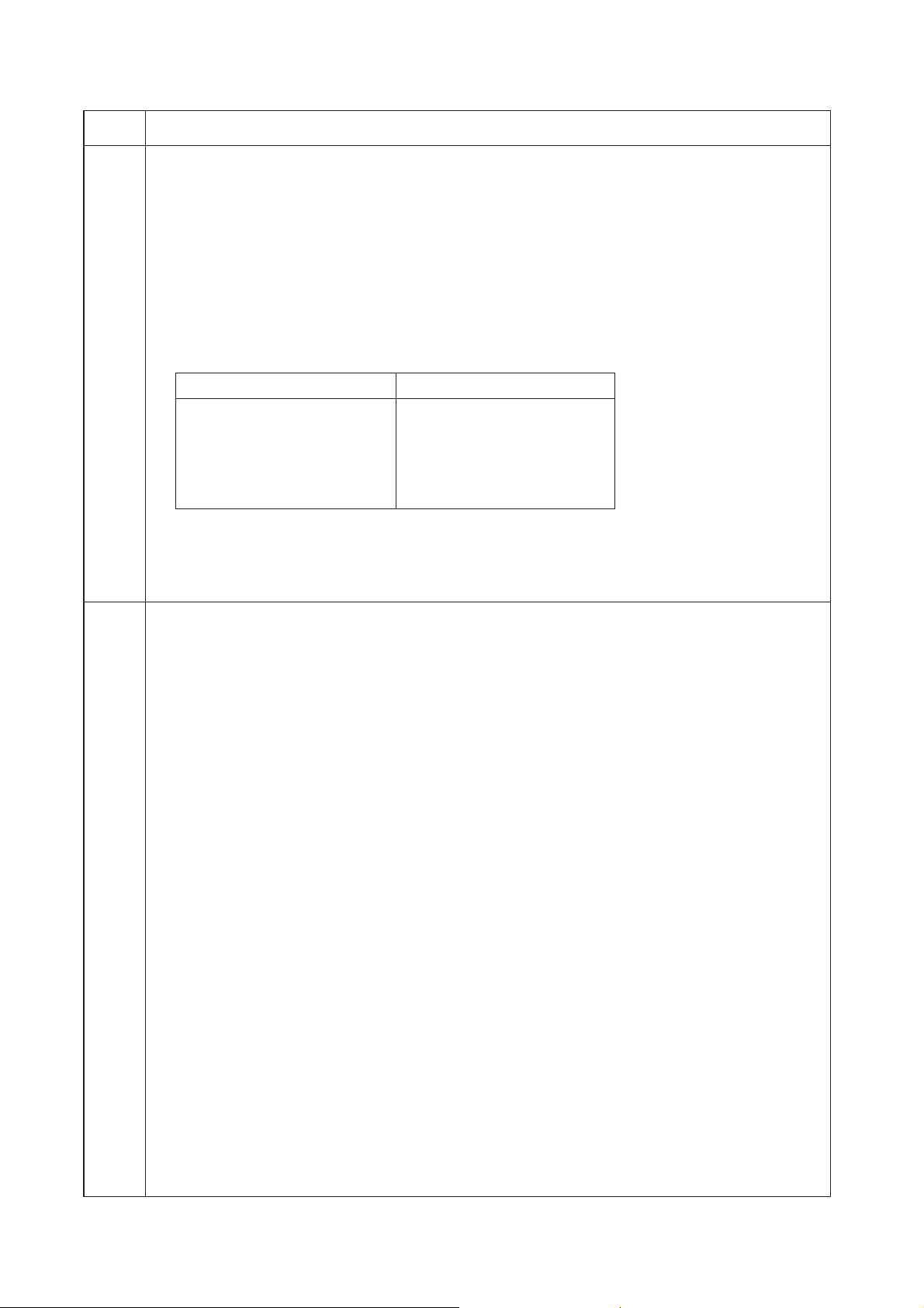
2FT
Maintenance
item No.
U003 Setting the service telephone number
Description
Sets the telephone number to be displayed when a service call code is detected.
Purpose
To set the telephone number to call service when installing the machine.
Method
Press the start key. The currently set telephone number is displayed.
Setting
1. Enter a telephone number (up to 15 digits) using the numeric keys.
Move the cursor using the left/right cursor keys and select a number or symbol using the up/down cursor
keys.
To enter symbols, press the keys shown below as required.
Key Symbol
∗ key ∗
# key #
Image mode selection key (
Aoto mode selection key )
Lighter key –
Darker key Space
2. Press the start key. The phone number is set, and the screen for selecting a maintenance item No. is
displayed.
Completion
To exit this maintenance item without changing the current setting, press the stop/clear key. The screen for
selecting a maintenance item No. is displayed.
U004 Displaying the machine number
Description
Displays the machine number.
Purpose
To check the machine number.
Method
Press the start key. The currently machine number is displayed.
Completion
Press the stop/clear key. The screen for selecting a maintenance item No. is displayed.
Description
1-4-6
Page 73

2FT
Maintenance
item No.
U005 Copying without paper
Description
Simulates the copy operation without paper feed.
Purpose
To check the overall operation of the machine.
Method
1. Press the start key. The screen for selecting an item is displayed.
2. Select the item to be operated using the up/down cursor keys. The selected item is displayed in reverse.
Display Operation
PPC Only the MFP operates.
PPC + DP Both the MFP and DP operate (continuous operation).
3. Press the interrupt key. The copy mode screen is displayed.
4. Set the operation conditions required on the copy mode screen. Changes in the following settings can be
made.
• Paper feed locations
•Magnifications
•Simplex or duplex copy mode
• Number of copies: in simplex copy mode, continuous copying is performed when set to 999; in duplex
copy mode, continuous copying is performed regardless of the setting.
• Copy density
• Keys on the operation panel other than the energy saver (preheat) key
5. To control the paper feed pulley, remove all the paper in the drawers, or the drawers. With the paper
present, the paper feed pulley does not operate.
6. Press the start key. The operation starts.
Copy operation is simulated without paper under the set conditions. When operation is complete, the
screen for selecting an item is displayed.
7. To stop continuous operation, press the stop/clear key.
Completion
Press the stop/clear key at the screen for selecting an item. The screen for selecting a maintenance item No. is
displayed.
Description
1-4-7
Page 74

2FT
Maintenance
item No.
U019 Displaying the ROM version
Description
Displays the part number of the ROM fitted to each PCB.
Purpose
To check the part number or to decide if the ROM version is new from the last digit of the number.
Method
1. Press the start key. The part number indicating the ROM version are displayed.
2. Change the screen using the up/down cursor keys.
Display Description
MAIN Main ROM IC
ENGINE Engine ROM IC
LANG(St) Standard language ROM IC
LANG(Op) Optional language ROM IC
MAIN BOOT Boot of main ROM IC
PRINTER Printer board ROM IC
NWS Network scanner* ROM IC
DP DP* ROM IC
FINISHER Finisher* ROM IC
CASS2 First paper feeder ROM IC
CASS3 Second paper feeder* ROM IC
CASS4 Third paper feeder* ROM IC
*: Optional.
Completion
Press the stop/clear key. The screen for selecting a maintenance item No. is displayed.
U020 Initializing all data
Description
Initializes all the backup RAM on the main PCB to return to the original settings.
Purpose
Run as needed.
Method
1. Press the start key. The screen for executing is displayed.
2. Select the EXECUTE using the up/down cursor keys. It is displayed in reverse.
3. Press the start key. All data in the backup RAM is initialized, and the original settings for Japan
specifications are set.
When initialization is complete, the machine automatically returns to the same status as when the main
switch is turned on.
Completion
To exit this maintenance item without executing initialization, press the stop/clear key. The screen for selecting
a maintenance item No. is displayed.
U021 Initializing memories
Description
Initializes the setting data other than that for adjustments due to variations between respective machines, i.e.,
settings for counters, service call history and mode settings. As a result, initializes the backup RAM according
to the specifications depending on the destination selected in U252.
Purpose
Used to return the machine settings to the factory settings.
Method
1. Press the start key. The screen for executing is displayed.
2. Select the EXECUTE using the up/down cursor keys. It is displayed in reverse.
3. Press the start key. All data other than that for adjustments due to variations between machines is
initialized based on the destination setting.
Completion
To exit this maintenance item without executing initialization, press the stop/clear key. The screen for selecting
a maintenance item No. is displayed.
Description
1-4-8
Page 75

2FT
Maintenance
item No.
U022 Initializing backup memory
Description
Initializes only the data set for the optical section or initializes various setting data when installing the optional
network scanner board.
Purpose
To be executed after replacing the scanner unit or installing the network scanner board.
Method
1. Press the start key. The screen for executing is displayed.
2. Select the EXECUTE using the up/down cursor keys. It is displayed in reverse.
3. Press the start key. The data for the optical section (U060 to 067, U092 to 099, U403, U990 and U991) is
initialized.
The setting data of scanner function initial settings are initialized, and the registered transmission and
reception are cleared.
Completion
Press the stop/clear key. The screen for selecting a maintenance item No. is displayed.
U026 Evacuation of backup data
Description
Transfers the backup data of the main PCB to the EEPROM.
Purpose
Used when replacing the main PCB.
Method
1. Press the start key. The screen for executing is displayed.
2. Select the EXECUTE using the up/down cursor keys. It is displayed in reverse.
3. Press the start key to transfer the backup data.
The screen displays the result.
Description
EXECUTE
CHECK SUM: ∗∗∗∗
CODE : XXXX (See the table below)
Code Description
0000 Processing ends correctly.
0101 Verification abnormality occurs.
0102 Verification abnormality occurs at the time of check sum entry.
4. Press the stop/clear key. The screen for selecting a maintenance item No. is displayed.
Completion
Press the stop/clear key. The screen for selecting a maintenance item No. is displayed.
1-4-9
Page 76
2FT
Maintenance
item No.
U027 Return of backup data
Description
Transfers the backup data of the EEPROM which was transferred with the U026 to flash memory.
Purpose
To use after the main PCB replaced.
Method
1. Press the start key. The screen for executing is displayed.
2. Select the EXECUTE using the up/down cursor keys. It is displayed in reverse.
3. Press the start key to transfer the backup data.
The screen displays the result.
EXECUTE
CHECK SUM: ∗∗∗∗
CODE : XXXX (See the table below)
Code Description
0000 Processing ends correctly.
0203 Check sum does not agree when reading out from the EEPROM.
4. Disconnect and connect the power plug.
Completion
Press the stop/clear key. The screen for selecting a maintenance item No. is displayed.
U030 Checking motor operation
Description
Drives each motor.
Purpose
To check the operation of each motor.
Method
1. Press the start key. The screen for selecting an item is displayed.
2. Select the motor to be operated using the up/down cursor keys.
3. Press the start key. The operation starts.
Display Operation
MAIN Drive motor (DM) operates
RES Registration motor (RM) operates
T1 Drawer drive motor 1 (DDM1) operates
T2 Drawer drive motor 2* (DDM2) operates
T3 Drawer drive motor 3* (DDM3) operates
EJE1 Eject motor rotates forward
EJE2 Eject motor rotates in reverse
*: Optional.
4. To stop operation, press the stop/clear key.
Completion
Press the stop key after operation stops. The screen for selecting a maintenance item No. is displayed.
Description
1-4-10
Page 77
2FT
Maintenance
item No.
U031 Checking switches for paper conveying
Description
Displays the on-off status of each paper detection switch on the paper path.
Purpose
To check if the switches for paper conveying operate correctly.
Method
1. Press the start key. A list of the switches, the on-off status of which can be checked, are displayed.
2. Turn each switch on and off manually to check the status.
When the on-status of a switch is detected, that switch is displayed in reverse.
Display Switches
EJE Eject switch (ESW)
RES Registration switch (RSW)
PF2 Drawer feed switch 1 (DFSW1)
PF3 Drawer feed switch 2* (DFSW2)
BRA Feedshift switch (FSSW)
DUP Duplex paper conveying switch* (DUPPCSW)
JOB Job separator eject switch* (JBESW)
*: Optional.
Completion
Press the stop/clear key. The screen for selecting a maintenance item No. is displayed.
U032 Checking clutch operation
Description
Turns each clutch on.
Purpose
To check the operation of each clutch.
Method
1. Press the start key. The screen for selecting an item is displayed.
2. Select the clutch to be operated using the up/down cursor keys.
3. Press the start key. The clutch turns on for 1 s.
Display Clutches
PF1 Paper feed clutch (PFCL)
PFBYP Bypass paper feed solenoid (BYPPFSOL)
FEED1 Drawer paper feed clutch 1 (DPFCL1)
FEED2 Drawer paper feed clutch 2* (DPFCL2)
FEED3 Drawer paper feed clutch 3* (DPFCL3)
*: Optional.
Completion
Press the stop/clear key. The screen for selecting a maintenance item No. is displayed.
Description
1-4-11
Page 78

2FT-1
Maintenance
item No.
U034 Adjusting the print start timing
Adjustment
See pages 1-6-16 and 18.
U035 Setting folio size
Description
Changes the image area for copying onto folio size paper.
Purpose
To prevent the image at the trailing edge, or right or left side of the paper from not being copied by setting the
actual size of the folio paper used.
Method
Press the start key. The screen for setting is displayed.
Setting
1. Select the item to be set using the up/down cursor keys. The selected item is displayed in reverse.
2. Change the setting using the left/right cursor keys.
Display Setting Setting range Initial setting
LENGTH DATA Length 330 to 356 mm 330
WIDTH DATA Width 200 to 220 mm 210
3. Press the start key. The value is set.
Completion
Press the stop/clear key. The screen for selecting a maintenance item No. is displayed.
U051 Adjusting the amount of slack in the paper
Adjustment
See page 1-6-21.
U053 Performing fine adjustment of the motor speed
Description
Performs fine adjustment of the speeds of the motors.
Purpose
Used to adjust the speed of the respective motors when the magnification is not correct. Also speed adjustment
for each paper source.
Method
Press the start key. The screen for setting is displayed.
Setting
1. Select the item to be set using the up/down cursor keys. The selected item is displayed in reverse.
2. Change the setting using the left/right cursor keys.
Display Description Setting range Initial setting
MAIN Drive motor speed adjustment –5.0 to +5.0 –0.3
POLY Polygon motor speed adjustment –5.0 to +4.0 0
EJE Eject motor speed adjustment –5.0 to +5.0 –0.6
RES Registration motor speed adjustment –5.0 to +5.0 0.5
BYP Motor speed adjustment –5.0 to +5.0 –0.1
(for paper feed from bypass tray)
CAS Motor speed adjustment –5.0 to +5.0 –0.1
(for paper feed from paper feeder)
DUP Motor speed adjustment –5.0 to +5.0 –0.2
(in duplex mode)
EJE2 Eject motor speed (optional ejection correction value –5.0 to +5.0 –1.3
in the case of paper size of A3, B4, and 11" × 17")
EJE3 Eject motor speed (optional ejection correction value –5.0 to +5.0 –1.5
in the case of paper size other than those above)
EJE4 Eject motor speed (ejection motor correction value 0 to +5.0 0.6
at the time of duplex inner ejection)
Description
1-4-12
Page 79
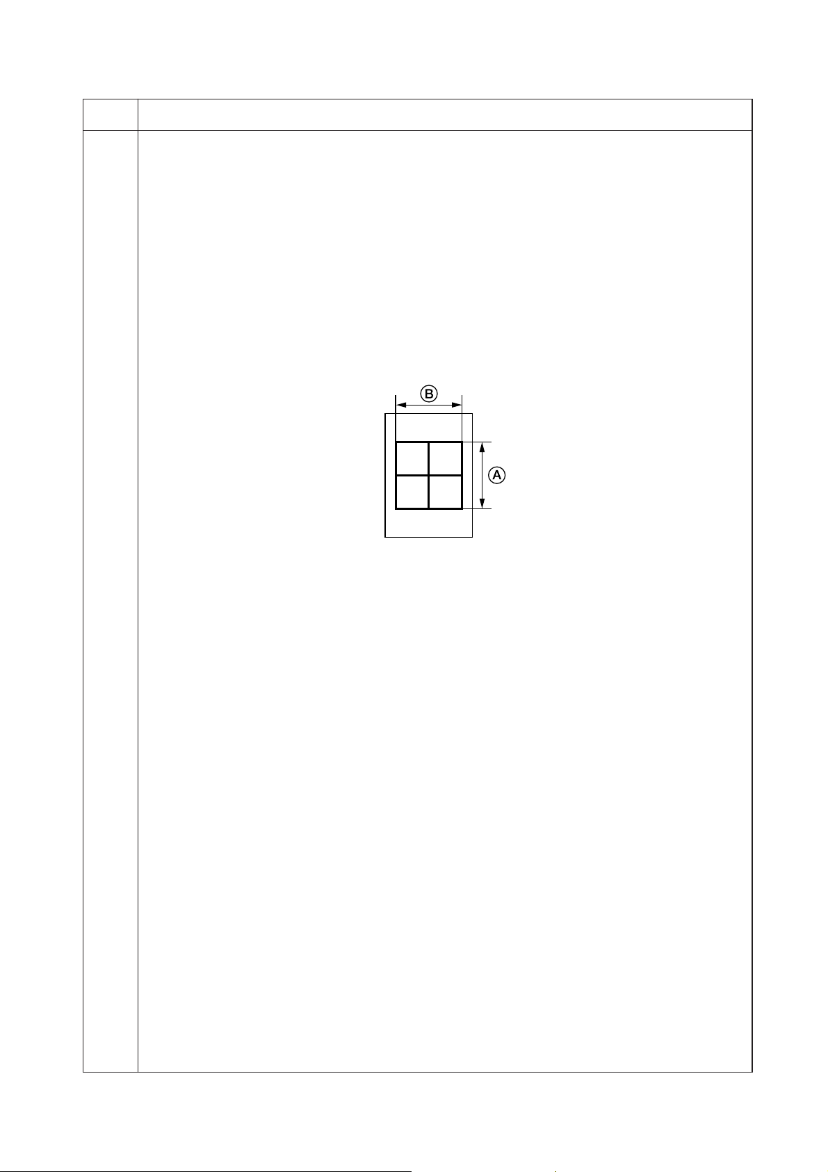
2FT
Maintenance
item No.
U053 MAIN MOTOR
Increasing the setting makes the image longer in the auxiliary scanning direction, and decreasing it makes
the image shorter in the auxiliary scanning direction.
POLYGON MOTOR
Increasing the setting makes the image longer in the main scanning direction and shorter in the auxiliary
scanning direction; decreasing the setting makes the image shorter in the main scanning direction and
longer in the auxiliary scanning direction.
3. Press the start key. The value is set.
Interrupt copy mode
While this maintenance item is being performed, a VTC pattern shown below is output in interrupt copy mode.
1. Press the interrupt key. The machine enters the interrupt copy mode.
2. Press the start key. A VTC pattern is output.
To return to the screen for setting, press the interrupt key.
Correct values for an A3/11" × 17" output are:
A = 300 ± 1.5 mm
B = 270 ± 1.35 mm
Description
Figure 1-4-1
Adjustment
1. Output an A3/11" × 17" VTC pattern in interrupt copy mode.
2. Measure A and B on the VTC pattern (Figure 1-4-1), and perform the following adjustments if they are
different from the correct sizes:
A: Drive motor speed adjustment
B: Polygon motor speed adjustment
Completion
Press the stop/clear key at the screen for setting. The screen for selecting a maintenance item No. is displayed.
1-4-13
Page 80

2FT-1
Maintenance
item No.
U059 Setting the fan mode
Description
Setting the rotation time of a cooling fan motor 2.
Purpose
Change the value when the image flow occurs.
Method
Press the start key. The screen for setting is displayed.
Setting
1. Change the setting using the left/right cursor keys.
Descrition Setting range Initial setting
Rotation time of cooling fan motor 2 0 to +30 (s) 5
2. Press the start key. The value is set.
Completion
Press the stop/clear key. The screen for selecting a maintenance item No. is displayed.
U060 Adjusting the scanner input properties
Description
Adjusts the image scanning density in text, text and photo, or photo mode.
Purpose
Used when the entire image appears too dark or light.
Method
Press the start key. The screen for setting is displayed.
Setting
1. Change the setting using the left/right cursor keys.
Descrition Setting range Initial setting
Image scannnig density 1 to +23 12
Increasing the setting makes the density lower, and decreasing it makes the density higher.
2. Press the start key. The value is set.
Interrupt copy mode
While this maintenance item is being performed, copying from an original can be made in interrupt copy mode.
1. Press the interrupt key. The machine enters the interrupt copy mode.
2. Set the original and press the strat key.
To return to the screen for setting, press the interrupt key.
Completion
Press the stop/clear key at the screen for setting. The screen for selecting a maintenance item No. is displayed.
U061 Turning the exposure lamp on
Description
Turns the exposure lamp on.
Purpose
To check the exposure lamp.
Method
1. Press the start key. The screen for executing is displayed.
2. Press the start key. The exposure lamp lights.
3. To turn the exposure lamp off, press the stop/clear key.
Completion
Press the stop/clear key. The screen for selecting a maintenance item No. is displayed.
Description
1-4-14
Page 81

2FT
Maintenance
item No.
U063 Adjusting the shading position
Description
Changes the shading position.
Purpose
Used when white lines continue to appear longitudinally on the image after the shading plate is cleaned. This is
due to flaws or stains inside the shading plate. To prevent this problem, the shading position should be changed
so that shading is possible without being affected by the flaws or stains.
Method
1. Press the start key. The screen for setting is displayed.
2. Change the setting using the left/right cursor keys.
Description Setting range Initial setting Change in value per step
Shading position –8 to +8 0 0.17 mm
Increasing the setting moves the shading position toward the machine right, and decreasing it moves the
position toward the machine left.
3. Press the start key. The value is set.
Interrupt copy mode
While this maintenance item is being performed, copying from an original can be made in interrupt copy mode.
1. Press the interrupt key. The machine enters the interrupt copy mode.
2. Set the original and press the strat key.
To return to the screen for setting, press the interrupt key.
Completion
Press the stop/clear key at the screen for setting. The screen for selecting a maintenance item No. is displayed.
U065 Adjusting the scanner magnification
Adjustment
See pages 1-6-33 and 34.
U066 Adjusting the leading edge registration for scanning an original on the contact glass
Adjustment
See page 1-6-35.
U067 Adjusting the center line for scanning an original on the contact glass
Adjustment
See page 1-6-36.
U068 Adjusting the scanning position for originals from the DP
Description
Adjusts the position for scanning originals from the DP.
Purpose
Used when there is a regular error between the leading edges of the original and the copy image when the DP
is used.
Method
Press the start key. The screen for setting is displayed.
Setting
1. Change the setting using the left/right cursor keys.
Description Setting range Initial setting Change in value per step
Scanning position –17 to +17 0 0.17 mm
Increasing the setting moves the image backward, and decreasing it moves the image forward.
2. Press the start key. The value is set.
Completion
Press the stop/clear key. The screen for selecting a maintenance item No. is displayed.
Description
1-4-15
Page 82
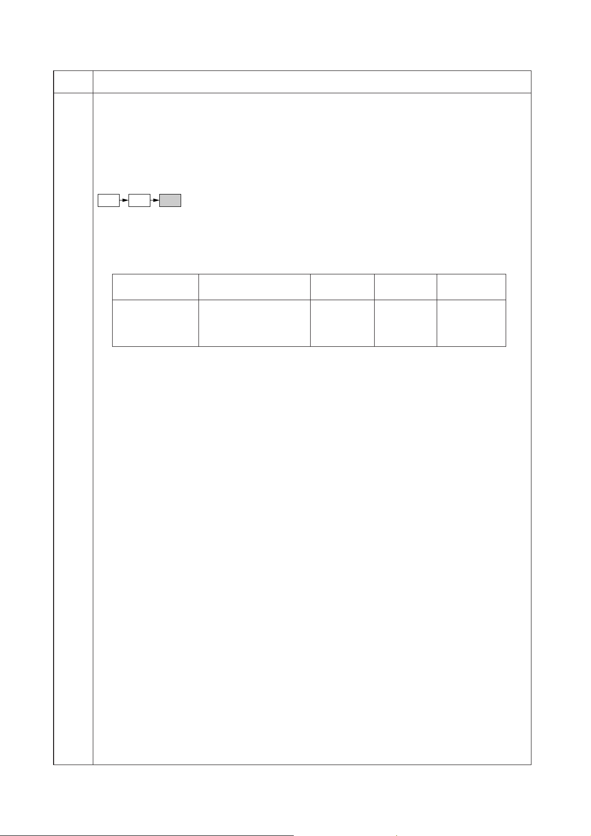
2FT
Maintenance
item No.
U070 Adjusting the DP magnification
Description
Adjusts the DP original scanning speed.
Purpose
To be executed if the correct magnification is not obtained in the auxiliary scanning direction when the optional
DP is used.
Caution
Before making this adjustment, ensure that the following adjustments have been made in maintenance mode.
U053 U065 U070
Method
Press the start key. The screen for setting is displayed.
Setting
1. Select the item to be set using the up/down cursor keys. The selected item is displayed in reverse.
2. Change the setting using the left/right cursor keys.
Display Description Setting range Initial setting
CONVEY SPEED1 Original conveying motor –25 to +25 0 0.1%
speed (simplex original)
CONVEY SPEED2 Original conveying motor –25 to +25 0 0.1%
speed (duplex original)
Increasing the setting makes the image longer, and decreasing it makes the image shorter.
3. Press the start key. The value is set.
Interrupt copy mode
While this maintenance item is being performed, copying from an original can be made in interrupt copy mode.
1. Press the interrupt key. The machine enters the interrupt copy mode.
2. Set the original and press the strat key.
To return to the screen for setting, press the interrupt key.
Completion
Press the stop/clear key at the screen for setting. The screen for selecting a maintenance item No. is displayed.
Description
Change in
value per step
1-4-16
Page 83

2FT
Maintenance
item No.
U071 Adjusting the DP scanning timing
Description
Adjusts the DP original scanning timing.
Purpose
To be executed if there is a regular error between the leading or trailing edges of the original and the copy
image when the optional DP is used.
Caution
Before making this adjustment, ensure that the following adjustments have been made in maintenance mode.
U034 U066 U071
Method
Press the start key. The screen for setting an item is displayed.
Setting
1. Select the item to be set using the up/down cursor keys. The selected item is displayed in reverse.
2. Change the setting using the left/right cursor keys.
Display Description Setting range Initial setting
LEAD1 DP leading edge registration –32 to +22 0 0.2 mm
(simplex original)
TRAIL1 DP trailing edge registration –22 to +32 0 0.2 mm
(simplex original)
LEAD2 DP leading edge registration –32 to +22 0 0.2mm
(duplex original)
TRAIL2 DP trailing edge registration –22 to +32 0 0.2mm
(duplex original)
Increasing the setting moves the copy image backward, and decreasing it moves the copy image forward.
3. Press the start key. The value is set.
Interrupt copy mode
While this maintenance item is being performed, copying from an original can be made in interrupt copy mode.
1. Press the interrupt key. The machine enters the interrupt copy mode.
2. Set the original and press the strat key.
To return to the screen for setting, press the interrupt key.
Adjustment
1. In interrupt copy mode, make a copy using the DP.
2. Check the copy image and adjust the registration as follows.
For copy example 1, decrease the setting of LEAD1 or LEAD2.
For copy example 2, increase the setting of LEAD1 or LEAD2.
Description
Change in
value per step
Original Copy
example 1
Copy
example 2
Figure 1-4-2
Completion
Press the stop/clear key at the screen for setting. The screen for selecting a maintenance item No. is displayed.
1-4-17
Page 84
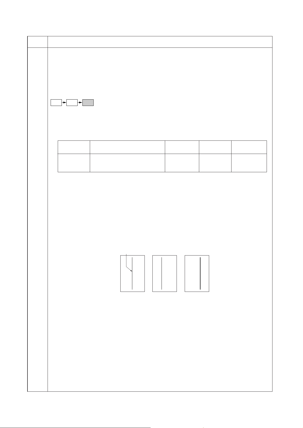
2FT
Maintenance
item No.
U072 Adjusting the DP center line
Description
Adjusts the scanning start position for the DP original.
Purpose
To be executed if there is a regular error between the centers of the original and the copy image when the
optional DP is used.
Caution
Before making this adjustment, ensure that the following adjustments have been made in maintenance mode.
U034 U067 U072
Method
Press the start key. The screen for setting is displayed.
Setting
1. Select the item to be set using the up/down cursor keys. The selected item is displayed in reverse.
2. Change the setting using the left/right cursor keys.
Display Description Setting range Initial setting
1 sided Simplex copy mode –39 to +39 0 0.1 mm
2 sided front Front face in duplex copy mode –39 to +39 0 0.1 mm
2 sided back Reverse face in duplex copy mode –39 to +39 0 0.1 mm
Increasing the setting moves the image to the right, and decreasing it moves the image to the left.
3. Press the start key. The value is set.
Interrupt copy mode
While this maintenance item is being performed, copying from an original can be made in interrupt copy mode.
1. Press the interrupt key. The machine enters the interrupt copy mode.
2. Set the original and press the strat key.
To return to the screen for setting, press the interrupt key.
Adjustment
1. In interrupt copy mode, make a copy using the DP.
2. Check the copy image and adjust the center line as follows.
For copy example 1, increase the setting.
For copy example 2, decrease the setting.
Description
Change in
value per step
Reference
Original Copy
example 1
Copy
example 2
Figure 1-4-3
Completion
Press the stop/clear key at the screen for setting. The screen for selecting a maintenance item No. is displayed.
1-4-18
Page 85
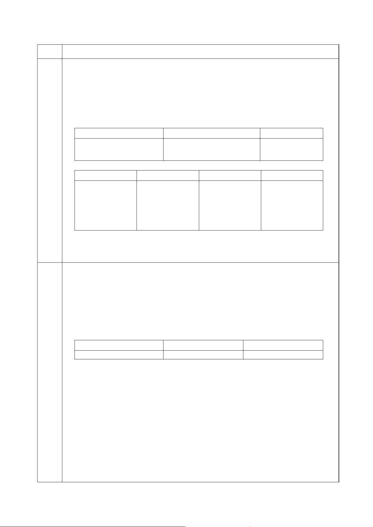
2FT
Maintenance
item No.
U073 Checking scanner operation
Description
Simulates the scanner operation under arbitrary conditions.
Purpose
To check scanner operation.
Method
1. Press the start key. The screen for selecting an item is displayed.
2. Select the item to be changed using the up/down cursor keys. The selected item is displayed in reverse.
3. Change the setting using the left/right cursor keys.
Display Operating conditions Setting range
ZOOM Magnification 100 to 400%
SIZE Original size See below.
LAMP On and off of the exposure lamp 0 (off) or 1 (on)
Original sizes for each setting in SIZE
Setting Paper size Setting Paper size
8A442A5R
9B547Folio
24 11" × 8
36 A3 53 11" × 15"
39 B4 55 81/2" × 14"
40 A4R 56 8
41 B5R 58 51/2" × 81/2"
4. Press the start key. Scanning starts under the selected conditions.
5. To stop operation, press the stop/clear key.
Completion
Press the stop/clear key when scanning stops. The screen for selecting a maintenance item No. is displayed.
U074 Adjusting the DP input light luminosity
Description
Adjusts the luminosity of the exposure lamp for scanning originals from the DP.
Purpose
Used if the exposure amount differs significantly between when scanning an original on the contact glass and
when scanning an original from the DP.
Method
Press the start key.
Setting
1. Change the setting using the left/right cursor keys.
Description Setting range Initial setting
DP input light luminosity 0 to 8 0
Increasing the setting makes the luminosity higher, and decreasing it makes the luminosity lower.
2. Press the start key. The value is set.
Interrupt copy mode
While this maintenance item is being performed, copying from an original can be made in interrupt copy mode.
1. Press the interrupt key. The machine enters the interrupt copy mode.
2. Set the original and press the strat key.
To return to the screen for setting, press the interrupt key.
Completion
Press the stop/clear key. The screen for selecting a maintenance item No. is displayed.
Description
1
/2"52 11" × 17"
1
/2" × 11"
1-4-19
Page 86

2FT-1
Maintenance
item No.
U076 Executing DP automatic adjustment
Description
Uses a specified original and automatically adjusts the following items in the DP scanning section.
• Adjusting the DP magnification (U070)
• Adjusting the DP scanning timing (U071)
• Adjusting the DP center line (U072)
When you run this maintenance mode, the preset values of U070, U071 and U072 will also be updated.
Purpose
To perform automatic adjustment of various items in the DP scanning section.
Method
1. Set a specified original (part number: 2A068021) in the DP.
2. Press the start key. The screen for executing is displayed.
3. Press the start key. Auto adjustment starts. When adjustment is complete, each adjusted value is
displayed.
Display Description
CONVEY SPEED DP magnification in the auxiliary scanning direction
LEAD EDGE ADJ DP leading edge registration
DP CENTER DP original center line
If a problem occurs during auto adjustment, DATA: XX (XX is replaced by an error code) is displayed and
operation stops. Should this happen, determine the details of the problem and either repeat the procedure
from the beginning, or adjust the remaining items manually by running the corresponding maintenance
items.
Completion
Press the stop/clear key after auto adjustment is complete. The screen for selecting a maintenance item is
displayed.
If the stop/clear key is pressed during auto adjustment, adjustment stops and no settings are changed.
Description
1-4-20
Page 87
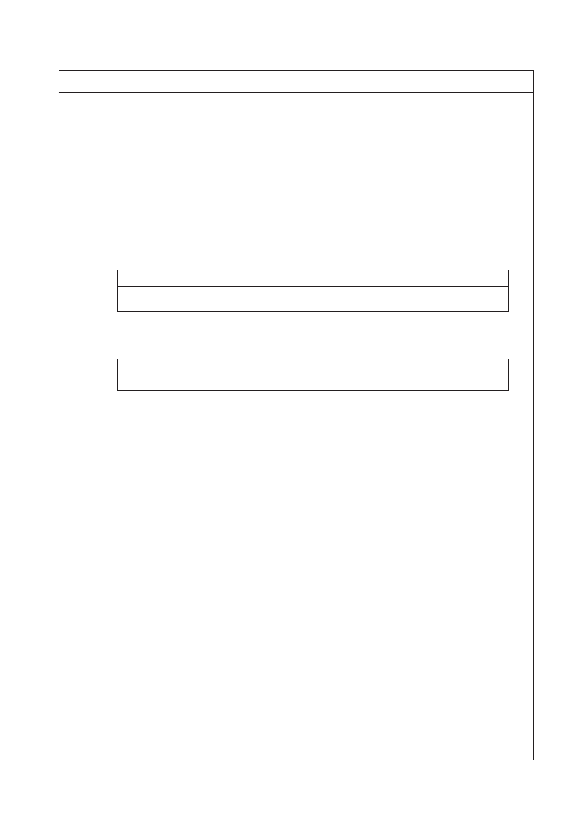
2FT
Maintenance
item No.
U087 Turning the DP scanning position adjust mode on/off
Description
Turns on or off the DP scanning position adjust mode, in which the DP original scanning position is adjusted
automatically by determining the presence or absence of dust on the slit glass. Also changes the reference
data for identifying dust.
Reference
In the DP original scanning position adjust mode, the presence or absence of dust is determined by comparing
the scan data of the original trailing edge and that taken after the original is conveyed past the DP original
scanning position. If dust is identified, the DP original scanning position is adjusted for the following originals.
Purpose
Used to prevent appearance of black lines due to dust adhering in the original scanning position on the slit
glass when the DP is used.
Setting
1. Press the start key. The screen for selecting an item is displayed.
2. Select ON or OFF using the up/down cursor keys. The selected item is displayed in reverse.
Display Description
ON DP scanning position adjust mode on
OFF DP scanning position adjust mode off
Initial setting: ON
Available only when the mode is turned on.
3. Change the setting using the left/right cursor keys.
Description Setting range Initial setting
Minimum density to be regarded as dust 10 to 95 35
Description
Example
The figure indicates the density in 256 levels of gray (0: white, 255: black). When the setting is 35, data of
the level of 35 or higher is regarded as dust and data of lower level is regarded as the background (scan
data taken when there is no original).
4. Press the start key. The value is set.
Completion
Press the stop/clear key. The indication for selecting a maintenance item No. appears.
1-4-21
Page 88
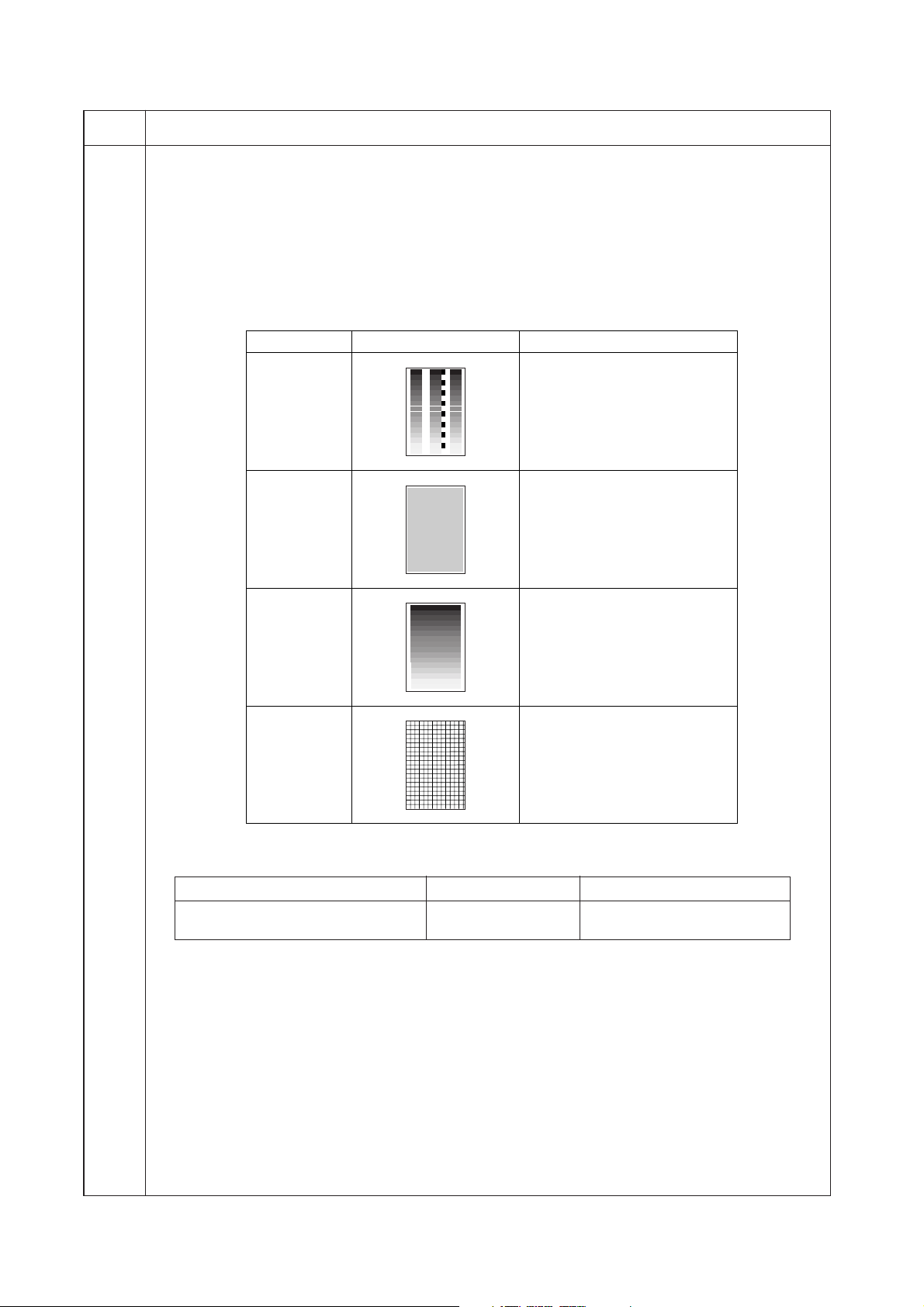
2FT-1
Maintenance
item No.
U089 Outputting a MIP-PG pattern
Description
Selects and outputs the MIP-PG pattern created in the machine.
Purpose
When performing respective image printing adjustments, used to check the machine status apart from that of
the scanner with a non-scanned output MIP-PG pattern.
Method
1. Press the start key. The screen for selecting an item is displayed.
2. Select the MIP-PG pattern to be output using the up/down cursor keys.
Display
GRAYSCALE To check the laser scanner unit
MONO-LEVE To check the drum quality.
Description
PG pattern to be output Purpose
engine output characteristics.
256-LEVEL To check resolution
reproducibility in printing.
1 DOT-LEVE To check fine line reproducibility.
To adjust the position of the laser
scanner unit (lateral squareness)
3. To change the output conditions of MONO-LEVEL and 1dot-LEVEL, use the left/right cursor keys to
change the preset values and press the start key to register the setting.
Display Setting range Initial setting
Output density of MONO-LEVEL 0 or 35 0
1dot-LEVEL 0 to 21 0
4. Press the interrupt key. The copy mode screen is displayed.
5. Press the start key. A MIP-PG pattern is output.
Completion
Press the stop/clear key at the screen for selecting an item. The screen for maintenance item No. is displayed.
1-4-22
Page 89

2FT-1
Maintenance
item No.
U092 Adjusting the scanner automatically
Description
Makes auto scanner adjustments in the order below using the specified original.
• Adjusting the scanner center line (U067)
• Adjusting the scanner leading edge registration (U066)
• Adjusting scanner magnification in the auxiliary direction (U065)
When this maintenance item is performed, the settings in U065, U066 and U067 are also changed.
Purpose
Used to make respective auto adjustments for the scanner.
Method
1. Place the specified original (P/N: 2A068021) on the contact glass.
2. Press the start key. The screen for executing is displayed.
3. Press the start key. Auto adjustment starts. When adjustment is complete, each adjusted value is
displayed.
Display Description
SCN CENTER Scanner center line
SCN TIMING Scanner leading registration
SUB SCAN Scanner magnification in the auxiliary scanning direction
MAIN SCAN Scanner magnification in the main scanning direction
If a problem occurs during auto adjustment, DATA: XX (XX is replaced by an error code) is displayed and
operation stops. Should this happen, determine the details of the problem and either repeat the procedure
from the beginning, or adjust the remaining items manually by running the corresponding maintenance
items.
Completion
Press the stop/clear key after auto adjustment is complete. The screen for selecting a maintenance item No. is
displayed.
If the stop/clear key is pressed during auto adjustment, adjustment stops and no settings are changed.
Description
1-4-23
Page 90

2FT
Maintenance
item No.
U093 Setting the exposure density gradient
Description
Changes the exposure density gradient in manual density mode, depending on respective image modes (text,
text and photo, photo, text in fax mode, photo in fax mode).
Purpose
To set how the image density is altered by a change of one step in the manual density adjustment. Also used to
make copy image darker or lighter.
Start
1. Press the start key. The screen for selecting an item is displayed.
2. Select the image mode to be adjusted using the up/down cursor keys and press the start key. The screen
for the selected item is displayed.
Display Description
MIXED Density in text and photo mode
TEXT Density in text mode
PHOTO Density in photo mode
FAX TEXT Density in the text in fax mode
FAX PHOTO Density in the photo in fax mode
Setting: Density in text and photo mode
1. Select the item to be adjusted using the up/down cursor keys. The selected item is displayed in reverse.
2. Adjust the setting using the left/right cursor keys.
Display Description Setting range Initial setting
MIXED DARKER Change in density when manual 0 to 3 0
density is set dark
MIXED LIGHTER Change in density when manual 0 to 3 0
density is set light
Increasing the setting makes the change in density larger, and decreasing it makes the change smaller.
Description
Image density
Dark
Light
Light
Setting: 3
Set to LIGHTER
Set to DARKER
Center
Setting: 0
Density adjustment
Dark
Figure 1-4-4 Exposure density gradient
3. Press the start key. The value is set.
4. To return to the screen for selecting an item, press the stop/clear key.
Setting: Density in text mode
1. Select the item to be adjusted using the up/down cursor keys. The selected item is displayed in reverse.
2. Adjust the setting using the left/right cursor keys.
Display Description Setting range Initial setting
TEXT DARKER Change in density when manual 0 to 3 0
density is set dark
TEXT LIGHTER Change in density when manual 0 to 3 0
density is set light
Increasing the setting makes the change in density larger, and decreasing it makes the change smaller.
3. Press the start key. The value is set.
4. To return to the screen for selecting an item, press the stop/clear key.
1-4-24
Page 91
2FT
Maintenance
item No.
U093
Setting: Density in photo mode
1. Select the item to be adjusted using the up/down cursor keys. The selected item is displayed in reverse.
2. Adjust the setting using the left/right cursor keys.
3. Press the start key. The value is set.
4. To return to the screen for selecting an item, press the stop/clear key.
Setting: Density in the text in fax mode
1. Select the item to be adjusted using the up/down cursor keys. The selected item is displayed in reverse.
2. Adjust the setting using the left/right cursor keys.
3. Press the start key. The value is set.
4. To return to the screen for selecting an item, press the stop/clear key.
Setting: Density in the photo in fax mode
1. Select the item to be adjusted using the up/down cursor keys. The selected item is displayed in reverse.
2. Adjust the setting using the left/right cursor keys.
3. Press the start key. The value is set.
4. To return to the screen for selecting an item, press the stop/clear key.
Interrupt copy mode
While this maintenance item is being performed, copying from an original can be made in interrupt copy mode.
1. Press the interrupt key. The machine enters the interrupt copy mode.
2. Set the original and press the strat key.
Completion
Press the stop/clear key at the screen for selecting an item. The screen for selecting a maintenance item No. is
displayed.
Description
Display Description Setting range Initial setting
PHOTO DARKER Change in density when manual 0 to 3 0
density is set dark
PHOTO LIGHTER Change in density when manual 0 to 3 0
density is set light
Increasing the setting makes the change in density larger, and decreasing it makes the change smaller.
Display Description Setting range Initial setting
FAX TEXT DARKER Change in density when manual 0 to 4 2
density is set dark
FAX TEXT LIGHTER Change in density when manual 0 to 9 2
density is set light
Increasing the setting makes the change in density larger, and decreasing it makes the change smaller.
Display Description Setting range Initial setting
FAX PHOTO DARKER Change in density when manual 0 to 6 3
density is set dark
FAX PHOTO LIGHT. Change in density when manual 0 to 6 3
density is set light
Increasing the setting makes the change in density larger, and decreasing it makes the change smaller.
To return to the screen for setting, press the interrupt key.
1-4-25
Page 92

2FT
Maintenance
item No.
U099 Checking the original size detection
Description
Checks the operation of the original size detection sensor and sets the sensing threshold value.
Purpose
To adjust the sensitiveness of the sensor and size judgement time if the original size detection sensor
malfunctions frequently due to incident light or the like.
Start
1. Press the start key. The screen for selecting an item is displayed.
2. Select an item using the up/down cursor keys.
3. Press the start key. The screen for executing each item is displayed.
Display Description
DATA Displaying detection sensor transmission data
B/W LEVEL Setting detection sensor threshold value
Method to display the data for the sensor
1. Press the start key. The detection sensor transmission data is displayed.
Rear of machine
Center of machine
Front of machine
Description
Setting original size judgment time
: 123 123 123
: 123 123 123
: 255 255 255
Figure 1-4-5
2. To return to the screen for selecting an item, press the stop/clear key.
Setting
1. Select an item to be set using the up/down cursor keys.
Display Description Setting range Initial setting
LEVEL Detection sensor threshold value 0 to 255 170
WAIT TIME Original size judgment time* 0 to 100 30
A4R AREA Threshold value in the main scan direction 220 (mm)/ 240
for A4R detection 240 (mm)
ORG AREA Original size detection position display (mm) 0 to 350 –
SIZE Detected original size display 0 to 63 –
*Time from activation of the original detection switch (ODSW) to original size judgment
Method to set the detection threshold value
1. Adjust the preset value using the left/right cursor keys.
A larger value increases the sensor sensitivity, and a smaller value decreases it.
2. Press the start key. The value is set.
3. To return to the screen for selecting an item, press the stop/clear key.
Method to set the original size judgment time
1. Adjust the preset value using the left/right cursor keys.
A larger value increases the original size judgment time, and a smaller value decreases it.
2. Press the start key. The value is set.
3. To return to the screen for selecting an item, press the stop/clear key.
Completion
Press the stop/clear key at the screen for selecting an item. The screen for maintenance item No. is displayed.
1-4-26
Page 93
2FT-1
Maintenance
item No.
U100 Setting the main high voltage
Description
Performs the main charging. Also changes the setting of main charging copy quantity correction.
Purpose
To check main charging. Also used when reentering data after initializing the set data.
Start
1. Press the start key. The screen for selecting an item is displayed.
2. Select the item using the up/down cursor keys.
Display Description
MC ON Turning the main charger on
LASER ON/OFF Turning the main charger on and the laser scanner unit on and off
INTERVAL Main charging copy quantity correction, copy interval
COPY CNT Main charging copy quantity correction, copy quantity
MC ADJUST Main charging copy quantity correction, correction amount
Method for main charger output
1. Press the start key. The selected operation starts.
2. To stop operation, press the stop/clear key.
Setting the main charging copy quantity correction
1. Change the setting using the left/right cursor keys.
Display Setting Setting range Initial setting
INTERVAL Copy interval 1 to 255 (minute) 60
COPY CNT Copy quantity 1 to 255 (10 sheets) 50
MC ADJUST Correction amount 0 to 50 (bit) 10
Copy interval: Sets the time interval from the previous copying. If the time from the previous copying
exceeds this preset value, the copy quantity counter will be reset.
Copy quantity: Sets the copy quantity from which copy quantity correction starts. When the copy quantity
counter reaches this preset value, correction will start.
Correction amount: Sets the correction amount for copy quantity correction.
Set the values in the range from 5 to 120 minutes for copy interval, from 10 to 2,000 sheets for copy
quantity, and from 5 to 50 bits for correction amount.
2. Press the start key. The value is set.
Completion
Press the stop/clear key when main charger output stops while a selection item is displayed. The indication for
selecting a maintenance item No. appears.
Description
1-4-27
Page 94
2FT-1
Maintenance
item No.
U101 Setting the other high voltages
Description
Changes the developing bias voltage and transfer/separation voltage.
Purpose
To check the developing bias and the transfer/separation voltage or to take measures against drop of image
density or background fog.
Method
1. Press the start key. The screen for selecting an item is displayed.
2. Select the item to be set using the up/down cursor keys.
3. Press the start key. The screen for executing each item is displayed.
Display Description
DEV Setting the developing bias
TC Setting the transfer voltage
SC Setting the separation voltage
Setting the developing bias
1. Select the item to be set using the up/down cursor keys.
2. Change the setting using the left/right cursor keys.
Display Description Setting range Initial setting
BIAS Developing bias clock frequency 2 to 255 25
DUTY Developing bias clock duty 1 to 99 50
DEV DATA Developing bias control voltage 0 to 255 98
Increasing the BIAS setting makes the image lighter; decreasing it makes the image darker.
Increasing the DUTY setting makes the image lighter; decreasing it makes the image darker.
3. Press the start key. The value is set.
Setting the transfer voltage
1. Select the item to be set using the up/down cursor keys.
2. Change the setting using the left/right cursor keys.
Display Description Setting range Initial setting
TC DATA1 Transfer control voltage (large size) 0 to 255 155
TC DATA2 Transfer control voltage (small size) 0 to 255 166
OFF TIMING Transfer charging output OFF timing 0 to 255 29
ON TIMING Transfer charging output ON timing 0 to 255 28
3. Press the start key. The value is set.
Setting the separation voltage
1. Select the item to be set using the up/down cursor keys.
2. Change the setting using the left/right cursor keys.
Display Description Setting range Initial setting
SC SEL Separation control voltage 0 to 2 1
ON TIMING Separation charging output ON timing 0 to 255 27
OFF TIMING Separation charging output OFF timing 0 to 255 38
SC MODE 0:
3. Press the start key. The value is set.
Interrupt copy mode
While this maintenance item is being performed, copying from an original can be made in interrupt copy mode.
1. Press the interrupt key. The machine enters the interrupt copy mode.
2. Set the original and press the strat key.
To return to the screen for setting, press the interrupt key.
Completion
Press the stop/clear key at the screen for selecting an item. The screen for maintenance item No. is displayed.
Separation charging output is all over a paper
1: Separation charging output is only for the
leading edge and trailing edge of a paper.
Description
0 / 1 0
1-4-28
Page 95

2FT-1
Maintenance
item No.
U110 Checking/clearing the drum count
Description
Displays the drum counts for checking, clearing the figure.
Purpose
To check the drum status. Also used to clear the count after replacing the durm during regular maintenance.
Since the count was cleared before shipping, do not clear it when installing. A drum count value less than 150K,
however, cannot be cleared.
Method
1. Press the start key. The drum counter count is displayed.
2. Select the CLEAR using the up/down cursor keys.
If the counter value is 150K or less, CLEAR is not displayed.
3. Press the start key. The count is cleared, and the screen for selecting a maintenance item No. is displayed.
Completion
To exit the maintenance mode without changing the count, press the stop/clear key. The screen for selecting a
maintenance item No. is displayed.
U113 Performing drum refresh operation
Description
Executes drum refresh operation.
Purpose
To operate when a faulty image (black line, etc.) occurs.
Method
1. Set A3/11" x 17" paper on drawer 2.
2. Press the start key. The screen for executing is displayed.
3. Press the start key. Drum refresh operation starts.
4. To stop the operation, press the stop/clear key.
Completion
Press the stop/clear key when the operation stops. The screen for selecting a maintenance item No. is displayed.
U117 Checking the drum number
Description
Displays the drum number.
Purpose
To check the drum number.
Method
Press the start key. The drum number is displayed.
Completion
Press the stop/clear key. The screen for selecting a maintenance item No. is displayed.
U118 Displaying the drum history
Description
Displays the past record of machine number and the drum counter.
Purpose
To check the count value of machine number and the drum counter.
Method
1. Press the start key. The count value of machine number and the drum counter is displayed.
2. Change the screen using the left/right cursor keys. Past record of 5 cases is displayed.
Completion
Press the stop/clear key. The screen for selecting a maintenance item No. is displayed.
U130 Initial setting for the developer
Description
Replenishes toner to the developer unit to a certain level from the toner container that has been installed.
Purpose
To operate when installing the machine.
Method
1. Press the start key. The screen for executing is displayed.
2. Select the EXECUTE using the up/down cursor keys.
3. Press the start key. Installation of toner starts and time (minutes) is indicated until the installation ends.
4. When the installation is complete, FINISHED will be displayed if the installation is successful or NG will be
displayed if it has failed.
If NG is displayed, check to see if the toner container contains toner and to see if the toner container sensor
malfunctions and then try again.
Completion
Press the stop/clear key after operation is complete. The screen for selecting a maintenance item No. is displayed.
Description
1-4-29
Page 96
2FT-1
Maintenance
item No.
U135 Checking toner motor operation
Description
Drives toner motor.
Purpose
To check the operation of toner motor.
Start
1. Press the start key. The screen for selecting an item is displayed.
2. Select the item using the up/down cursor keys.
Display Description
MOTOR MOVING Turning the toner motor on
ON TIME Toner motor on time
Method for toner motor on
1. Press the start key. The operation starts.
2. To stop operation, press the stop/clear key.
Setting for toner motor on time
1. Change the setting using the left/right cursor keys.
Descrition Setting range Initial setting
Toner motor on time 1 to +10 (s) 3
2. Press the start key. The value is set.
Completion
Press the stop key after operation stops. The screen for selecting a maintenance item No. is displayed.
U144 Setting toner loading operation
Description
Sets toner loading operation after completion of copying.
Purpose
To set whether or not toner is loaded on the drum after low density copying. Normally no change is necessary
from the initial setting.
Method
Press the start key. The screen for selecting an item is displayed.
Setting
1. Select either ON or OFF using the up/down cursor keys. The selected item is displayed in reverse.
Display Description
ON Toner loaded
OFF Toner not loaded
Initial setting: OFF
2. Press the start key. The value is set.
Description
1-4-30
Available only when the mode is turned on.
3. Select the item using the up/down cursor keys.
4. Change the setting using the left/right cursor keys.
Display Description Setting range Initial setting
COUNT Count number of sheets 1 to 50 5
PERCENT Printing ratio 10 to 40 30
Example
When COUNT is 5 and PERCENT is 30, take the average in every five sheets, and perform the toner
loading operation when the printing ratio is 3% or less.
5. Press the start key. The value is set.
Completion
Press the stop/clear key. The screen for selecting a maintenance item No. is displayed.
Page 97
2FT
Maintenance
item No.
U157 Checking/clearing the developing drive time
Description
Displays the developing drive time for checking, clearing or changing a figure.
Purpose
To check the developing drive time. Also used to clear the count after replacing the developing unit.
Method
Press the start key. The developing drive time is displayed in minutes.
Clearing
1. Select the CLEAR using the up/down cursor keys.
2. Press the start key. The time is cleared, and the screen for selecting a maintenance item No. is displayed.
Setting
1. Enter a seven-digit drive time (in minutes) using the numeric keys.
2. Press the start key. The time is set, and the screen for selecting a maintenance item No. is displayed.
Completion
To exit this maintenance item without changing the time, press the stop/clear key. The screen for selecting a
maintenance item No. is displayed.
U158 Checking the developing count
Description
Displays the developing count for checking a figure.
Purpose
To check the developing count.
Method
Press the start key. The developing count is displayed.
Completion
Press the stop/clear key. The screen for selecting a maintenance item No. is displayed.
U161 Setting the fixing control temperature
Description
Changes the fixing control temperature.
Purpose
Normally no change is necessary. However, can be used to prevent curling or creasing of paper, or solve a
fixing problem on thick paper.
Setting
1. Press the start key. The screen for selecting an item is displayed.
2. Select the item to be set using the up/down cursor keys. The screen for executing each item is displayed.
3. Change the setting using the left/right cursor keys.
Display Description Setting range Initial setting
1ST TEMP Primary stabilization fixing temperature 120 to 185 (°C) 152
2ND TEMP Secondary stabilization fixing temperature 120 to 185 (°C) 170
COPY TEMP1 Copying operation temperature 1 160 to 220 (°C) 180
COPY TEMP2 Copying operation temperature 2 160 to 220 (°C) 190
COPY CNT Number of sheets for fixing control 1 to 99 5
THICK CNT Number of sheets for fixing control (thick paper) 1 to 99 30
Copying operation temperature 1: Temperature in copying operation at the start of copying
Copying operation temperature 2: Temperature in copying operation after the specified number of sheets
for fixing control have passed
Number of sheets for fixing control: The number of sheets to be counted for switching from copying
operation temperature 1 to copying operation temperature 2
The temperatures are to be set such that Secondary stabilization
4. Press the start key. The value is set.
Completion
Press the stop/clear key. The screen for selecting a maintenance item No. is displayed.
Description
>
Primary stabilization.
=
1-4-31
Page 98

2FT-1
Maintenance
item No.
U162 Stabilizing fixing forcibly
Description
Stops the stabilization fixing drive forcibly, regardless of fixing temperature.
Purpose
To forcibly stabilize the machine before the fixing section reaches stabilization temperature.
Method
1. Press the start key. The screen for executing is displayed.
2. Press the start key. The forced stabilization mode is entered, and stabilization operation stops regardless
of fixing temperature. The screen for selecting a maintenance item No. is displayed.
To exit the forced stabilization mode, turn the power off and on.
Completion
To exit this maintenance item without executing forced fixing stabilization, press the stop/clear key.The screen
for selecting a maintenance item No. is displayed.
U163 Resetting the fixing problem data
Description
Resets the detection of a service call code indicating a problem in the fixing section.
Purpose
To prevent accidents due to an abnormally high fixing temperature.
Method
1. Press the start key. The screen for executing is displayed.
2. Select the EXECUTE using the up/down cursor keys. The selected item is displayed in reverse.
3. Press the start key. The fixing problem data is initialized.
Completion
Press the stop/clear key. The screen for selecting a maintenance item No. is displayed.
U167 Checking the fixing counts
Description
Displays the fixing counts.
Purpose
To check fixing counts.
Method
Press the start key. The fixing counts are displayed.
Completion
Press the stop/clear key. The screen for selecting a maintenance item No. is displayed.
U199 Checking the fixing temperature
Description
Displays the fixing temperature, the ambient temperature and the absolute humidity.
Purpose
To check the fixing temperature, the ambient temperature and the absolute humidity.
Method
Press the start key. The fixing temperature and ambient temperature are displayed in centigrade (°C) and the
absolute humidity is displayed in percentage (%).
Display Description
FIX TEMP Fixing temperature (°C)
SURROUND TEMP Ambient temperature (°C)
HUMIDITY Absolute humidity (%)
Description
1-4-32
Completion
Press the stop/clear key. The screen for selecting a maintenance item No. is displayed.
Page 99

2FT
Maintenance
item No.
U200 Turning all LEDs on
Description
Turns all the LEDs on the operation panel on.
Purpose
To check if all the LEDs on the operation panel light.
Method
Press the start key. All the LEDs on the operation panel light.
Press the stop/clear key or wait for 10 s. The LEDs turns off, and the screen for selecting a maintenance item
No. is displayed.
U202 Setting the KMAS host monitoring system
Description
Initializes or operates the KMAS host monitoring system.
This is an optional device which is currently supported only by Japanese specification machines, so no setting
is necessary.
U203 Checking DP operation
Description
Simulates the original conveying operation separately in the optional DP.
Purpose
To check the DP.
Method
1. Press the start key. The screen for selecting an item is displayed.
2. Place an original in the DP if running this simulation with paper.
3. Select the item to be operated using the up/down cursor keys. The selected item is displayed in reverse.
Display Operation
ADP With paper, single-sided original
RADP With paper, double-sided original
ADP (NON-P) Without paper, single-sided original (continuous operation)
RADP (NON-P) Without paper, double-sided original (continuous operation)
4. Press the start key. The operation starts.
5. To stop continuous operation, press the stop/clear key.
Completion
Press the stop/clear key when the operation stops. The screen for selecting a maintenance item No. is
displayed.
Description
1-4-33
Page 100

2FT-1
Maintenance
item No.
U204 Setting the presence or absence of a key card or key counter
Description
Sets the presence or absence of the optional key card or key counter.
Purpose
To run this maintenance item if a key card or key counter is installed.
Setting
1. Press the start key. The screen for selecting an item is displayed
2. Select the optional counter to be installed using the up/down cursor keys. The selected counter is
displayed in reverse.
Display Description
OFF None
KEY-CARD The key card is installed
KEY-COUNTER The key counter is installed
3. Press the start key. The setting is set and the screen for selecting a maintenance item No. is displayed.
Completion
Press the stop/clear key. The screen for selecting a maintenance item No. is displayed.
U207 Checking the operation panel keys
Description
Checks operation of the operation panel keys.
Purpose
To check operation of all the keys and LEDs on the operation panel.
Method
1. Press the start key. The screen for executing is displayed.
2. COUNT1 is displayed and the leftmost LED on the operation panel lights.
3. As the keys lined up in the same line as the lit indicator are pressed in the order from the top to the bottom,
the figure shown on the touch panel increases in increments of 1. When all the keys in that line are pressed
and if there are any LEDs corresponding to the keys in the line on the immediate right, the top LED in that
line will light.
4. When all the keys on the operation panel have been pressed, all the LEDs light for up to 10 seconds.
5. When the LEDs go off, press the start key. All the LEDs light for 10 seconds again.
Completion
Press the stop/clear key. The screen for selecting a maintenance item No. is displayed.
U233 Setting the ejection limit of the job separator
Description
When an optional job separator is installed, whether the limit of ejection to the job separator is 50 sheets for A3/
11" x 17" and 100 sheets for other sizes or 100 sheets for all sizes is set.
Purpose
To be set according to user request.
Method
Press the start key. The screen for selecting an item is displayed.
Setting
1. Select the item using the up/down cursor keys.
Display Description
MODE0 All size is limited to 100 sheets.
MODE1 A3/11" × 17" is limited to 50 sheets
Initial setting: MODE0
3. Press the start key. The setting is set, and the screen for selecting a maintenance item No. is displayed.
Completion
Press the stop/clear key. The screen for selecting a maintenance item No. is displayed.
Description
1-4-34
 Loading...