

Page 1

SERVICE
MANUAL
Published in Oct.’00
842AV110
Page 2

CAUTION
Danger of explosion if battery is incorrectly replaced. Replace only with the same or equivalent
type recommended by the manufacturer. Dispose of used batteries according to the
manufacturer’s instructions.
CAUTION
Double-pole/neutral fusing.
Page 3

Safety precautions
This booklet provides safety warnings and precautions for our service personnel to ensure the safety of
their customers, their machines as well as themselves during maintenance activities. Service personnel
are advised to read this booklet carefully to familiarize themselves with the warnings and precautions
described here before engaging in maintenance activities.
Page 4
Safety warnings and precautions
Various symbols are used to protect our service personnel and customers from physical danger and
to prevent damage to their property. These symbols are described below:
DANGER: High risk of serious bodily injury or death may result from insufficient attention to or incorrect
compliance with warning messages using this symbol.
WARNING:Serious bodily injury or death may result from insufficient attention to or incorrect compliance
with warning messages using this symbol.
CAUTION: Bodily injury or damage to property may result from insufficient attention to or incorrect
compliance with warning messages using this symbol.
Symbols
The triangle ( ) symbol indicates a warning including danger and caution. The specific point
of attention is shown inside the symbol.
General warning.
Warning of risk of electric shock.
Warning of high temperature.
indicates a prohibited action. The specific prohibition is shown inside the symbol.
General prohibited action.
Disassembly prohibited.
indicates that action is required. The specific action required is shown inside the symbol.
General action required.
Remove the power plug from the wall outlet.
Always ground the copier.
Page 5
1. Installation Precautions
WARNING
• Do not use a power supply with a voltage other than that specified. Avoid multiple connections to
one outlet: they may cause fire or electric shock. When using an extension cable, always check
that it is adequate for the rated current. ............................................................................................
• Connect the ground wire to a suitable grounding point. Not grounding the copier may cause fire or
electric shock. Connecting the earth wire to an object not approved for the purpose may cause
explosion or electric shock. Never connect the ground cable to any of the following: gas pipes,
lightning rods, ground cables for telephone lines and water pipes or faucets not approved by the
proper authorities. .............................................................................................................................
CAUTION:
• Do not place the copier on an infirm or angled surface: the copier may tip over, causing injury. .....
• Do not install the copier in a humid or dusty place. This may cause fire or electric shock. ..............
• Do not install the copier near a radiator, heater, other heat source or near flammable material.
This may cause fire. ..........................................................................................................................
• Allow sufficient space around the copier to allow the ventilation grills to keep the machine as cool
as possible. Insufficient ventilation may cause heat buildup and poor copying performance. ..........
• Always handle the machine by the correct locations when moving it. ..............................................
• Always use anti-toppling and locking devices on copiers so equipped. Failure to do this may
cause the copier to move unexpectedly or topple, leading to injury..................................................
• Avoid inhaling toner or developer excessively. Protect the eyes. If toner or developer is
accidentally ingested, drink a lot of water to dilute it in the stomach and obtain medical attention
immediately. If it gets into the eyes, rinse immediately with copious amounts of water and obtain
medical attention. ..............................................................................................................................
• Advice customers that they must always follow the safety warnings and precautions in the copier’s
instruction handbook. ........................................................................................................................
Page 6
2. Precautions for Maintenance
WARNING
• Always remove the power plug from the wall outlet before starting machine disassembly...............
• Always follow the procedures for maintenance described in the service manual and other related
brochures. .........................................................................................................................................
• Under no circumstances attempt to bypass or disable safety features including safety
mechanisms and protective circuits. .................................................................................................
• Always use parts having the correct specifications...........................................................................
• Always use the thermostat or thermal fuse specified in the service manual or other related
brochure when replacing them. Using a piece of wire, for example, could lead to fire or other
serious accident. ...............................................................................................................................
• When the service manual or other serious brochure specifies a distance or gap for installation of a
part, always use the correct scale and measure carefully. ...............................................................
• Always check that the copier is correctly connected to an outlet with a ground connection. ............
• Check that the power cable covering is free of damage. Check that the power plug is dust-free. If
it is dirty, clean it to remove the risk of fire or electric shock. ............................................................
• Never attempt to disassemble the optical unit in machines using lasers. Leaking laser light may
damage eyesight. ..............................................................................................................................
• Handle the charger sections with care. They are charged to high potentials and may cause
electric shock if handled improperly. .................................................................................................
CAUTION
• Wear safe clothing. If wearing loose clothing or accessories such as ties, make sure they are
safely secured so they will not be caught in rotating sections...........................................................
• Use utmost caution when working on a powered machine. Keep away from chains and belts. .......
• Handle the fixing section with care to avoid burns as it can be extremely hot. .................................
• Check that the fixing unit thermistor, heat and press rollers are clean. Dirt on them can cause
abnormally high temperatures...........................................................................................................
• Do not remove the ozone filter, if any, from the copier except for routine replacement....................
Page 7
• Do not pull on the AC power cord or connector wires on high-voltage components when removing
them; always hold the plug itself. ......................................................................................................
• Do not route the power cable where it may be stood on or trapped. If necessary, protect it with a
cable cover or other appropriate item. ..............................................................................................
• Treat the ends of the wire carefully when installing a new charger wire to avoid electric leaks........
• Remove toner completely from electronic components. ...................................................................
• Run wire harnesses carefully so that wires will not be trapped or damaged. ...................................
• After maintenance, always check that all the parts, screws, connectors and wires that were
removed, have been refitted correctly. Special attention should be paid to any forgotten
connector, trapped wire and missing screws. ..................................................................................
• Check that all the caution labels that should be present on the machine according to the
instruction handbook are clean and not peeling. Replace with new ones if necessary. ...................
• Handle greases and solvents with care by following the instructions below: ....................................
· Use only a small amount of solvent at a time, being careful not to spill. Wipe spills off completely.
· Ventilate the room well while using grease or solvents.
· Allow applied solvents to evaporate completely before refitting the covers or turning the main
switch on.
· Always wash hands afterwards.
• Never dispose of toner or toner bottles in fire. Toner may cause sparks when exposed directly to
fire in a furnace, etc...........................................................................................................................
• Should smoke be seen coming from the copier, remove the power plug from the wall outlet
immediately. ......................................................................................................................................
3. Miscellaneous
WARNING
• Never attempt to heat the drum or expose it to any organic solvents such as alcohol, other than
the specified refiner; it may generate toxic gas. ................................................................................
Page 8

CONTENTS
1-1 Specifications
1-1-1 Specifications ....................................................................................................................................... 1-1-1
1-1-2 Parts names and their functions ........................................................................................................... 1-1-5
(1) Copier ............................................................................................................................................. 1-1-5
(2) Operation panel .............................................................................................................................. 1-1-6
1-1-3 Machine cross section .......................................................................................................................... 1-1-8
1-1-4 Drive system ........................................................................................................................................ 1-1-9
(1) Drive system 1 (optical section) ...................................................................................................... 1-1-9
(2) Drive system 2 (drive motor drive train) ........................................................................................ 1-1-10
1-2 Handling Precautions
1-2-1 Drum .................................................................................................................................................... 1-2-1
1-2-2 Developer and toner ............................................................................................................................. 1-2-1
1-2-3 Installation environment ....................................................................................................................... 1-2-1
1-3 Installation
1-3-1 Unpacking and installation ................................................................................................................... 1-3-1
(1) Installation procedure ..................................................................................................................... 1-3-1
1-3-2 Setting initial copy modes .................................................................................................................. 1-3-13
1-3-3 Copier management ........................................................................................................................... 1-3-14
(1) Using the copier management mode (15 cpm copier) .................................................................. 1-3-14
(2) Setting department management items ........................................................................................ 1-3-15
(3) Copy default ................................................................................................................................. 1-3-15
(4) Using the copier management mode (20 cpm copier) .................................................................. 1-3-18
(5) Setting department management items ........................................................................................ 1-3-19
(6) Copy default ................................................................................................................................. 1-3-19
(7) Machine default ............................................................................................................................ 1-3-20
(8) Language ...................................................................................................................................... 1-3-21
1-3-4 Installing the key counter (option) ...................................................................................................... 1-3-22
1-3-5 Installing the original size detection sensor
(option for the metric specifications of the 15 cpm copier only) .......................................................... 1-3-24
1-3-6 Installing the drawer heater (option) ................................................................................................... 1-3-25
2AV/X
1-4 Maintenance Mode
1-4-1 Maintenance mode ............................................................................................................................... 1-4-1
(1) Executing a maintenance item ....................................................................................................... 1-4-1
(2) Maintenance mode item list (for 20 cpm copier) ............................................................................. 1-4-2
(3) Contents of maintenance mode items (for 20 cpm copier) ............................................................. 1-4-5
(4) Maintenance mode item list (for 15 cpm copier) ........................................................................... 1-4-53
(5) Contents of maintenance mode items (for 15 cpm copier) ........................................................... 1-4-56
1-5 Troubleshooting
1-5-1 Paper misfeed detection ...................................................................................................................... 1-5-1
(1) Paper misfeed indication ................................................................................................................ 1-5-1
(2) Paper misfeed detection conditions ................................................................................................ 1-5-3
(3) Paper misfeeds ............................................................................................................................... 1-5-8
1-5-2 Self-diagnosis ..................................................................................................................................... 1-5-12
(1) Self-diagnostic function ................................................................................................................ 1-5-12
(2) Self-diagnostic codes ................................................................................................................... 1-5-12
1-5-3 Image formation problems ................................................................................................................. 1-5-17
(1) No image appears (entirely white). ............................................................................................... 1-5-18
(2) No image appears (entirely black). ............................................................................................... 1-5-18
(3) Image is too light. ......................................................................................................................... 1-5-19
(4) Background is visible. ................................................................................................................... 1-5-19
(5) A white line appears longitudinally. .............................................................................................. 1-5-19
1-1-1
Page 9

2AV/X
(6) A black line appears longitudinally. .............................................................................................. 1-5-20
(7) A black line appears laterally. ....................................................................................................... 1-5-20
(8) One side of the copy image is darker than the other. ................................................................... 1-5-20
(9) Black dots appear on the image. .................................................................................................. 1-5-21
(10) Image is blurred. ........................................................................................................................... 1-5-21
(11) The leading edge of the image is consistently misaligned with the original. ................................ 1-5-21
(12) The leading edge of the image is sporadically misaligned with the original. ................................ 1-5-22
(13) Paper creases. ............................................................................................................................. 1-5-22
(14) Offset occurs. ............................................................................................................................... 1-5-22
(15) Image is partly missing. ................................................................................................................ 1-5-23
(16) Fixing is poor. ............................................................................................................................... 1-5-23
(17) Image is out of focus. ................................................................................................................... 1-5-23
(18) Image center does not align with the original center. ................................................................... 1-5-23
(19) Image is not square. ..................................................................................................................... 1-5-24
(20) Image contrast is low (carrier scattering) ...................................................................................... 1-5-24
1-5-4 Electrical problems ............................................................................................................................. 1-5-25
(1) The machine does not operate when the main switch is turned on. ............................................. 1-5-25
(2) The drive motor does not operate (C200). ................................................................................... 1-5-25
(3) The scanner motor does not operate. .......................................................................................... 1-5-25
(4) The toner feed motor does not operate. ....................................................................................... 1-5-25
(5) Cooling fan motor 1 does not operate. ......................................................................................... 1-5-25
(6) Cooling fan motor 2 does not operate. ......................................................................................... 1-5-25
(7) Cooling fan motor 3 does not operate. ......................................................................................... 1-5-26
(8) The drawer drive motor does not operate. ................................................................................... 1-5-26
(9) The registration clutch does not operate. ..................................................................................... 1-5-26
(10) The upper paper feed clutch does not operate. ............................................................................ 1-5-26
(11) The lower paper feed clutch does not operate. ............................................................................ 1-5-26
(12) Paper feed clutch (ST)1 does not operate. ................................................................................... 1-5-26
(13) Paper feed clutch (ST)2 does not operate. ................................................................................... 1-5-26
(14) The bypass paper feed clutch does not operate. ......................................................................... 1-5-26
(15) The cleaning lamp does not turn on. ............................................................................................ 1-5-26
(16) The exposure lamp does not turn on. ........................................................................................... 1-5-27
(17) The exposure lamp does not turn off. ........................................................................................... 1-5-27
(18) The fixing heater does not turn on (C610). ................................................................................... 1-5-27
(19) The fixing heater does not turn off. ............................................................................................... 1-5-27
(20) Main charging is not performed (C510). ....................................................................................... 1-5-27
(21) Transfer charging is not performed. ............................................................................................. 1-5-27
(22) No developing bias is output. ....................................................................................................... 1-5-27
(23) The original size is not detected. .................................................................................................. 1-5-27
(24) The original size is not detected correctly. ................................................................................... 1-5-28
(25) The message requesting paper to be loaded is shown when paper is present
in the upper drawer. ...................................................................................................................... 1-5-28
(26) The message requesting paper to be loaded is shown when paper is present
in the lower drawer. ...................................................................................................................... 1-5-28
(27) The message requesting paper to be loaded is shown when paper is present
on the bypass tray. ....................................................................................................................... 1-5-28
(28) The size of paper in the upper drawer is not displayed correctly. ................................................ 1-5-28
(29) The size of paper in the lower drawer is not displayed correctly. ................................................. 1-5-29
(30) The printing width of the paper on the bypass tray is not detected correctly. ............................... 1-5-29
(31) A paper jam in the paper feed, paper conveying or fixing section is indicated
when the main switch is turned on. .............................................................................................. 1-5-29
(32) The message requesting covers to be closed is displayed when the front cover,
paper conveying unit and lower drawer left cover are closed. ...................................................... 1-5-29
(33) Others. .......................................................................................................................................... 1-5-29
1-5-5 Mechanical problems ......................................................................................................................... 1-5-30
(1) No primary paper feed. ................................................................................................................. 1-5-30
(2) No secondary paper feed. ............................................................................................................ 1-5-30
(3) Skewed paper feed. ...................................................................................................................... 1-5-30
1-1-2
Page 10

(4) The scanner does not travel. ........................................................................................................ 1-5-30
(5) Multiple sheets of paper are fed at one time.................................................................................. 1-5-30
(6) Paper jams. .................................................................................................................................. 1-5-30
(7) Toner drops on the paper conveying path. ................................................................................... 1-5-30
(8) Abnormal noise is heard. .............................................................................................................. 1-5-30
1-6 Assembly and Disassembly
1-6-1 Precautions for assembly and disassembly ......................................................................................... 1-6-1
(1) Precautions ..................................................................................................................................... 1-6-1
(2) Running a maintenance item .......................................................................................................... 1-6-2
1-6-2 Paper feed section ............................................................................................................................... 1-6-3
(1) Detaching and refitting the upper and lower paper feed pulleys .................................................... 1-6-3
(2) Detaching and refitting the bypass paper feed pulley ..................................................................... 1-6-6
(3) Detaching and refitting the left registration cleaner assembly ........................................................ 1-6-8
(4) Detaching and refitting the right registration cleaner assembly ...................................................... 1-6-8
(5) Detaching and refitting the bypass paper width switch ................................................................... 1-6-9
(6) Adjustment after roller and clutch replacement ............................................................................ 1-6-10
(6-1) Adjusting the leading edge registration of image printing .................................................... 1-6-10
(6-2) Adjusting the leading edge registration for memory image printing ..................................... 1-6-12
(6-3) Adjusting the center line of image printing ........................................................................... 1-6-13
(6-4) Adjusting the margins for printing ........................................................................................ 1-6-15
(6-5) Adjusting the amount of slack in the paper .......................................................................... 1-6-17
1-6-3 Optical section .................................................................................................................................... 1-6-19
(1) Detaching and refitting the exposure lamp ................................................................................... 1-6-19
(2) Detaching and refitting the scanner wires .................................................................................... 1-6-20
(2-1) Detaching the scanner wires ............................................................................................... 1-6-20
(2-2) Fitting the scanner wires ...................................................................................................... 1-6-21
(3) Detaching and refitting the laser scanner unit .............................................................................. 1-6-24
(4) Adjusting the skew and vertical shifting of the laser scanner unit ................................................ 1-6-26
(4-1) Adjusting the skew of the laser scanner unit ....................................................................... 1-6-26
(4-2) Adjusting the vertical shifting of the laser scanner unit ........................................................ 1-6-27
(5) Detaching and refitting the ISU (reference) .................................................................................. 1-6-28
(6) Adjusting the position of the ISU (reference) ................................................................................ 1-6-30
(7) Adjusting the longitudinal squareness (reference) ....................................................................... 1-6-31
(8) Adjusting magnification of the scanner in the main scanning direction ........................................ 1-6-32
(9) Adjusting magnification of the scanner in the auxiliary scanning direction ................................... 1-6-34
(10) Adjusting the scanner leading edge registration ........................................................................... 1-6-36
(11) Adjusting the scanner center line ................................................................................................. 1-6-37
(12) Adjusting the margins for scanning an original on the contact glass ............................................ 1-6-38
1-6-4 Main charging section ........................................................................................................................ 1-6-40
(1) Detaching and refitting the charger assembly .............................................................................. 1-6-40
(2) Replacing the tungsten wire (reference) ....................................................................................... 1-6-41
1-6-5 Drum section ...................................................................................................................................... 1-6-43
(1) Detaching and refitting the drum .................................................................................................. 1-6-43
1-6-6 Developing section ............................................................................................................................. 1-6-44
(1) Adjusting the position of the doctor blade (reference) .................................................................. 1-6-44
1-6-7 Transfer section ................................................................................................................................. 1-6-45
(1) Detaching and refitting the transfer roller assembly ..................................................................... 1-6-45
1-6-8 Cleaning section ................................................................................................................................. 1-6-46
(1) Detaching and refitting the cleaning blade ................................................................................... 1-6-46
(2) Detaching and refitting the drum separation claw assemblies ..................................................... 1-6-47
(3) Detaching and refitting the cleaning lower seal assembly ............................................................ 1-6-47
1-6-9 Fixing section ..................................................................................................................................... 1-6-48
(1) Detaching and refitting the fixing unit ........................................................................................... 1-6-48
(2) Detaching and refitting the fixing unit thermistor .......................................................................... 1-6-49
(3) Detaching and refitting the heat roller separation claws ............................................................... 1-6-49
(4) Detaching and refitting the fixing heater ....................................................................................... 1-6-50
(5) Detaching and refitting the heat roller ........................................................................................... 1-6-51
(6) Detaching and refitting the press roller ......................................................................................... 1-6-53
1-1-3
2AV/X
Page 11

2AV/X
1-7 Requirements on PCB Replacement
1-7-1 Replacing the main PCB ...................................................................................................................... 1-7-1
1-7-2 Upgrading the firmware on the main PCB ............................................................................................ 1-7-3
1-7-3 Upgrading the firmware on the operation unit PCB (20 cpm copier only) ............................................ 1-7-5
1-7-4 Adjustment-free variable resistors (VR) ............................................................................................... 1-7-6
2-1 Mechanical construction
2-1-1 Paper feed section ............................................................................................................................... 2-1-1
2-1-2 Main charging section .......................................................................................................................... 2-1-4
2-1-3 Optical section ...................................................................................................................................... 2-1-6
(1) Original scanning ............................................................................................................................ 2-1-7
(2) Image printing ................................................................................................................................. 2-1-8
2-1-4 Developing section ............................................................................................................................. 2-1-10
(1) Formation of magnetic brush ........................................................................................................ 2-1-11
(2) Toner density detection by the toner sensor ................................................................................ 2-1-12
(3) Toner density control .................................................................................................................... 2-1-12
(4) Correcting the toner sensor control voltage .................................................................................. 2-1-13
(5) Correcting toner output voltage .................................................................................................... 2-1-14
2-1-5 Transfer and separation section ......................................................................................................... 2-1-15
2-1-6 Cleaning section ................................................................................................................................. 2-1-17
2-1-7 Charge erasing section ...................................................................................................................... 2-1-18
2-1-8 Fixing section ..................................................................................................................................... 2-1-19
2-2 Electrical Parts Layout
2-2-1 Electrical parts layout ........................................................................................................................... 2-2-1
(1) PCBs .............................................................................................................................................. 2-2-1
(2) Switches and sensors ..................................................................................................................... 2-2-2
(3) Motors ............................................................................................................................................. 2-2-4
(4) Other electrical components ........................................................................................................... 2-2-5
2-3 Operation of the PCBs
2-3-1 Power source PCB ............................................................................................................................... 2-3-1
2-3-2 Main PCB ............................................................................................................................................. 2-3-4
2-3-3 CCD PCB ........................................................................................................................................... 2-3-14
2-3-4 Laser diode PCB ................................................................................................................................ 2-3-15
2-4 Appendixes
Timing chart No. 1 .......................................................................................................................................... 2-4-1
Timing chart No. 2 .......................................................................................................................................... 2-4-2
Timing chart No. 3 .......................................................................................................................................... 2-4-3
Timing chart No. 4 .......................................................................................................................................... 2-4-4
Timing chart No. 5 .......................................................................................................................................... 2-4-5
Timing chart No. 6 .......................................................................................................................................... 2-4-6
Timing chart No. 7 .......................................................................................................................................... 2-4-7
Timing chart No. 8 .......................................................................................................................................... 2-4-8
Timing chart No. 9 .......................................................................................................................................... 2-4-9
Timing chart No. 10 ...................................................................................................................................... 2-4-10
Maintenance parts list................................................................................................................................... 2-4-11
Periodic maintenance procedures ................................................................................................................ 2-4-12
General connection diagram (1) ................................................................................................................... 2-4-15
General connection diagram (2) ................................................................................................................... 2-4-16
1-1-4
Page 12

1-1-1 Specifications
2AV/X
15 cpm copier
Type ............................................... Desktop
Copying system.............................. Indirect electrostatic system
Originals ......................................... Sheets and books
Maximum size: A3/11" × 17"
Original feed system ...................... Fixed
2
Copy paper..................................... Drawer: Plain paper (64 – 80 g/m
Bypass table: Plain paper (60 – 160 g/m
)
2
)
Special paper: Transparencies, tracing paper, colored paper, letterhead
and envelopes (when using the printer function only)
Note: Use the bypass table for special paper.
Copying sizes ................................. Maximum: A3/11" × 17"
1
Minimum: A6R /5
/2" × 81/2"/Folio (When the bypass table is used)
Magnification ratios ........................ Manual mode: 50 – 200%, 1% increments
Copy speed .................................... At 100% magnification in copy mode:
A4: 15 copies/min.
A4R: 10 copies/min.
A3: 8 copies/min.
B5: 15 copies/min.
B5R: 10 copies/min.
B4 (257 × 364 mm): 8 copies/min.
1
11" × 8
8
/2": 15 copies/min.
1
/2" × 11": 10 copies/min.
11" × 17": 8 copies/min.
1
/2" × 14": 8 copies/min.
8
At 100% magnification when the optional memory board is installed:
A4: 18 copies/min.
A4R: 12 copies/min.
A3: 9 copies/min.
B5: 18 copies/min.
B5R: 12 copies/min.
B4 (257 × 364 mm): 10 copies/min.
1
11" × 8
8
/2": 18 copies/min.
1
/2" × 11": 12 copies/min.
11" × 17": 9 copies/min.
81/2" × 14": 10 copies/min.
1
First copy time ................................ From 5 to 6 s (A4/11" × 8
/2", 100% magnification, upper drawer, ejection to the eject
tray)
Warm-up time................................. 30 s or less (room temperature 20°C/68°F, 65% RH)
In preheat/energy saver mode: 30 s or less (room temperature 20°C/68°F, 65% RH)
[priorty to power save]
In preheat/energy saver mode: 15 s or less (room temperature 20°C/68°F, 65% RH)
[priorty to recovery]
Paper feed system ......................... Automatic feed
Capacity:
Drawers: 250 sheets
Manual feed
Capacity:
Bypass: 50 sheets (A4, A4R, B5, B5R, A5R, B6R, A6R, 11" × 8
× 14")
25 sheets (A3, B4, Folio, 11" × 17", 81/2" × 14")
Continuous copying........................ 1 – 250 sheets
Photoconductor .............................. OPC (drum diameter 30 mm)
Charging system ............................ Single positive corona charging
Exposure light source..................... Semiconductor laser
Exposure scanning system ............ Polygon mirror
Developing system ......................... Dry, reverse developing (magnetic brush)
Developer: 2-component, ferrite carrier and N29T black toner
Toner density control: toner sensor
Toner replenishing: automatic from a toner cartridge
1
/2", 81/2" × 11", 51/2"
1-1
1-1-1
Page 13

1-1
2AV/X
Transfer system .............................Transfer roller
Fixing system ................................. Heat roller
Heat source: halogen heaters (850 W for 120 V specifications/910 W for 220-240 V
specifications)
Control temperature: 180°C/356°F (at normal ambient temperature)
Abnormally high temperature protection device: 140°C/284°F thermostat
Fixing pressure: 49 N
Charge erasing system .................. Exposure by cleaning lamp
Cleaning system............................. Cleaning blade
Scanning system ............................ Flat bed scanning by CCD image sensor
Resolution ...................................... 600 × 600 dpi
Light source.................................... Inert gas lamp
Dimensions .................................... 550 (W) × 560 (D) × 455 (H) mm
Weight ............................................Approx. 38 kg/83.6 lbs
Floor requirements ......................... 891 (W) × 560 (D) mm
Functions........................................ Self-diagnostics, preheat, automatic copy density control, original size detection*,
Power source ................................. 120 V AC, 60 Hz, 9 A
Power consumption........................ 1080 W (120V)
Options ........................................... STDF, drawer, job separator, original cover*, key counter, key card**, memory board,
5
/8" (W) × 221/16" (D) × 1715/16" (H)
21
550 (W) × 560 (D) × 498 (H) mm (for Asia and Oceania specifications)
41 kg/90.2lbs (for Asia and Oceania specifications)
1
/16" (W) × 221/16" (D)
35
automatic paper selection, automatic magnification selection, enlargement/reduction
copy, photo mode and department control
*Optional original size detection sensor is needed for 220-240 V specifications.
220 – 240 V AC, 50/60 Hz, 2.8 A
1080W (220 – 240V)
printer network board
*Standard for Asia and Oceania specifications.
**Optional for 120 V specifications only.
1-1-2
Page 14

20 cpm copier
2AV/X
Type ............................................... Desktop
Copying system.............................. Indirect electrostatic system
Originals ......................................... Sheets and books
Maximum size: A3/11" × 17"
Original feed system ...................... Fixed
2
Copy paper..................................... Drawer: Plain paper (64 – 80 g/m
Bypass table: Plain paper (60 – 160 g/m
)
2
)
Special paper: Transparencies, tracing paper, colored paper, letterhead
and envelopes (when using the printer function only)
Note: Use the bypass table for special paper.
Copying sizes ................................. Maximum: A3/11" × 17"
1
Minimum: A6R /5
/2" × 81/2"/Folio (When the bypass table is used)
Magnification ratios ........................ Manual mode: 50 – 200%, 1% increments
Auto copy mode: fixed ratios
Metric
1:1 ± 1.0%, 1:2.00/1:1.41/1:1.27/1:1.06/1:0.90/1:0.75/1:0.70/1:0.50
Inch
1:1 ± 1.0%, 1:2.00/1:1.54/1:1.29/1:1.21/1:0.78/1:0.77/1:0.64/1:0.50
Copy speed .................................... At 100% magnification in memory copy mode:
A4: 20 copies/min.
A4R: 13 copies/min.
A3: 10 copies/min.
B5: 20 copies/min.
B5R: 13 copies/min.
B4 (257 × 364 mm): 11 copies/min.
1
11" × 8
8
/2": 20 copies/min.
1
/2" × 11": 13 copies/min.
11" × 17": 10 copies/min.
1
/2" × 14": 11 copies/min.
8
First copy time ................................ From 5 to 6 s (A4/11" × 8
1
/2", 100% magnification, upper drawer, ejection to the eject
tray)
Warm-up time................................. 30 s or less (room temperature 20°C/68°F, 65% RH)
In preheat/energy saver mode: 30 s or less (room temperature 20°C/68°F, 65% RH)
[priorty to power save]
In preheat/energy saver mode: 15 s or less (room temperature 20°C/68°F, 65% RH)
[priorty to recovery]
Paper feed system ......................... Automatic feed
Capacity:
Drawers: 250 sheets
Manual feed
Capacity:
Bypass: 50 sheets (A4, A4R, B5, B5R, A5R, B6R, A6R, 11" × 8
14")
1
25 sheets (A3, B4, Folio, 11" × 17", 8
/2" × 14")
Continuous copying........................ 1 – 250 sheets
Photoconductor .............................. OPC (drum diameter 30 mm)
Charging system ............................ Single positive corona charging
Exposure light source..................... Semiconductor laser
Exposure scanning system ............ Polygon mirror
Developing system ......................... Dry, reverse developing (magnetic brush)
Developer: 2-component, ferrite carrier and N29T black toner
Toner density control: toner sensor
Toner replenishing: automatic from a toner cartridge
Transfer system .............................Transfer roller
Fixing system ................................. Heat roller
Heat source: halogen heaters (850 W for 120 V specifications, 910 W for 230-240 V
specifications)
Control temperature: 180°C/356°F (at normal ambient temperature)
Abnormally high temperature protection device: 140°C/284°F thermostat
Fixing pressure: 49 N
Charge erasing system .................. Exposure by cleaning lamp
1
/2", 81/2" × 11", 51/2" ×
1-1
1-1-3
Page 15

1-1
2AV/X
Cleaning system............................. Cleaning blade
Scanning system ............................ Flat bed scanning by CCD image sensor
Bit map memory ............................. 17.1 MB (standard)
Image storage memory .................. 46.9 MB (standard)
Resolution ...................................... 600 × 600 dpi
Light source.................................... Inert gas lamp
Dimensions .................................... 550 (W) × 603 (D) × 554 (H) mm
Weight ............................................Approx. 46.4 kg/102 lbs
Floor requirements ......................... 891 (W) × 603 (D) mm
Functions........................................ Self-diagnostics, preheat, automatic copy density control, original size detection,
Power source ................................. 120 V AC, 60 Hz, 9 A
Power consumption........................ 1080 W (120V)
Options ........................................... STDF, SRDF, drawer, duplex unit, job separator, original cover, finisher, key counter,
5
/8" (W) × 233/4" (D) × 2113/16" (H)
21
1
/6" (W) × 233/4" (D)
35
automatic paper selection, automatic magnification selection, enlargement/reduction
copy, fixed ratio selection, photo mode, margin copy, split copy, border erasing,
combine copy, sort copy, department control and language selection
220 – 240 V AC, 50/60 Hz, 2.8 A
1080W (220 – 240V)
key card*, printer network board, fax unit, network scanner
*Optional for 120 V specifications only.
1-1-4
Page 16
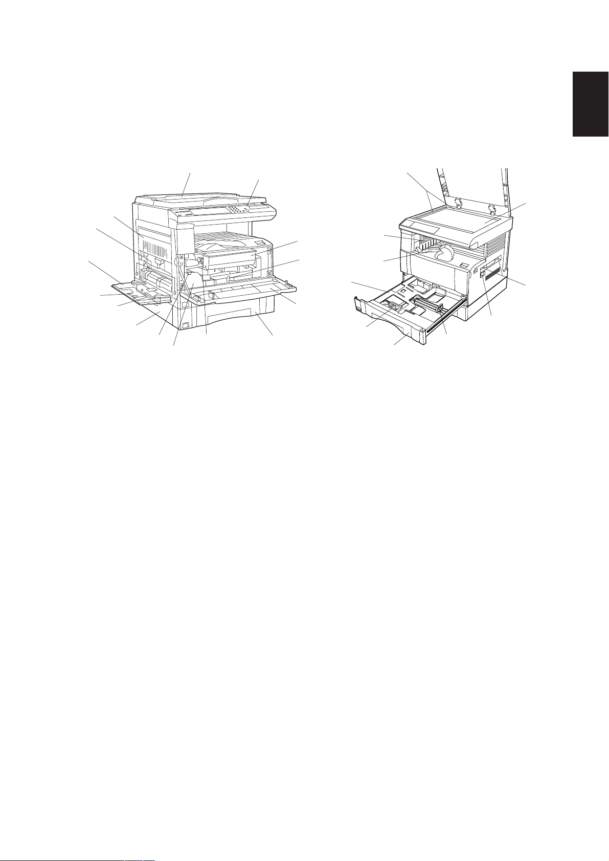
1-1-2 Parts names and their functions
2AV/X
(1) Copier
‹
4
6
3
5
›
0
9
1
!
2
&
7
8
@
¤
1-1
(
*
%
$
‹
#
⁄
)
^
Figure 1-1-1
1 Original cover (optional)*
2 Operation panel
3 Paper conveying unit
4 Multi-Bypass
5 Insert guides
6 Support tray
7 Toner cartridge
8 Toner cartridge release lever
9 Waste toner tank
0 Waste toner tank release lever
! Cleaning shaft
@ Front cover
# Main switch
$ Copy store section
% Ejection section
^ Upper drawer
& Lower drawer*
* Platen
( Original size scales
) Length adjustment plate
⁄ Width adjustment lever
¤ Drawer lift
‹ Handles for transport
› Lower drawer left cover*
2
1
2
*1: Standard for Asia and Oceania specifications
for the 15 cpm copier.
*2: Optional for 15 cpm copier.
1-1-5
Page 17
2AV/X
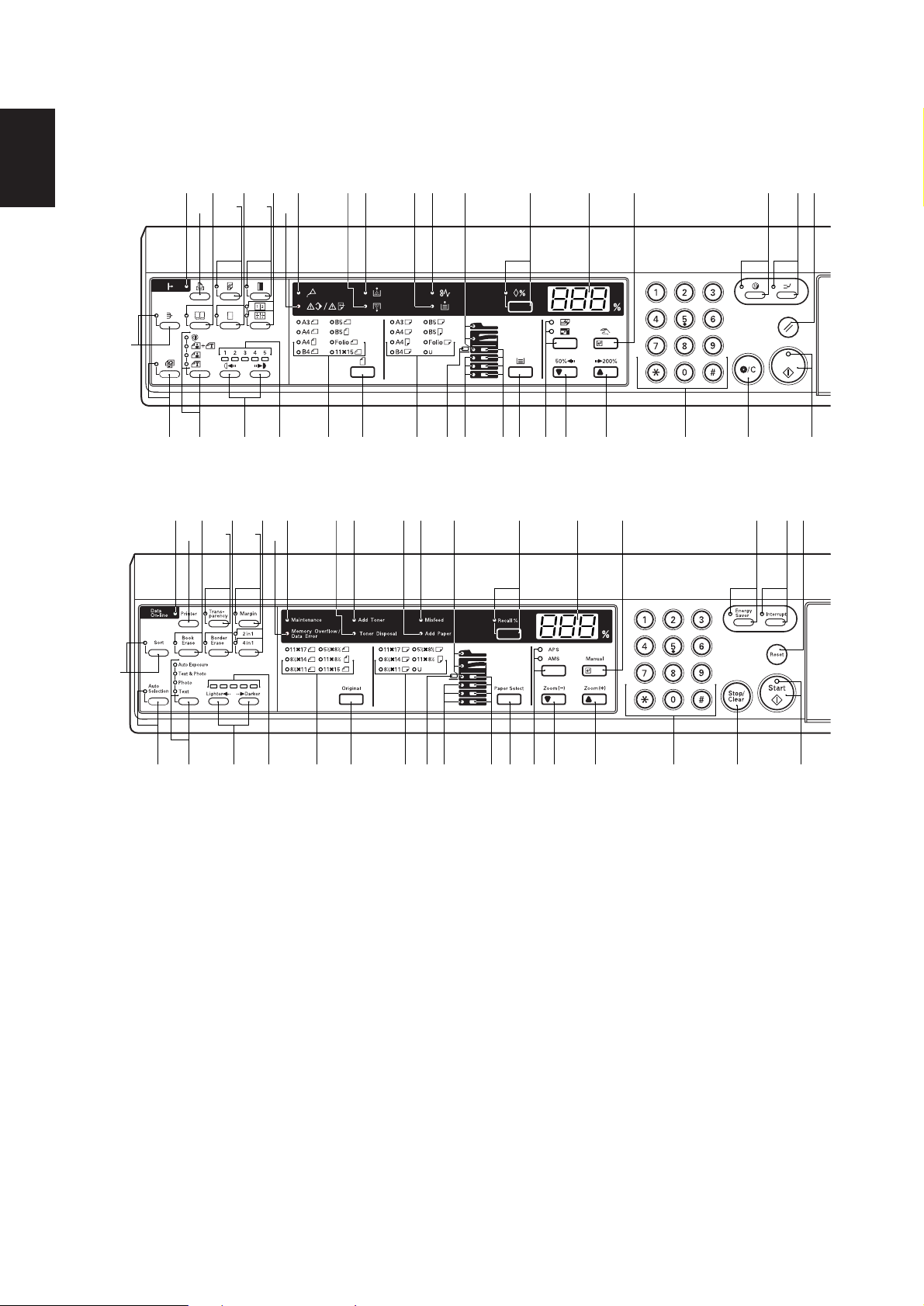
(2) Operation panel
15 cpm copier
1-1
Metric
Inch
‰
´
Á
Œ·‹
¤⁄ )( % @ 8 7 6
ˇ„‚›
°‡fifl*&^%$#!09321$
Á
´
Œ·‹ ¤ )( % @ 8 7 654⁄
ˇ„‚›
54
‰
°‡ fi fl * & ^$% $#!0 9 3 2 1
1 Start key (Indicator)
2 Stop/Clear key
3 Numeric keys
4 Reset key
5 Interrupt key (Indicator)
6 Energy Saver (preheat) key (Indicator)
7 Manual/Enter key
8 Copy quantity/magnification display
9 Zoom (+) key
0 Zoom (-) key
! Auto mode selection key/APS/AMS indicators
@ Recall key
# Paper Select key
$ Drawer select indicators
% Misfeed location indicators
^ Paper size indicators
& Original key
* Original size indicators
( Misfeed indicator
) Add Paper indicator
Figure 1-1-2
⁄ Add Toner indicator
¤ Toner Disposal indicator
‹ Maintenance indicator
› Memory Overflow/Data Error indicator
fi Copy exposure adjustment keys
fl Copy exposure indicators
‡ Image mode selection key/Auto Exposure/Text
& Photo/Photo/Text indicators
° Auto Selection key (Indicator)
· Layout key/2 in 1 indicator/4 in 1 indicator
‚ Margin key (Indicator)
ΠBorder Erase key (Indicator)
„ Transparency key (Indicator)
´ Book Erase key (Indicator)
‰ Sort key (Indicator)
ˇ Printer key
Á Data On-line indicator
1-1-6
Page 18
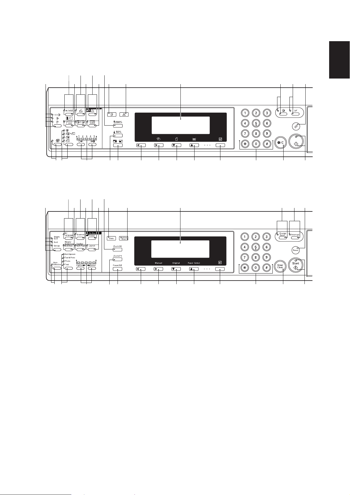
20 cpm copier
2AV/X
Metric
%*⁄‹
(¤›fl
$
‡fi ) ^& @ ! 0 9 8 6 5 1
Inch
%*⁄‹
(¤›fl
1-1
2347#
2347#$
‡fi ) ^ & @ ! 0 9 8 6 5 1
Figure 1-1-3
1 Start key (Indicator)
2 Reset key
3 Interrupt key (Indicator)
4 Energy Saver (preheat) key (Indicator)
5 Stop/Clear key
6 Numeric keys
7 Message display
8 Enter key
9 Paper Select/Cursor up key
0 Original/Cursor down key
! Manual/Cursor right key
@ Cursor left key
# Machine Error indicator
$ Data indicator
% Zoom (+) key
^ Zoom (–) key
& Preset R/E key
* On-line/Printer key (Indicator)
( Layout key (Indicator)
) Copy exposure adjustment keys/Copy
exposure indicators
⁄ Scanner key (Indicator)
¤ Duplex/Split Page key (Indicator)
‹ */Language key
› Margin/Border Erase/Book Erase key
(Indicator)
fi Copy quality selection key/Auto Exposure/Text
& Photo/Photo/Text indicators
fl Sort mode key/Staple Sort/Sort/Group
indicators
‡ Auto Selection key (Indicator)
1-1-7
Page 19
1-1
2AV/X
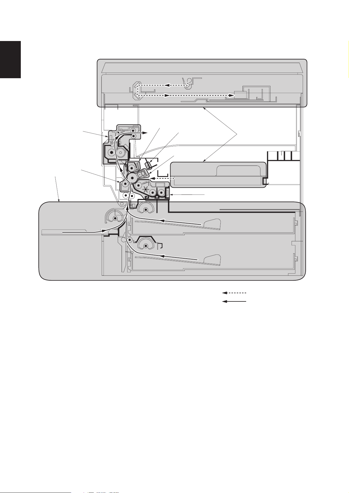
1-1-3 Machine cross section
1
8
5
6
2
7
3
4
Light path
Paper path
1-1-8
Figure 1-1-4 Machine cross section
1 Paper feed section
2 Main charging section
3 Optical section
4 Developing section
5 Transfer and paper conveying section
6 Cleaning section
7 Charge erasing section
8 Fixing section
Page 20

1-1-4 Drive system
2AV/X
(1) Drive system 1 (optical section)
8
1 Scanner motor gear
2 Gear 44/16
3 Gear 26
4 Scanner wire drum
7
Figure 1-1-5
5 Scanner wire
6 Scanner wire pulley
7 Scanner wire pulley
8 Scanner wire pulley
5
3
4
As viewed from machine front
6
1
2
1-1
1-1-9
Page 21
2AV/X
(2) Drive system 2 (drive motor drive train)
1-1
´
Œ
7
8
&
„
2
1
9
Î
^
3
—
‚
0
Í
‡
%
Å
4
5
·
fi
!
#
fl
ˆ
⁄
)
¨
Á
‰
ˇ
›
‹
6
*
(
¤
@
$
1 Drive motor gear
2 Gear 58/30
3 Gear 48/27
4 Gear 60
5 Drum gear
6 Transfer roller gear
7 Gear 52/30
8 Gear 32/16
9 Gear 32/16
0 Gear 20
! Gear 20
@ Gear 20
# Idle gear 16
$ Bypass paper feed clutch gear
% Gear 16
As viewed from machine rear
Figure 1-1-6
^ Upper paper feed clutch gear
& Gear 30
* Gear 26/14
( Gear 20
) Registration clutch gear
⁄ Gear 15
¤ Gear 18
‹ Gear 20
› Gear 34/23
fi Gear 24
fl Gear 15
‡ Spiral gear 17
— Blade thrust gear 21
· Gear 16
‚ Idle gear
”
Ø
ΠGear 19
„ Gear 23
´ Gear 23
‰ Gear 29
ˇ Fixing gear 19
Á Heat roller gear 35
¨ Idle gear
ˆ Gear 21
Ø Drawer drive motor gear*
” Gear 16/52*
Å Gear 18*
Í Gear 18*
Î Lower paper feed clutch gear*
1-1-10
* Optional for the 15 cpm copier/standard for the 20 cpm copier.
Page 22
2AV/X
1-2-1 Drum
Note the following when handling or storing the drum.
• When removing the image formation unit, never expose the drum surface to strong direct light.
• Keep the drum at an ambient temperature between –20°C/–4°F and 40°C/104°F and at a relative humidity not higher
than 85% RH. Avoid abrupt changes in temperature and humidity.
• Avoid exposure to any substance which is harmful to or may affect the quality of the drum.
• Do not touch the drum surface with any object. Should it be touched by hands or stained with oil, clean it.
• If the machine is left open for more than 5 minutes for maintenance, remove the drum and store it in the drum storage
bag (Part No. 78369020).
1-2-2 Developer and toner
Store the developer and toner in a cool, dark place. Avoid direct light and high humidity.
1-2-3 Installation environment
1. Temperature: 10 - 35°C/50 - 95°F
2. Humidity: 15 - 85%RH
3. Power supply: 120 V AC, 9 A
4. Power source frequency: 50 Hz ±0.3%/60 Hz ±0.3%
5. Installation location
• Avoid direct sunlight or bright lighting. Ensure that the photoconductor will not be exposed to direct sunlight or other
strong light when removing paper jams.
• Avoid extremes of temperature and humidity, abrupt ambient temperature changes, and hot or cold air directed onto
the machine.
• Avoid dust and vibration.
• Choose a surface capable of supporting the weight of the machine.
• Place the machine on a level surface (maximum allowance inclination: 1° ).
• Avoid air-borne substances that may adversely affect the machine or degrade the photoconductor, such as
mercury, acidic of alkaline vapors, inorganic gasses, NOx, SOx gases and chlorine-based organic solvents.
• Select a room with good ventilation.
6. Allow sufficient access for proper operation and maintenance of the machine.
Machine front: 1000 mm/39
Machine right: 700 mm/27
220 - 240 V AC, 2.8 A
3
/8" Machine rear: 100 mm/4"
5
/8" Machine left: 600 mm/235/8"
1-2
• 15 cpm copier
a: 576 mm/2211/16"
b: 873 mm/34
c: 555 mm/21"
d: 718 mm/28
e: 560 mm/22
f: 1183 mm/469/16"
g: 418 mm/7
7
3
1
1
/16"
/8"
/4"
/16"
eg
d
c
ab
f
Figure 1-2-1a Installation dimensions
1-2-1
Page 23
2AV/X
1-2
• 20 cpm copier
a: 675 mm/26
b: 873 mm/343/8"
c: 555 mm/21"
d: 718 mm/28
e: 603 mm/233/4"
f: 1218 mm/46
g: 418 mm/16
h: 951 mm/377/16"
9
1
7
/16"
/4"
9
/16"
/16"
eg
h
d
c
ab
f
Figure 1-2-1b Installation dimensions
1-2-2
Page 24
1-3-1 Unpacking and installation
(1) Installation procedure
Start
Unpack.
2AV/X
1-31-3
Remove the tapes.
Remove the pins holding light source units 1 and 2.
Install the optional devices.
Remove the image formation unit.
Load developer.
Release the cleaning blade.
Install a waste toner tank.
Adjust the fixing pressure.
Connect the power cord.
Carry out initial developer setting
(maintenance item U130).
Load paper.
Output an own-status report
(maintenance item U000).
Exit maintenance mode.
Install a toner cartridge.
Make test copies.
Completion of the machine installation.
1-3-1
Page 25
1-3
2AV/X
Light source unit 1 pins
Light source unit 2 pin
*The diagram shows the 20 cpm copier.
*The original cover is standard for Asia and Oceania specifications for the 15 cpm copier only.
Figure 1-3-1
1-3-2
Page 26
Unpack.
• 15 cpm copier
2AV/X
!
@
5
0
)
*(
4
7
9
1
4
8
^
%&
3
#
1-3
2
$
1 Copier
2 Outer case
3 Inner frame
4 Upper pads
5 Bottom pads
6 Bottom case
7 Skid
8 Bottom plate
9 Spacer*
0 Machine cover
! Original cover*
@ Plastic bag*
1
2
6
Figure 1-3-2a Unpacking
2
# Bar code labels
$ Hinge joint
% Instruction handbook
^ Plastic bag
& Business reply mail*
* Drawer spacers
( Drawer claw spacers
) Power cord
*1: 230 V specifications only.
*2: Asia and Oceania specifications
only.
*3: 120 V specifications only.
3
1-3-3
Page 27
1-3
2AV/X
• 20 cpm copier
9
4
8
@$
4
5
*
%^
1
#
&
7
6
Figure 1-3-2b Unpacking
3
0
2
!
1-3-4
1 Copier
2 Outer case
3 Inner frame
4 Upper pads
5 Bottom pads
6 Bottom case
7 Skid
8 Spacer*
9 Machine cover
0 Bar code labels
! Hinge joint
1
@ Instruction handbook
# Plastic bag
$ Business reply mail*
% Drawer spacers
^ Drawer claw spacers
& Rear cover spacer
* Power cord
*1: 230 V specifications only.
*2: 120 V specifications only.
2
Page 28
Remove the tapes.
1. Remove the tape holding the front cover and the
power cord, and remove the tape binding the
power cord.
2. Remove the tape holding the drawer.
3. Remove the two tapes holding the paper
conveying unit and bypass tray.
4. Remove the three tapes holding the pins for light
source units 1 and 2.
5. Remove the tape holding the rear cover spacer
and then the spacer.*
*20 cpm copier only.
2AV/X
1-3
Rear cover spacer*
6. Remove the tape covering the original detection
switch.
Light source
unit 2 pin
Bypass tray
Light source unit 1 pins
Power cord
Front cover
Drawer
Paper conveying unit
Figure 1-3-3
Original detection switch
Figure 1-3-4
1-3-5
Page 29
2AV/X
7. Pull the drawer out and remove the tape holding
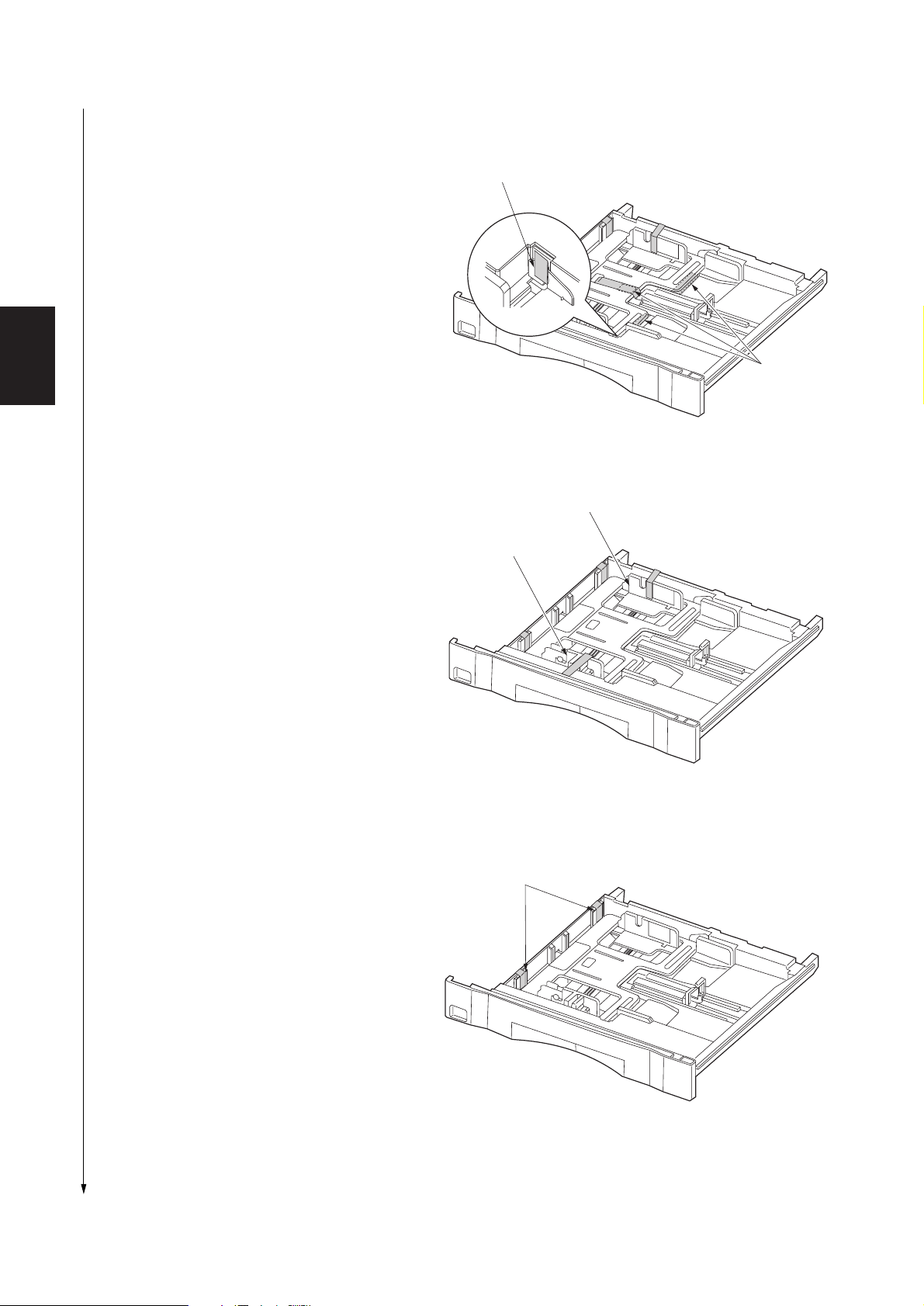
each of the drawer spacers and then the spacers.
8. Remove the tape holding the fulcrum of the
drawer lift inside the drawer.
Fulcrum of the drawer lift
1-3
9. Remove the tape holding each of the front and
rear cursors.
Drawer spacers
Figure 1-3-5
Rear cursor
Front cursor
Figure 1-3-6
10. Remove the tape holding each of the drawer claw
spacers and then the spacers.
11. Refit the drawer.
1-3-6
Drawer claw spacers
Figure 1-3-7
Page 30
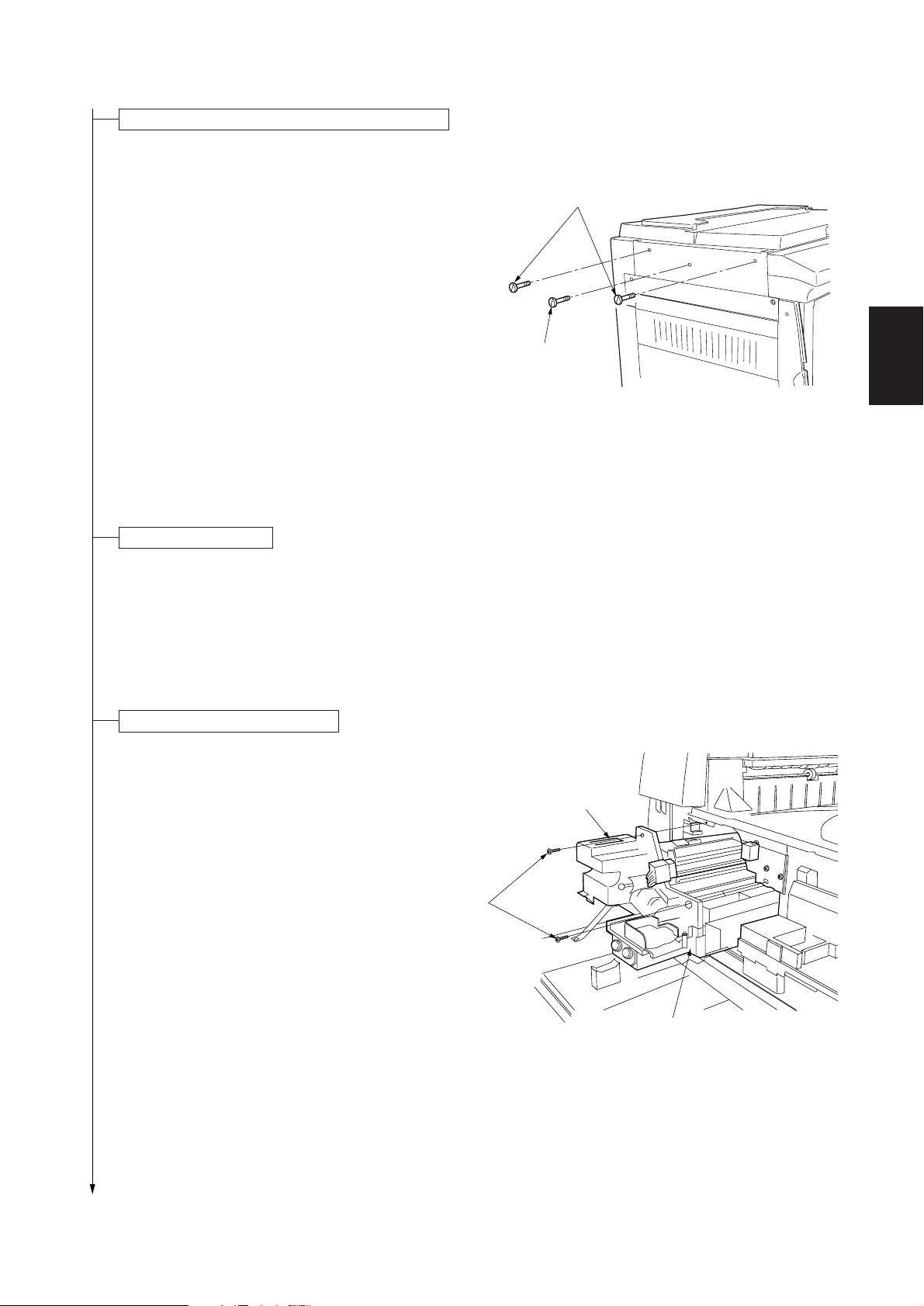
Remove the pins holding light source units 1 and 2.
1. Remove the two pins for light source unit 1 and
the pin for light source unit 2.
2AV/X
Light source unit 1 pins
Install optional devices.
1
1. Install the optional devices (STDF, SRDF*
drawer/s, job separator, duplex unit*1, finisher*
,
1
and/or original cover*2) as necessary (see the
respective installation manuals or service
manuals).
*1: Optional for 20 cpm copier only.
*2: Standard for Asia and Oceania specifications
of the 15 cpm copier.
Remove the image formation unit.
1. Open the front cover, bypass tray and the paper
conveying unit.
2. Remove the two screws. While pressing the hook
on the front image formation cover, pull the image
formation unit out.
Light source unit 2 pin
Hook
1-3
Figure 1-3-8
Screws
Image formation unit
Figure 1-3-9
1-3-7
Page 31

1-3
2AV/X
Load developer.
1. Remove the developing unit upper cover by
pushing and lifting it in the direction of the arrow
in the diagram.
Caution: Be sure to place the image formation
unit on a level surface when loading developer.
2. Shake the developer bottle well to agitate the
developer.
3. While turning the magnet roller gear in the
direction of the arrow in the diagram, uniformly
pour developer into the image formation unit.
Caution: Never turn the magnet roller gear in the
reverse direction.
Developing unit
upper cover
Figure 1-3-10
4. Refit the developing unit upper cover.
Release the cleaning blade.
1. Remove the tape holding each of the two
cleaning blade release levers. Apply the cleaning
blade to the drum by gently pushing the cleaning
blade release levers in the direction of the arrows
in the diagram using a screwdriver.
•The cleaning blade comes into contact with the
drum.
Developer
Cleaning blade
release lever
Magnet roller gear
Figure 1-3-11
Tapes
Screwdriver
1-3-8
Figure 1-3-12
Page 32

2AV/X
2. Check that the cleaning shaft is inserted as far as
it will go.
3. Refit the image formation unit using the two
screws.
4. Connect the 12-pin connector.
Install a waste toner tank.
1.While holding the waste toner tank release lever
up, fit the waste toner tank in the copier.
12-pin connector
1-3
Figure 1-3-13
Waste toner tank
release lever
2. Close the front cover.
Adjust the fixing pressure.
1. Remove the two blue screws.
2. Close the paper conveying unit and the bypass
tray.
Waste toner tank
Figure 1-3-14
Blue screws
Figure 1-3-15
1-3-9
Page 33

1-3
2AV/X
Connect the power cord.
1. Connect the power cord to the connector on the copier.
2. Insert the power plug into the wall outlet.
Carry out initial developer setting (maintenance item U130).
1. Turn the main switch on and enter the maintenance mode by entering “10871087” using the numeric keys.
2. Enter “130” using the numeric keys and press the start key.
3. Press the start key to execute the maintenance item.
The drive stops within approximately 4 minutes and the toner feed start level and toner sensor control voltage are
automatically set.
• On the 20 cpm copier, the settings are displayed on the message display.
Display example
INPUT: 135 (Toner sensor output value)
CONTROL: 181 (Toner sensor control voltage)
TARGET: 138 (Toner feed start level)
HUMID: 57 (Absolute humidity)
• On the 15 cpm copier, each time the copy exposure adjustment keys are pressed, the settings for INPUT,
CONTROL, TARGET and HUMID are displayed on the copy quantity/magnification display in the order presented.
4. Press the stop/clear key.
Load paper.
1. Load paper in the drawer.
Caution: Loading paper before turning the main switch on may cause paper jams.
Output an own-status report (maintenance item U000).
1. Enter “000” using the numeric keys and press the start key.
2. Select “MAINTENANCE” and press the start key to output a list of the current settings of the maintenance items
(20 cpm copier).
Select “d-L” and press the start key to output a list of the current settings of the maintenance items (15 cpm
copier).
3. Press the stop/clear key.
Exit maintenance mode.
1. Enter "001" using the numeric keys and press the start key.
The machine exits the maintenance mode.
1-3-10
Page 34

Install a toner cartridge.
1. Open the front cover.
2. Shift the toner cartridge release lever to the right
until it stops.
3. Tap the toner cartridge on the top five or six times
and shake it horizontally eight to ten times to
agitate the toner.
2AV/X
Toner cartridge release lever
1-3
Figure 1-3-16
4. Align the arrows on the top of the toner cartridge
with the cutouts in the eject tray and then insert
the cartridge into the copier.
5. Secure the toner cartridge by shifting the toner
cartridge release lever to the left until it stops.
6. Close the front cover.
Figure 1-3-17
Cutouts
Toner cartridge
Figure 1-3-18
1-3-11
Page 35

1-3
2AV/X
Make test copies.
1. Place an original and make test copies.
Check if the center lines of the bypass tray and
drawer are correct. If not, adjust the center lines.
Completion of machine installation.
1-3-12
Page 36

1-3-2 Setting initial copy modes
Factory settings are as follows:
2AV/X
Maintenance item
No.
U253 Switching between double and single counts Double count Double count
U254 Turning auto start function on/off On On
U255 Setting auto clear time 90 s 90 s
U256 Turning auto preheat/energy saver function on/off On On
U258 Switching copy operation at toner empty Single mode, Single mode,
detection 70 sheets 70 sheets
U260 Changing the copy count timing After ejection After ejection
U343 Switching between duplex/simplex copy mode Simplex copy Simplex copy
(20 cpm copier only)
U342 Setting the ejection restriction On On
U344 Setting preheat/energy saver mode Energy star Energy star
U348 Setting the copy density adjustment range Special area Special area
Contents
Metric Inch
Factory setting
1-3
1-3-13
Page 37

2AV/X
1-3-3 Copier management
In addition to a maintenance function for service, the copier is equipped with a management function which can be operated
by users (mainly by the copier administrator). In this copier management mode, settings such as default settings can be
changed.
(1) Using the copier management mode (15 cpm copier)
• Executing a department management item • Executing a default setting item
1-3
Start
Press both of the copy
exposure adjustment keys
and numeric key * for 3 s.
Select an item using the zoom
+/– keys or numeric keys.
Press the enter key.
Execute the department
management item
(page 1-3-15).
Select “d00” and
press the enter key.
Start
Press both of the copy exposure adjustment keys for 3 s.
Select an item using the zoom
+/– keys or numeric keys.
Press the enter key.
Execute the default
setting item (page 1-3-15).
Select “F00” and
press the enter key.
1-3-14
End
Page 38

(2) Setting department management items
2AV/X
Turning department management on/off
1. Select “d01” and press the enter key.
2. Select “copy management on” or “copy
management off” and press the enter key.
Setting range: 1 (copy management on)/
2 (copy management off)
Registering a new department code
1. Select “d02” and press the enter key.
2. Enter a department code* using the numeric
keys and press the enter key.
* 4 digits for metric specifications and 7 digits
for inch specifications.
Deleting a department code
1. Select “d03” and press the enter key.
2. Enter the department code to be deleted using
the numeric keys and press the enter key.
(3) Copy default
User status report
Prints the details of the default settings.
1. Select “F01” and press the enter key.
If A4/11" × 8
automatically printed out. Otherwise, select
the paper source and press the start key.
1
/2" paper is present, the list is
Clearing copy counts
1. Select “d04” and press the enter key.
2. Select “clear” or “do not clear” and press the
enter key.
Setting range: 1 (clear)/2 (do not clear)
Printing management list
1. Select “d05” and press the enter key.
If A4/11" × 8
automatically printed out. Otherwise, select
the paper source and press the start key.
Printer department management setting
Note: This setting item will only be displayed when
the optional printer board is installed and the
department management is turned on.
Text original exposure adjustment
Adjusts the exposure to be used when text original
is selected for the image mode.
1. Select “F06” and press the enter key.
2. Select the setting and press the enter key.
Setting range: 1 to 7
1
/2" paper is present, the list is
1-3
Exposure mode
Selects the image mode at power-on.
1. Select “F02” and press the enter key.
2. Select the exposure mode and press the enter
key.
Exposure mode: 1 (auto exposure)/
2 (text & photo)/3 (photo)/4 (text)
Exposure steps
Sets the number of exposure steps for the manual
exposure mode.
1. Select “F03” and press the enter key.
2. Select “5 steps” or “9 steps” and press the
enter key.
Setting range: 1 (5 steps)/2 (9 steps)
Auto exposure adjustment
Adjusts the exposure for the auto exposure mode.
1. Select “F04” and press the enter key.
2. Select the setting and press the enter key.
Setting range: 1 to 7
Text and photo original exposure adjustment
Adjusts the exposure to be used when text and
photo original is selected for the image mode.
1. Select “F05” and press the enter key.
2. Select the setting and press the enter key.
Setting range: 1 to 7
Photo original exposure adjustment
Adjusts the exposure to be used when photo
original is selected for the image mode.
1. Select “F07” and press the enter key.
2. Select the setting and press the enter key.
Setting range: 1 to 7
Paper selection
Sets whether the same sized paper as the original
to be copied is automatically selected.
1. Select “F08” and press the enter key.
2. Select “auto” or “manual” and press the enter
key.
Setting range: 1 (auto)/2 (manual)
AMS mode
Selects whether auto magnification selection or
100% magnification is to be given priority when the
sizes of the original and copy paper are different.
1. Select “F09” and press the enter key.
2. Select “auto magnification selection” or “same
size” and press the enter key.
Setting range: 1 (auto magnification selection)/
2 (same size)
1-3-15
Page 39

2AV/X
1-3
Default drawer
Sets the drawer to be selected in cases such as
after the reset key is pressed.
1. Select “F10” and press the enter key.
2. Select the default drawer and press the enter
key.
Default drawer: 1 (drawer 1)/2 (drawer 2)/
3 (drawer 3)/4 (drawer 4)
Note: This setting item will not be displayed if
no optional drawer is installed.
Automatic drawer switching
Sets whether the automatic drawer switching
function is available.
1. Select “F11” and press the enter key.
2. Select “on” or “off” and press the enter key.
Setting range: 1 (on)/2 (off)
Note: This setting item will not be displayed if
no optional drawer is installed.
Bypass tray paper size
Sets the paper size for the bypass tray so that it will
be automatically selected.
1. Select “F12” and press the enter key.
2. Select the paper size for the bypass tray and
press the enter key.
Paper size: 1 (A3/11" × 17")/2 (A4 vertical/
1
/2" × 14")/3 (A4/81/2" × 11")/
8
1
4 (B4/5
/2" × 81/2")/5 (B5 vertical/11" × 81/2")/
6 (B5/no size setting*)/7 (folio/—)/
8 (no size setting*/—)
* Setting of non-standard size paper width for
bypass tray
Non-standard size paper width setting for bypass tray
Sets the paper width for the bypass tray to use
non-standard size paper.
1. Select “F13” and press the enter key.
2. Enter the setting and press the enter key.
Setting range: 100 to 297 mm
Output form
Selects whether or not to perform sort copying
automatically when the DF is used.
1. Select “F14” and press the enter key.
2. Select “sort on” or “sort off” and press the enter
key.
Setting range: 1 (sort on)/2 (sort off)
Note: This setting item will not be displayed if
the optional memory board is not installed.
Rotate sort
Sets whether or not to perform rotate sorting when
the sort mode is selected.
1. Select “F15” and press the enter key.
2. Select “on” or “off” and press the enter key.
Setting range: 1 (on)/2 (off)
Note: This setting item will not be displayed if
the optional memory board is not installed.
Copy limit
Sets the number of copies limit for multiple copying.
1. Select “F16” and press the enter key.
2. Enter the setting and press the enter key.
Setting range: 1 to 250 copies
Margin width
Sets the default setting of the margin width for the
margin copying.
1. Select “F17” and press the enter key.
2. Enter the setting and press the enter key.
Setting range: Metric
1 to 18 mm
Inch
1
3
1 (
/4")/2 (
")/3 (1/2")/4 (5/8")/5 (3/4")
/8
Note: This setting item will not be displayed if
the optional memory board is not installed.
Border erase width
Sets the default setting of the border erase width
for the border erase mode.
1. Select “F18” and press the enter key.
2. Select the setting and press the enter key.
1
Setting range: 1 (6 mm/
3 (18 mm/
3
/4")
/4")/2 (12 mm/1/2")/
Note: This setting item will not be displayed if
the optional memory board is not installed.
Layout (4 in 1)
Sets whether to place the originals vertically or
horizontally for 4 in 1 layout copying.
1. Select “F19” and press the enter key.
2. Select “vertical (Z)” or “horizontal (N)” and
press the enter key.
Setting range: 1 (vertical [Z])/2 (horizontal [N])
Note: This setting item will not be displayed if
the optional memory board is not installed.
Layout (borderline)
Selects the type of borderline for layout copying.
1. Select “F20” and press the enter key.
2. Select the setting and press the enter key.
Setting range: 1 (none)/2 (solid line)/3 (dotted
line)
Note: This setting item will not be displayed if
the optional memory board is not installed.
Transparency mode
Selects the paper type for copying onto transparencies or thick paper using the bypass tray.
1. Select “F21” and press the enter key.
2. Select “transparencies” or “thick paper” and
press the enter key.
Setting range: 1 (transparencies)/
2 (thick paper)
1-3-16
Page 40

2AV/X
Silent mode
Selects whether or not to enter silent mode after
copying.
1. Select “F22” and press the enter key.
2. Select “on” or “off” and press the enter key.
Setting range: 1 (on)/2 (off)
Copy eject location setting
Selects whether to eject copies to the internal eject
tray or job separator.
1. Select “F23” and press the enter key.
2. Select the copy eject location and press the
enter key.
Setting range: 1 (internal eject tray)/
2 (job separator)
Note: This setting item will not be displayed if
the optional job separator is not installed.
Auto shutoff
Sets whether the auto shutoff function is available.
1. Select “F24” and press the enter key.
2. Select “on” or “off” and press the enter key.
Setting range: 1 (on)/2 (off)
Auto preheat time
Sets the auto preheat time.
1. Select “F25” and press the enter key.
2. Select the setting and press the enter key.
Setting range: 5 to 45 minutes (in 5-minute
increments)
1 (5 min)/2 (10 min)/3 (15 min)/4 (20 min)/
5 (25 min)/6 (30 min)/7 (35 min)/8 (40 min)/
9 45 min)
Note: Set the auto preheat time to be shorter
than the auto shutoff time.
Auto shutoff time
Sets the auto shutoff time.
1. Select “F26” and press the enter key.
2. Select the setting and press the enter key.
Setting range: 15 to 240 minutes (in 15-minute
increments)
1 (15 min)/2 (30 min)/3 (45 min)/4 (60 min)/
5 (75 min)/6 (90 min)/7 (105 min)/8 (120 min)/
9 (135 min)/10 (150 min)/11 (165 min)/
12 (180 min)/13 (195 min)/14 (210 min)/
15 (225 min)/16 (240 min)
Toner counter report
Prints the report on the toner consumption ratio.
1. Select “F27” and press the enter key.
If A4/11" × 8
automatically printed out. Otherwise, select
the paper source and press the start key.
1
/2" paper is present, the list is
1-3
1-3-17
Page 41

2AV/X
(4) Using the copier management mode (20 cpm copier)
Start
Press
the */language key.
Select “Management” and
press the enter key.
1-3
Enter the
management code.
Select “Copy default” and
press the enter key.
Enter the
management code.
Select “Machine default” and
press the enter key.
Enter the
management code.
Select “Language” and
press the enter key.
Execute department management items (page 1-3-19).
Select “End” and
press the enter key.
Make copy default settings
(page 1-3-19).
Select “End” and
press the enter key.
Make machine default settings
(page 1-3-20).
Select “End” and
press the enter key.
Set the language (page 1-3-21).
1-3-18
End
Page 42

(5) Setting department management items
2AV/X
Registering a new department code
Sets a department code and the limit of the
number of copies for that department.
1. Select “Management Setting” (“COPY MGMT
SETTING”) and press the enter key.
2. Select “Register” and press the enter key.
3. Enter a department code* using the numeric
keys and press the enter key.
* 4 digits for metric specifications and 7 digits
for inch specifications.
4. Select “Copy limit”. Enter the number of copies
limit using the numeric keys and press the
enter key.
Deleting a department code
1. Select “Management Setting” (“COPY MGMT
SETTING”) and press the enter key.
2. Select “Code delete” and press the enter key.
3. Select the department code to be deleted and
press the enter key.
4. Select “Yes” or “No” and press the enter key.
Altering the copy limit
1. Select “Management Setting” (“COPY MGMT
SETTING”) and press the enter key.
2. Select “Copy limit correction” and press the
enter key.
3. Select the department code to be altered and
press the enter key.
4. Enter the new number of copies limit using the
numeric keys.
Clearing copy counts
1. Select “Management Setting” (“COPY MGMT
SETTING”) and press the enter key.
2. Select “Count delete” (“COUNTS CLEAR”)
and press the enter key.
3. Select “Yes” or “No” and press the enter key.
Viewing copy counts
1. Select “Reference” and press the enter key.
2. Select “All Department total” (“TOTAL: ALL IDCODES”) and press the enter key.
3. View copy counts using the cursor up/down
keys.
Print management list
1. Select “Printer management list” (“PRINT
MANAGEMENT LIST”) and press the enter
key.
If A4/11" × 81/2" paper is present, the list is
automatically printed out. Otherwise, select
the paper source and press the start key.
Turning department management on/off
1. Select “Management on/off” (“COPY MANAGEMENT ON/OFF”) and press the enter key.
2. Select “On” or “Off” and press the enter key.
Turning printer department management on/off
Note: This setting item will not be displayed if the
optional printer board is not installed.
1-3
(6) Copy default
Exposure mode
Selects the image mode at power-on.
1. Select “Exposure mode” and press the enter
key.
2. Select the exposure mode and press the enter
key.
Exposure mode: Auto mode/Mixed mode/Photo
mode/Text mode
Exposure steps
Sets the number of exposure steps for the manual
exposure mode.
1. Select “Exposure steps” and press the enter
key.
2. Select “5 steps” or “9 steps” and press the
enter key.
Turning printer error report function on/off
Note: This setting item will not be displayed if the
optional printer board is not installed.
Auto exposure adjustment
Adjusts the exposure for the auto exposure mode.
1. Select “Auto exposure adjustment” (“AUTO
EXP. LEVEL ADJUST”) and press the enter
key.
2. Select the setting and press the enter key.
Setting range: 1 to 7
Mixed original density
Adjusts the exposure to be used when text and
photo original is selected for the image mode.
1. Select “Mixed original density set” and press
the enter key.
2. Select the setting and press the enter key.
Setting range: 1 to 7
1-3-19
Page 43

2AV/X
1-3
Photo original density
Adjusts the exposure to be used when photo
original is selected for the image mode.
1. Select “Photo original density set” and press
the enter key.
2. Select the setting and press the enter key.
Setting range: 1 to 7
Text original exposure adjustment
Adjusts the exposure to be used when text original
is selected for the image mode.
1. Select “Text original density set” and press the
enter key.
2. Select the setting and press the enter key.
Setting range: 1 to 7
Paper selection
Sets whether the same sized paper as the original
to be copied is automatically selected.
1. Select “Paper selection” and press the enter key.
2. Select “Auto” or “Manual” and press the enter
key.
AMS mode
Selects whether auto magnification selection or
100% magnification is to be given priority when the
sizes of the original and copy paper are different.
1. Select “AMS mode” and press the enter key.
2. Select “AMS” or “100%” and press the enter key.
Copy limit
Sets the number of copies limit for multiple copying.
1. Select “Copy limit” and press the enter key.
2. Enter the setting and press the enter key.
Setting range: 1 to 250 copies
Margin width
Sets the default setting of the margin width for the
margin copying.
1. Select “Margin width” and press the enter key.
2. Enter the setting and press the enter key.
Setting range: Metric
1 to 18 mm
Inch
1
/4" to 3/4" (in 1/8" increments)
Border erase width
Sets the default setting of the border erase width
for the border erase mode.
1. Select “Border Erase Width” and press the
enter key.
2. Select the setting and press the enter key.
Setting range: Metric
6/12/18 mm
Inch
1
/4"/1/2"/3/4"
Default drawer
Sets the drawer to be selected in cases such as
after the reset key is pressed.
1. Select “Default drawer” and press the enter
key.
2. Select the default drawer and press the enter
key.
Default drawer: 1st pap. (SOURCE 1)/2nd
pap. (SOURCE 2)/3rd pap. (SOURCE 3)/4th
pap. (SOURCE 4)
Note: 3rd pap. (SOURCE 3) and 4th pap.
(SOURCE 4) are displayed only when the
optional drawer is installed.
Output form
Selects whether or not to perform sort copying
automatically when the DF is used.
1. Select “Output form” and press the enter key.
2. Select “Sort: ON” or “Sort: OFF” and press the
enter key.
Note: If the DF is not installed, this setting item
will be displayed but ineffective.
Rotate sort
Sets whether or not to perform rotate sort copying
when the sort mode is selected.
1. Select “Rotate sort” and press the enter key.
2. Select “On” or “Off” and press the enter key.
Note: This setting item will not be displayed if
the optional finisher is installed.
(7) Machine default
Status report
Prints the details of the default settings.
1. Select “Status report” and press the enter key.
1
If A4/11" × 8
/2" paper is present, the list is
automatically printed out. Otherwise, select
the paper source and press the start key.
Auto shutoff
Sets whether the auto shutoff function is available.
1. Select “Auto shut-off” and press the enter key.
2. Select “On” or “Off” and press the enter key.
1-3-20
Special paper
If special paper such as colored paper and
recycled paper is loaded, a sign (*) indicating
special paper can be shown beside the paper size
for the drawer that contains special paper.
1. Select “Special paper” and press the enter key.
2. Select the paper source and press the enter key.
Paper source: 1st pap. (SOURCE 1)/2nd pap.
(SOURCE 2)/3rd pap. (SOURCE 3)/4th pap.
(SOURCE 4)
Note: 3rd pap. (SOURCE 3) and 4th pap.
(SOURCE 4) are displayed only when the
optional drawer is installed.
Page 44

2AV/X
APS for special paper
Sets whether to use the paper source with the
special paper for auto paper selection and auto
drawer switching.
1. Select “APS for special paper” and press the
enter key.
2. Select “On” or “Off” and press the enter key.
Paper type (1st to 4th)
Selects the type of paper to be loaded in the
drawers.
1. Select “Paper type (1st to 4th)” and press the
enter key.
2. Select the paper type and press the enter key.
Paper type: Plain/Recycled/Letterhead/Color
Note: “3rd” and “4th” are displayed only when
the optional drawer is installed.
Paper type (bypass)
Selects the type of paper to be loaded in the
bypass tray.
1. Select “Paper type (bypass)” and press the
enter key.
2. Select the paper type and press the enter key.
Paper type: Plain/Transparency/Labels/Recycled/Rough/Letterhead/Color/Envelope/Cardstock
Copy eject location setting
Selects whether to eject copies to the internal eject
tray, finisher or job separator.
1. Select “Select copy eject mode” (“SELECT
EJECTOR OF COPY”) and press the enter
key.
2. Select the eject location and press the enter
key.
Copy eject location: Copier/Finisher/Job separator
Note: This setting item will not be displayed if
neither the optional finisher nor job separator
is installed.
Auto preheat time
Sets the auto preheat time.
1. Select “Auto preheat time” and press the enter
key.
2. Select the setting and press the enter key.
Setting range: 5 to 45 minutes (in 5-minute
increments)
Note: Set the auto preheat time to be shorter
than the auto shutoff time.
Auto shutoff time
Sets the auto shutoff time.
1. Select “Auto shut-off time” and press the enter
key.
2. Select the setting and press the enter key.
Setting range: 15 to 240 minutes (in 15-minute
increments)
Display contrast adjustment
Adjusts the contrast of the LCD.
1. Select “Display contrast adjustment” (“DISPLAY CONTRAST ADJUST.”) and press the
enter key.
2. Enter the setting and press the enter key.
Setting range: 1 to 7
Management code change
Changes the management code.
1. Select “Management code change” and press
the enter key.
2. Enter the 4-digit management code using the
numeric keys and press the enter key.
Silent mode
Selects whether or not to enter silent mode after
copying.
1. Select “Silent Mode” and press the enter key.
2. Select “On” or “Off” and press the enter key.
Auto drawer switching
Sets whether the auto drawer switching function is
available.
1. Select “Automatic drawer switching” and press
the enter key.
2. Select “On” or “Off” and press the enter key.
Counter report
Prints the report on the toner consumption ratio.
1. Select “Counter report” and press the enter
key.
If A4/11" × 8
automatically printed out. Otherwise, select
the paper source and press the start key.
1
/2" paper is present, the list is
1-3
(8) Language
Switches the language to be displayed on the
touch screen.
1. Select “Language” and press the enter key.
2. Select the display language and press the
enter key.
1-3-21
Page 45

1-3
2AV/X
1-3-4 Installing the key counter (option)
Key counter installation requires the following parts:
Key counter set (P/N 2A369702)
Contents of the set:
• Key counter cover (P/N 2A360010)
• Key counter retainer (P/N 66060030)
• Key counter cover retainer (P/N 66060022)
• Key counter mount (P/N 66060040)
• Key counter socket assembly (P/N 41529210)
• One (1) M3 × 8 bronze binding screw (P/N B1303080)
• Four (4) M4 × 6 bronze TP-A screws (P/N B4304060)
• Two (2) M4 × 10 bronze TP-A screws (P/N B4304100)
• One (1) M4 × 20 bronze TP-A screws (P/N B4304200)
• One (1) M4 × 6 chrome TP-A screw (P/N B4104060)
• Two (2) M3 × 6 bronze flat-head screws (P/N B2303060)
• One (1) M3 bronze nut (P/N C2303000)
Procedure
1. Fit the key counter socket assembly to the key
counter retainer using the two screws and nut.
2. Fit the key counter mount to the key counter
cover using the two screws, and attach the key
counter retainer to the mount using the two
screws.
M4 × 6 screws
(B4304060)
M3 nut
(C2303000)
Key counter retainer (66060030)
Key counter mount (66060040)
Key counter cover
(2A360010)
3. Open the front cover.
4. Remove the screw on the front of the internal
eject tray.
5. Remove the five screws. While lifting the
internal eject tray, remove the right cover.
6. Cut out the aperture plate on the right cover
using a pair of nippers.
7. Pass the 4-pin connector inside the copier
through the aperture.
M4 × 6 screws
(B4304060)
Key counter socket
assembly (41529210)
M3 × 6 flat-head screws (B2303060)
Figure 1-3-19
Screw
Front cover
Internal eject tray
Aperture
plate
Screws
Right cover
Screws
4-pin connector
1-3-22
Figure 1-3-20
Page 46

8. Refit the right cover.
9. Pass the 4-pin connector of the key counter
through the aperture in the key counter cover
retainer, and insert into the 4-pin connector of
the copier.
10. Seat the projection of the key counter cover
retainer in the aperture in the right cover, and
fasten them both to the copier using three
screws.
11. Fit the key counter cover with the key counter
socket assembly inserted to the key counter
cover retainer on the copier using the screw.
12. Insert the key counter into the key counter
socket assembly.
13. Turn the main switch on and enter the maintenance mode.
14. Run maintenance item U204 and set as
follows:
15 cpm: C-2
20 cpm: Key counter
15. Exit the maintenance mode.
16. Check that the indication given below is
displayed on the operation panel when the key
counter is pulled out.
15 cpm: U1
20 cpm: Insert key counter.
17. Check that the counter counts up as copies
are made.
4-pin connector
4-pin connector
Key counter cover retainer
(66060022)
M4 × 10 screw
(B4304100)
M4 × 20 screw
(B4304200)
Figure 1-3-21
2AV/X
M3 × 8 screw
(B1303080)
Key counter cover
1-3
M4 × 6 screw
(B4104060)
1-3-23
Page 47

1-3
2AV/X
1-3-5 Installing the original size detection sensor (option for the metric specifications of
the 15 cpm copier only)
Original size detection sensor installation requires the following parts:
• Original size detection sensor (P/N 35927290)
• One (1) M3 × 8 bronze binding screw (P/N B1303080)
Procedure
1. Remove the original cover or the DF.
2. Remove the five screws holding the right
cover. While shifting the right cover in the direction of the arrow in the diagram, remove the
contact glass.
Contact glass
Right cover
3. Remove the eight screws holding the ISU
cover and then the cover.
4. Fit the original size detection sensor using the
screw.
5. Connect the 3-pin connector that was contain-
ed inside the ISU cover to the original size
detection sensor.
6. Refit all the removed parts.
7. Turn the main switch on and enter mainte-
nance mode.
8. Run maintenance item U075 and select “On”.
9. Exit maintenance mode.
10. Check that the automatic original size detection is performed correctly.
ISU cover
Original size
detection sensor
Figure 1-3-22
Figure 1-3-23
M3 × 8 screw (B1303080)
1-3-24
3-pin connector
Figure 1-3-24
Page 48

1-3-6 Installing the drawer heater (option)
Drawer heater installation requires the following parts:
For 120 V specifications
Drawer heater set (P/N 3A569710)
Contents of the set
• One (1) BVM4 × 4 bronze binding screw (P/N B1304040)
• Two (2) BVM4 × 6 bronze binding screws (P/N B1304060)
• Clamp (P/N M2105030)
• Band (P/N M2607010)
• High temperature caution sticker (P/N 20305130)
• Drawer heater wire (P/N 3A568010)
• Drawer heater (P/N 34860030)
2AV/X
For 220-240 V specifications
Drawer heater set (P/N 3A569720)
Contents of the set
• One (1) BVM4 × 4 bronze binding screw (P/N B1304040)
• Two (2) BVM4 × 6 bronze binding screws (P/N B1304060)
• Clamp (P/N M2105030)
• Band (P/N M2607010)
• High temperature caution sticker (P/N 20305130)
• Drawer heater wire (P/N 3A568010)
• Drawer heater (P/N 34860020)
Procedure
1. Remove the two screws holding the rear cover of the
optional drawer and then the cover.
2. Pull the drawer out.
3. Pass the connector of the drawer heater through the
cable hole in the rear base and fit the drawer heater
using the two BVM4 × 06 bronze binding screws.
4. Fasten the drawer heater cable with the clamp using
the BVM4 × 04 bronze binding screw.
5. Affix the high temperature caution sticker.
1-31-3
BVM4 × 4 screw
Clamp
BVM4 × 6 screws
High temperature
caution sticker
6. Fold the cable that was passed through the cable
hole in three and tidy it up using the band.
Figure 1-3-25
Band
Figure 1-3-26
1-3-25
Page 49

2AV/X
7. Insert one of the 2-pin receptacles on the heater wire
into the opening in the frame and connect the other
2-pin receptacle to the drawer heater cable.
2-pin receptacle
1-3
8. Refit the drawer.
9. Install the optional drawer to the copier.
10. Remove the jumper connector from the heater wire
on the copier or the above optional drawer and
connect the 2-pin connector on the heater wire in its
place.
Opening
2-pin
connector
2-pin receptacle
Figure 1-3-27
11. Refit the rear cover of the optional drawer.
1-3-26
Figure 1-3-28
Page 50

1-4-1 Maintenance mode
The copier is equipped with a maintenance function which can be used to maintain and service the machine.
(1) Executing a maintenance item
Start
2AV/X
Enter 10871087.
Enter the number of the maintenance
item to be executed using the cursor
up/down keys (20 cpm), the zoom +/keys (15 cpm) or numeric keys.
Press the start key.
The maintenance item is run.
Press the stop/clear key.
· · · · · · · Entering the maintenance mode
· · · · · · · Selecting a maintenance item
1-4
Yes
Yes
Enter 001 using the cursor up/down keys
(20 cpm), the zoom +/- keys (15 cpm) or
numeric keys, and press the print key.
Run the item again?
No
Run another maintenance
mode?
No
End
· · · · · · · Exiting the maintenance mode
1-4-1
Page 51

1-4
2AV/X
(2) Maintenance mode item list (for 20 cpm copier)
Section
General
Initialization
Drive, paper
feed, paper
conveying and
cooling system
Optical
High voltage
* Initial setting for executing maintenance item U020
Item
No. setting*
U000 Outputting an own-status report
U001 Exiting the maintenance mode
U003 Setting the service telephone number
U004 Setting the machine number
U005 Copying without paper
U019 Displaying the ROM version
U020 Initializing all data
U021 Initializing memories
U022 Initializing backup data
U030 Checking motor operation
U031 Checking switches for paper conveying
U032 Checking clutch operation
U033 Checking solenoid operation
U034 Adjusting the print start timing
Adjusting leading edge registration
Adjusting the center line
U035 Setting folio size
Length
Width
U051 Adjusting the amount of slack in the paper
At the registration roller
At the paper feed roller
U053 Performing fine adjustment of the motor speed
Drive motor/Polygon motor/Feedshift motor
U060 Adjusting the scanner input properties
U061 Turning the exposure lamp on
U063 Adjusting the shading position
U065 Adjusting the scanner magnification
Main scannning direction/auxiliary scanning direction
U066 Adjusting the leading edge registration for scanning an original on the
contact glass
U067 Adjusting the center line for scanning an original on the contact glass
U070 Adjusting the DF magnification
U071 Adjusting the DF scanning timing
Adjusting the DF leading edge registration
Adjusting the DF trailing edge registration
U072 Adjusting the DF center line
U073 Checking scanner operation
U074 Adjusting the DF input light luminosity
U087 Turning the DF scanning position adjust mode on/off
U088 Setting the input filter (moiré reduction mode)
U091 Checking shading
U092 Adjusting the scanner automatically
U093 Setting the exposure density gradient
U099 Checking the original size detection
U100 Setting the surface potential
U101 Setting high voltages
Developing bias control voltage during image formation
Developing bias control voltage during no image formation
Transfer control voltage
Transfer voltage output timing
U109 Setting the drum type
U110 Checking/clearing the drum count
Maintenance item contents
1-4-2
Initial
—
—
***************
0
—
—
—
—
—
—
—
—
—
0
0
330
210
0
0
0
12
—
0
0/0
0
0
0
0
0
0
—
1
On
Off
—
—
0
—
184
193
38
115
–176
H type
—
Page 52

2AV/X
Section
High voltage
Developing
Fixing and
cleaning
Operation panel
and support
equipment
Mode setting
Image
processing
* Initial setting for executing maintenance item U020
Item
No. setting*
U111 Checking/clearing the drum drive time
U130 Initial setting for the developer
U131 Setting the toner sensor control voltage
U132 Replenishing toner forcibly
U135 Checking toner feed motor operation
U155 Displaying the toner sensor output
U156 Changing the toner control level
Toner feed start level
Toner empty level
U157 Checking/clearing the developing drive time
U158 Checking/clearing the developing count
U161 Setting the fixing control temperature
Primary stabilization fixing temperature
Secondary stabilization fixing temperature
Control temperature during copying
Temperature to be deducted from the control temperature when copying
onto paper with a width of 220 mm or smaller
U162 Stabilizing fixing forcibly
U163 Resetting the fixing problem data
U196 Turning the fixing heater on
U199 Checking the fixing temperature
U200 Turning all LEDs on
U203 Operating DF separately
U204 Setting the presence or absence of a key card or key counter
U207 Checking the operation panel keys
U210 Reversing the LCD
U211 Setting DF type
U240 Checking the operation of finisher motors and solenoids
U241 Checking the finisher switches
U243 Checking the operation of the DF motors, solenoids and clutch
U244 Checking the DF switches (when installing the optional SRDF)
Checking the DF switches (when installing the optional STDF)
U245 Checking messages
U250 Setting the maintenance cycle
U251 Checking/clearing the maintenance count
U252 Setting the destination
U253 Switching between double and single counts
U254 Turning auto start function on/off
U255 Setting auto clear time
U256 Turning auto preheat/energy saver function on/off
U258 Switching copy operation at toner empty detection
U260 Changing the copy count timing
U265 Setting the destination specifications
U330 Setting the number of sheets to enter stacking mode during sort operation
U332 Setting the size conversion factor
U342 Setting the ejection restriction
U343 Switching between duplex/simplex copy mode
U344 Setting preheat/energy saver mode
U345 Setting the value for maintenance due indication
U348 Setting the copy density adjustment range
U402 Adjusting margins of image printing
U403 Adjusting margins for scanning an original on the contact glass
Maintenance item contents
Initial
—
—
155
—
—
—
100
44
—
—
135
160
180
0
1-4
—
—
—
—
—
—
Off
—
Off
SRDF
—
—
—
—
—
—
100
—
Japan
Double
On
90
On
Single/70
Eject
0
100
—
On
Off
Energy star
0
Special
—
—
1-4-3
Page 53

2AV/X
1-4
Section
Image
processing
Others
Item
No. setting*
U404 Adjusting margins for scanning an original from the DF
U407 Adjusting the leading edge registration for memory image printing
U901 Checking/clearing copy counts by paper feed locations
U903 Checking/clearing the paper jam counts
U904 Checking/clearing the service call counts
U905 Checking/clearing counts by optional devices
U906 Resetting partial operation control
U908 Changing the total counter value
U910 Clearing the black ratio data
U914 Switching between fax and copier modes
U917 Setting the reading/writing of backup data
U990 Checking/clearing the time for the exposure lamp to light
U992 Checking or clearing the printer/fax count
U993 Outputting a VTC-PG pattern
U998 Outptting the memory list
Maintenance item contents
Initial
—
—
—
—
—
—
—
—
—
Copier mode
Read
—
—
—
—
* Initial setting for executing maintenance item U020
1-4-4
Page 54

(3) Contents of maintenance mode items (for 20 cpm copier)
2AV/X
Maintenance
item No.
U000 Outputting an own-status report
Description
Outputs lists of the current settings of the maintenance items, and paper jam and service call occurrences.
Purpose
To check the current setting of the maintenance items, or paper jam or service call occurrences.
Before initializing or replacing the backup RAM, output a list of the current settings of the maintenance items
to reenter the settings after initialization or replacement.
Method
1. Press the start key. The screen for selecting an item is displayed.
2. Select the item to be output using the cursor up/down keys. The selected item is displayed in reverse.
Display
MAINTENANCE
JAM
SERVICE CALL
3. Press the start key. The interrupt copy mode is entered and a list is output.
When A4/11" × 8
location.
When output is complete, the screen for selecting an item is displayed.
Completion
Press the stop/clear key at the screen for selecting an item. The screen for selecting a maintenance item
No. is displayed.
1
List of the current settings of the maintenance modes
List of the paper jam occurrences
List of the service call occurrences
/2" paper is available, a report of this size is output. If not, specify the paper feed
Description
Output list
1-4
U001 Exiting the maintenance mode
Description
Exits the maintenance mode and returns to the normal copy mode.
Purpose
To exit the maintenance mode.
Method
Press the start key. The normal copy mode is entered.
1-4-5
Page 55

2AV/X
1-4
Maintenance
item No.
U003 Setting the service telephone number
Description
Sets the telephone number to be displayed when a service call code is detected.
Purpose
To set the telephone number to call service when installing the machine.
Method
Press the start key. The currently set telephone number is displayed.
Setting
1. Enter a telephone number (up to 16 digits) using the numeric keys.
Move the cursor using the cursor left/right keys and select a number or symbol using the cursor up/down
keys.
To enter symbols, press the keys shown below as required.
Key
* key
# key
Auto mode selection key
Image mode selection key
Copy exposure adjustment key (lighter)
Copy exposure adjustment key (darker)
2. Press the start key. The phone number is set, and the screen for selecting a maintenance item No. is
displayed.
Completion
To exit this maintenance item without changing the current setting, press the stop/clear key. The screen for
selecting a maintenance item No. is displayed.
Description
Symbol
*
#
(
)
–
(Space)
U004 Setting the machine number
Description
Displays and changes the machine number.
Purpose
To check or set the machine number.
Method
Press the start key. The currently set machine number is displayed.
Setting
1. Enter the last six digits of the machine number using the numeric key.
Do not enter the first two digits, 3 and 7.
2. Press the start key. The machine number is set.
Completion
To exit this maintenance item without changing the current setting, press the stop/clear key. The screen for
selecting a maintenance item No. is displayed.
1-4-6
Page 56

2AV/X
Maintenance
item No.
U005 Copying without paper
Description
Simulates the copy operation without paper feed.
Purpose
To check the overall operation of the machine.
Method
1. Press the start key. The screen for selecting an item is displayed.
2. Select the item to be operated using the cursor up/down keys. The selected item is displayed in reverse.
Display
PPC
PPC + DF
3. Press the interrupt key. The copy mode screen is displayed.
4. Set the operation conditions required on the copy mode screen. Changes in the following settings can be
made.
• Paper feed locations
• Magnifications
• Simplex or duplex copy mode
• Number of copies: continuous copying is performed when set to 250.
• Copy density
• Keys on the operation panel other than the energy saver (preheat) key
5. To control the paper feed pulley, remove all the paper in the drawers, or the drawers. With the paper
present, the paper feed pulley does not operate.
6. Press the start key. The operation starts.
Copy operation is simulated without paper under the set conditions. When operation is complete, the
screen for selecting an item is displayed.
7. To stop continuous operation, press the stop/clear key.
Completion
Press the stop/clear key at the screen for selecting an item. The screen for selecting a maintenance item
No. is displayed.
Description
Operation
Only the copier operates.
Both the copier and SRDF operate (continuous operation).
1-4
U019 Displaying the ROM version
Description
Displays the part number of the ROM fitted to each PCB.
Purpose
To check the part number or to decide if the ROM version is new from the last digit of the number.
Method
Press the start key. The last six digits of the part number indicating the ROM version are displayed.
Display
MAIN
MMI
Completion
Press the stop/clear key. The screen for selecting a maintenance item No. is displayed.
Main ROM IC
Operation 1 ROM IC
Description
1-4-7
Page 57

2AV/X
1-4
Maintenance
item No.
U020 Initializing all data
Description
Initializes all the backup RAM on the main PCB to return to the original settings.
Purpose
Used when replacing the backup RAM on the main PCB.
Method
1. Press the start key. The screen for executing is displayed.
2. Select EXECUTE using the cursor up/down keys. It is displayed in reverse.
3. Press the start key. All data in the backup RAM is initialized, and the original settings for Japan
specifications are set.
When initialization is complete, the machine automatically returns to the same status as when the main
switch is turned on and the display language to the initial setting of English.
Completion
To exit this maintenance item without executing initialization, press the stop/clear key. The screen for
selecting a maintenance item No. is displayed.
U021 Initializing memories
Description
Initializes the setting data other than that for adjustments due to variations between respective machines,
i.e., settings for counters, service call history and mode settings. As a result, initializes the backup RAM
according to the specifications depending on the destination selected in U252.
Purpose
Used to return the machine settings to the factory settings.
Method
1. Press the start key. The screen for executing is displayed.
2. Select EXECUTE using the cursor up/down keys. It is displayed in reverse.
3. Press the start key. All data other than that for adjustments due to variations between machines is
initialized based on the destination setting.
Completion
Press the stop/clear key. The screen for selecting a maintenance item No. is displayed.
Description
U022 Initializing backup data
Description
Initializes only the data set for the optical section.
Purpose
To be executed after replacing the scanner unit.
Method
1. Press the start key. The screen for executing is displayed.
2. Select SCANNER using the cursor up/down keys.
3. Press the start key.
4. Select EXECUTE using the cursor up/down keys. It is displayed in reverse.
5. Press the start key. The data for the optical section (U060 to 099, U403, U404 and U990) is initialized.
Completion
Press the stop/clear key. The screen for selecting a maintenance item No. is displayed.
1-4-8
Page 58

2AV/X
Maintenance
item No.
U030 Checking motor operation
Description
Drives each motor.
Purpose
To check the operation of each motor.
Method
1. Press the start key. The screen for selecting an item is displayed.
2. Select the motor to be operated using the cursor up/down keys.
3. Press the start key. The selected item is displayed in reverse and the operation starts.
Display
MAIN
Tumiki1
Tumiki2
Tumiki3
DUP (F, L)
DUP (F, H)
DUP (R, L)
DUP (R, H)
* Optional.
4. To stop operation, press the stop/clear key.
Completion
Press the stop key after operation stops. The screen for selecting a maintenance item No. is displayed.
Drive motor turns on and developing bias turns on
Drawer drive motor turns on
Drawer drive motor (ST) 1* turns on
Drawer drive motor (ST) 2* turns on
Feedshift motor* rotates forward at low speed
Feedshift motor* rotates forward at high speed
Feedshift motor* rotates in reverse at low speed
Feedshift motor* rotates in reverse at high speed
Description
Operation
1-4
U031 Checking switches for paper conveying
Description
Displays the on-off status of each paper detection switch on the paper path.
Purpose
To check if the switches for paper conveying operate correctly.
Method
1. Press the start key. A list of the switches, the on-off status of which can be checked, are displayed.
2. Turn each switch on and off manually to check the status.
When the on-status of a switch is detected, that switch is displayed in reverse.
Display
T2
T3
T4
RES
EJE
DUP1
DUP2
JOB
DUP SF
*Optional.
Completion
Press the stop/clear key. The screen for selecting a maintenance item No. is displayed.
Drawer feed switch (DFSW)
Drawer feed switch (ST) 1* (DFSW (ST) 1)
Drawer feed switch (ST) 2* (DFSW (ST) 2)
Registration switch (RSW)
Eject switch (ESW)
Duplex paper conveying switch 1* (DUPPCSW1)
Duplex paper conveying switch 2* (DUPPCSW2)
Job separator eject switch* (JBESW)
Duplex open/close switch* (DUPOCSW)
Switches
1-4-9
Page 59

2AV/X
1-4
Maintenance
item No.
U032 Checking clutch operation
Description
Turns each clutch on.
Purpose
To check the operation of each clutch.
Method
1. Press the start key. The screen for selecting an item is displayed.
2. Select the clutch to be operated using the cursor up/down keys.
3. Press the start key. The selected item is displayed in reverse, and the clutch turns on for 1 s.
Display
PFHON
PFBYP
T1
T2
T3
RES
*Optional.
Completion
Press the stop/clear key. The screen for selecting a maintenance item No. is displayed.
Description
Clutches
Upper paper feed clutch (PFCL-U)
Bypass paper feed clutch (BYPPFCL)
Lower paper feed clutch (PFCL-L)
Paper feed clutch (ST) 1* (PFCL (ST) 1)
Paper feed clutch (ST) 2* (PFCL (ST) 2)
Registration clutch (RCL)
U033 Checking solenoid operation
Description
Turns each solenoid on.
Purpose
To check the operation of each solenoid.
Method
1. Press the start key. The screen for selecting an item is displayed.
2. Select the solenoid to be operated using the cursor up/down keys.
3. Press the start key. The selected item is displayed in reverse, and the solenoid turns on for 1 s.
Display
BRA_ACT
BRA_RET
MAIN SW
DUP_ACT
DUP_RET
DUP_ACT2
DUP_RET2
Feedshift solenoid (FSSOL)*
Feedshift solenoid (FSSOL)*
Main switch turns off
Feedshift solenoid (FSSOL)*
Feedshift solenoid (FSSOL)*
Duplex feedshift solenoid (DUPFSSOL)*
Duplex feedshift solenoid (DUPFSSOL)*
*1: Optional finisher.
*2: Optional duplex unit.
Completion
Press the stop/clear key. The screen for selecting a maintenance item No. is displayed.
Solenoids
1
latch-on
1
release
2
latch-on
2
release
2
latch-on
2
release
U034 Adjusting the print start timing
Adjustment
See pages 1-6-10 and 13.
1-4-10
Page 60

2AV/X
Maintenance
item No.
U035 Setting folio size
Description
Changes the image area for copying onto folio size paper.
Purpose
To prevent the image at the trailing edge, or right or left side of the paper from not being copied by setting
the actual size of the folio paper used.
Method
Press the start key. The screen for selecting an item is displayed.
Setting
1. Select the item to be set using the cursor up/down keys. The selected item is displayed in reverse.
2. Change the setting using the cursor left/right keys.
Display
LENGTH DATA
WIDTH DATA
3. Press the start key. The value is set.
Completion
Press the stop/clear key. The screen for selecting a maintenance item No. is displayed.
U051 Adjusting the amount of slack in the paper
Adjustment
See page 1-6-17.
Setting
Length
Width
Setting range Initial setting
330 to 356 mm
200 to 220 mm
Description
330
210
1-4
U053 Performing fine adjustment of the motor speed
Description
Performs fine adjustment of the speeds of the motors.
Purpose
Used to adjust the speed of the respective motors when the magnification is not correct.
Method
Press the start key. The screen for selecting an item is displayed.
Setting
1. Select the item to be set using the cursor up/down keys. The selected item is displayed in reverse.
2. Change the setting using the cursor left/right keys.
Display
MAIN MOTOR
POLYGON
MOTOR
DUP MOTOR
* Optional.
MAIN MOTOR
Increasing the setting makes the image longer in the auxiliary scanning direction, and decreasing it
makes the image shorter in the auxiliary scanning direction.
POLYGON MOTOR
Increasing the setting makes the image longer in the main scanning direction and shorter in the auxiliary
scanning direction; decreasing the setting makes the image shorter in the main scanning direction and
longer in the auxiliary scanning direction.
3. Press the start key. The value is set.
Description
Drive motor speed adjustment
Polygon motor speed
adjustment
Feedshift motor* speed
adjustment
Setting range Initial setting
–5 to +5
–5 to +5
–5 to +5
0
0
0
1-4-11
Page 61

2AV/X
1-4
Maintenance
item No.
U053
Interrupt copy mode
While this maintenance item is being performed, a VTC pattern shown below is output in interrupt copy
mode.
Correct values for an A3/11" × 17" output are:
A = 300 ± 0.75 mm
B = 260 ± 1.3 mm
Adjustment
1. Output an A3/11" × 17" VTC pattern in interrupt mode.
2. Measure A and B on the VTC pattern (Figure 1-4-1), and perform the following adjustments if they are
Completion
Press the stop/clear key at the screen for selecting an item. The screen for selecting a maintenance item
No. is displayed.
Description
B
A
Figure 1-4-1
different from the correct sizes:
A: Drive motor speed adjustment
B: Polygon motor speed adjustment
U060 Adjusting the scanner input properties
Description
Adjusts the image scanning density in text, text and photo, or photo mode.
Purpose
Used when the entire image appears too dark or light.
Method
Press the start key. The screen for selecting an item is displayed.
Setting
1. Change the setting using the cursor left/right keys.
Display
γ ADJ
Increasing the setting makes the density lower, and decreasing it makes the density higher.
2. Press the start key. The value is set.
Interrupt copy mode
While this maintenance item is being performed, copying from an original can be made in interrupt copy
mode.
Completion
Press the stop/clear key at the screen for selecting an item. The screen for selecting a maintenance item
No. is displayed.
Caution
The following settings are also reset to the initial values by performing this maintenance item:
• Exposure density gradient set in maintenance mode (U093)
• Exposure set in the copy default item of the copier management mode
Setting range
0 to 23
Initial setting
12
1-4-12
Page 62

2AV/X
Maintenance
item No.
U061 Turning the exposure lamp on
Description
Turns the exposure lamp on.
Purpose
To check the exposure lamp.
Method
1. Press the start key. The screen for executing is displayed.
2. Press the start key. The exposure lamp lights.
3. To turn the exposure lamp off, press the stop/clear key.
Completion
Press the stop/clear key. The screen for selecting a maintenance item No. is displayed.
U063 Adjusting the shading position
Description
Changes the shading position.
Purpose
Used when white lines continue to appear longitudinally on the image after the shading plate is cleaned.
This is due to flaws or stains inside the shading plate. To prevent this problem, the shading position should
be changed so that shading is possible without being affected by the flaws or stains.
Method
1. Press the start key. The screen for adjustment is displayed.
2. Change the setting using the cursor left/right keys.
Description
1-4
Description
Shading position
Increasing the setting moves the shading position toward the machine right, and decreasing it moves the
position toward the machine left.
3. Press the start key. The value is set.
Interrupt copy mode
While this maintenance item is being performed, copying from an original can be made in interrupt copy
mode.
Completion
Press the stop/clear key at the screen for adjustment. The screen for selecting a maintenance item No. is
displayed.
U065 Adjusting the scanner magnification
Adjustment
See pages 1-6-32 and 34.
U066 Adjusting the leading edge registration for scanning an original on the contact glass
Adjustment
See page 1-6-36.
U067 Adjusting the center line for scanning an original on the contact glass
Adjustment
See page 1-6-37.
Setting range
–5 to +5 0 0.17 mm
Initial setting
Change in value per step
1-4-13
Page 63

2AV/X
1-4
Maintenance
item No.
U070 Adjusting the DF magnification
Description
Adjusts the DF original scanning speed.
Purpose
To be executed if the correct magnification is not obtained in the auxiliary scanning direction when the
optional DF is used.
Caution
Before making this adjustment, ensure that the following adjustments have been made in maintenance
mode.
U053 U065 U070
Method
Press the start key.
Setting
1. Change the setting using the cursor left/right keys.
Display
CONVEY SPEED
Increasing the setting makes the image longer, and decreasing it makes the image shorter.
2. Press the start key. The value is set.
Interrupt copy mode
While this maintenance item is being performed, copying from an original can be made in interrupt copy
mode.
Completion
Press the stop/clear key. The screen for selecting a maintenance item No. is displayed.
Original conveying motor speed –25 to +25 0 0.1%
Description
Description
Setting
range
Initial
setting
Change in value
per step
U071 Adjusting the DF scanning timing
Description
Adjusts the DF original scanning timing.
Purpose
To be executed if there is a regular error between the leading or trailing edges of the original and the copy
image when the optional DF is used.
Caution
Before making this adjustment, ensure that the following adjustments have been made in maintenance
mode.
U034 U066 U071
Method
Press the start key. The screen for selecting an item is displayed.
Setting
1. Select the item to be set using the cursor up/down keys. The selected item is displayed in reverse.
2. Change the setting using the cursor left/right keys.
Display
LEAD EDGE ADJ
TRAIL EDGE ADJ
Increasing the setting moves the copy image backward, and decreasing it moves the copy image
forward.
3. Press the start key. The value is set.
Interrupt copy mode
While this maintenance item is being performed, copying from an original can be made in interrupt copy
mode.
DF leading edge registration
DF trailing edge registration
Description
Setting
range
–32 to +32
–32 to +3200
Initial
setting
Change in value
per step
0.17 mm
0.17 mm
1-4-14
Page 64

2AV/X
Maintenance
item No.
U071
U072 Adjusting the DF center line
Adjustment
1. In interrupt copy mode, make a copy using the DF.
2. Check the copy image and adjust the registration as follows.
For copy example 1, increase the setting of LEAD EDGE ADJ.
For copy example 2, decrease the setting of LEAD EDGE ADJ.
Completion
Press the stop/clear key at the screen for selecting an item. The screen for selecting a maintenance item
No. is displayed.
Description
Adjusts the scanning start position for the DF original.
Purpose
To be executed if there is a regular error between the centers of the original and the copy image when the
optional DF is used.
Caution
Before making this adjustment, ensure that the following adjustments have been made in maintenance
mode.
Description
Original Copy
example 1
Figure 1-4-2
Copy
example 2
1-4
U034 U067 U072
Method
Press the start key.
Setting
1. Change the setting using the cursor left/right keys.
Description
DF center line
Increasing the setting moves the image to the right, and decreasing it moves the image to the left.
2. Press the start key. The value is set.
Interrupt copy mode
While this maintenance item is being performed, copying from an original can be made in interrupt copy
mode.
Setting range
–39 to +39 0 0.17 mm
Initial setting
Change in value per step
1-4-15
Page 65

2AV/X
1-4
Maintenance
item No.
U072
Adjustment
1. In interrupt copy mode, make a copy using the DF.
2. Check the copy image and adjust the center line as follows.
For copy example 1, increase the setting.
For copy example 2, decrease the setting.
Reference
Completion
Press the stop/clear key. The screen for selecting a maintenance item No. is displayed.
U073 Checking scanner operation
Description
Simulates the scanner operation under arbitrary conditions.
Purpose
To check scanner operation.
Method
1. Press the start key. The screen for selecting an item is displayed.
2. Select the item to be changed using the cursor up/down keys. The selected item is displayed in reverse.
3. Change the setting using the cursor left/right keys.
Description
Original Copy
example 1
Figure 1-4-3
Copy
example 2
Display
ZOOM
SIZE
LAMP
Operating conditions
Magnification
Paper size
On and off of the exposure lamp
Setting range
50 to 200%
See below.
0 (off) or 1 (on)
Paper sizes for each setting in SIZE
Setting
8
9
24
36
39
40
41
Paper size
A4
B5
1
11" × 8
A3
B4
A4R
B5R
/2"
Setting
42
47
52
53
55
56
58
Paper size
A5R
Folio
11" × 17"
11" × 15"
1
8
/2" × 14"
1
8
/2" × 11"
1
5
/2" × 81/2"
4. Press the start key. Scanning starts under the selected conditions.
5. To stop operation, press the stop/clear key.
Completion
Press the stop/clear key when scanning stops. The screen for selecting a maintenance item No. is
displayed.
1-4-16
Page 66
2AV/X
Maintenance
item No.
U074 Adjusting the DF input light luminosity
Description
Adjusts the luminosity of the exposure lamp for scanning originals from the optional DF.
Purpose
Used if the exposure amount differs significantly between when scanning an original on the contact glass
and when scanning an original from the DF.
Method
Press the start key.
Setting
1. Change the setting using the cursor left/right keys.
Description
DF input light luminosity
Increasing the setting makes the luminosity higher, and decreasing it makes the luminosity lower.
2. Press the start key. The value is set.
Interrupt copy mode
While this maintenance item is being performed, copying from an original can be made in interrupt copy
mode.
Completion
Press the stop/clear key. The screen for selecting a maintenance item No. is displayed.
Setting range
0 to 8 1
Description
Initial setting
1-4
U087 Turning the DF scanning position adjust mode on/off
Description
Turns on or off the DF scanning position adjust mode, in which the DF original scanning position is adjusted
automatically by determining the presence or absence of dust on the slit glass. Also changes the reference
data for identifying dust.
Reference
In the DF original scanning position adjust mode, the presence or absence of dust is determined by
comparing the scan data of the original trailing edge and that taken after the original is conveyed past the
DF original scanning position. If dust is identified, the DF original scanning position is adjusted for the
following originals.
Purpose
Used to prevent appearance of black lines due to dust adhering in the original scanning position on the slit
glass when the DF is used.
Method
1. Press the start key. The screen for selecting an item is displayed.
2. Select the item to be set using the cursor up/down keys. The screen for the selected item is displayed.
Display
ON/OFF
DATA
Setting the mode on/off
1. Select ON or OFF using the cursor up/down keys. The selected item is displayed in reverse.
Display
ON
OFF
Initial setting: ON
2. Press the start key. The setting is set. The screen for selecting an item is displayed.
Setting the mode on/off
Setting the reference data for identifying dust
DF scanning position adjust mode on
DF scanning position adjust mode off
Description
Description
1-4-17
Page 67

2AV/X
1-4
Maintenance
item No.
U087
U088 Setting the input filter (moiré reduction mode)
Setting the reference data for identifying dust
Available only when the mode is turned on.
1. Select the item to be set using the cursor up/down keys. The selected item is displayed in reverse.
2. Change the setting using the cursor left/right keys.
Display
DENSITY
Example
DENSITY: The figure indicates the density in 256 levels of gray
(0: white, 255: black). When the setting is 35, data of the level of 35 or higher is regarded as dust and
data of lower level is regarded as the background (scan data taken when there is no original).
3. Press the start key. The value is set.
4. Press the stop/clear key. The screen for selecting an item is displayed.
Completion
Press the stop/clear key at the screen for selecting an item. The screen for selecting a maintenance item
No. is displayed.
Description
Turns moiré reduction mode on and off by switching the input filter on and off.
Purpose
Used to prevent regular density unevenness (moiré) on halftone image areas of the copy image in text
mode and text and photo mode. Such moiré is more likely to appear when an enlargement or reduction copy
is made in text mode from an original containing large halftone image areas.
Method
Press the start key. The screen for selecting an item is displayed.
Setting
1. Select ON or OFF using the cursor up/down keys. The selected item is displayed in reverse.
Minimum density to be
regarded as dust
Description
Description
10 to 95 35
Setting
range
Initial
setting
Display
ON
OFF
Initial setting: OFF
If moiré on the copy image is significant, change the setting to ON. Note that when the moiré reduction
mode is turned on, the resolution may be slightly reduced.
2. Press the start key. The value is set. The screen for selecting a maintenance item No. is displayed.
Completion
To exit this maintenance item without changing the current setting, press the stop/clear key. The screen for
selecting a maintenance item No. is displayed.
Moiré reduction mode
Normal copy mode
Description
1-4-18
Page 68
2AV/X
Maintenance
item No.
U091 Checking shading
Description
Performs scanning under the same conditions as before and after shading is performed, displaying the
original scanning values at nine points of the contact glass.
Purpose
To check the change in original scanning values before and after shading. The results may be used to
decide the causes for fixing unevenness (uneven density) of the gray area of an image: either due to optical
(shading or CCD) or other problems.
Also to check the causes for a white or black line appearing longitudinally.
Method
1. Press the start key. The screen for selecting an item is displayed.
2. Select the item to be operated using the cursor up/down keys. The selected item is displayed in reverse.
Display
SHD BEFORE
SHD AFTER
3. Press the start key. Scanning is performed under the selected conditions and the result is displayed.
When scanning is performed before shading, the scan value at the machine center should be slightly
different from those at the machine front and rear. When scanning is performed after shading, there
should be no difference between respective values. Any differences between the values at machine front
and rear indicates that scanner problem causes the fixing unevenness.
If the displayed results indicate no shading problems, the fixing unevenness (uneven copy density) is
caused by factors other than in the scanner section (shading or CCD).
If a black line appears, the cause may assumed to be based on the results of the scanning operation
before shading: if a white line appears, they may be assumed based on the results of the scanning
operation after shading. Note that depending on the thickness and location of the black or white line, it
may not be possible to use this method to determine the cause. This is because the displayed values
obtained from scanning at the limit of nine points are insufficient to provide significant information.
Description
Output list
Performs scanning before shading and displays the result.
Performs scanning after shading and displays the result.
1-4
20 mm from the machine left
200 mm from the machine left
400 mm from the machine left
100 mm from the machine
center toward machine front
Figure 1-4-4
4. Press the stop/clear key. The screen for selecting an item is displayed.
Completion
Press the stop/clear key. The screen for entering a maintenance item is displayed.
011 024 015
001 000 000
004 004 000
Machine center
100 mm from machine
center toward machine rear
1-4-19
Page 69

2AV/X
1-4
Maintenance
item No.
U092 Adjusting the scanner automatically
Description
Makes auto scanner adjustments in the order below using the specified original.
• Adjusting the scanner center line (U067)
• Adjusting the scanner leading edge registration (U066)
• Adjusting scanner magnification in the auxiliary direction (U065)
When this maintenance item is performed, the settings in U065, U066 and U067 are also changed.
Purpose
Used to make respective auto adjustments for the scanner.
Method
1. Place the specified original (P/N: 2AC68240) on the contact glass.
2. Press the start key. The screen for executing is displayed.
3. Press the start key. Auto adjustment starts. When adjustment is complete, each adjusted value is
displayed.
Display
SCAN CENTER
SCAN TIMING
SUB SCAN
If a problem occurs during auto adjustment, DATA: XX (XX is replaced by an error code) is displayed and
operation stops. Should this happen, determine the details of the problem and either repeat the
procedure from the beginning, or adjust the remaining items manually by running the corresponding
maintenance items.
Completion
Press the stop/clear key after auto adjustment is complete. The screen for selecting a maintenance item No.
is displayed.
If the stop/clear key is pressed during auto adjustment, adjustment stops and no settings are changed.
Scanner center line
Scanner leading edge registration
Scanner magnification in the auxiliary scanning direction
Description
Description
1-4-20
Page 70

2AV/X
Maintenance
item No.
U093 Setting the exposure density gradient
Description
Changes the exposure density gradient in manual density mode, depending on respective image modes
(text, text and photo, photo).
Purpose
To set how the image density is altered by a change of one step in the manual density adjustment. Also
used to make copy image darker or lighter.
Start
1. Press the start key. The screen for selecting an item is displayed.
2. Select the image mode to be adjusted using the cursor up/down keys.
3. Press the start key. The screen for the selected item is displayed.
Display
TEXT
MIXED
PHOTO
Density in text mode
Density in text and photo mode
Density in photo mode
Setting
1. Select the item to be adjusted using the cursor up/down keys. The selected item is displayed in reverse.
2. Adjust the setting using the cursor left/right keys.
Display
DARKER
LIGHTER
Description
Change in density when manual density is set dark
Change in density when manual density is set light
Description
Description
Setting range
0 to 3
0 to 3
1-4
Initial setting
0
0
Increasing the setting makes the change in density larger, and decreasing it makes the change smaller.
Image density
Dark
Light
Light
Set to DARKERSet to LIGHTER
Center
Density adjustment range: Normal
Density adjustment range: Special area
Setting: 0Setting: 3
Density adjustment
Dark
Figure 1-4-5 Exposure density gradient
3. Press the start key. The value is set.
4. To return to the screen for selecting an item, press the stop/clear key.
Interrupt copy mode
While this maintenance item is being performed, copying from an original can be made in interrupt copy
mode.
Completion
Press the stop/clear key at the screen for selecting an item. The screen for selecting a maintenance item
No. is displayed.
1-4-21
Page 71

2AV/X
1-4
Maintenance
item No.
U099 Checking the original size detection
Description
Displays the original width detection data and sets the original width detection threshold.
Purpose
To check the original width detection. Also to change the original size detection threshold if the size of the
original on the contact glass is detected incorrectly.
Start
1. Press the start key. The screen for selecting an item is displayed.
2. Select the item.
3. Press the start key. The screen for executing is displayed.
Display
DATA
B/W LEVEL
Method to display the original width detection data
1. Place an original on the contact glass and turn the original detection switch on. The exposure lamp turns
on and the width of the original is detected. The scanner data taken at the nine points from (1) at the
machine rear to (9) at the machine front is displayed on the message display as follows.
The data is displayed within the range of 000 to 255, 000 indicating white (original present) and 255
indicating black (no original).
Checking the original width detection data
Setting or checking the original width detection threshold
Description
Description
(1) (2) (3)
(4) (5) (6)
(7) (8) (9)
Figure 1-4-6
2. To return to the screen for selecting an item, press the stop/clear key.
Method to set or check the original size detection threshold
1. Place an original on the contact glass and turn the original detection switch on. The original size
detection starts and detection data is displayed.
Display
LEVEL
WAIT TIME
ORIGINAL AREA
SIZE
B_DATA
W_DATA
* See Paper size in U073 for the paper size for each setting.
2. To change the original size detection threshold, select LEVEL or WAIT TIME using the cursor up/down
keys and change the setting using the cursor left/right keys.
3. Press the start key. The value is set.
4. To return to the screen for selecting an item, press the stop/clear key.
Completion
Press the stop/clear key at the screen for selecting an item. The screen for selecting a maintenance item
No. is displayed.
Scanner data threshold
Time between original detection switch turning on
and reading-in of scanner data
Detected original width
Original size detected by scanner data and original
size sensor detection data
Black (no original) data at the point on the boundary
between original area and no original area
White (original present) data at the point on the
boundary between original area and no original area
Description
Data
range
0 to 255
0 to 100 ms
0 to 350 mm
0 to 63*
0 to 255
0 to 255
Remarks
Adjustable
Adjustable
Initial
setting
170
50
1-4-22
Page 72

2AV/X
Maintenance
item No.
U100 Setting the surface potential
Description
Changes the surface potential by changing the grid control voltage. Also performs main charging.
Purpose
To set the surface potential or check main charging. Also used when reentering data after replacing the
backup RAM or initializing the set data.
Start
Press the start key. The screen for selecting an item is displayed.
Display
MC DATA
MC ON
LASER ON/OFF
Method for main charger output
1. Select either MC ON or LASER ON/OFF using the cursor up/down keys.
2. Press the start key. The selected operation starts.
3. To stop operation, press the stop/clear key.
Setting the grid control voltage
1. Select MC DATA using the cursor up/down keys.
2. Change the setting using the cursor left/right keys.
Changing the grid control voltage
Turning the main charger on
Turning the main charger on and the laser scanner unit on and off
Description
Description
1-4
Description
Grid control voltage
Increasing the setting makes the surface potential higher, and decreasing it makes the potential lower.
Change in value per step: approximately 3.6 V
3. Press the start key. The value is set.
Interrupt copy mode
While this maintenance item is being performed, copying from an original can be made in interrupt copy
mode.
Completion
Press the stop/clear key at the screen for selecting an item when main charger output stops. The screen for
selecting a maintenance item No. is displayed.
Setting range
0 to 255 184
Initial setting
1-4-23
Page 73

2AV/X
1-4
Maintenance
item No.
U101 Setting high voltages
Description
Changes the developing bias voltage and transfer voltage by changing the developing bias control voltage
and transfer control voltage. Also checks the transfer output voltage.
Purpose
To check and change high voltages other than the main charger voltage.
Start
1. Press the start key. The screen for selecting an item is displayed.
2. Select the item to be set or checked using the cursor up/down keys.
3. Press the start key. The screen for the selected item is displayed.
Display
DEV BIAS SET
TC SET
Setting the developing bias
1. Select the item to be adjusted using the cursor up/down keys. The selected item is displayed in reverse.
2. Change the setting using the cursor left/right keys.
Display
DB DATA
DB DATA2
Description
Description
Setting the developing bias
Setting and checking the transfer voltage
Description
Developing bias control
voltage during image
formation
Developing bias control
voltage during no image
formation
Setting range
25 to 255
25 to 255
Initial setting
193
38
Increasing the setting makes the developing bias higher and the image darker; decreasing it makes the
bias lower and the image lighter.
3. Press the start key. The value is set.
4. To return to the screen for selecting an item, press the stop/clear key.
Setting the transfer voltage
1. Select the item to be adjusted using the cursor up/down keys. The selected item is displayed in reverse.
2. Change the TC DATA setting using the cursor left/right keys.
Display
TC DATA
TC TIMING
Increasing the TC DATA setting makes the transfer voltage higher, and decreasing it makes the voltage
lower.
Increasing the TC TIMING setting makes the transfer voltage output timing later and improves paper
separation performance.
3. Press the start key. The value is set.
4. To check the transfer voltage output, select TC ON using the cursor up/down keys and press the start
key. The currently set transfer voltage is output.
5. To stop the transfer voltage output, press the stop/clear key.
6. To return to the screen for selecting an item, press the stop/clear key after the transfer voltage output is
stopped.
Interrupt copy mode
While this maintenance item is being performed, copying from an original can be made in interrupt copy
mode.
Completion
Press the stop/clear key. The screen for selecting a maintenance item No. is displayed.
Description
Transfer control voltage
Transfer voltage output timing
Setting range Initial setting
0 to 255
–250 to +250
115
–176
1-4-24
Page 74

2AV/X
Maintenance
item No.
U109 Setting the drum type
Description
Sets or checks the drum type.
Purpose
To prevent variations in halftones due to differences in drum sensitivity.
Method
1. Press the start key. The screen for selecting an item is displayed.
2. Select the drum type to set or check using the cursor up/down keys.
The selected item is displayed in reverse.
3. Press the start key. The type is set.
Completion
Press the stop/clear key at the screen for selectiong an item. The screen for selectiong a maintenance item
No. is displayed.
U110 Checking/clearing the drum count
Description
Displays the drum counts for checking, clearing or changing the figure, which is used as a reference when
correcting the main charger potential output.
Purpose
To check the drum status. Also used to clear the count after replacing the drum during regular maintenance.
Since the count was cleared before shipping, do not clear it when installing.
Method
Press the start key. The drum counter count is displayed.
Clearing
1. Select CLEAR using the cursor up/down keys.
2. Press the start key. The count is cleared, and the screen for selecting a maintenance item No. is
displayed.
Setting
1. Enter a six-digit count using the numeric keys.
2. Press the start key. The count is set, and the screen for selecting a maintenance item No. is displayed.
Completion
To exit the maintenance mode without changing the count, press the stop/clear key. The screen for
selecting a maintenance item No. is displayed.
Description
1-4
U111 Checking/clearing the drum drive time
Description
Displays the drum drive time for checking, clearing or changing a figure, which is used as a reference when
correcting the high voltage based on time.
Purpose
To check the drum status. Also used to clear the drive time after replacing the drum.
Method
Press the start key. The drum drive time is displayed in minutes.
Clearing
1. Select CLEAR using the cursor up/down keys.
2. Press the start key. The time is cleared, and the screen for selecting a maintenance item No. is
displayed.
Setting
1. Enter a five-digit drive time (in minutes) using the numeric keys.
2. Press the start key. The time is set, and the screen for selecting a maintenance No. is displayed.
Completion
To exit this maintenance item without changing the time, press the stop/clear key. The screen for selecting a
maintenance item No. is displayed.
1-4-25
Page 75

2AV/X
1-4
Maintenance
item No.
U130 Initial setting for the developer
Description
Automatically sets the toner sensor control voltage and toner feed start level for the installed developer.
Purpose
To set the initial settings for the developer when installing the machine or replacing the developer.
Caution
Before performing the initial setting for the developer, remove the transfer roller (see page 1-6-45).
Method
1. Press the start key. The screen for executing is displayed.
2. Press the start key. The initial settings for the developer is set, and the result is displayed.
Display
INPUT
CONTROL
TARGET
HUMID
Supplement
The following data is also renewed or cleared by performing this maintenance item:
• Renewing the toner sensor control voltage (U131)
• Renewing the toner feed start level (U156)
• Clearing the developing drive time (U157)
• Clearing the developing count (U158)
• Resetting the toner feed start level and toner empty detection
Completion
After initial setting is complete, press the stop/clear key. The screen for selecting a maintenance item No. is
displayed.
Toner sensor output value
Toner sensor control voltage
Toner feed start level
Absolute humidity
Description
Description
U131 Setting the toner sensor control voltage
Description
Displays or changes the toner sensor control voltage automatically set in maintenance item U130.
Purpose
To check the automatically set toner sensor control voltage. Also to change the toner density if an image is
too dark or light.
Method
Press the start key. The current setting for the toner sensor control voltage is displayed.
Setting
1. Change the setting using the cursor left/right keys.
Description
Toner sensor control voltage
Increasing the setting makes the density higher, and decreasing it makes the density lower.
Increasing the setting too high may result in toner scattering.
2. Press the start key. The value is set.
Completion
Press the stop/clear key. The screen for selecting a maintenance item No. is displayed.
Setting range
0 to 255 155
Initial setting
1-4-26
Page 76

2AV/X
Maintenance
item No.
U132 Replenishing toner forcibly
Description
Replenishes toner forcibly until the toner sensor output value reaches the toner feed start level.
Purpose
Used when the toner empty is detected frequently.
Method
1. Press the start key. The screen for executing is displayed.
2. Press the start key. Operation starts, and the current data is displayed.
Toner is replenished until the toner sensor output value reaches the toner feed start level.
Display
INPUT
TARGET
CONTROL
HUMID
3. To stop operation, press the stop/clear key.
Completion
Press the stop/clear key when toner replenishment stops. The screen for selecting a maintenance item No.
is displayed.
U135 Checking toner feed motor operation
Description
Drives the toner feed motor.
Purpose
To check the operation of the toner feed motor.
Caution
Note that driving the motor unnecessarily long may cause a toner jam, resulting in machine lockup. Be sure
to drive the motor for only a few seconds.
Method
1. Press the start key. The screen for executing is displayed.
2. Press the start key. The toner feed motor turns on.
3. To stop operation, press the stop/clear key.
Completion
Press the stop/clear key when operation stops. The screen for selecting a maintenance item No. is
displayed.
Toner sensor output value after start key is pressed
Current toner feed start level
Current toner sensor control voltage
Absolute humidity
Description
Description
1-4
U155 Displaying the toner sensor output
Description
Displays the toner sensor output value, and related data.
Purpose
To check the toner sensor output value.
Method
1. Press the start key. The screen for executing is displayed.
2. Press the start key. The current data is displayed.
Display
INPUT
TARGET
CONTROL
HUMID
3.Press the stop/clear key. The sampling operation stops.
Completion
Press the stop/clear key. The screen for selecting a maintenance item No. is displayed.
Toner sensor output value after start key is pressed
Current toner feed level
(value corrected based on humidity and drive time)
Current toner sensor control voltage
Absolute humidity
Description
1-4-27
Page 77

2AV/X
1-4
Maintenance
item No.
U156 Changing the toner control level
Description
Changes the toner feed start level set in maintenance item U130 or the toner empty level to be determined
by the difference from the toner feed start level.
Purpose
To check the toner feed start level and toner empty level.
Method
Press the start key. The screen for selecting an item is displayed.
Display
TARGET
EMPTY
Setting for the toner feed start level
1. Select TARGET using the cursor up/down keys.
2. Change the setting using the cursor left/right key.
Description
Toner feed start level
Increasing the setting makes the toner density lower.
3.Press the start key. The value is set.
Setting for the toner empty level
1. Select EMPTY using the cursor up/down keys.
2. Change the setting using the cursor left/right key.
Toner feed start level
Difference between the toner feed start level and toner empty level
Setting range
0 to 255
Description
Description
Initial setting
100
Description
Difference between the toner feed start level
and the toner empty level
Increasing the setting makes the toner empty level higher: the toner density is lower when the toner
empty is detected.
3. Press the start key. The value is set.
Completion
Press the stop/clear key. The screen for selecting maintenance item No. is displayed.
U157 Checking/clearing the developing drive time
Description
Displays the developing drive time for checking, clearing or changing a figure, which is used as a reference
when correcting the toner control. It is automatically cleared when U130 is executed.
Purpose
To check the developing drive time after replacing the developer.
Method
Press the start key. The developing drive time is displayed in minutes.
Clearing
1. Select CLEAR using the cursor up/down keys.
2. Press the start key. The time is cleared, and the screen for selecting a maintenance item No. is
displayed.
Setting
1. Enter a five-digit drive time (in minutes) using the numeric keys.
2. Press the start key. The time is set, and the screen for selecting a maintenance item No. is displayed.
Completion
To exit this maintenance item without changing the time, press the stop/clear key. The screen for selecting a
maintenance item No. is displayed.
Setting range
0 to 255
Initial setting
44
1-4-28
Page 78

2AV/X
Maintenance
item No.
U158 Checking/clearing the developing count
Description
Displays the developing count for checking, clearing or changing a figure, which is used as a reference
when correcting the toner control. It is automatically cleared when U130 is executed.
Purpose
To check the developing count after replacing the developer.
Method
Press the start key. The developing count is displayed.
Clearing
1. Select CLEAR using the cursor up/down keys.
2. Press the start key. The count is cleared, and the screen for selecting a maintenance item No. is
displayed.
Setting
1. Enter a six-digit count using the numeric keys.
2. Press the start key. The count is cleared, and the screen for selecting a maintenance item No. is
displayed.
Completion
To exit this maintenance item without changing the count, press the stop/clear key. The screen for selecting
a maintenance item No. is displayed.
U161 Setting the fixing control temperature
Description
Changes the fixing control temperature.
Purpose
Normally no change is necessary. However, can be used to prevent curling or creasing of paper, or solve a
fixing problem on thick paper.
Method
Press the start key. The screen for selecting an item is displayed.
Setting
1. Select the item to be set using the cursor up/down keys. The selected item is displayed in reverse.
2. Change the setting using the cursor left/right keys.
Description
1-4
Display
1ST TEMP
2ND TEMP
COPY TEMP
A4R TEMP
The respective temperatures are to be set such that 2ND TEMP ≥ 1ST TEMP.
3. Press the start key. The value is set.
Completion
Press the stop/clear key. The screen for selecting maintenance item No. is displayed.
Primary stabilization fixing temperature
Secondary stabilization fixing temperature
Control temperature during copying
Temperature to be deducted from the control
temperature when copying onto paper with
a width of 220 mm or smaller.
Description
Setting range Initial setting
115 to 145 (°C)
135 to 190 (°C)
145 to 220 (°C)
0 to 50 (°C)
135
160
180
0
1-4-29
Page 79

2AV/X
1-4
Maintenance
item No.
U162 Stabilizing fixing forcibly
Description
Stops the stabilization fixing drive forcibly, regardless of fixing temperature.
Purpose
To forcibly stabilize the machine before the fixing section reaches stabilization temperature.
Method
1. Press the start key. The screen for executing is displayed.
2. Press the start key. The forced stabilization mode is entered, and stabilization operation stops regardless
of fixing temperature. The screen for selecting a maintenance item No. is displayed.
To exit the forced stabilization mode, turn the power off and on.
Completion
To exit this maintenance item without executing forced fixing stabilization, press the stop/clear key.
U163 Resetting the fixing problem data
Description
Resets the detection of a service call code indicating a problem in the fixing section.
Purpose
To prevent accidents due to an abnormally high fixing temperature.
Method
1. Press the start key. The screen for selecting an item is displayed.
2. Select EXECUTE using the cursor up/down keys.
3. Press the start key. The fixing problem data is initialized.
Completion
To exit this maintenance item without changing the current setting, press the stop/clear key. The screen for
selecting a maintenance item No. is displayed.
Description
U196 Turning the fixing heater on
Description
Turns the fixing heater on.
Purpose
To check fixing heater.
Method
1. Press the start key. The screen for executing is displayed.
2. Press the start key. The heater turns on for 3 s and then turns off.
Completion
Press the stop/clear key when fixing heater is off. The screen for selecting the maintenance item No. is
displayed.
U199 Checking the fixing temperature
Description
Displays the fixing temperature and the ambient temperature.
Purpose
To check the fixing temperature and the ambient temperature.
Method
Press the start key. The fixing temperature and ambient temperature are displayed in centigrade (°C).
Completion
Press the stop/clear key. The screen for selecting a maintenance item No. is displayed.
1-4-30
Page 80

2AV/X
Maintenance
item No.
U200 Turning all LEDs on
Description
Turns all the LEDs on the operation panel on.
Purpose
To check if all the LEDs on the operation panel light.
Method
Press the start key. All the LEDs on the operation panel light.
Press the stop/clear key or wait for 10 s. The LEDs turns off, and the screen for selecting a maintenance
item No. is displayed.
U203 Operating DF separately
Description
Simulates the original conveying operation separately in the optional SRDF.
Purpose
To check the SRDF.
Method
1. Press the start key. The screen for selecting an item is displayed.
2. Place an original in the SRDF if running this simulation with paper.
3. Select the item to be operated using the cursor up/down keys. The selected item is displayed in reverse.
Display
ADF
RADF
ADF (NON-P)
RADF (NON-P)
Description
1-4
Operation
With paper, single-sided original
With paper, double-sided original
Without paper, single-sided original (continuous operation)
Without paper, double-sided original (continuous operation)
4. Press the start key. The operation starts.
5. To stop continuous operation, press the stop/clear key.
Completion
Press the stop/clear key when the operation stops. The screen for selecting a maintenance item No. is
displayed.
U204 Setting the presence or absence of a key card or key counter
Description
Sets the presence or absence of the optional key card or key counter.
Purpose
It is not necessary to run this maintenance item if a key card is installed on a 120 V specification machine. A
key card is not available for 220 – 240 V specifications.
Method
Press the start key.
Setting
1. Select the optional counter to be installed using the cursor up/down keys. The selected counter is
displayed in reverse.
Display
KEY CARD
KEY COUNTER
2. Press the start key. The setting is set and the screen for selecting a maintenance item No. is displayed.
Completion
To exit this maintenance item without changing the current setting, press the stop/clear key. The screen for
selecting a maintenance item No. is displayed.
The key card is installed
The key counter is installed
Description
1-4-31
Page 81

2AV/X
1-4
Maintenance
item No.
U207 Checking the operation panel keys
Description
Checks operation of the operation panel keys.
Purpose
To check operation of all the keys and LEDs on the operation panel.
Method
1. Press the start key. The screen for executing is displayed.
2. "1" appears on the copy quantity display and the leftmost LED on the operation panel lights.
3. As the keys lined up in the same line as the lit indicator are pressed in the order from the top to the
bottom, the figure shown on the copy quantity display increases in increments of 1. When all the keys in
that line are pressed and if there are any LEDs corresponding to the keys in the line on the immediate
right, the top LED in that line will light.
4. When all the keys on the operation panel have been pressed, all the LEDs light for up to 10 seconds.
5. When the LEDs go off, press the start key. All the LEDs light for 10 seconds again.
• If an optional fax unit is installed, proceed with checking the fax keys. Opening the rear panel cover
after pressing the last key will light all the LEDs.
Completion
Press the stop/clear key at the screen for executing. The screen for selecting a maintenance item No. is
displayed.
• After checking numeric key 1, the operation cannot be canceled until all the keys are checked.
U210 Reversing the LCD
Description
Sets whether to reverse the message display (LCD) in the operation panel.
Purpose
To reverse the message display.
Method
Press the start key. The screen for selecting an item is displayed.
Setting
1. Select ON or OFF using the cursor up/down keys.
Description
Display
ON
OFF
Initial setting: OFF
2. Press the start key. The setting is set, and the screen for selecting a maintenance item No. is displayed.
Completion
To exit this maintenance item without changing the current setting, press the stop/clear key. The screen for
selecting a maintenance item No. is displayed.
U211 Setting DF type
Descrioption
Sets the optional DF type (STDF or SRDF).
Purpose
To set DF type when installing.
Method
1. Press the start key. The screen for selecting an item is displaued.
2. Select DF type using the cursor up/down keys.
Display
SADF
SRADF
3. Press the start key.
Description
Reverse
Normal
Description
Single-sided (STDF)
Double-sided (SRDF)
1-4-32
Page 82
2AV/X
Maintenance
item No.
U211
U240 Checking the operation of finisher motors and solenoids
Completion
Press the stop/clear key at the screen for selectiong an item. The screen for selectiong a maintenance item
No. is displayed.
Description
Turns the motors and solenoids in the optional finisher on.
Purpose
To check the operation of the finisher motors and solenoids.
Method
1. Press the start key. The screen for selecting an item is displaued.
2. Select the item to be operated using the cursor up/down keys.
The selected item is displayed in reverse.
Display
INITIAL
FJM
RJM
RETM
STAPLER
PUSOL
Initial operation
Front side registration motor (FSRM)
Rear side registration motor (RSRM)
Trailing edge registration motor (TERM)
Stapler motor (STM)
Pick up solenoid (PUSOL)
Motors and solenoids
Description
1-4
3. Press the start key. The operation starts.
Completion
Press the stop/clear key when operation stops. The screen for selecting a maintenance item No. is
displayed.
U241 Checking the finisher switches
Description
Displayes the status of respective switches and sensors in the optional finisher.
Purpose
To check if respective switches and sensors in the optional finisher.
Method
1. Press the start key. The screen for selecting an item is displaued.
2. Select the item to be operated using the cursor up/down keys.
Display
MSFSW
LSFSW
FTPS
FJHS
RJHS
REHS
STP
3. Press the start key.
Completion
Press the stop/clear key when operation stops. The screen for selecting a maintenance item No. is
displayed.
Tray open/close switch (TOCSW)
Left cover switch (LCSW)
Internal tray sensor (ITS)
Side registration front home position sensor (SRFHPS)
Side registration rear home position sensor (SRRHPS)
Trailing edge registration home position sensor (TERHPS)
Stapler empty sensor (STES)
Switches and sensors
1-4-33
Page 83

2AV/X
1-4
Maintenance
item No.
U243 Checking the operation of the DF motors, solenoids and clutch
Description
Turns the motors, solenoids or clutch in the optional SRDF on (when SRDF is installed).
Turns the motors in the optional STDF on (when STDF is installed).
Purpose
To check the operation of the SRDF motors, solenoids and clutch (when SRDF is installed).
To check the operation of the STDF motors (when STDF is installed).
Method
1. Press the start key. The screen for selecting an item is displayed.
2. Select the item to be operated using the cursor up/down keys.
3. Press the start key. The operation starts.
Display
F MOT
C MOT
FD CL
EJ SL
RJ SL
FD SL
RP SL
4. To turn each motor off, press the stop/clear key.
Completion
Press the stop/clear key when operation stops. The screen for selecting a maintenance item No. is
displayed.
Motors, solenoids and clutch
Original feed motor (OFM)
Original paper conveying motor (OCM)
Original feed clutch (OFCL)
Eject feedshift solenoid (EFSSOL)
Switchback feedshift solenoid (SBFSSOL)
Original feed solenoid (OFSOL)
Switchback pressure solenoid (SBPSOL)
Description
Operation
In operation
In operation
On for 0.5 s
On for 0.5 s
On for 0.5 s
On and off
On and off
U244 Checking the DF switches (when installing the optional SRDF)
Description
Displays the status of the respective switches in the optional SRDF.
Purpose
To check if respective switches in the optional SRDF operate correctly.
Start
1. Press the start key. The screen for selecting an item is displayed.
2. Select the type of switches (SW or VR) to be checked using the cursor up/down keys.
3. Press the start key. The screen for executing is displayed.
Display
SW
VR
Method for the on/off switches
1. Turn the respective switches on and off manually to check the status.
If the on-status of a switch is detected, the corresponding switch is displayed in reverse.
Display
SET SW
FEED SW
REV SW
TMG SW
SZ A SW
2. To return to the screen for selecting an item, press the stop/clear key.
Method for the volume switch
1. Move the original insertion guides to check the detection status of the original size width switch.
The detected original width is displayed as a numerical value with the decimals omitted.
On/off switches
Volume switch
Original set switch (OSSW)
Original feed switch (OFSW)
Original switchback switch (OSBSW)
DF timing switch (DFTSW)
Original size length switch (OSLSW)
Type of switches
Switches
1-4-34
Page 84

2AV/X
Maintenance
item No.
U244
Numerical
value
000
····························································
49.664
50.176
61.440
61.952
103.936
104.448
139.264
139.776
146.432
146.994
Description
Original width to be detected
1
/2" × 81/2"
5
A5R
B5R
Folio/A4R
B4/B5
1
8
/2" × 14"/
1
/2" × 11"
8
1-4
197.120
197.632
197.720
223.232
256
CF (11"
A3/A4
×
15")
11"
11"
11"
×
×
×
17"/
15"/
81/2"
For example, if any value between 105 and 139 is displayed when the original insertion guides are
adjusted for A4R paper, it indicates that the original width is detected correctly.
2. To return to the screen for selecting an item, press the stop/clear key.
Completion
Press the stop/clear key at the screen for selecting an item. The screen for selecting a maintenance item
No. is displayed.
1-4-35
Page 85

2AV/X
1-4
Maintenance
item No.
U244 Checking the DF switches (when installing the optional STDF)
Description
Displays the status of the respective switches in the optional STDF.
Purpose
To check if respective switches in the optional STDF operate correctly.
Start
1. Press the start key. The screen for selecting an item is displayed.
2. Press the start key. The screen for executing is displayed.
Method for the on/off switches
1. Turn the respective switches on and off manually to check the status.
If the on-status of a switch is detected, the corresponding switch is displayed in reverse.
Display
SET SW
SZ B SW
SZ C SW
SZ D SW
SZ E SW
TMG SW
SZ A SW
SF SW
COV SW
Original set switch (PI5)
Original size width switch B (PI4)
Original size width switch C (PI3)
Original size width switch D (PI2)
Original size width switch E (PI1)
DF timing switch (DFTSW)
Original size length switch (OSLSW)
DF safty switch 2 (DFSSW2)
DF safty switch 1 (DFSSW1)
Description
Switches
2. To return to the screen for selecting an item, press the stop/clear key.
Completion
Press the stop/clear key at the screen for selecting an item. The screen for selecting a maintenance item
No. is displayed.
U245 Checking messages
Description
Displays a list of messages and graphics to be displayed.
Purpose
To check the messages and graphics to be displayed.
Method
1. Press the start key. The screen for selecting an item is displayed.
2. Select either messages or graphics using the cursor up/down keys.
3. Press the start key. The message display screen or graphic display screen is displayed.
4. Enter the message number or graphic number to be checked using the numeric keys and press the start
key. The selected message or graphic is displayed.
5. To check the messages in the listing order, use the cursor up/down keys.
6. To return to the screen for selecting an item, press the stop/clear key.
Completion
Press the stop/clear key at the screen for selecting an item. The screen for selecting a maintenance item
No. is displayed.
1-4-36
Page 86

2AV/X
Maintenance
item No.
U250 Setting the maintenance cycle
Description
Displays and changes the maintenance cycle.
Purpose
To check and change the maintenance cycle.
Method
Press the start key. The current setting is displayed as follows:
Maintenance cycle (number of copies) = setting × 1000
Setting
1. Change the setting using the cursor left/right keys.
Description
Maintenance cycle
For example, when set to 120, the maintenance cycle is set to 120000.
2. Press the start key. The value is set, and the screen for selecting a maintenance item No. is displayed.
Completion
To exit this maintenance item without changing the current setting, press the stop/clear key. The screen for
selecting a maintenance item No. is displayed.
U251 Checking/clearing the maintenance count
Description
Displays, clears and changes the maintenance count.
Purpose
To check the maintenance count. Also to clear the count during maintenance service.
Method
Press the start key. The maintenance count is displayed.
Clearing
1. Select CLEAR using the cursor up/down keys.
2. Press the start key. The count is cleared, and the screen for selecting a maintenance item No. is
displayed.
Setting
1. Enter a six-digit count using the numeric keys.
2. Press the start key. The count is set, and the screen for selecting a maintenance item No. is displayed.
Completion
To exit this maintenance item without changing the count, press the stop/clear key. The screen for selecting
a maintenance item No. is displayed.
Setting range
0 to 600 100 1000 (copies)
Description
Initial setting Change in value per step
1-4
1-4-37
Page 87

2AV/X
1-4
Maintenance
item No.
U252 Setting the destination
Description
Switches the operations and screens of the machine according to the destination.
Purpose
To be executed after replacing the backup RAM on the main PCB or initializing the backup RAM by running
maintenance item U020, in order to return the setting to the value before replacement or initialization.
Method
Press the start key. The screen for selecting an item is displayed.
Setting
1. Select the destination using the cursor up/down keys. The selected item is displayed in reverse.
Display
JAPAN METRIC
INCH
EUROPE METRIC
ASIA PACIFIC
2. Press the start key. The setting is set, and the machine automatically returns to the same status as when
the power is turned on.
Completion
To exit this maintenance item without changing the current count, press the stop/clear key. The screen for
selecting a maintenance item No. is displayed.
Supplement
The specified initial settings are provided according to the destinations in the maintenance items below. To
change the initial settings in those items, be sure to run maintenance item U021 after changing the
destination.
Description
Description
Metric (Japan) specifications
Inch (North America) specifications
Metric (Europe) specifications
Metric (Asia Pacific) specifications
• Initial setting according to the destinations
Maintenance
item No.
253
255
348
U253 Switching between double and single counts
Description
Switches the count system for the total counter and other counters.
Purpose
According to user (copy service provider) request, select if A3/11" × 17" paper is to be counted as one sheet
(single count) or two sheets (double count).
Method
Press the start key. The screen for selecting an item is displayed.
Setting
1. Select double or single count using the cursor up/down keys.
DOUBLE COUNT
SINGLE COUNT
Initial setting: DOUBLE COUNT
2. Press the start key. The setting is set, and the screen for selecting a maintenance item No. is displayed.
Completion
To exit this maintenance item without changing the current setting, press the stop/clear key. The screen for
selecting a maintenance item No. is displayed.
Switching between double and single counts
Setting auto clear time
Setting the copy density adjustment range
Display
Title Japan
Description
Double count for A3/11" × 17" paper only
Single count for all size paper
Single
120 s
Normal
Inch
Double
90 s
Special area
Europe Metric,
Asia Pacific
Double
90 s
Special area
1-4-38
Page 88

2AV/X
Maintenance
item No.
U254 Turning auto start function on/off
Description
Selects if the auto start function is turned on.
Purpose
Normally no change is necessary. If incorrect operation occurs, turn the function off: this may solve the
problem.
Method
Press the start key. The screen for selecting an item is displayed.
Setting
1. Select either ON or OFF using the cursor up/down keys. The selected item is displayed in reverse.
Display
ON
OFF
Initial setting: ON
2. Press the start key. The setting is set, and the screen for selecting a maintenance item No. is displayed.
Completion
To exit this maintenance item without changing the current setting, press the stop/clear key. The screen for
selecting a maintenance item No. is displayed.
U255 Setting auto clear time
Description
Sets the time to return to initial settings after copying is complete.
Purpose
To be set according to frequency of use. Set to a comparatively long time for continuous copying at the
same settings, and a comparatively short time for frequent copying at various settings.
Method
Press the start key. The current setting is displayed.
Setting
1. Change the setting using the cursor left/right keys.
Auto start function on
Auto start function off
Description
Description
1-4
Description
Auto clear time
The setting can be changed by 30 s per step.
When set to 0, the auto clear function is cancelled.
2. Press the start key. The value is set, and the screen for selecting a maintenance item No. is displayed.
Completion
To exit this maintenance item without changing the current setting, press the stop/clear key. The screen for
selecting a maintenance item No. is displayed.
Setting range
0 to 270 90
Initial setting
1-4-39
Page 89
2AV/X
1-4
Maintenance
item No.
U256 Turning auto preheat/energy saver function on/off
Description
Selects if the auto preheat/energy saver function is turned on. When set to ON, the time to enter preheat/
energy saver mode can be changed in copy management mode.
Purpose
According to user request, to set the preheat time to save energy, or enable copying promptly without the
recovery time from preheat mode.
Method
Press the start key. The screen for selecting an item is displayed.
Setting
1. Select ON or OFF using the cursor up/down keys. The selected item is displayed in reverse.
Display
ON
OFF
Initial setting: ON
2. Press the start key. The setting is set, and the screen for selecting a maintenance item No. is displayed.
When the setting is changed from OFF to ON, the auto preheat time is set to the initial setting of 15
minutes.
Completion
To exit this maintenance item without changing the current setting, press the stop/clear key. The screen for
selecting a maintenance item No. is displayed.
Auto preheat/energy saver function on
Auto preheat/energy saver function off
Description
Description
U258 Switching copy operation at toner empty detection
Description
Selects if continuous copying is enabled after toner empty is detected, and sets the number of copies that
can be made after the detection.
Method
Press the start key. The current setting is displayed.
Setting
1. Select single or continuous copying using the cursor up/down keys. The selected item is displayed in
reverse.
Display
SINGLE MODE
CONTINUE MODE
Initial setting: SINGLE MODE
2. Set the number of copies that can be made using the cursor left/right keys.
Description
Number of copies after toner empty detection
The setting can be changed by 5 copies per step.
When set to 0, the number of copies is not limited regardless of the setting for single or continuous
copying.
3. Press the start key. The setting is set, and the screen for selecting a maintenance item No. is displayed.
Completion
To exit this maintenance item without changing the current setting, press the stop/clear key. The screen for
selecting a maintenance item No. is displayed.
Enables only single copying.
Enables single and continuous copying.
Description
Setting range
0 to 200 (copies) 70
Initial setting
1-4-40
Page 90

2AV/X
Maintenance
item No.
U260 Changing the copy count timing
Description
Changes the copy count timing for the total counter and other counters.
Purpose
To be set according to user (copy service provider) request.
If a paper jam occurs frequently in the finisher when the number of copies is counted at the time of paper
ejection, copies are provided without copy counts. The copy service provider cannot charge for such
copying. To prevent this, the copy timing should be made earlier.
If a paper jam occurs frequently in the paper conveying or fixing sections when the number of copies is
counted before the paper reaches those sections, copying is charged without a copy being made. To
prevent this, the copy timing should be made later.
Method
Press the start key. The screen for selecting an item is displayed.
Setting
1. Select the copy count timing using the cursor up/down keys.
Display
COUNT: FEED
COUNT: EJECT
Initial setting: EJECT
2. Press the start key. The setting is set, and the screen for selecting a maintenance item No. is displayed.
Completion
To exit this maintenance item without changing the current setting, press the stop/clear key. The screen for
selecting a maintenance item No. is displayed.
When secondary paper feed starts
When the paper is ejected
Description
Description
1-4
U265 Setting the destination specifications
Description
Sets whether or not to print the product name on the reports that users print.
Purpose
To be set according to user request.
Method
1. Press the start key. The screen for executing is displayed.
2. Enter “0” or “2” using the numeric or cursor right/left keys.
Setting
0
2
3. Press the start key. The setting is set.
Completion
Press the stop/clear key. The screen for selecting a maintenance item No. is displayed.
Product name printed
Product name not printed
Description
1-4-41
Page 91

2AV/X
1-4
Maintenance
item No.
U330 Setting the number of sheets to enter stacking mode during sort operation
Description
When sort copying is set to perform automatically in the output form setting of the user simulation, sets the
number of sheets at which the eject location is switched to the optional finisher (only when the finisher is
installed).
Purpose
To be set as required according to the number of copies the user makes.
Method
1. Press the start key. The screen for executing is displayed.
2. Set the number of sheets (o to 100) using the numeric keys or cursor right/left keys.
3. Press the start key. The setting is set.
Completion
Press the stop/clear key. The screen for selecting a maintenance item No. is displayed.
U332 Setting the size conversion factor
Description
Sets the factor for converting each paper size into A4/11" × 8
1
/2" size using the factor set in this maintenance item. Values set are displayed in the user simulation.
× 8
Purpose
To set the factor to convert the black ratio of each paper size for A4/11" × 8
Method
1. Press the start key. The screen for selecting an item is displayed.
2. Select the paper size.
3. Change the setting using the cursor up/down keys.
The size conversion factor can be set separately for the copier mode (COPY), the printer mode (PRI)
and the fax mode (FAX) at the screen for setting the size conversion factor.
Metric models
Description
1
/2". The black ratio is converted for the A4/11"
1
/2" size.
Display
A3
B4
A4
B5
A5
B6
A6
POST
FOL
ECT
Inch models
Display
11
8.5
8.5
8.5
ECT
4. Press the start key. The setting is set.
Completion
To exit this maintenance item without changing the current setting, press the stop/clear key. The screen for
selecting a maintenance item is displayed.
Description
Size conversion factor for A3
Size conversion factor for B4
Size conversion factor for A4
Size conversion factor for B5
Size conversion factor for A5
Size conversion factor for B6
Size conversion factor for A6
Size conversion factor for postcard
Size conversion factor for folio
Size conversion factor for
non-standard sizes
Description
×
17
Size conversion factor for 11"
Size conversion factor for 8.5"
×
14
Size conversion factor for 8.5"
×
11
Size conversion factor for 8.5"
×
5.5
Size conversion factor for
non-standard sizes
Setting range
0.0 to 3.0
0.0 to 3.0
0.0 to 3.0
0.0 to 3.0
0.0 to 3.0
0.0 to 3.0
0.0 to 3.0
0.0 to 3.0
0.0 to 3.0
0.0 to 3.0
×
17"
×
14"
×
11"
×
5.5"
Setting range
0.0 to 3.0
0.0 to 3.0
0.0 to 3.0
0.0 to 3.0
0.0 to 3.0
Initial setting
COPY PRI FAX
2.0
1.5
1.0
0.7
0.5
0.5
0.5
0.5
1.5
1.0
Initial setting
COPY PRI FAX
2.0
1.5
1.0
0.5
1.0
2.0
1.5
1.0
0.7
0.5
0.5
0.5
0.5
1.5
1.0
2.0
1.5
1.0
0.5
1.0
2.0
1.5
1.0
0.7
0.5
0.5
0.5
0.5
1.5
1.0
2.0
1.5
1.0
0.5
1.0
1-4-42
Page 92

2AV/X
Maintenance
item No.
U342 Setting the ejection restriction
Description
Sets or cancels the restriction on the number of sheets to be ejected continuously when the internal eject
tray is selected as the eject location.
Purpose
According to user request, sets or cancels restriction on the number of sheets.
Method
1. Press the start key. The screen for selecting an item is displayed.
2. Select ON or OFF using the cursor up/down keys.
Display
ON
OFF
Details of restriction (number of sheets to be ejected continuously
after the start key is pressed)
Condition
When no optional ejection
device is installed
When the job separator or
duplex unit is installed
Description
Description
Sets restriction on the number of sheets
Cancels restriction on the number of sheets
1-4
Number of sheets
250
150
When the finisher is installed
3. Press the start key.
Completion
Press the stop/clear key at the screen for selectiong an item. The screen for selectiong a maintenance item
No. is displayed.
U343 Switching between duplex/simplex copy mode
Description
Switches the initial setting between duplex and simplex copy.
Purpose
To be set according to frequency of use: set to the more frequently used mode.
Method
Press the start key. The screen for selecting an item is displayed.
Setting
1. Select ON or OFF using the cursor up/down keys.
Display
ON
OFF
Initial setting: OFF
2. Press the start key. The setting is set, and the screen for selecting a maintenance item No. is displayed.
Completion
To exit this maintenance item without changing the current setting, press the stop/clear key. The screen for
selecting a maintenance item No. is displayed.
Duplex copy
Simplex copy
100
Description
1-4-43
Page 93

2AV/X
1-4
Maintenance
item No.
U344 Setting preheat/energy saver mode
Description
Changes the control for preheat/energy saver mode.
Purpose
According to user request, selects which has priority, the recovery time from preheat or energy saver.
Method
Press the start key. The screen for selecting an item is displayed.
Setting
1. Select control mode using the cursor up/down keys.
Display
INSTANT READY
ENERGY STAR
TIME SERVE
Initial setting: ENERGY STAR
Without decreasing the fixing control temperature, the display on the operation panel is
turned off.
The fixing control temperature is set at
70°C/158°F. The copier is forcibly stabilized
30 s after exiting preheat/energy saver mode.
The fixing control temperature is set at
130°C/266°F.
Description
Control in preheat mode
2. Press the start key. The setting is set, and the screen for selecting a maintenance item No. is displayed.
Completion
To exit this maintenance item without changing the current setting, press the stop/clear key. The screen for
selecting a maintenance item No. is displayed.
U345 Setting the value for maintenance due indication
Description
Sets when to display a message notifying that the time for maintenance is about to be reached, by setting
the number of copies that can be made before the current maintenance cycle ends.
When the difference between the number of copies of the maintenance cycle and that of the maintenance
count reaches the set value, the message is displayed.
Purpose
To change the time to display the maintenance due indication.
Method
Press the start key. The current setting is displayed.
Setting
1. Change the setting using the numeric or cursor left/right keys.
Description
Display period for the next maintenance
(remaining count before the end of the maintenance cycle)
Initial setting: 0
2. Press the start key. The setting is set, and the screen for selecting a maintenance item No. is displayed.
Completion
To exit this maintenance item without changing the current setting, press the stop/clear key. The screen for
selecting a maintenance item No. is displayed.
Setting range
0 to 9999
1-4-44
Page 94
2AV/X
Maintenance
item No.
U348 Setting the copy density adjustment range
Description
Selects the adjustment range for copy density from NORMAL and SPECIAL AREA (for wider range).
Purpose
To change the setting according to user request.
When especially dark or light density is requested, set to SPECIAL AREA.
Method
Press the start key. The screen for selecting an item is displayed.
Setting
1. Select the density range using the cursor up/down keys.
Display
SPECIAL AREA
NORMAL
Initial setting: SPECIAL AREA
2. Press the start key. The setting is set, and the screen for selecting a maintenance item No. is displayed.
Completion
To exit this maintenance item without changing the current setting, press the stop/clear key. The screen for
selecting a maintenance item No. is displayed.
U402 Adjusting margins of image printing
Adjustment
See page 1-6-15.
11/15 steps (enlargement mode)
5/9 steps
Description
Description
1-4
U403 Adjusting margins for scanning an original on the contact glass
Adjustment
See page 1-6-38.
1-4-45
Page 95
2AV/X
1-4
Maintenance
item No.
Description
U404 Adjusting margins for scanning an original from the DF
Description
Adjusts margins for scanning the original from the DF.
Purpose
Used if margins are not correct when the optional DF is used.
Caution
Before making this adjustment, ensure that the following adjustments have been made in maintenance
mode.
U402 U403 U404
Method
Press the start key. The screen for selecting an item is displayed.
Setting
1. Select the item to be set using the cursor up/down keys. The selected item is displayed in reverse.
2. Change the setting using the cursor left/right keys.
Display
A MGN
B MGN
C MGN
D MGN
Description Setting range
Left margin
Leading edge margin
Right margin
Trailing edge margin
0 to 10
0 to 10
0 to 10
0 to 10
Initial setting
2
3
2
2
Change in value
per step
0.5 mm
0.5 mm
0.5 mm
0.5 mm
Increasing the setting makes the margin wider, and decreasing it makes the margin narrower.
DF leading edge margin (3 ± 2.5 mm)
Ejection direction
(reference)
DF left margin
+1.5
mm)
(2.5
–2.0
DF right margin
(2.5
DF trailing edge margin
(3 ± 2.5 mm)
+1.5
–2.0
mm)
Figure 1-4-7 Correct margin amount
3. Press the start key. The value is set.
Interrupt copy mode
While this maintenance item is being performed, copying from an original can be made in interrupt copy
mode.
Completion
Press the stop/clear key at the screen for selecting an item. The screen for selecting a maintenance item
No. is displayed.
1-4-46
Page 96

2AV/X
Maintenance
item No.
U407 Adjusting the leading edge registration for memory image printing
Adjustment
See page 1-6-12.
U901 Checking/clearing copy counts by paper feed locations
Description
Displays or clears copy counts by paper feed locations.
Purpose
To check the time to replace consumable parts. Also to clear the counts after replacing the consumable
parts.
Method
1. Press the start key. The counts by paper feed locations are displayed.
2. Change the screen using the cursor left/right keys.
Display
BYPASS
FIRST
SECOND
THIRD
FORTH
DUPLEX
*Optional.
When an optional paper feed device is not installed, the corresponding count is not displayed.
Clearing
1. Select the count to be cleared using the cursor up/down keys. The selected item is displayed in reverse.
To clear the counts for all paper feed locations, select ALL using the cursor up/down keys.
2. Press the start key. The count is cleared, and the screen for selecting a maintenance item No. is
displayed.
Completion
Press the stop/clear key. The screen for selecting a maintenance item No. is displayed.
Bypass tray
Upper drawer
Lower drawer
Optional drawer 1*
Optional drawer 2*
Duplex unit*
Paper feed locations
Description
1-4
U903 Checking/clearing the paper jam counts
Description
Displays or clears the jam counts by jam locations.
Purpose
To check the paper jam status. Also to clear the jam counts after replacing consumable parts.
Method
1. Press the start key. The jam count is displayed by jam codes.
2. Change the screen using the cursor left/right keys.
Clearing
1. Select ALL using the cursor up/down keys. Jam counts cannot be cleared individually.
2. Press the start key. The count is cleared, and the screen for selecting a maintenance item No. is
displayed.
Completion
To exit this maintenance item without changing the current setting, press the stop/clear key. The screen for
selecting a maintenance item No. is displayed.
1-4-47
Page 97

2AV/X
1-4
Maintenance
item No.
U904 Checking/clearing the service call counts
Description
Displays or clears the service call code counts by types.
Purpose
To check the service call code status by types. Also to clear the service call code counts after replacing
consumable parts.
Method
1. Press the start key. The service call count is displayed by service call codes.
2. Change the screen using the cursor left/right keys.
Clearing
1. Select the count to be cleared using the cursor up/down keys. The selected count is displayed in reverse.
To clear all counts, select ALL using the cursor up/down keys.
2. Press the start key. The count is cleared. When all counts are cleared, the screen for selecting a
maintenance item No. is displayed.
Completion
Press the stop/clear key. The screen for selecting a maintenance item No. is displayed.
U905 Checking/clearing counts by optional devices
Description
Displays or clears the counts of the optional SRDF/STDF or finisher.
Purpose
To check the use of the SRDF/STDF and finisher. Also to clear the counts after replacing consumable parts.
Method
1. Press the start key. The screen for selecting an item is displayed.
2. Select the device, the count of which is to be checked using the cursor up/down keys. The count of the
selected device is displayed.
Description
• SRDF/STDF (DF)
Display
CHANGE
ADF
RADF
• Finisher (SORTER)
Display
CP CNT
STAPLE
Clearing
1. Select the item to be cleared using the cursor up/down keys. The selected item is displayed in reverse.
2. Press the start key. The count is cleared.
3. To return to the screen for selecting an item, press the stop/clear key.
Completion
Press the stop/clear key at the screen for selecting an item. The screen for selecting a maintenance item
No. is displayed.
Original replacement count
No. of single-sided originals that has
passed through the DF in ADF mode
No. of double-sided originals that has
passed through the DF in RADF mode
No. of copies that has passed
Frequency the stapler has been activated
Description
Description
1-4-48
Page 98

2AV/X
Maintenance
item No.
U906 Resetting partial operation control
Description
Resets the service call code for partial operation control.
Purpose
To be reset after partial operation is performed due to problems in the drawers or other sections, and the
related parts are serviced.
Method
1. Press the start key.
2. Select EXECUTE using the cursor up/down keys.
3. Press the start key to reset partial operation control. The maintenance mode is exited, and the machine
returns to the same status as when the main switch is turned on.
U908 Changing the total counter value
Description
Displays, clears and changes the total counter value.
Purpose
To check the total counter value.
Method
1. Press the start key. The total counter value is displayed.
Clear
1. Select CANCEL using the cursor up/down keys.
2. Press the start key. The value is cleared.
Setting
1. Enter a six-digit value using the numeric keys.
2. Press the start key. The value is set.
Completion
To exit this maintenance item without changing the current total counter value, press the stop/clear key. The
screen for selecting a maintenance item No. is displayed.
Description
1-4
U910 Clearing the black ratio data
Description
Clears the accumulated black ratio data for A4 sheets.
Purpose
To clear data as required at times such as during maintenance service.
Method
1. Press the start key. The screen for selecting an item is displayed.
2. Select EXECUTE using the cursor up/down keys.
Display
CANCEL
EXECUTE
3. Press the start key. The accumulated black ratio data is cleared, and the screen for selecting a
maintenance item is displayed.
Completion
To exit this maintenance item without changing the current setting, press the stop/clear key. The screen for
selecting a maintenance item is displayed.
Description
Do not clear the black ratio data
Clears the black ratio data
1-4-49
Page 99

2AV/X
1-4
Maintenance
item No.
U914 Switching between fax and copier modes
Description
Selects whether the fax or copier mode is given priority when the optional facsimile kit is installed to use the
copier as a fax.
Purpose
To select the mode that is used more frequently by the user.
Method
Press the start key. The screen for selecting an item is displayed.
Setting
1. Select the priority mode (fax mode or copier mode) using the cursor up/down keys.
2. Press the start key. The screen for selecting a maintenance item No. is displayed.
Completion
To exit this maintenance item without changing the current setting, press the stop/clear key. The screen for
selecting a maintenance item No. is displayed.
U917 Setting the reading/writing of backup data
Description
Selects whether to read out the backup data on the main PCB to the NVRAM on the memory tool PCB or to
write backup data on the NVRAM on the memory tool PCB to the main PCB.
When the memory is initialized (maintenance items U020, U021, U022 and U252), this is set to read out the
backup data from the main PCB to the NVRAM on the memory tool PCB. To write the backup data to the
main PCB from the NVRAM on the memory tool PCB, change the setting before starting writing.
Purpose
Used when replacing the main PCB.
Method
1. Press the start key. The screen for selecting an item is displayed.
2. Select READ or WRITE using the cursor up/down keys.
Description
Display
READ
WRITE
3. Press the start key.
Completion
To exit this maintenance item without changing the current setting, press the stop/clear key when operation
stops. The screen for selecting a maintenance item No. is displayed.
U990 Checking/clearing the time for the exposure lamp to light
Description
Displays, clears or changes the accumulated time for the exposure lamp to light.
Purpose
To check duration of use of the exposure lamp. Also to clear the accumulated time for the lamp after
replacement.
Method
Press the start key. The accumulated time of illumination for the exposure lamp is displayed in minutes.
Clearing
1. Select CLEAR using the cursor up/down keys.
2. Press the start key. The accumulated time is cleared, and the screen for selecting a maintenance item
No. is displayed.
Setting
1. Enter a six-digit accumulated time using the numeric keys.
2. Press the start key. The time is set, and the screen for selecting a maintenance item No. is displayed.
Completion
To exit this maintenance item without changing the accumulated time, press the stop/clear key. The screen
for selecting a maintenance item No. is displayed.
Reading out the backup data
Writing backup data
Description
1-4-50
Page 100
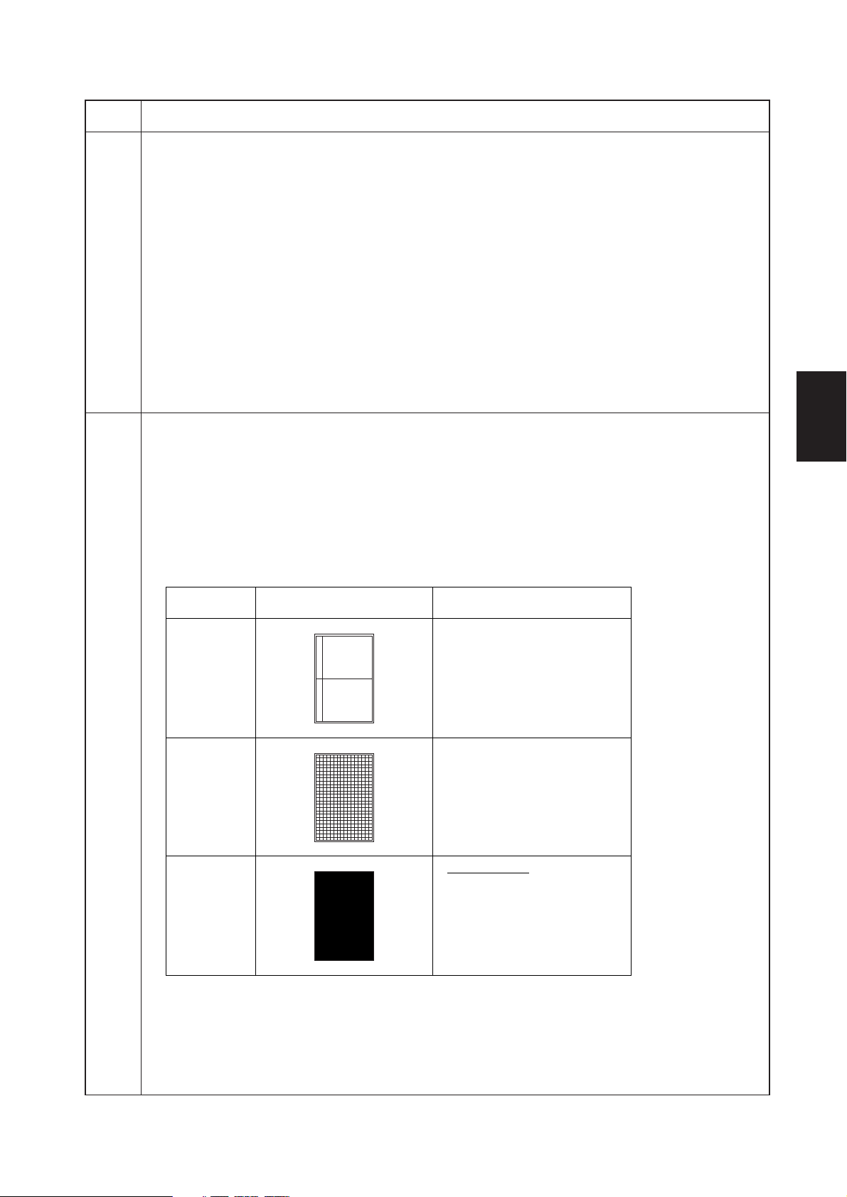
2AV/X
Maintenance
item No.
U992 Checking or clearing the printer/fax count
Description
Displays, clears or changes the print count of the printer or fax when the optional printer board or fax unit is
installed.
Purpose
To check the frequency of use of the printer or fax.
Method
Press the start key. The print count of the printer and fax are displayed.
Setting
1. Select the count to be cleared using the cursor up/down keys.
2. Enter a six-digit count using the numeric keys.
To clear the counts for both printer and fax, press the reset key.
3. Press the start key.
Completion
Press the stop/clear key. The screen for selecting a maintenance item No. is displayed.
U993 Outputting a VTC-PG pattern
Description
Selects and outputs a VTC-PG pattern created in the copier.
Purpose
When performing respective image printing adjustments, used to check the machine status apart from that
of the scanner with a non-scanned output VTC-PG pattern.
Method
1. Press the start key. The screen for selecting an item is displayed.
2. Select the VTC-PG pattern to be output using the cursor up/down keys.
Description
1-4
Display
VTC-PG1
VTC-PG2
VTC-PG3
3. Press the interrupt key. The copy mode screen is displayed.
4. Press the start key. A VTC-PG pattern is output.
Completion
Press the stop/clear key at the screen for selecting an item. The screen for selecting a maintenance item
No. is displayed.
PG pattern to be output Purpose
• Center line adjustment
• Lateral squareness adjustment
• Magnification adjustment
1-4-51
 Loading...