

Page 1

FS-C8500DN
SERVICE
MANUAL
Published in July 2010
842KA112
2KASM062
Rev. 2
Page 2

CAUTION
RISK OF EXPLOSION IF BATTERY IS REPLACED BY AN INCORRECT TYPE. DISPOSE OF
USED BATTERIES ACCORDING TO THE INSTRUCTIONS.
It may be illegal to dispose of this battery into the municipal waste stream. Check with your local
solid waste officials for details in your area for proper disposal.
ATTENTION
IL Y A UN RISQUE D’EXPLOSION SI LA BATTERIE EST REMPLACEE PAR UN MODELE DE
TYPE INCORRECT. METTRE AU REBUT LES BATTERIES UTILISEES SELON LES INSTRUCTIONS DONNEES.
Il peut être illégal de jeter les batteries dans des eaux d’égout municipales. Vérifiez avec les fonctionnaires municipaux de votre région pour les détails concernant des déchets solides et une mise
au rebut appropriée.
Page 3

Revision history
Revision Date Replaced pages Remarks
1 February 2, 2010 1-3-1 2 July 20, 2010 1-1-1, 1-1-2, 1-3-4, 1-3-27, 1-3-36, 1-3-37, 1-3-55, 1-3-86,
1-4-38, 1-4-39, 2-4-1, 2-4-2, 2-4-7
-
Page 4

This page is intentionally left blank.
Page 5

Safety precautions
This booklet provides safety warnings and precautions for our service personnel to ensure the safety of
their customers, their machines as well as themselves during maintenance activities. Service personnel
are advised to read this booklet carefully to familiarize themselves with the warnings and precautions
described here before engaging in maintenance activities.
Page 6
Safety warnings and precautions
Various symbols are used to protect our service personnel and customers from physical danger and
to prevent damage to their property. These symbols are described below:
DANGER: High risk of serious bodily injury or death may result from insufficient attention to or incorrect
compliance with warning messages using this symbol.
WARNING: Serious bodily injury or death may result from insufficient attention to or incorrect compliance
with warning messages using this symbol.
CAUTION: Bodily injury or damage to property may result from insufficient attention to or incorrect com-
pliance with warning messages using this symbol.
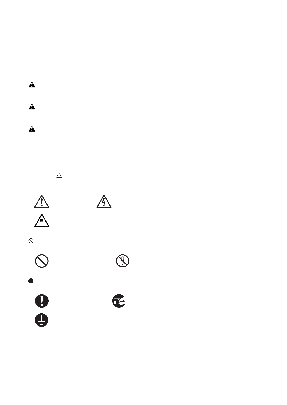
Symbols
The triangle ( ) symbol indicates a warning including danger and caution. The specific point of attention is
shown inside the symbol.
General warning. Warning of risk of electric shock.
Warning of high temperature.
indicates a prohibited action. The specific prohibition is shown inside the symbol.
General prohibited action. Disassembly prohibited.
indicates that action is required. The specific action required is shown inside the symbol.
General action required. Remove the power plug from the wall outlet.
Always ground the copier.
Page 7

1. Installation Precautions
WARNING
• Do not use a power supply with a voltage other than that specified. Avoid multiple connections to
one outlet: they may cause fire or electric shock. When using an extension cable, always check that
it is adequate for the rated current. .....................................................................................................
• Connect the ground wire to a suitable grounding point. Not grounding the copier may cause fire or
electric shock. Connecting the earth wire to an object not approved for the purpose may cause
explosion or electric shock. Never connect the ground cable to any of the following: gas pipes, lightning rods, ground cables for telephone lines and water pipes or faucets not approved by the proper
authorities. ..........................................................................................................................................
CAUTION:
• Do not place the copier on an infirm or angled surface: the copier may tip over, causing injury. .........
• Do not install the copier in a humid or dusty place. This may cause fire or electric shock. .................
• Do not install the copier near a radiator, heater, other heat source or near flammable material. This
may cause fire. ...................................................................................................................................
• Allow sufficient space around the copier to allow the ventilation grills to keep the machine as cool
as possible. Insufficient ventilation may cause heat buildup and poor copying performance. ............
• Always handle the machine by the correct locations when moving it. .................................................
• Always use anti-toppling and locking devices on copiers so equipped. Failure to do this may cause
the copier to move unexpectedly or topple, leading to injury. ..............................................................
• Avoid inhaling toner or developer excessively. Protect the eyes. If toner or developer is accidentally
ingested, drink a lot of water to dilute it in the stomach and obtain medical attention immediately.
If it gets into the eyes, rinse immediately with copious amounts of water and obtain medical atten-
tion. .....................................................................................................................................................
• Advice customers that they must always follow the safety warnings and precautions in the copier’s
instruction handbook. .........................................................................................................................
Page 8
2. Precautions for Maintenance
WARNING
• Always remove the power plug from the wall outlet before starting machine disassembly. ................
• Always follow the procedures for maintenance described in the service manual and other related
brochures. ..........................................................................................................................................
• Under no circumstances attempt to bypass or disable safety features including safety mechanisms
and protective circuits. ........................................................................................................................
• Always use parts having the correct specifications. ............................................................................
• Always use the thermostat or thermal fuse specified in the service manual or other related brochure
when replacing them. Using a piece of wire, for example, could lead to fire or other serious acci-
dent. ...................................................................................................................................................
• When the service manual or other serious brochure specifies a distance or gap for installation of a
part, always use the correct scale and measure carefully. ..................................................................
• Always check that the copier is correctly connected to an outlet with a ground connection. ...............
• Check that the power cable covering is free of damage. Check that the power plug is dust-free. If it
is dirty, clean it to remove the risk of fire or electric shock. .................................................................
• Never attempt to disassemble the optical unit in machines using lasers. Leaking laser light may
damage eyesight. ...............................................................................................................................
• Handle the charger sections with care. They are charged to high potentials and may cause electric
shock if handled improperly. ...............................................................................................................
CAUTION
• Wear safe clothing. If wearing loose clothing or accessories such as ties, make sure they are safely
secured so they will not be caught in rotating sections. ......................................................................
• Use utmost caution when working on a powered machine. Keep away from chains and belts. ..........
• Handle the fixing section with care to avoid burns as it can be extremely hot. ..................................
• Check that the fixing unit thermistor, heat and press rollers are clean. Dirt on them can cause
abnormally high temperatures. ...........................................................................................................
Page 9

• Do not remove the ozone filter, if any, from the copier except for routine replacement. ......................
• Do not pull on the AC power cord or connector wires on high-voltage components when removing
them; always hold the plug itself. ........................................................................................................
• Do not route the power cable where it may be stood on or trapped. If necessary, protect it with a
cable cover or other appropriate item. ................................................................................................
• Treat the ends of the wire carefully when installing a new charger wire to avoid electric leaks. ..........
• Remove toner completely from electronic components. .....................................................................
• Run wire harnesses carefully so that wires will not be trapped or damaged. ......................................
• After maintenance, always check that all the parts, screws, connectors and wires that were
removed, have been refitted correctly. Special attention should be paid to any forgotten connector,
trapped wire and missing screws. .......................................................................................................
• Check that all the caution labels that should be present on the machine according to the instruction
handbook are clean and not peeling. Replace with new ones if necessary. .......................................
• Handle greases and solvents with care by following the instructions below: ......................................
· Use only a small amount of solvent at a time, being careful not to spill. Wipe spills off completely.
· Ventilate the room well while using grease or solvents.
· Allow applied solvents to evaporate completely before refitting the covers or turning the power
switch on.
· Always wash hands afterwards.
• Never dispose of toner or toner bottles in fire. Toner may cause sparks when exposed directly to
fire in a furnace, etc. ...........................................................................................................................
• Should smoke be seen coming from the copier, remove the power plug from the wall outlet immedi-
ately. ...................................................................................................................................................
3. Miscellaneous
WARNING
• Never attempt to heat the drum or expose it to any organic solvents such as alcohol, other than the
specified refiner; it may generate toxic gas. ........................................................................................
Page 10

This page is intentionally left blank.
Page 11

CONTENTS
1-1 Specifications
1-1-1 Specifications..........................................................................................................................................1-1-1
1-1-2 Parts names............................................................................................................................................1-1-3
(1) Body ..................................................................................................................................................1-1-3
(2) Operation panel.................................................................................................................................1-1-6
1-1-3 Machine cross section ............................................................................................................................1-1-7
1-2 Installation
1-2-1 Installation environment ..........................................................................................................................1-2-1
1-2-2 Unpacking and installation ......................................................................................................................1-2-2
(1) Installation procedure ........................................................................................................................1-2-2
(2) Setting initial copy modes................................................................................................................1-2-11
1-2-3 Installing the cassette heater (option) (inch specifications only)...........................................................1-2-12
1-3 Maintenance Mode
1-3-1 Maintenance mode .................................................................................................................................1-3-1
(1) Executing a maintenance item ..........................................................................................................1-3-1
(2) Maintenance mode item list...............................................................................................................1-3-2
(3) Contents of maintenance mode items...............................................................................................1-3-7
1-3-2 Mode selection menu..........................................................................................................................1-3-105
(1) Using the menu mode ...................................................................................................................1-3-105
(2) Report Print ...................................................................................................................................1-3-106
(3) USB Memory.................................................................................................................................1-3-106
(4) Custom Box...................................................................................................................................1-3-107
(5) Job Box .........................................................................................................................................1-3-107
(6) Counter..........................................................................................................................................1-3-108
(7) Paper Settings...............................................................................................................................1-3-108
(8) Print Settings.................................................................................................................................1-3-109
(9) Network .........................................................................................................................................1-3-110
(10) Device Common............................................................................................................................1-3-110
(11) Security .........................................................................................................................................1-3-112
(12) Job Accounting settings ................................................................................................................1-3-112
(13) Administrator .................................................................................................................................1-3-113
(14) Adjust/Maintenance.......................................................................................................................1-3-113
1-3-3 Service mode ......................................................................................................................................1-3-115
(1) Executing a maintenance item ......................................................................................................1-3-115
(2) Description of service mode..........................................................................................................1-3-116
2KA
1-4 Troubleshooting
1-4-1 Paper misfeed detection .........................................................................................................................1-4-1
(1) Paper misfeed indication ...................................................................................................................1-4-1
(2) Paper misfeed detection conditions ..................................................................................................1-4-2
(3) Paper misfeeds ...............................................................................................................................1-4-10
1-4-2 Self-diagnosis .......................................................................................................................................1-4-20
(1) Self-diagnostic function ...................................................................................................................1-4-20
(2) Self diagnostic codes ......................................................................................................................1-4-23
1-4-3 Image formation problems ....................................................................................................................1-4-54
(1) No image appears (entirely white)...................................................................................................1-4-55
(2) No image appears (entirely black)...................................................................................................1-4-55
(3) Dirty on the back side......................................................................................................................1-4-56
(4) Image is too light. ............................................................................................................................1-4-56
(5) The background is colored. .............................................................................................................1-4-57
(6) A white line appears longitudinally. .................................................................................................1-4-57
(7) A line appears longitudinally............................................................................................................1-4-57
(8) A line appears laterally....................................................................................................................1-4-58
(9) Dots appear on the image...............................................................................................................1-4-58
(10) The leading edge of the image is consistently misaligned. .............................................................1-4-58
(11) The leading edge of the image is sporadically misaligned..............................................................1-4-58
(12) Paper creases. ................................................................................................................................1-4-59
(13) Offset occurs. ..................................................................................................................................1-4-59
Page 12

2KA
(14) Image is partly missing....................................................................................................................1-4-59
(15) Fusing is poor..................................................................................................................................1-4-60
(16) Image is out of focus. ......................................................................................................................1-4-60
(17) Colors are printed offset to each other. ...........................................................................................1-4-60
(18) Image center does not align with the original center.......................................................................1-4-60
1-4-4 Electric problems ..................................................................................................................................1-4-61
1-4-5 Mechanical problems ............................................................................................................................1-4-67
1-5 Assembly and Disassembly
1-5-1 Precautions for assembly and disassembly............................................................................................1-5-1
(1) Precautions .......................................................................................................................................1-5-1
(2) Drum..................................................................................................................................................1-5-1
(3) Toner .................................................................................................................................................1-5-1
(4) How to tell a genuine Kyocera Mita toner container ..........................................................................1-5-2
1-5-2 Paper feed section ..................................................................................................................................1-5-3
(1) Detaching and refitting the forwarding, paper feed and separation pulleys ......................................1-5-3
(2) Detaching and refitting the MP unit ...................................................................................................1-5-6
(3) Detaching and refitting the MP forwarding, MP paper feed and MP separation pulleys ...................1-5-8
1-5-3 Optical section ......................................................................................................................................1-5-11
(1) Detaching and refitting the laser scanner unit.................................................................................1-5-11
(2) Manual color registration adjustment ..............................................................................................1-5-19
1-5-4 Image formation section........................................................................................................................1-5-21
(1) Detaching and refitting the image formation holder.........................................................................1-5-21
(2) Detaching and refitting the developing unit .....................................................................................1-5-25
(3) Detaching and refitting the drum unit ..............................................................................................1-5-26
(4) Detaching and refitting the charger roller unit .................................................................................1-5-27
1-5-5 Transfer section ....................................................................................................................................1-5-28
(1) Detaching and refitting the transfer belt unit....................................................................................1-5-28
(2) Detaching and refitting the transfer roller ........................................................................................1-5-29
1-5-6 Fuser section ........................................................................................................................................1-5-31
(1) Detaching and refitting the fuser unit...............................................................................................1-5-31
1-5-7 Other .....................................................................................................................................................1-5-32
(1) Detaching and refitting the left filter, rear upper filter, right filter 1/2, rear lower filter, front filter
and duct filter...................................................................................................................................1-5-32
(2) Detaching and refitting the hard disk unit ........................................................................................1-5-34
(3) Detaching and refitting the left cover 1 (paper conveying unit) .......................................................1-5-37
(4) Direction of installing the principal fan motors.................................................................................1-5-42
1-6 Requirements on PWB Replacement
1-6-1 Upgrading the firmware...........................................................................................................................1-6-1
1-6-2 Remarks on main PWB replacement......................................................................................................1-6-2
1-6-3 Remarks on engine PWB replacement...................................................................................................1-6-4
2-1 Mechanical Construction
2-1-1 Paper feed section ..................................................................................................................................2-1-1
(1) Cassette paper feed section..............................................................................................................2-1-1
(2) MP tray paper feed section ...............................................................................................................2-1-3
2-1-2 Drum section...........................................................................................................................................2-1-6
(1) Drum section .....................................................................................................................................2-1-6
2-1-3 Developing section..................................................................................................................................2-1-8
(1) Developing section............................................................................................................................2-1-8
2-1-4 Optical section ......................................................................................................................................2-1-10
(1) Laser scanner section .....................................................................................................................2-1-10
2-1-5 Transfer/separation section ..................................................................................................................2-1-12
(1) Primary transfer section ..................................................................................................................2-1-12
(2) Secondary transfer/separation section............................................................................................2-1-14
2-1-6 Fuser section ........................................................................................................................................2-1-15
(1) Fuser section...................................................................................................................................2-1-15
2-1-7 Eject/feedshift section ...........................................................................................................................2-1-17
(1) Eject/feedshift section .....................................................................................................................2-1-17
2-1-8 Duplex section ......................................................................................................................................2-1-19
(1) Duplex section.................................................................................................................................2-1-19
Page 13

2-2 Electrical Parts Layout
2-2-1 Electrical parts layout ..............................................................................................................................2-2-1
(1) PWBs ................................................................................................................................................2-2-1
(2) Switches and sensors .......................................................................................................................2-2-4
(3) Motors ...............................................................................................................................................2-2-6
(4) Others................................................................................................................................................2-2-8
2-3 Operation of the PWBs
2-3-1 Power source PWB.................................................................................................................................2-3-1
2-3-2 Engine PWB............................................................................................................................................2-3-4
2-3-3 Main PWB .............................................................................................................................................2-3-20
2-3-4 Main front PWB.....................................................................................................................................2-3-27
2-3-5 Sub front PWB ......................................................................................................................................2-3-31
2-3-6 Feed PWB.............................................................................................................................................2-3-35
2-3-7 Operation panel PWB ...........................................................................................................................2-3-40
2-4 Appendixes
Maintenance parts list.............................................................................................................................2-4-1
Maintenance kits.....................................................................................................................................2-4-2
Periodic maintenance procedures ..........................................................................................................2-4-3
Chart of image adjustment procedures...................................................................................................2-4-7
Wiring diagram No.1 ...............................................................................................................................2-4-8
Wiring diagram No.2 ...............................................................................................................................2-4-9
Wiring diagram No.3 .............................................................................................................................2-4-10
Wiring diagram No.4 .............................................................................................................................2-4-11
Wiring diagram No.5 .............................................................................................................................2-4-12
Wiring diagram No.6 .............................................................................................................................2-4-13
Wiring diagram No.7 .............................................................................................................................2-4-14
Wiring diagram No.8 .............................................................................................................................2-4-15
2KA
INSTALLATION GUIDE
PAPER FEEDER
3000 SHEETS PAPER FEEDER
DOCUMENT FINISHER
3000 SHEETS DOCUMENT FINISHER
CENTER-FOLDING UNIT
MAILBOX
HOLE PUNCH UNIT
DUCT UNIT
Page 14

2KA
This page is intentionally left blank.
Page 15

2KA-2
1-1 Specifications
1-1-1 Specifications
Type................................................Desktop
Printing system ...............................Dry-type electrostatic transfer (laser) printing, tandem/intermediate transfer printing
Paper weight...................................Cassette: 60 - 163 g/m
MP tray: 60 - 220 g/m
Paper type ......................................Cassette: Plain, Rough, Vellum, Recycled, Preprinted, Bond, Color (Colour),
Prepunched, Letterhead, Thick, High Quality, Custom 1 - 8
(Duplex: Same as Simplex)
MP tray: Plain, Transparency (OHP film), Rough, Vellum, Labels, Recycled,
Preprinted, Bond, Cardstock, Color (Colour), Prepunched, Letterhead,
Thick, Coated, Envelope, High Quality, Custom 1 - 8
Paper size.......................................Cassette: A3, B4, A4, A4R, B5, B5R, A5, Ledger, Legal, Letter, LetterR, Statement,
Oficio II, 8.5 x 13.5", Folio, 8K, 16K, 16KR
MP tray: A3, B4, A4, A4R, B5, B5R, A5, B6, A6, Ledger, Legal, Letter, LetterR,
Executive, Statement, Oficio II, 8.5 x 13.5", Folio, 8K, 16K, 16KR,
Postcards (100 x 148 mm), Return postcard (148 x 200 mm),
Envelope DL, Envelope C5, Envelope C4, Envelope #10 (Commercial #10),
Envelope #9 (Commercial #9), Envelope #6 (Commercial #6 3/4), Monarch,
ISO B5, Youkei 2, Youkei 4
Printing speed.................................B/W printing Color printing
A4/Letter: 55 sheets/min. A4/Letter: 50 sheets/min.
A4R/LetterR: 37 sheets/min. A4R/LetterR: 33 sheets/min.
A3/Ledger: 28 sheets/min. A3/Ledger: 25 sheets/min.
B4/Legal: 28 sheets/min. B4/Legal: 25 sheets/min.
B5: 55 sheets/min. B5: 50 sheets/min.
B/W duplex printing Color duplex printing
A4/Letter: 43 sheets/min. A4/Letter: 41 sheets/min.
A4R/LetterR: 24 sheets/min. A4R/LetterR: 21 sheets/min.
A3/Ledger: 20 sheets/min. A3/Ledger: 17 sheets/min.
B4/Legal: 21 sheets/min. B4/Legal: 17 sheets/min.
B5: 47 sheets/min. B5: 41 sheets/min.
First print time.................................Room temperature 23
5.2 s or less (B/W)/6.7 s or less (Color)
Warm-up time .................................Room temperature 22
Power on: 57.5 s or less
Low power mode:25 s or less
Sleep mode: 57.5 s or less
Paper capacity ................................Cassette 1:
500 sh
250 sheets (80 g/m2, B4/Legal or more)
Cassette 2:500 sheets (80 g/m2)
MP tray:100 sheets (80 g/m
50 sheets (80 g/m2, B4/Legal or more)
Output tray capacity........................Top tray: 500 sheets (80 g/m2)
Photoconductor...............................a-Si (drum diameter 30 mm)
Image write system.........................Semiconductor laser and electrophotography
Charging system.............................Charging roller
Developing system .........................Hybrid developing
Developer: 2-component
Toner replenishing: Automatic from a toner container
Transfer system ..............................Primary: Transfer belt
Secondary: Transfer roller
Separation system..........................Separation electrode
Cleaning system .............................Blade and cleaning roller
Charge erasing system...................Exposure by cleaning lamp
Fusing system.................................Belt fusing
Heat source: Halogen heaters
Abnormally high temperature protection devices: thermostats
CPU ................................................PowerPC750GL (750 MHz)
Main memory ..................................Standard: 1 GB
Maximum: 2 GB
Hard disk.........................................160 GB
Resolution.......................................600 dpi
2
(Duplex: 60 - 163 g/m2)
2
C/73.4 F, 60% RH
C/71.6 F, 60% RH
eets (80 g/m2, A4/Letter or less),
2
, A
4/Letter or less),
1-1-1
Page 16

2KA-2
Operating system............................ Windows 2000/XP/Vista/7, Windows Server 2003/2008, Apple Macintosh OS 10.x
Interface..........................................Hi-speed USB: 1
Network interface: 1 (10 BASE-T/100 BASE-TX)
KUIO/W slot: 1 (option)
Operating environment ................... Temperature: 10 to 32.5
°C/50 to 90.5°F
Humidity: 15 to 80% RH
Altitude: 2500 m/8,202 ft maximum
Brightness: 1500 lux maximum
Dimensions .....................................605 (W) x 680 (D) x 691 (H) mm (main body only)
13/16" (W) x 26 3/4" (D) x 27 3/16" (H) (main body only)
23
Weight.............................................99 kg/217.8 lb
Space required................................889 mm (W) x 680 (D) mm (using MP tray)
35" (W) x 26
3/4" (D) (using MP tray)
Power source..................................120 V AC, 60 Hz, 12.0 A
220 to 240 V AC, 50/60 Hz, 7.2 A
Options ...........................................Paper feeder, 3000-sheet paper feeder, document finisher, 3000-sheet document fin-
isher, center-folding unit, mailbox, punch unit, data security kit and expansion memory
NOTE: These specifications are subject to change without notice.
1-1-2
Page 17
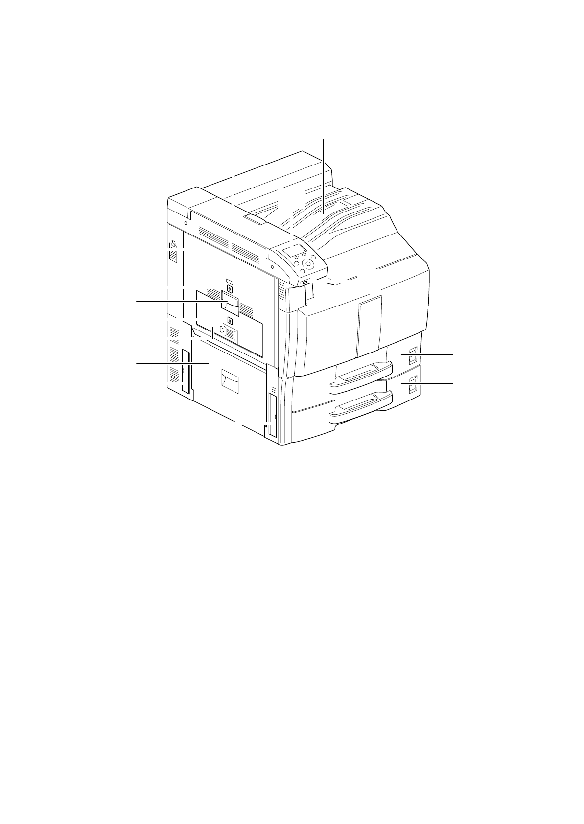
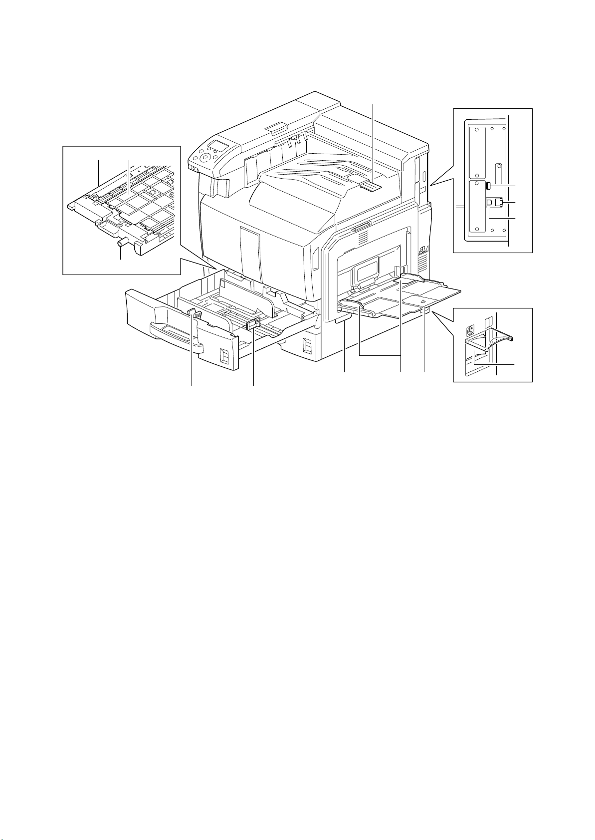
1-1-2 Parts names
1. Operation panel
2. USB memory slot
3. Front cover
4. Cassette 1
5. Cassette 2
6. Top cover
7. Top tray
8. Left cover 1
9. Left cover 1 indicator
10. Left cover 1 lever
11. Left cover 2 indicator
12. Left cover 2
13. Left cover 3
14. Handles
(1) Body
8
2KA
7
6
1
10
11
12
13
14
9
2
3
4
5
Figure 1-1-1
1-1-3
Page 18
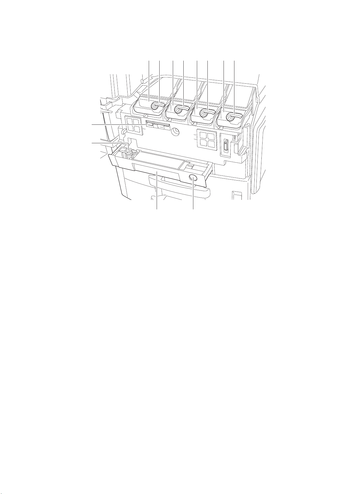
2KA
15. Toner container (Black)
16. Toner container release lever (Black)
17. Toner container (Yellow)
18. Toner container release lever (Yellow)
19. Toner container (Cyan)
20. Toner container release lever (Cyan)
21. Toner container (Magenta)
22. Toner container release lever (Magenta)
23. Cleaning brush
24. Waste toner box
25. Waste toner tray
26. Release button
2221201918171615
23
24
25
Figure 1-1-2
26
1-1-4
Page 19
35
27. Paper feed unit cover
28. Paper feed unit
29. Knob
30. Paper width adjusting tab
31. Paper length guide
32. MP tray (multi-purpose tray)
33. Paper width guides
34. Handles
35. Paper stopper
36. USB port
37. Network interface connector
38. USB interface connector
39. Main power switch
2KA
28
29
27
30
31
Figure 1-1-3
34 32
33
36
37
38
39
1-1-5
Page 20
2KA
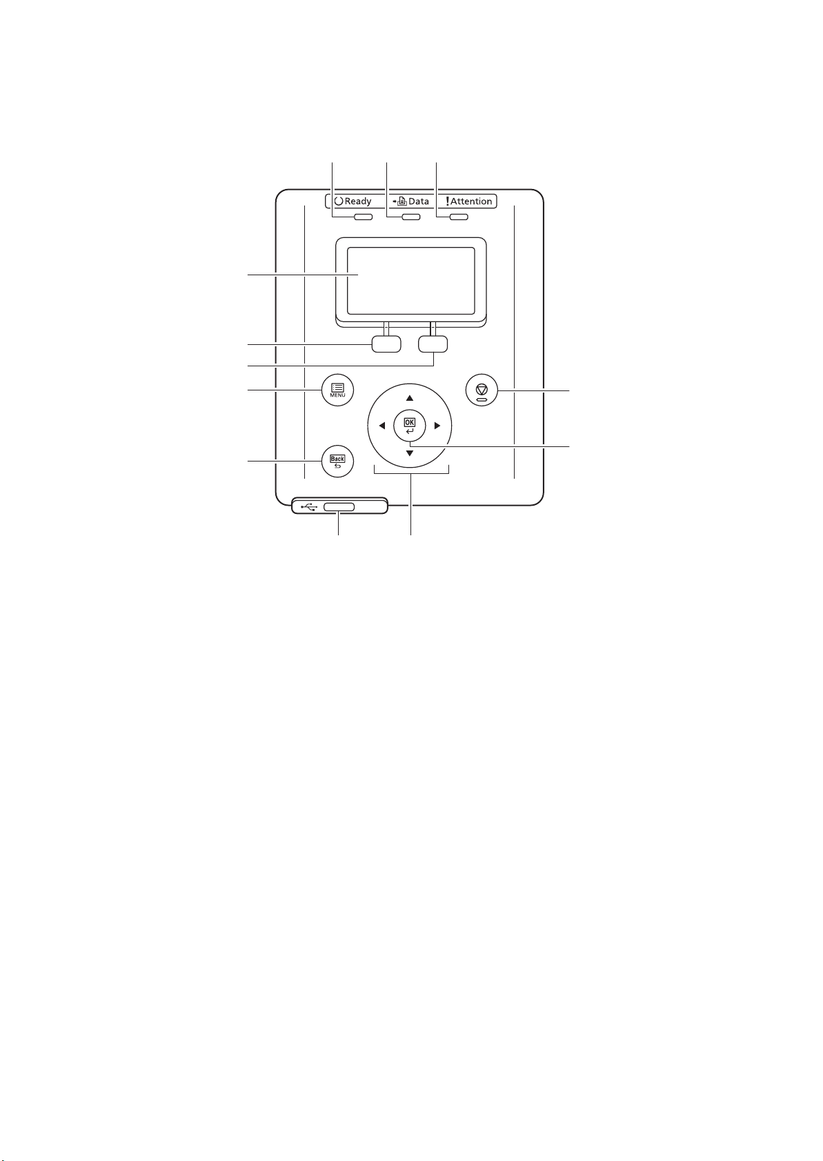
1. Ready indicator
2. Data indicator
3. Attention indicator
4. Message display
5. Left Select key
6. Right Select key
7. MENU key
8. Back key
9. Stop key
10. OK key
11. USB memory slot
12. Cursor up/down/left/right keys
(2) Operation panel
123
4
5
6
79
10
8
11 12
Figure 1-1-4
1-1-6
Page 21
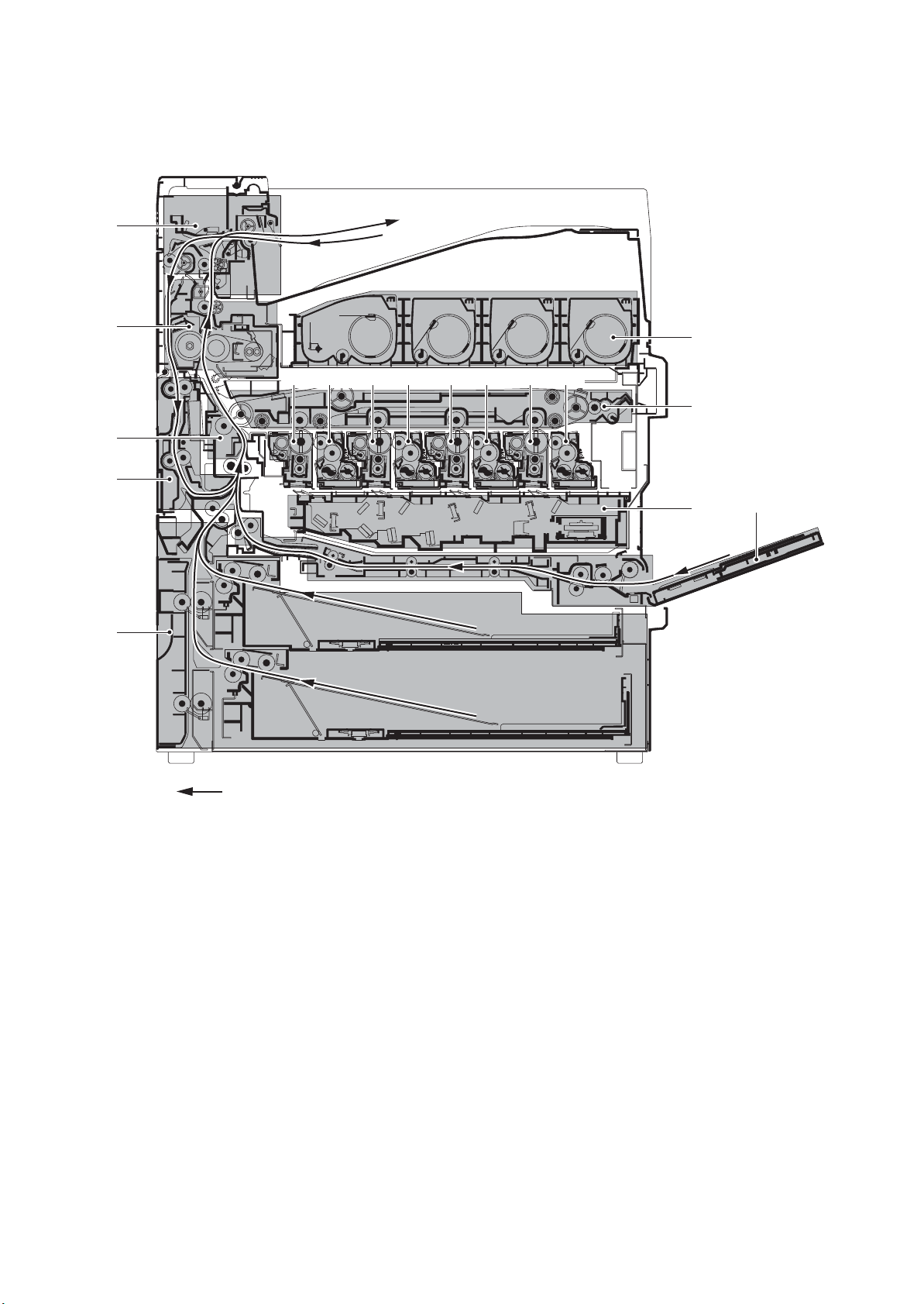
1-1-3 Machine cross section
1. Cassette paper feed section
2. MP tray paper feed section
3. Laser scanner section
4. Drum section (Black)
5. Drum section (Yellow)
6. Drum section (Cyan)
7. Drum section (Magenta)
8. Developing section (Black)
9. Developing section (Yellow)
10. Developing section (Cyan)
11. Developing section (Magenta)
12. Toner container section
13. Primary transfer section
14. Secondary transfer/separation section
15. Fuser section
16. Eject/feedshift section
17. Duplex section
16
2KA
15
14
17
12
4 8 5 9 6 10 7 11
13
3
2
1
Paper path
Figure 1-1-5 Machine cross section
1-1-7
Page 22

2KA
This page is intentionally left blank.
1-1-8
Page 23
1-2 Installation
1-2-1 Installation environment
1. Temperature: 10 to 32.5C/50 to 90.5F
2. Humidity: 15 to 80%
3. Power supply: 120 V AC, 12.0 A/220 to 240 V AC, 7.2 A
4. Power source frequency: 50 Hz
5. Installation location
Avoid direct sunlight or bright lighting. Ensure that the photoconductor will not be exposed to direct sunlight or
other strong light when removing paper jams.
Avoid locations subject to high temperature and high humidity or low temperature and low humidity; an abrupt
change in the environmental temperature; and cool or hot, direct air.
Avoid places subject to dust and vibrations.
Choose a surface capable of supporting the weight of the machine.
Place the machine on a level surface (maximum allowance inclination: 1
Avoid air-borne substances that may adversely affect the machine or degrade the photoconductor, such as mercury, acidic of alkaline vapors, inorganic gasses, NOx, SOx gases and chlorine-based organic solvents.
Select a well-ventilated location.
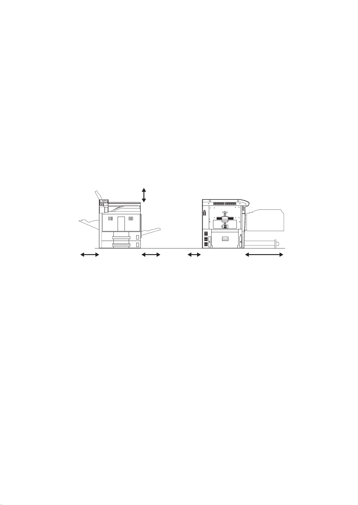
6. Allow sufficient access for proper operation and maintenance of the machine.
Machine front: 1000 mm/39
Machine right: 300 mm/11 13/16" Machine left: 300 mm/11 13/16"
2%/60 Hz 2%
°).
3/8" Machine rear: 100 mm/3 15/16"
2KA
13/16
400 mm/15
"
300 mm/11
3/4
"
13/16
" 100 mm/3
15/16
" 1000 mm/39
3/8
"300 mm/11
Figure 1-2-1 Installation dimensions
1-2-1
Page 24
2KA
1-2-2 Unpacking and installation
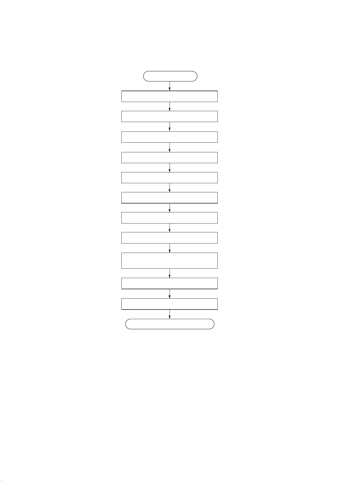
(1) Installation procedure
Start
Unpacking.
Removing the protective sheet.
Installing the paper feeder (option).
Release of lift plate stopper.
Installing the toner containers.
Installing the waste toner box.
Loading paper.
Install other optional devices.
Connecting the cassette heater.
(metric specifications only)
Connecting the power cord.
Adjusting the image.
Completion of the machine installation.
1-2-2
Page 25

2KA
Moving the machine
When moving the machine, pull out two carrying handles on the left side, and move with carrying handles and the handhold two place of the right side.
DP
A2
B1
Carrying
handle
Carrying
handle
Handhold
Handhold
Figure 1-2-2
1-2-3
Page 26
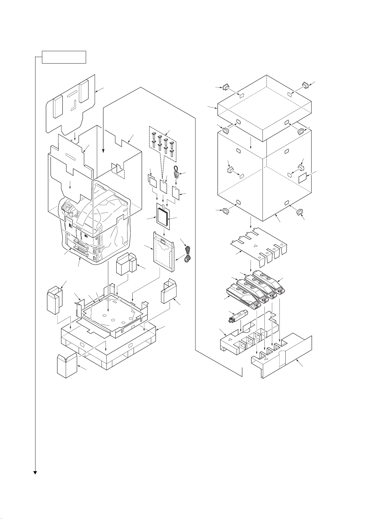
2KA
Unpacking.
1. Machine
2. Upper lid
3. Outer case
4. Inner frame
5. Upper left pad
6. Upper right pad
7. Skid
8. Bottom sheet
9. Bottom pad
10. Plastic bag
11. Bottom front left pad
12. Bottom front right pad
13. Bottom rear left pad
14. Bottom rear right pad
15. Left pad
16. Front pad
17. Machine cover
18. Document tray
19. Power code
20. Plastic bag
21. Operation guide
22. Plastic bag
23. Jumper connector
24. Plastic bag
25. Cursor pins
26. Size plates
27. Barcode label
28. Hinge joints
29. Upper pad
30. Toner container K
31. Toner container Y
32. Toner container M
33. Toner container C
34. Waste toner box
15
28
28
2
25
28
28
4
16
28
28
26
24
23
27
22
28
20
21
3
28
19
18
1
17
13
11
10
9
8
31
29
32
33
30
14
34
Place the machine on a level surface.
1-2-4
12
7
Figure 1-2-3 Unpacking
5
6
Page 27
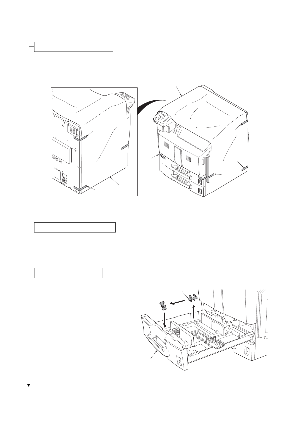
1. Remove six tapes and then remove the pro-
Removing the protective sheet.
Installing the paper feeder (option).
Release of lift plate stopper.
tective sheet.
2KA
Protective sheet
Ta pe
Ta pe
Ta pe
Ta pe
Protective
sheet
Figure 1-2-4
1. Install the optional paper feeder as necessary.
2. Verify levelness using a level gauge, and adjust the level bolts at the bottom of the machine to
optimize levelness.
Ta pe
Ta pe
1. Pull cassette 1 and 2 out.
Remove the lift plate stopper from each cassette and attach it to the storage location.
When moving the machine, attach the lift
plate in original position.
2. Gently push cassette 1 and 2 back in.
Lift plate stopper
Cassette
Figure 1-2-5
1-2-5
Page 28
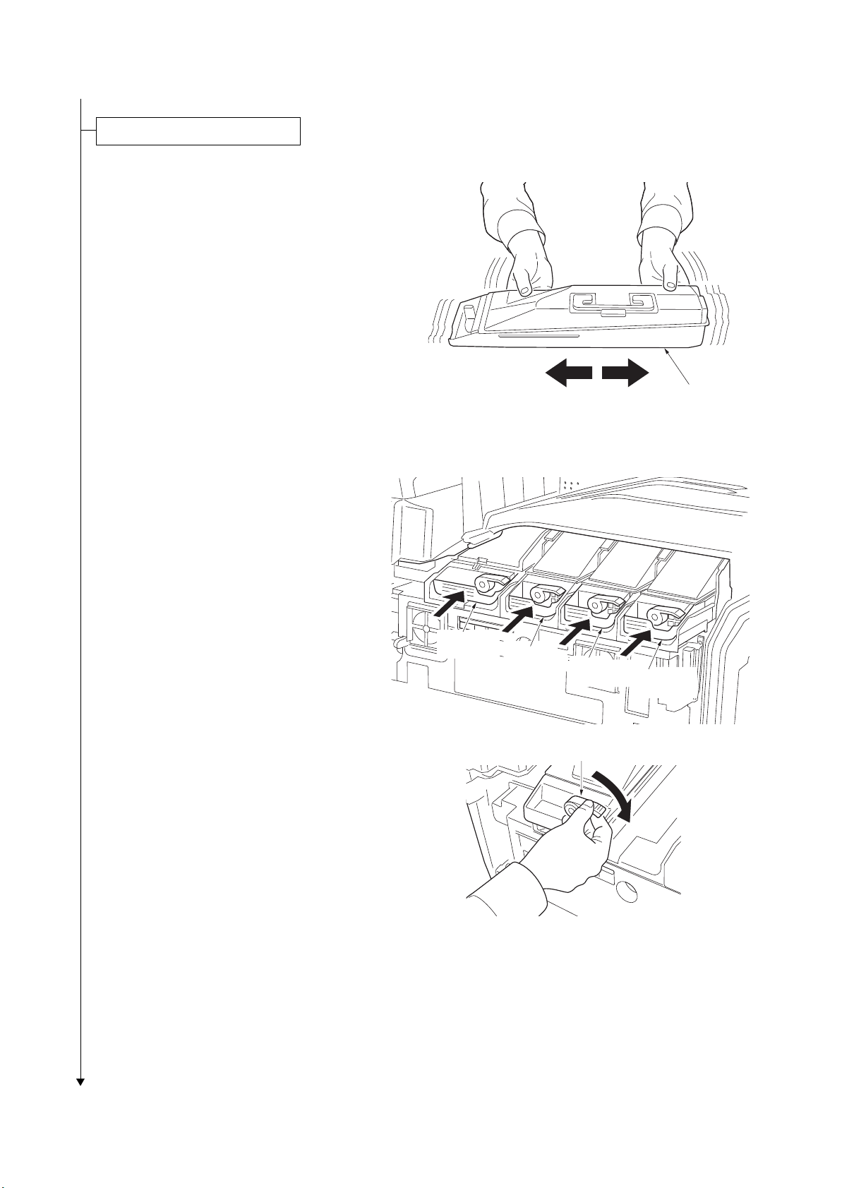
2KA
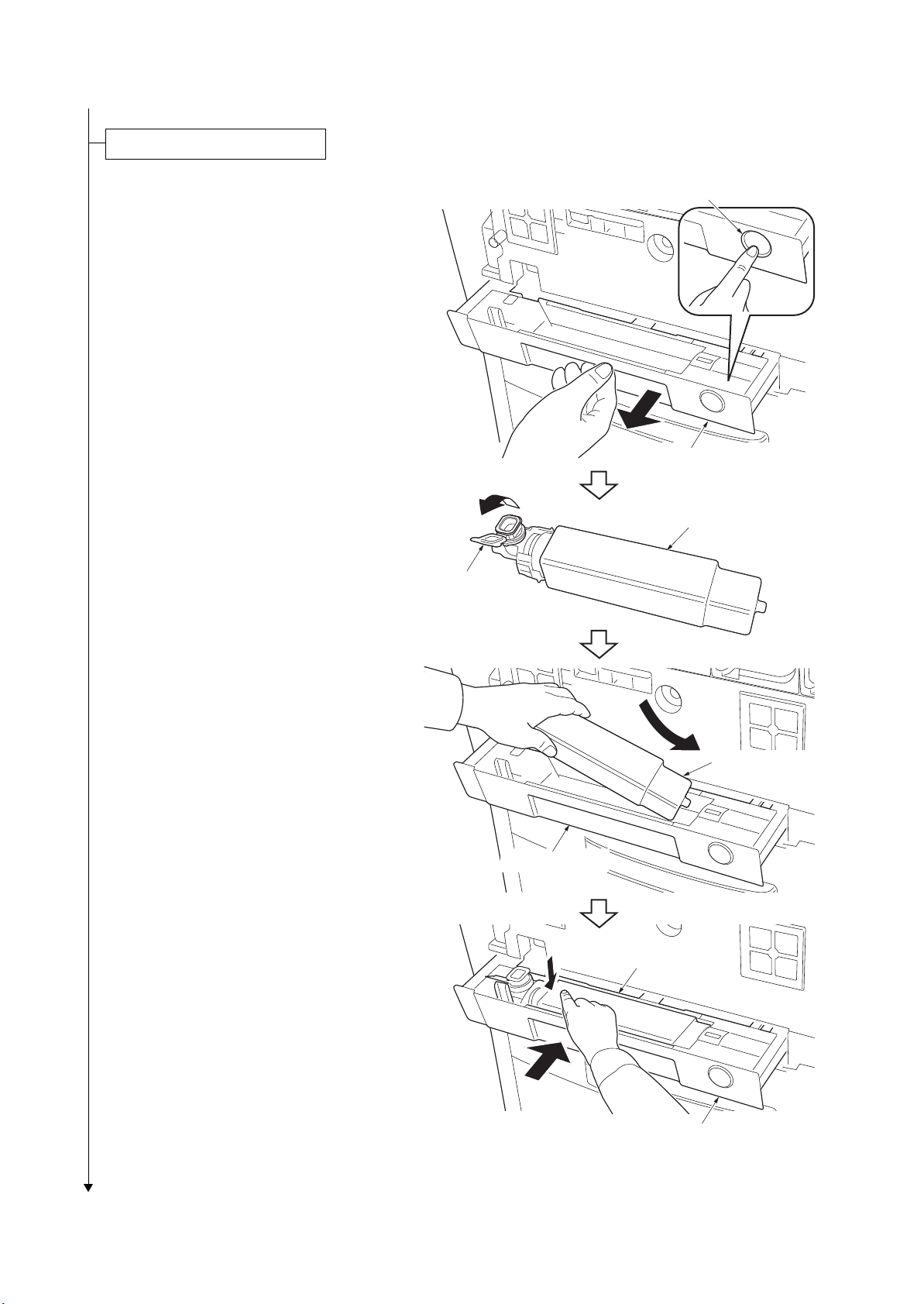
Installing the toner containers.
r
1. Open the front cover.
2. Hold the toner container with the toner con-
tainer release lever positioned on the top,
and shake the toner container in the horizontal direction.
Toner containe
Figure 1-2-6
3. Install four color toner containers.
4. Turn down the toner container release
levers to lock the four color toner containers.
Toner
container K
Toner
container Y
Toner container
release lever
Toner
container C
Toner
container M
1-2-6
Figure 1-2-7
Page 29
2KA
Installing the waste toner box.
1. Push the release button and pull out the
waste toner tray.
2. Open the lid and install the waste toner box.
3. Push the waste toner tray back in.
4. Close the front cover.
Release button
Waste toner tray
Waste toner box
Lid
Waste toner tray
Waste toner box
Waste toner box
Waste toner tray
Figure 1-2-8
1-2-7
Page 30
2KA
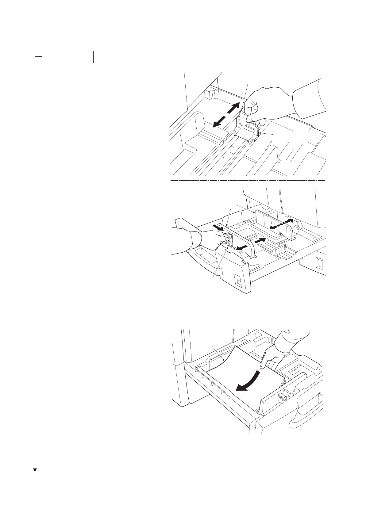
Loading paper.
1. Pull the cassette out.
2. Adjust the paper length guide to fit the paper
size.
3. Holding the paper width adjusting tab both
ends, move the paper width guide to fit the
paper.
4. When loading paper smaller than A4 or Let-
ter into cassette 1, raise the support lever as
shown in the figure.
Support lever
Paper length guide
Paper width
guides
5. Align the paper flush against the left side of
the cassette.
IMPORTANT: Verify that the paper is
pressed snugly against the vertical and horizontal size guides. If a gap is present, reset
the width guides or length guide.
Before loading the paper, be sure that it is
not curled or folded.
Ensure that the loaded paper does not
exceed the level indicated.
6. Insert the appropriate size plate in the slot to
indicate the size of the loaded paper.
7. Gently push the cassette back in.
Paper width
adjusting tab
Figure 1-2-9
Paper
Figure 1-2-10
1-2-8
Page 31

1. Install the optional devices (document fin-
Install other optional devices.
Connecting the cassette heater. (metric specifications only)
isher etc.) as necessary.
1. Remove two screws and then remove the
lid.
2. Pull the connector of the cassette heater
wire out from the aperture.
3. Connect the jumper connector to the con-
nector of the cassette heater wire.
4. Seat the cassette heater wire into the
machine inside.
5. Refit the lid.
6. Run maintenance item U327 and select
“Mode” and set “M2”.
2KA
Screws
Cassette
heater wire
Aperture
Connector
Jumper connector
Lid
Cassette
heater wire
Connector
Figure 1-2-11
1-2-9
Page 32

2KA
Connecting the power cord.
Adjusting the image.
Completion of the machine installation.
1. Connect the power cord to the power cord connector on lower left of the machine.
2. Connect the power plug to the wall outlet.
1. Open the main power switch cover and turn the main power switch on.
2. Performing color registration (see page 1-3-113)
Select [Color Regist.] and press OK key.
Select [Normal] and perform [Print Chart].
Select [Adjust Magenta], [Adjust Cyan] and [Adjust Yellow], and enter the each values.
Check the output again of color registration chart and if the adjustments are incorrect, proceed to color registration and adjust again.
3. Performing Color adjustment (see page 1-3-113)
Select {Color Calibration] and press OK key.
Press [Yes] to perform Color Calibration.
Press Menu key to exit.
4. Setting the delivery date
Enter the maintenance mode.
Enter 278 and press the OK key.
Select [Today].
Press the OK key. The delivery date is set.
Press the Back key to exit.
5. Output status report
Enter 000 and press the OK key.
Select [Maintenance].
Press the OK key. A status report is output.
Press the Back key to exit.
6. Enter 001, then press the OK key to exit the maintenance mode.
1-2-10
Page 33

(2) Setting initial copy modes
Factory settings are as follows:
Maintenance item No. Contents Factory setting
U253 Switching between double and single counts Double (A3/LD)
U260 Selecting the timing for copy counting Eject
U285 Setting service status page On
U325 Setting the paper interval On/1
U327 Setting the cassette heater control Off/Off
U328 Side ejection setting Off
2KA
1-2-11
Page 34

2KA
1-2-3 Installing the cassette heater (option) (inch specifications only)
Installing the cassette heater requires the following component:
Cassette heater (P/N 302H794760)
Two (2) M4 x 10 screws (P/N 7BB700410H)
Procedure
1. Turn the main power switch off. And then
unplug the power cable from the wall outlet.
2. Remove cassette 1 and 2.
3. Remove the screw and then remove the
connector cover.
4. Place the cassette heater by engaging it
with the four hooks.
5. Fit the cassette heater using two screws.
Screw
Connector cover
Hook
Hook
Hook
Cassette heater
Hook
Screw
Screw
Cassette heater
Figure 1-2-12
1-2-12
Page 35

6. Fasten the cassette heater wires to eight
wire saddles.
7. Connect two connectors of cassette heater
wires to each connector of the machine.
8. Refit the connector cover.
9. Refit the cassette 1 and 2.
2KA
Wire saddles
Wire saddles
Wire saddles
Wire saddles
Cassette heater
wires
10. Turn the main power switch on and enter the
maintenance mode.
11. Run maintenance item U327 and select
“Mode” and set “M2”.
Connector
Connector
Connector
Cassette heater
Connector
Figure 1-2-13
1-2-13
Page 36

2KA
This page is intentionally left blank.
1-2-14
Page 37

1-3 Maintenance Mode
While pressing the OK key and
the cursor down key, press the Menu key.
Enter the maintenance item
number using the cursor up/down keys.
Enter 001 using the cursor
up/down keys and press the OK key.
Enter 10871087 by pressing the OK key
every time after shifting the cursor
using cursor left/right leys.
The selected maintenance item is run.
Press the Back key.
Press the OK key.
Start
Maintenance mode is entered.
The maintenance item is
selected.
Maintenance mode is exited.
Repeat the same
maintenance item?
Run another maintenance
item?
Press the Right Select key for [Enter].
No
No
Yes
Yes
End
1-3-1 Maintenance mode
The machine is equipped with a maintenance function which can be used to maintain and service the machine.
(1) Executing a maintenance item
2KA-1
1-3-1
Page 38

2KA
(2) Maintenance mode item list
Section
General U000 Outputting an own-status report -
Initialization U021 Memory initializing -
Drive, paper
feed and
paper conveying system
Optical U089 Outputting the MIP-PG pattern High
voltage
Item
No.
U001 Exiting the maintenance mode U002 Setting the factory default data U004 Setting the machine number U019 Displaying the ROM version -
U024 HDD formatting U030 Checking the operation of the motors U031 Checking switches and sensors for paper conveying U032 Checking the operation of the clutches U033 Checking the operation of the solenoids U034 Adjusting the print start timing
LSU Out Top 0/0/0/0/0/0/0/0/0/0/0/0
LSU Out Left 0/0/0/0/0/0
LSU Out Top B/W 0/0/0/0/0/0
U035 Setting the printing area for folio paper 330/210
U037 Checking the operation of the fan motors U051 Adjusting the deflection in the paper
Bending Amt -1/7/1/13/-2/8/-1/-2/0/4/-2/-1
Bending Amt B/W -1/1/-1/0
U052 Setting the fuser motor control
Loop Sensor -
Loop Sensor Ctrl OFF/ON/ON/ON
U053 Setting the adjustment of the motor speed
Set Motor1 9/9/9/9/47/47/47/47
Set Motor2 0/0/0/0/0/0/0
Set Motor3 0/0/0/80/0/0
Set Motor4 21
Set Motor5 0/0/0/0/0
Set Motor6 0/0/0/50/0
U059 Setting fan mode Mode1/0/Mode2/0
U100 Adjusting main high voltage
Adjust MC AC Bias -
Set AC Auto Adj. On
Check DC1 Bias -
Adjust DC2 Bias 0/0/0/0/0/0/0/0/0
Set L.Temp.(Drum) 1
Set Charger Freq. 31449/28544
Content of maintenance item
Initial
setting*
*: Factory initial setting, *1: The item initialized for executing U021
1-3-2
Page 39

2KA
Section
High
voltage
Developing U131 Adjusting the toner sensor control voltage
Item
No.
U101 Setting the voltage for the primary transfer
Normal 116/90/120
Add Color 5/5/20/0/-5/-5/-15
Surround Correct On
U106 Setting the voltage for the secondary transfer
Light, Normal 1/(Full) Front 130/115/100/90
Light, Normal 1/(Full) Back 150/125/85/75
Light, Normal 1/(Full) Front B/W 150/115/110
Light, Normal 1/(Full) Back B/W 130/110/75
Normal 2-3/(Full) Front 150/125/110
Normal 2-3/(Full) Back 130/110/90
Normal 2-3/(Full) Front B/W 150/115/110
Normal 2-3/(Full) Back B/W 130/110/75
Heavy 1-3/(Half) Front 125/90/80
Heavy 1-3/(Half) Back 150/100/65
OHP 110/60
Bias 190/190/31/31/31
U107 Setting the transfer cleaning voltage
Belt Clean A (F) 93/93/93
Belt Clean A (H) 62/62/62
Belt Clean A B/W 120/120/120
Belt Clean B 150/120/150
U108 Setting separation shift bias
Set Output Value 85/60/52/60/8/26
Set Timing -150/0/40
U109 Checking the drum type U110 Checking the drum count U111 Checking the drum drive time U117 Checking the drum number U118 Displaying the drum history U119 Setting the drum U122 Checking the transfer belt unit number U123 Displaying the transfer belt unit history U127 Checking/clearing the transfer count U128 Setting transfer high-voltage timing -54/-54/10
Set Ope. Mode Automatic adjustment
Manual Adj. 116/116/116/116
Auto Adj. U132 Replenishing toner forcibly U135 Checking toner motor operation -
Content of maintenance item
Initial
setting*
85/60/52/60
*: Factory initial setting, *1: The item initialized for executing U021
1-3-3
Page 40

2KA-2
Section
Item
No.
Content of maintenance item
Initial
setting*
Developing U136 Setting toner near end detection 3/3
U139 Displaying the temperature and humidity outside the
machine
U140 Displaying developing bias
Dev Roll2 DC 93/93/93/93/93
Dev Roll1(Calb)DC 112/142/173/204/
112/142/173/204
Dev Roll2 AC 174/174/174/174/174
Dev Roll1DC 162/162/162/162/162
Roll1 DC Int 1/64/64/64/1
Dev Roll1AC 255/255/255/255/255
Dev Roll Freq 858/858/858/858/791
DEV Roll Duty 592/592/592/592/546
Dev Roll2 Duty 353/353/353/353/320
U147 Setting for toner applying operation
Operation Mode M1
Operation Value 50/5.0/60/M1/10/20
U148 Setting drum refresh mode U155 Displaying the toner sensor output U156 Setting the toner replenishment level
Supply Level 502/502/502/502/502
Empty Level 101/101/101/101/101
U157 Checking the developing drive time U158 Checking the developing count -
Fuser U161 Setting the fuser control temperature
Ready Temp. 165
Stable (Drv) 170
Stable (Stop) 170
Full Prt 170
Shift Prt Dup -5
Roller Temp. 140
U163 Resetting the fuser problem data U167 Checking/clearing the fuser count U199 Displaying fuser heater temperature -
Operation
panel and
support
equipment
U208 Setting the paper size for the paper feeder Letter (Inch)/A4 (Metric)
U221 Setting the USB host lock function Off
U223 Operation panel lock Unlock
U234 Setting punch destination Inch (Inch)/Europe (Metric)
U237 Setting finisher stack quantity 0/0
U240 Checking the operation of the finisher U241 Checking the operation of the switches of the finisher -
-
*1
*1
*1
*1
*1
*1
*1
*1
*1
*1
*: Factory initial setting, *1: The item initialized for executing U021
1-3-4
Page 41

2KA
Section
Operation
panel and
support
equipment
Item
No.
Content of maintenance item
U246 Setting the finisher
3000 Finisher 0/0/0/0/0/0
Booklet Fold 0/0/0/0/0/0/0/0
Initial
setting*
U247 Setting the paper feed device -
Mode setting U250 Change the maintenance count pre-set -
U251 Checking/clearing the maintenance count U252 Setting the destination U253 Switching between double and single counts Double (A3/LD)
U260 Selecting the timing for copy counting Eject
U265 Setting OEM purchaser code U278 Setting the delivery date U285 Setting service status page On
U325 Setting the paper interval On/1
U327 Setting the cassette heater control Off/Off
U328 Side ejection setting Off
U332 Setting the size conversion factor 1.0
U345 Setting the value for maintenance due indication 0
Image
processing
U464 Setting the ID correction operation
Permit On
Time Interval 480
Slp Period Calib 60
Permit Act(50pp) On
Permit(On/SlpOut) On
Permit(AP/NE) On
Calib Tmg Prt 1800
Calib Drv Time 600
Calib Prt Rate 20
Custom Off
AC Calib Target Value 500/500/500/10/
300/300/300/300
AC Calib Mag 3/3/3/3
Calib Prt Rate(H) 10
Calib Tmg Prt(H) 600
AC Calib Type Mode1
Prt Rate B/W 50
U465 Data reference for ID correction U467 Setting the color registration adjustment
Color Reg Adj On
T.B. Speed Adj On
Set Timing 10
*1
*1
*1
*1
*1
*1
*: Factory initial setting, *1: The item initialized for executing U021
1-3-5
Page 42

2KA
Section
Image
processing
Other U901 Checking copy counts by paper feed locations -
Item
No.
U473 Adjusting laser power output
Sensitivity LSU LD Power 16/16/16/16/16
Correction On
Density Adjust Emit Time/Dot All/0
U474 Checking LSU cleaning operation 1000/On
U486 Setting color/black and white operation mode Mode2
U902 Checking/clearing finisher punch count U903 Checking/clearing the paper jam counts U904 Checking/clearing the call for service counts U905 Checking counts by optional devices U906 Resetting partial operation control U908 Checking the total counter value U910 Clearing the coverage data U911 Checking copy counts by paper sizes U917 Setting backup data reading/writing U920 Checking the copy counts U927 Clearing the all copy counts and machine life counts (one
time only)
U928 Checking machine life counts U930 Checking/clearing the charger roller count U964 Checking of log U969 Checking of toner area code U977 Data capture mode U984 Checking the developing unit number U985 Displaying the developing unit history U996 Setting the Self-diagnostic function mode -
Content of maintenance item
Initial
setting*
-
*: Factory initial setting, *1: The item initialized for executing U021
1-3-6
Page 43

(3) Contents of maintenance mode items
Display Output list
Maintenance List of the current settings of the maintenance modes
User Status Outputs the user status page
Svc Status Outputs the service status page
Event Outputs the event log
NW Status Outputs the network status page
All Outputs the all reports
Display Output list
Print Outputs the report
USB(Text) Sends output data to the USB memory (text type)
USB(Html) Sends output data to the USB memory (HTML type)
2KA
Maintenance
item No.
U000
Description
Outputting an own-status report
Description
Outputs lists of the current settings of the maintenance items, and paper jam and service call occurrences.
Outputs the event log or service status page. Also sends output data to the USB memory.
Purpose
To check the current setting of the maintenance items, or paper jam or service call occurrences. Before initializing or replacing the backup RAM, output a list of the current settings of the maintenance items to reenter the
settings after initialization or replacement.
Method
1. Press the OK key.
2. Select the item to be output.
3. Press the OK key. The interrupt print mode is entered and a list is output.
When A4/Letter paper is available, a report of this size is output. If not, specify the paper feed location.
Method: Send to the USB memory
1. Turn the main power switch off.
2. Insert USB memory in USB memory slot.
3. Turn the main power switch on.
4. Enter the maintenance item.
5. Press the OK key.
6. Select the item to be send.
7. Press the OK key.
8. Select [Text] or [Html].
9. Press the OK key.
Output will be sent to the USB memory.
1-3-7
Page 44

2KA
No. Items Description
(1) System version
(2) System date
(3) Engine soft version
(4) Engine boot version
(5) Controller BROM version
(6) Operation panel mask version
(7) Machine serial number
Maintenance
item No.
U000
Event log
(1)
(8)
(12)
(f) (g) (h)
Event Log
Printer
Firmware version 2KA_2000.000.000 2009.10.27
Paper Jam Log
#
Count.
16
1876543
15
166554
14
4988
13
4988
12
4988
11
4988
10
110 3
9
110 3
8
110 3
7
110 3
6
1027
5
1027
4
1027
3
1027
2
406
1
36
Counter Log
J04:000
J05:000
J09:000
J10:000
J11:002
J20:000
J21:000
J22:000
J23:000
J30:002
J40:002
Event
Descriprions
10.01.08.01.01
10.01.08.01.02
10.01.08.01.01
10.01.08.01.02
10.01.08.01.01
10.01.08.01.02
10.01.08.01.01
10.01.08.01.01
(a) (b) (c) (d) (e)
10.01.08.01.01
12.03.08.01.01
12.03.08.01.01
12.03.08.01.01
12.03.0A.01.01
12.03.08.01.01
12.03.08.01.02
12.03.0A.01.01
12.03.08.01.01
J70:000
J71:000
J72:000
J73:000
J74:002
J75:002
J76:000
J93:002
J94:000
J95:000
J96:000
Description
(9)
(10)
(11)
C0100:001
C1010:001
C1020:001
C1030:001
C1040:001
(2)
27/Oct/2009 08:40
(4)(3) (5) (6)
[XXXXXXXX][XXXXXXXX] [XXXXXXXX] [XXXXXXXX]
Service Call Log
#
Count.
8
1881214
7
178944
6
5296
5
5295
4
2099
3
1054
2
809
1
30
Service Code
F0.0030
01.1010
F0.4000
F0.3100
01.2000
01.2000
01.2500
01.2500
Maintenance Log
#
Count.
8
1045571
7
104511
6
7045
5
3454
4
3454
3
3454
2
417
1
34
Item
01.00
01.00
01.00
01.00
02.00
02.00
02.00
02.20
Unknown toner Log
#
5
4
3
2
1
C4000:001
C4010:001
C4100:001
C6000:001
C6020:001
Count.
3454
3454
3454
406
32
Item
01.00
01.00
01.00
01.00
01.00
C8020:001
C8030:001
C8040:001
C8050:001
C8060:001
M00:01
M00:01
Figure 1-3-1
Detail of event log
1-3-8
[XXXXXXXXXXXXXXXX]
(7)
Page 45

2KA
No. Items Description
(8) Paper Jam Log # Count. Event
Remembers 1 to 16 of
occurrence. If the
occurrence of the previous paper jam is less
than 16, all of the paper
jams are logged. When
the occurrence
excesseds 16, the oldest occurrence is
removed.
The total page count at
the time of the paper
jam.
Log code (2 digit, hexadecimal, 5 categories)
(a) Cause of a paper
jam
(b) Paper source
(c) Paper size
(d) Paper type
(e) Paper eject
(a) Cause of paper jam (Hexadecimal)
00: Initial JAM
04: Cover open JAM
05: Secondary paper feed does not start
09: Sequence error JAM
10: No paper feed from cassette 1
11: No paper feed from cassette 2
12: No paper feed from optional cassette 3
13: No paper feed from optional cassette 4
14: No paper feed from MP tray
15: Misfeed in paper feeder horizontal paper conveying section 1
16: Misfeed in paper feeder horizontal paper conveying section 2
17: Misfeed in paper feeder horizontal paper conveying section 3
18: Misfeed in vertical paper conveying section
19: Misfeed in paper feeder paper conveying section
21: Multiple sheets in MP tray paper feed section
22: Multiple sheets in cassette 1 paper feed section
23: Multiple sheets in cassette 2 paper feed section
24: Multiple sheets in cassette 3 paper feed section
25: Multiple sheets in cassette 4 paper feed section
26: Multiple sheets in MP tray paper feed section
30: Misfeed in registration/transfer section
31: Misfeed round the transfer belt
40: Misfeed in fuser section (MP tray)
41: Misfeed in fuser section (cassette 1)
42: Misfeed in fuser section (cassette 2)
43: Misfeed in fuser section (cassette 3)
44: Misfeed in fuser section (cassette 4)
45: Misfeed in fuser section (3000-sheet paper feeder)
46: Misfeed in fuser section (duplex section)
50: Misfeed in eject section
52: Misfeed in feedshift section
60: Misfeed in duplex paper conveying section 1
61: Misfeed in duplex paper conveying section 2
80: Jam between the finisher and machine
81: Paper entry sensor non arrival jam
82: Jam in stapler
83: Eject sensor stay jam
84: Jam in eject section of right sub tray (3000-sheet document finisher)
85: Jam in eject section of left sub tray (3000-sheet document finisher)
87: Jam in eject section of inner tray 2 (3000-sheet document finisher)
88: Jam in eject section of main tray (3000-sheet document finisher)
89: Jam in center-folding unit (3000-sheet document finisher)
Maintenance
item No.
U000
Description
1-3-9
Page 46

2KA
No. Items Description
(8)
cont.
Paper Jam Log 90: Jam in mailbox (3000-sheet document finisher)
91: Finisher cover open
92: Eject paper sensor non-arrival jam (document finisher)
93: Reverse sensor jam (document finisher)
94: Paper entry sensor stay/remaining jam (document finisher)
95: Paper conveying sensor jam (document finisher)
(b) Detail of paper source (Hexadecimal)
00: MP tray
01: Cassette 1
02: Cassette 2
03: Cassette 3 (paper feeder)
04: Cassette 4 (paper feeder)
08: 3000-sheet paper feeder
05/06/07/09: Reserved
(c) Detail of paper size (Hexadecimal)
00: (Not specified)
01: Monarch
02: Business
03: International DL
04: International C5
05: Executive
06: Letter-R
86: Letter-E
07: Legal
08: A4R
88: A4E
09: B5R
89: B5E
0A: A3
0B: B4
0C: Ledger
0D: A5R
0E: A6
0F: B6
10: Commercial #9
11: Commercial #6
12: ISO B5
13: Custom size
1E: C4
1F: Postcard
20: Reply-paid postcard
21: Oficio II
22: Special 1
23: Special 2
24: A3 wide
25: Ledger wide
26: Full bleed paper
(12 8)
27: 8K
28: 16K-R
A8: 16K-E
32: Statement-R
B2: Statement-E
33: Folio
34: Western type 2
35: Western type 4
(d) Detail of paper type (Hexadecimal)
01: Plain
02: Transparency
03: Preprinted
04: Labels
05: Bond
06: Recycled
07: Vellum
08: Rough
09: Letterhead
0A: Color
0B: Prepunched
0C: Envelope
0D: Cardstock
0E: Coated
0F: 2nd side
10: Media 16
11: High quality
15: Custom 1
16: Custom 2
17: Custom 3
18: Custom 4
19: Custom 5
1A: Custom 6
1B: Custom 7
1C: Custom 8
Maintenance
item No.
U000
Description
1-3-10
Page 47

2KA
No. Items Description
(8)
cont.
Paper Jam Log (e) Detail of paper exit location (Hexadecimal)
01: Face down (FD)
02: Face up (FU)/Document finisher face up (FU)/
3000-sheet document finisher left sub tray (FU)
03: Document finisher face down (FD)
3000-sheet document finisher main tray (FD)
06: 3000-sheet document finisher right sub tray (FU)
07: 3000-sheet document finisher left sub tray (FD)
09: 3000-sheet document finisher right sub tray (FD)
0A: Center-folding unit tray
0B: Mailbox tray 1 (FD)
0C: Mailbox tray 1 (FU)
15: Mailbox tray 2 (FD)
16: Mailbox tray 2 (FU)
1F: Mailbox tray 3 (FD)
20: Mailbox tray 3 (FU)
29: Mailbox tray 4 (FD)
2A: Mailbox tray 4 (FU)
33: Mailbox tray 5 (FD)
34: Mailbox tray 5 (FU)
3D: Mailbox tray 6 (FD)
3E: Mailbox tray 6 (FU)
47: Mailbox tray 7 (FD)
48: Mailbox tray 7 (FU)
04/05/0D/0E: Reserved
(9) Service Call Log # Count. Service Code
Remembers 1 to 8 of
occurrence of self
diagnostics error. If
the occurrence of the
previous diagnostics
error is less than 8, all
of the diagnostics
errors are logged.
The total page
count at the time
of the self diagnostics error.
Self diagnostic error code
(See page 1-4-23)
Example:
01.6000
01: Self diagnostic error
6000: Self diagnostic error code
number
(10) Maintenance Log # Count. Item
Remembers 1 to 8 of
occurrence of
replacement. If the
occurrence of the previous replacement of
toner container is less
than 8, all of the
occurrences of
replacement are
logged.
The total page
count at the time
of the replacement of the toner
container.
Code of maintenance replacing
item (1 byte, 2 categories)
First byte (Replacing item)
01: Toner container
Second byte (Type of replacing
item)
00: Black
01: Cyan
02: Magenta
03: Yellow
First byte (Replacing item)
02: Maintenance kit
Second byte (Type of replacing
item)
01: MK-880A
02: MK-856B
Maintenance
item No.
U000
Description
1-3-11
Page 48

2KA
No. Items Description
(11) Unknown Toner
Log
# Count. Item
Remembers 1 to 5 of
occurrence of
unknown toner detection. If the occurrence
of the previous
unknown toner detection is less than 5, all
of the unknown toner
detection are logged.
The total page
count at the time
of the [Toner
Empty] error with
using an
unknown toner
container.
Unkown toner log code (1 byte, 2
categories)
First byte
01: Toner container (Fixed)
Second byte
00: Black
01: Cyan
02: Magenta
03: Yellow
(12) Counter Log
Comprised of
three log
counters including paper jams,
self diagnostics
errors, and
replacement of
the toner container.
(f) Paper jam (g) Self diagnos-
tic error
(h) Maintenance item replacing
Indicates the log
counter of paper jams
depending on location.
Refer to Paper Jam
Log.
All instances including
those are not
occurred are displayed.
Indicates the log
counter of self
diagnostics errors
depending on
cause. (See page
1-4-23)
Example:
C6000: 4
Self diagnostics
error 6000 has
happened four
times.
Indicates the log counter depending on the maintenance item for
maintenance.
T: Toner container
00: Black
01: Cyan
02: Magenta
03: Yellow
M: Maintenance kit
00: MK-880A
01: MK-856B
Example:
T00: 1
The (black) toner container has
been replaced once.
Maintenance
item No.
U000
Description
1-3-12
Page 49

2KA
Maintenance
item No.
U000
Service status page (1)
Service Status Page
Printer
(1)
Firmware version 2KA_2000.000.000
Controller Information
Memory status
(7)
Total Size
Time
Local Time Zone
(8)
(9)
Time Server
Installed Options
(10)
Paper feeder
(11)
Finisher
(12)
Mail Box
Digital Dot Coverage
(13)
Average(%)
(14)
K: 1.10
C: 2.20
M: 3.30
Y: 4.40
(15)
Last Page K/C/M/Y(%)
(16)
FRPO Status
Default Pattern Switch
Default Font Number
/ Usage Page(A4/Letter Conversion)
/ 1111111 .11
/ 2222222.22
/ 3333333.33
/ 4444444.44
1.11/2.22/3.33/4.44
B8
C5*10000+C2*100+C3000000
.
.
.
.
.
.
.
.
.
.
.
.
.
.
2.0 GB
+01:00 Tokio
10.183.53.13
Cassette
3000-Finisher
Not Installed
2009.10.27
Description
(2)
27/Oct/2009 08:40
(4)(3) (5) (6)
[XXXXXXXX]
e-MPS error control Y6 0
[XXXXXXXX][XXXXXXXX] [XXXXXXXX]
.
.
.
.
.
.
.
.
.
.
.
.
.
.
.
.
.
.
.
.
.
.
.
.
.
.
.
.
.
.
.
1
Figure 1-3-2
(17)
[XXXXXXXXXXXXXXXX]
1-3-13
Page 50

2KA
Maintenance
item No.
U000
Service status page (2)
Service Status Page
Printer
Firmware version 2KA_2000.000.000 2009.10.27
Engine Information
NVRAM Version
(18)
MAC Address
(19)
(22)
1/2
(23)
100/100
(24)
0/0/0/0/0/0/
(25)
0/0/0/0/0/0/0/
(26)
0/0/0/0/0/0/0/0/
(27)
0000000/0000000/0000000/0000000/0000000/0000000/0000000/
0000000/0000000/0000000/0000000/0000000/0000000/0000000/0000000/0000000/0000000/0000000/
F00/U00/0/0/0/0/30/30/70/70/abcde/
(28)(29)(30)(31)(32)(33)(34)(35)(36)(37)(38)
(39)
0000/0000/0000/0000/0000/0000/0000/0000/0000/0000/0000/0000/0000/0000/0000/
0000/0000/0000/0000/0000/0000/0000/0000/0000/0000/
0000/0100/0500/1000/0000/0100/0500/1000/0000/0100/0500/1000/0000/0100/0500/1000/
(40)
0000/0100/0500/1000/0000/0100/0500/1000/0000/0100/0500/1000/0000/0100/0500/1000/
00000000000000000000000000000000/00000000000000000000000000000000/0000000000/
0000000000000000/0000000000000000/0000000000000000/0000000000000000/0000000000000000/
(44)
0000000000000000/0000000000000000/0000000000000000/0000000000000000/0000000000000000/
0000000000000000/0000000000000000/0000000000000000/0000000000000000/0000000000000000/
0000000000000000/0000000000000000/0000000000000000/0000000000000000/0000000000000000/
(45)
0000000000000000/0000000000000000/0000000000000000/0000000000000000/
(46)
0000000000000000/0000000000000000/0000000000000000/0000000000000000/0000000000000000/
(47)
0000000000000000/0000000000000000/0000000000000000/0000000000000000/0000000000000000/
0000000000000000/0000000000000000/0000000000000000/0000000000000000/0000000000000000/
(48)
0000000000000000/0000000000000000/0000000000000000/0000000000000000/0000000000000000/
(49)
12345678/11223344/00001234abcd567800001234abcd5678/01234567890123456789012345678901/0008/00/07
(50)
12345678/11223344/00001234abcd567800001234abcd5678/01234567890123456789012345678901/0008/00/07
12345678/11223344/00001234abcd567800001234abcd5678/01234567890123456789012345678901/0008/00/07
12345678/11223344/00001234abcd567800001234abcd5678/01234567890123456789012345678901/0008/00/07
XXXXXXXX
(51)
[ABCDEFGHIJ] [ABCDEFGHIJ]
(52)
0000000000/F80C001A37/302A183C00/000100013D/8791BEC305/0000003100/000F5D0000/01FD000000/
(54)
0000000FB7/0000000000/0000260000/0000000000/0000000000/0000008400/0000000000/011E000F51/
0000000FB7/0000000000/0000260000/0000000000/0000
ABCDEFGHIJ/ABCDEFGHIJ/ABCDEFGHIJ/ABCDEFGHIJ/
(55)
(41)
_Bb04B29_Bb04B29
00:C0:EE:D0:01:0D
(53)
Description
Send Information
(20)
(21)
(42) (43)
[XXXXXXXX] [XXXXXXXX][XXXXXXXX] [XXXXXXXX]
Date and Time
Address
27/Oct/2009 08:40
09/10/27
1-3-14
2
Figure 1-3-3
[XXXXXXXXXXXXXXXX]
Page 51

2KA
No. Description Supplement
(1) System version
(2) System date
(3) Engine soft version
(4) Engine boot version
(5) Controller BROM version
(6) Operation panel mask version
(7) Total RAM size
(8) Local time zone
(9) NTP server name
(10) Presence or absence of the optional
paper feeder
Cassette/LCF/Not Installed
(11) Presence or absence of the optional
document finisher
3000-Finisher/1000-Finisher/Not Installed
(12) Presence or absence of the optional
mailbox
Installed/Not Installed
(13) Page of relation to the A4/Letter
(14) Average coverage for printer Black/Cyan/Magenta/Yellow
(15) Coverage on the final output page
(16) FRPO setting
(17) Machine serial number
(18) NV RAM version _ Bb 04B29 _ Bb 04B29
(a) (b) (c) (d) (e) (f)
(a) Consistency of the present software version and the
database
_ (underscore): OK
* (Asterisk): NG
(b) Database version
(c) The oldest time stamp of database version
(d) Consistency of the present software version and the
ME firmware version
_ (underscore): OK
* (Asterisk): NG
(e) ME firmware version
(f) The oldest time stamp of the ME database version
Normal if (a) and (d) are underscored, and (b) and (e)
are identical with (c) and (f).
(19) Mac address
(20) The last sent date and time
(21) Transmission address
Maintenance
item No.
U000 Detail of service status page
Description
1-3-15
Page 52

2KA
No. Description Supplement
(22) Destination information/Area informa-
tion
(23) Margin settings Top margin/Left margin
(24) Top offset for each bin MP tray/Cassette 2/Cassette 3/Cassette 4/Duplex/
Rotation
(25) Left offset for each bin MP tray/Cassette 2/Cassette 3/Cassette 4/Cassette 5/
Duplex/Rotation
(26) Margin/Page length/Page width
settings
Top margin integer part/Top margin decimal part/
Left margin integer part/Left margin decimal part/
Page length integer part/Page length decimal part/
Page width integer part/Page width decimal part
(27) Life counter (The first line) Machine life counter/MP tray life counter/
Cassette 1 counter/Cassette 2 counter/
Cassette 3 counter/Cassette 4 counter/Duplex counter
Life counter (The second line) Drum unit K counter/Drum unit C counter/
Drum unit M counter/Drum unit Y counter/
Transfer belt unit counter/Developing unit K counter/
Developing unit C counter/Developing unit M counter/
Developing unit Y counter/Maintenance kit A counter/
Maintenance kit B counter
(28) Panel lock information 0: OFF/1: Partial lock/2: Full lock
(29) USB information 0: Not installed/1: Full speed/2: Hi speed
(30) Paper handling information 0: Paper source unit select/1: Paper source unit
(31) Color printing double count mode 0: All single counts
3: Folio, Single count, Less the 330 mm (length)
(32) Black and white printing double count
mode
0: All single counts
3: Folio, Single count, Less the 330 mm (length)
(33) Billing counting timing
(34) Temperature (machine inside)
(35) Temperature (machine outside)
(36)
Relative temperature (machine outside)
(37)
Absolute temperature (machine outside)
(38) Fixed assets number
(39) Media type attributes
1 to 28 (Not used: 18, 19, 20)
Weight settings
0: Light/1: Normal 1 / 2: Normal 2 / 3: Normal 3/
4: Heavy 1 / 5: Heavy 2 / 6: Heavy 3 / 7: Extra Heavy
Fuser settings
0: High / 1: Middle / 2: Low / 3: Vellum
Duplex settings
0: Disable / 1: Enable
Maintenance
item No.
U000
Description
1-3-16
Page 53

2KA
No. Description Supplement
(40) Calibration information
(41) Calibration information
(42) Calibration information
(43) Calibration information
(44) Calibration information
(45) Calibration information
(46) Calibration information
(47) Calibration information
(48) Calibration information
(49) Calibration information
(50) RFID information
(51) RFID reader/writer version information
(52) Color table version
(53) Web optional version
(54) Maintenance information
(55) Drum serial number Black/Cyan/Magenta/Yellow
Maintenance
item No.
U000
Description
Completion
Press the Back key. The screen for selecting a maintenance item No. is displayed.
U001
Exiting the maintenance mode
Description
Exits the maintenance mode and returns to the normal print mode.
Purpose
To exit the maintenance mode.
Method
1. Press the OK key. The normal print mode is entered.
1-3-17
Page 54

2KA
Codes Description
ERROR 0001 Entity error
ERROR 0002 Counter error
ERROR 2000 Print engine error
ERROR FFFF Other error
Display Operation
Machine No. Displays the machine serial number
Display Operation
Machine No.(MAIN) Displays the machine serial number of main
Machine No.(ENG) Displays the machine serial number of engine
Maintenance
item No.
U002
Description
Setting the factory default data
Description
Initializes all settings, except those pertinent to the type of machine, namely each counter, service call history
and mode setting. Also initializes backup RAM according to region specification selected in maintenance item
U252 Setting the destination.
Purpose
To return the machine settings to their factory default.
Method
1. Press the OK key.
2. Select [Mode1(All)]
3. Press the OK key.
All data other than that for adjustments due to variations between machines is initialized based on the
destination setting.
4. Turn the main power switch off and on.
5. An error code is displayed in case of an initialization error.
For errors occurred, turn main power switch off then on, and execute initialization.
Error codes
U004
Setting the machine number
Description
Sets or displays the machine number.
Purpose
To check or set the machine number.
Method
1. Press the OK key.
If the machine serial number of engine PWB matches with that of main PWB
If the machine serial number of engine PWB does not match with that of main PWB
Setting
Carry out if the machine serial number does not match.
1. Select [Execute].
2. Press the OK key. Writing of serial No. starts.
Completion
Press the Back key. The screen for selecting a maintenance item No. is displayed.
1-3-18
Page 55

2KA
Display Description
Main Main ROM
MMI Operation ROM
Engine Engine ROM
Engine Boot Engine booting
Color Table1 Color table 1
Color Table2 Color table 2
Motor CPU Motor CPU
Motor CPU Boot Motor CPU booting
H VLT CPU High voltage CPU
H VLT CPU Boot High voltage CPU booting
Sleep CPU Sleep CPU
Sleep CPU Boot Sleep CPU booting
500x2PF Optional paper feeder ROM
3000PF Optional 3000-sheet paper feeder ROM
1000DF Optional document finisher ROM
3000DF Main Optional 3000-sheet document finisher main ROM
3000DF Middle Optional 3000-sheet document finisher Inner tray ROM
Mail Box Optional mailbox ROM
Booklet Optional center-folding unit ROM
Maintenance
item No.
U019
Description
Displaying the ROM version
Description
Displays the part number of the ROM fitted to each PWB.
Purpose
To check the part number or to decide, if the newest version of ROM is installed.
Method
1. Press the OK key. The ROM version are displayed.
2. Change the screen using the cursor up/down keys.
Completion
Press the Back key. The screen for selecting a maintenance item No. is displayed.
1-3-19
Page 56

2KA
Codes Description
ERROR 0001 Entity error
ERROR 0002 Counter error
ERROR 0003 OS error
ERROR 2000 Print engine error
ERROR FFFF Other error
Maintenance
item No.
U021
Description
Memory initializing
Description
Initializes all settings, except those pertinent to the type of machine, namely each counter, service call history
and mode setting. Also initializes backup RAM according to region specification selected in maintenance item
U252 Setting the destination.
Refer to *1 of the maintenance mode item list about the item initialized.
Purpose
To return the machine settings to their factory default.
Method
1. Press the OK key.
2. Select [Execute].
3. Press the OK key. All data other than that for adjustments due to variations between machines is initialized based on the destination setting.
4. Turn the main power switch off and on.
5. An error code is displayed in case of an initialization error.
For errors occurred, turn main power switch off then on, and execute initialization.
Error codes
U024
HDD formatting
Description
Initializes the hard disk.
In addition, the user box and job box settings are also initialized by initializing the hard disk.
Purpose
To initialize the hard disk when replacing the hard disk after shipping.
Method
1. Press the OK key.
2. Select [Execute] on the touch panel.
3. Press the OK key to initialize the hard disk.
4. Turn the main power switch off and on.
1-3-20
Page 57

2KA
Display Operation
Main Paper conveying motor (PCM) is turned ON
Dev (K) Developing motor K (DEVM-K) is turned ON
Dev (CMY) Developing motor MCY (DEVM-MCY) is turned ON
Fuser Fuser motor (FUM) is turned ON
Exit (CW) Eject motor (EM) is turned on clockrwise
Exit (CCW) Eject motor (EM) is turned on counterclockwise
Color Release Color release motor (CRM) is turned ON
Duplex Duplex motor (DUM) is turned ON
Job Separator Feedshift motor (FSM) is turned ON
Regist Registration motor (RM) is turned ON
Maintenance
item No.
U030
Description
Checking the operation of the motors
Description
Drives each motor.
Purpose
To check the operation of each motor.
Method
1. Press the OK key.
2. Select the motor to be operated.
3. Press the OK key. The operation starts.
4. To stop operation, press the Back key.
Completion
Press the Back key. The screen for selecting a maintenance item No. is displayed.
1-3-21
Page 58

2KA
Display Switch and sensors
Switch 1 0 0 0 0 First digit: MP tray switch (MPTSW)
Second digit: MP paper feed switch (MPPFSW)
Third digit: MP paper conveying switch (MPPCSW)
Fourth digit: Feed switch 1 (FSW1)
Switch 2 0 0 0 0 First digit: Feed switch 2 (FSW2)
Second digit: Feed switch 3 (FSW3)
Third digit: Registration switch (RSW)
Fourth digit: Loop sensor (LS)
Switch 3 0 0 0 0 First digit: Eject switch 1 (ESW1)
Second digit: Duplex switch (DUSW)
Third digit: Eject switch 2 (ESW2)
Fourth digit: Paper full sensor (PFS)
Switch 4 0 First digit: Feedshift switch (FSSW)
Maintenance
item No.
U031
Description
Checking switches and sensors for paper conveying
Description
Displays the on-off status of each paper detection switch or sensor on the paper path.
Purpose
To check if the switches and sensor for paper conveying operate correctly.
Method
1. Press the OK key.
2. Turn each switch or sensor on and off manually to check the status.
When a switch/sensor is detected to be in the ON position, the display for that switch/sensor will be “1”.
Completion
Press the Back key. The screen for selecting a maintenance item No. is displayed.
1-3-22
Page 59

2KA
Display Clutches
Motor On The paper conveying motor (PCM) is turned on.
Motor Off The paper conveying motor (PCM) is turned off.
Display Clutches
Feeder 1 Paper feed clutch 1 (PFCL1)
Feeder 2 Paper feed clutch 2 (PFCL2)
MPT Feed On/Off MP paper feed clutch (MPPFCL)
Vertical Conv. 1 Feed clutch 1 (FCL1)
MPT Feed MP paper conveying clutch (MPPCCL)
Vertical Conv. 2 Feed clutch 2 (FCL2)
Fuser Release Fuser clutch (FUCL)
Display Clutches
Motor On The paper conveying motor (PCM) is turned on.
Motor Off The paper conveying motor (PCM) is turned off.
Display Solenoids
Eject Branch Feedshift solenoid (FSSOL)
MPT Pick Up MP solenoid (MPSOL)
Maintenance
item No.
U032
Description
Checking the operation of the clutches
Description
Turns each clutch on.
Purpose
To check the operation of each clutch.
Method
1. Press the OK key.
2. Select [Motor On] or [Motor Off].
3. Press the OK key.
4. Select the clutch to be operated.
5. Press the OK key. The clutch turns on for 1 s.
U033
To stop motor driving, press the Back key.
Completion
Press the Back key. The screen for selecting a maintenance item No. is displayed.
Checking the operation of the solenoids
Description
Applies current to each solenoid in order to check its ON status.
Purpose
To check the operation of each solenoid.
Method
1. Press the OK key.
2. Select [Motor On] or [Motor Off].
3. Press the OK key.
4. Select the solenoid to be operated.
5. Press the OK key. The solenoid turns on for 1 s.
To stop motor driving, press the Back key.
Completion
Press the Back key. The screen for selecting a maintenance item No. is displayed.
1-3-23
Page 60

2KA
Display Description
LSU Out Top Leading edge registration adjustment
LSU Out Left Center line adjustment
LSU Out Top B/W Leading edge registration adjustment in black/white mode
Display Description Setting
range
Default
setting
Change in
value per step
MPT (L) Paper feed from MP tray
(when large size paper is used)
-3.0 to 3.0 0 0.1 mm
MPT Half (L) Paper feed from MP tray
(when large size thick paper is used)
-3.0 to 3.0 0 0.1 mm
Cas (L) Paper feed from cassette
(when large size paper is used)
-3.0 to 3.0 0 0.1 mm
Cas Half (L) Paper feed from cassette
(when large size thick paper is used)
-3.0 to 3.0 0 0.1 mm
Dup (L) Duplex mode (second)
(when large size paper is used)
-3.0 to 3.0 0 0.1 mm
Dup Half (L) Duplex mode (second)
(when large size thick paper is used)
-3.0 to 3.0 0 0.1 mm
MPT (S) Paper feed from MP tray
(when small size paper is used)
-3.0 to 3.0 0 0.1 mm
MPT Half (S) Paper feed from MP tray
(when small size thick paper is used)
-3.0 to 3.0 0 0.1 mm
Cas (S) Paper feed from cassette
(when small size paper is used)
-3.0 to 3.0 0 0.1 mm
Cas Half (S) Paper feed from cassette
(when small size thick paper is used)
-3.0 to 3.0 0 0.1 mm
Dup (S) Duplex mode (second)
(when small size paper is used)
-3.0 to 3.0 0 0.1 mm
Dup Half (S) Duplex mode (second)
(when small size thick paper is used)
-3.0 to 3.0 0 0.1 mm
Maintenance
item No.
U034
Description
Adjusting the print start timing
Description
Adjusts the leading edge registration or center line.
Purpose
Make the adjustment if there is a regular error between the leading edges of the copy image and original.
Make the adjustment if there is a regular error between the center lines of the copy image and original.
Method
1. Press the OK key.
2. Select the item to be adjusted.
Adjustment: Leading edge registration adjustment
1. Select [LSU Out Top] or [LSU Out Top B/W].
2. Press the OK key.
3. Select the item.
When [LSU Out Top] is selected.
1-3-24
Large size: 218 mm or more in width of paper.
Page 61

2KA
Display Description Setting
range
Default
setting
Change in
value per step
MPT (L) B/W Paper feed from MP tray
(when large size paper is used)
-3.0 to 3.0 0 0.1 mm
Cas (L) B/W Paper feed from cassette
(when large size paper is used)
-3.0 to 3.0 0 0.1 mm
Dup (L) B/W Duplex mode (second)
(when large size paper is used)
-3.0 to 3.0 0 0.1 mm
MPT (S) B/W Paper feed from MP tray
(when small size paper is used)
-3.0 to 3.0 0 0.1 mm
Cas (S) B/W Paper feed from cassette
(when small size paper is used)
-3.0 to 3.0 0 0.1 mm
Dup (S) B/W Duplex mode (second)
(when small size paper is used)
-3.0 to 3.0 0 0.1 mm
Maintenance
item No.
U034 When [LSU Out Top B/W] is selected.
Large size: 218 mm or more in width of paper.
4. Press the Menu key.
5. Press the OK key to output a test pattern.
6. Press the Menu key.
7. Change the setting value using the Left/Right Select keys.
For output example 1, increase the value. For output example 2, decrease the value.
Description
Leading edge
registration
(20 ± 1.5 mm)
Correct image
8. Press the OK key. The value is set.
Remark
When changing the setting value of [Large] each item is modified, equal to amount of the value which is
changed adds also the value of [Small] each item and is pulled.
Output
example 1
Figure 1-3-4
Output
example 2
1-3-25
Page 62

2KA
Display Description Setting
range
Initial
setting
Change in
value per step
MPT Paper feed from MP tray -3.0 to 3.0 0 0.1 mm
Cas 1 Paper feed from cassette 1 -3.0 to 3.0 0 0.1 mm
Cas 2 Paper feed from cassette 2 -3.0 to 3.0 0 0.1 mm
Cas 3 Paper feed from optional cassette 3 -3.0 to 3.0 0 0.1 mm
Cas 4 Paper feed from optional cassette 4 -3.0 to 3.0 0 0.1 mm
Dup Duplex mode (second) -3.0 to 3.0 0 0.1 mm
Maintenance
item No.
U034
Description
Adjustment: Center line adjustment
1. Select [LSU Out Left].
2. Press the OK key.
3. Select the item.
4. Press the Menu key.
5. Press the OK key to output a test pattern.
6. Press the Menu key.
7. Change the setting value using the Left/Right Select keys.
For output example 1, increase the value. For output example 2, decrease the value.
Center line of printing
(within ± 0.5 mm)
Correct image
Output
example 1
Figure 1-3-5
8. Press the OK key. The value is set.
Remark
If the setting value for feeding from the MP tray is changed, the difference from the former value is added to or
subtracted from the values of other items.
Completion
Press the Back key. The screen for selecting a maintenance item No. is displayed.
1-3-26
Output
example 2
Page 63

2KA-2
Display Description Setting range Initial setting
Length Data Length 330 to 356 mm 330
Width Data Width 200 to 220 mm 210
Display Operation
All All fan motors are turned on.
Fixing Fuser fan motor (FUFM) is turned on.
Developing Developing fan motor 1, 2 (DEVFM1, 2) are turned on.
LSU Rear Developing fan motor 5 (DEVFM5) is turned on.
Middle Transfer Transfer fan motor 1 (TRFM1) is turned on.
Power Source Power source fan motor 1, 2 (PSFM1, 2) is turned on.
Container Container fan motor (CFM) is turned on.
Polygon Motor LSU fan motor (LSUFM) is turned on.
Rotary Guide Front fan motor (FRFM) is turned on.
Loop Sensor Loop fan motor (LFM) is turned on.
Middle Trans Belt Transfer fan motor 2, 3 (TRFM2, 3) is turned on.
Eject Eject fan motor (EFM) is turned on.
Maintenance
item No.
U035
U037
Description
Setting the printing area for folio paper
Description
Changes the printing area for copying on folio paper.
Purpose
To prevent cropped images on the trailing edge or left/right side of copy paper by setting the actual printing
area for folio paper.
Setting
1. Press the OK key.
2. Select the item to be set.
3. Change the setting value using the Left/Right Select keys.
4. Press the OK key. The value is set.
Completion
Press the Back key. The screen for selecting a maintenance item No. is displayed.
Checking the operation of the fan motors
Description
Drives the fan motors.
Purpose
To check the operation of the fan motors.
Method
1. Press the OK key.
2. Select the motor to be operated.
3. Press the OK key. The operation starts.
4. To stop operation, press the Back key.
Completion
Press the Back key. The screen for selecting a maintenance item No. is displayed.
1-3-27
Page 64

2KA
Display Description
Bending Amt Deflection adjustment
Bending Amt B/W Deflection adjustment in black and white mode
Display Description Setting
range
Initial
setting
Change in
value per step
MPT (L) Paper feed from MP tray
(when large size paper is used)
-30 to 20 -1 1 mm
MPT Half (L) Paper feed from MP tray
(when large size thick paper is used)
-30 to 20 7 1 mm
Cas (L) Paper feed from cassette
(when large size paper is used)
-30 to 20 1 1 mm
Cas Half (L) Paper feed from cassette
(when large size thick paper is used)
-30 to 20 13 1 mm
Dup (L) Duplex mode (second)
(when large size paper is used)
-30 to 20 -2 1 mm
Dup Half (L) Duplex mode (second)
(when large size thick paper is used)
-30 to 20 8 1 mm
MPT (S) Paper feed from MP tray
(when small size paper is used)
-30 to 20 -1 1 mm
MPT Half (S) Paper feed from MP tray
(when small size thick paper is used)
-30 to 20 -2 1 mm
Cas (S) Paper feed from cassette
(when small size paper is used)
-30 to 20 0 1 mm
Cas Half (S) Paper feed from cassette
(when small size thick paper is used)
-30 to 20 4 1 mm
Dup (S) Duplex mode (second)
(when small size paper is used)
-30 to 20 -2 1 mm
Dup Half (S) Duplex mode (second)
(when small size thick paper is used)
-30 to 20 -1 1 mm
Maintenance
item No.
U051
Description
Adjusting the deflection in the paper
Description
Adjusts the deflection in the paper at the registration roller.
Purpose
Make the adjustment if the leading edge of the copy image is missing or varies randomly, or if the copy paper
is Z-folded.
Method
1. Press the OK key.
2. Select the item to be adjusted.
3. Press the OK key.
Adjustment
1. Select the item.
When [Bending Amt] is selected
1-3-28
Large size: 218 mm or more in width of paper.
Page 65

2KA
Display Description Setting
range
Initial
setting
Change in
value per step
MPT (L) B/W Paper feed from MP tray
(when large size paper is used)
-30 to 20 -1 1 mm
Cas (L) B/W Paper feed from cassette
(when large size paper is used)
-30 to 20 1 1 mm
MPT (S) B/W Paper feed from MP tray
(when small size paper is used)
-30 to 20 -1 1 mm
Cas (S) B/W Paper feed from cassette
(when small size paper is used)
-30 to 20 0 1 mm
Maintenance
item No.
U051 When [Bending Amt B/W] is selected
Large size: 218 mm or more in width of paper.
2. Change the setting value using the Left/Right Select keys.
The greater the value, the larger the deflection; the smaller the value, the smaller the deflection.
3. Press the OK key. The value is set.
Remark
When changing the setting value of [Large] each item is modified, equal to amount of the value which is
changed adds also the value of [Small] each item and is pulled.
Completion
Press the Back key. The indication for selecting a maintenance item No. appears.
Description
1-3-29
Page 66

2KA
Display Description
Loop Sensor Enter the data value for loop sensor
Loop Sensor Ctrl Set the loop sensor detection control
Display Description Initial setting
Top 125mm Sensor detection ON/OFF setting at 125 to 250 mm
from the top of paper
Off
Top 250mm Sensor detection ON/OFF setting at 250 to 290 mm
from the top of paper
On
Top 300mm Sensor detection ON/OFF setting at 300 to 330 mm
from the top of paper
On
Top 350mm Sensor detection ON/OFF setting at 350 to 370 mm
from the top of paper
On
Maintenance
item No.
U052
Description
Setting the fuser motor control
Description
Enters the sensor data values described on the supplied sheet provided when the loop sensor is replaced and
performs correction processing for the fuser motor.
Purpose
To perform when replacing the loop sensor or paper conveying unit.
Method
1. Press the OK key.
2. Select the item.
3. Press the OK key. The screen for executing each item is displayed.
Method: [Loop Sensor]
1. Select [Scn Board1].
2. Enter the sensor data value of supplied sheet DATA1 using the
Left/Right Select keys.
3. Select [Scn Board2].
4. Enter the sensor data value of supplied sheet DATA2 using the
Left/Right Select keys.
5. Press the OK key. The value is set.
How to read the sensor data value
1(e.g.)
2
3
4
5
6
7
8
9
0
Setting: [Loop Sensor Ctrl]
1. Select the item.
2. Select On or Off.
3. Press the OK key. The setting is set.
Completion
Press the Back key. The indication for selecting a maintenance item No. appears.
364
1-3-30
Page 67

2KA
Display Description
Set Motor1 Adjustment of drum motor M, C, Y, K speeds
Set Motor2 Adjustment of developing motor K, developing motor MCY, transfer
motor, polygon motor, middle motor and registration motor speeds
Set Motor3 Adjustment of MP motor, eject motor, feedshift motor, fuser motor and
duplex motor speeds
Set Motor4 Drum motor K speed adjustment in black/white mode
Set Motor5 Adjustment of developing motor K, transfer motor, polygon motor,
middle motor and registration motor speeds in black/white mode
Set Motor6 Adjustment of MP motor, eject motor, feedshift motor, fuser motor and
duplex motor speeds in black/white mode
Display Description Setting range Initial setting
Drum C(Full) Drum motor C (DRM-C) full speed -500 to 500 9
Drum M(Full) Drum motor M (DRM-M) full speed -500 to 500 9
Drum Y(Full) Drum motor Y (DRM-Y) full speed -500 to 500 9
Drum K(Full) Drum motor K (DRM-K) full speed -500 to 500 9
Drum C(Half) Drum motor C (DRM-C) half speed -500 to 500 47
Drum M(Half) Drum motor M (DRM-M) half speed -500 to 500 47
Drum Y(Half) Drum motor Y (DRM-Y) half speed -500 to 500 47
Drum K(Half) Drum motor K (DRM-K) half speed -500 to 500 47
Display Description Setting range Initial setting
Dev K Developing motor K (DEVM-K) -500 to 500 0
Dev CMY Developing motor MCY (DEVM-MCY) -500 to 500 0
TC(Full) Transfer motor (TRM) full speed -500 to 500 0
TC(Half) Transfer motor (TRM) half speed -500 to 500 0
Polygon(Full) Polygon motor (PM) full speed -500 to 500 0
Mid Roller Middle motor (MM) -500 to 500 0
Regist Registration motor (RM) -500 to 500 0
Maintenance
item No.
U053
Description
Setting the adjustment of the motor speed
Description
Performs fine adjustment of the speeds of the motors.
Purpose
Basically, the setting need not be changed.
Modify settings by interlock setting only if faulty images occur.
Method
1. Press the OK key.
2. Select the item to be adjusted.
3. Press the OK key.
Setting: [Set Motor1]
1. Select the item to be adjusted.
Setting: [Set Motor2]
1. Select the item to be adjusted.
1-3-31
Page 68

2KA
Display Description Setting range Initial setting
MPT MP motor (MPM) -500 to 500 0
Eject Eject motor (EM) -500 to 500 0
Opt Eject Feedshift motor (FSM) -500 to 500 0
Fixing Fuser motor (FUM) -500 to 500 80
Duplex Duplex motor (DUM) -500 to 500 0
Feed Paper conveying motor (PCM) -500 to 500 0
Display Description Setting range Initial setting
Drum K(F) B/W Drum motor K (DRM-K) full speed -500 to 500 21
Display Description Setting range Initial setting
Dev K BW Cvy Developing motor K (DEVM-K) -500 to 500 0
TC(F) BW Transfer motor (TRM) full speed -500 to 500 0
Mid Roller BW Middle motor (MM) -500 to 500 0
Regist BW Registration motor (RM) -500 to 500 0
Polygon(F) BW Polygon motor (PM) full speed -500 to 500 0
Display Description Setting range Initial setting
MPT B/W MP motor (MPM) -500 to 500 0
Eject B/W Eject motor (EM) -500 to 500 0
Opt Eject B/W Feedshift motor (FSM) -500 to 500 0
Fixing B/W Fuser motor (FUM) -500 to 500 50
Duplex B/W Duplex motor (DUM) -500 to 500 0
Correct values for an A3/Ledger output are:
A = 350
± 0.5 mm
B = 250
± 0.5 mm
Maintenance
item No.
U053
Description
Setting: [Set Motor3]
1. Select the item to be adjusted.
Setting: [Set Motor4]
1. Select the item to be adjusted.
Setting: [Set Motor5]
1. Select the item to be adjusted.
Setting: [Set Motor6]
1. Select the item to be adjusted.
Adjustment
1. Press the Menu key.
2. Press the OK key to output an A3/Ledger test pattern.
1-3-32
Figure 1-3-6
Page 69

2KA
Maintenance
item No.
U053 3. Press the Menu key.
4. A: Magnification in the auxiliary scanning direction
1) Select [transfer motor].
2) Change the setting value using the Left/Right Select keys.
Increasing the setting makes the image longer in the auxiliary scanning direction, and decreasing it
makes the image shorter in the auxiliary scanning direction.
B: Magnification in the main scanning direction
1) Select [polygon motor].
2) Change the setting value using the Left/Right Select keys.
Increasing the setting makes the image shorter in the main scanning direction, and decreasing it
makes the image longer in the main scanning direction.
5. Press the OK key. The value is set.
After adjustment, run the maintenance item U001 to exit the maintenance mode. And then turn the main
power switch off, then on again.
Completion
Press the Back key. The indication for selecting a maintenance item No. appears.
Description
1-3-33
Page 70

2KA
Display Description
Set Ope Mode Sets operation mode of paper conveying fan motors.
Set Timing Sets timings to activate paper conveying fan motors.
Set Fan Mode Sets temperature at which paper conveying fan motors operate.
Cooling Mode Sets temperature at which the paper conveying fan motors are
switched for controlling.
Display Description
Off Do not drive paper conveying fan motor.
Mode1 Drives paper conveying fan motors when A3/Ledger size paper is used or
when the second side of A4/Letter size paper is printed during duplex-printing.
Mode2 Drives paper conveying fan motors only when A4/Letter, A3/Ledger and B4
size paper is used.
Display Description Setting range Initial setting
Timing(msec) Timing for paper conveying fan motors -800 to 800 (ms) 0
Display Description
Mode1 Temperature at which paper conveying fan motors operate: High
Mode2 Temperature at which paper conveying fan motors operate: Normal
Mode3 Temperature at which paper conveying fan motors operate: Low
Auto It begins with Mode 2 at power up or recovery from sleep mode, and
switches to Mode 3 when the thermistor detects higher than 38
C.
Maintenance
item No.
U059
Description
Setting fan mode
Description
Specifies mode for paper conveying fan motors during conveying paper.
Purpose
Change mode to MODE2 of operation mode if paper crease occurs when simplex-printing using A4/Letter
size paper or when printing using B4 size paper. If the sound of the motor is disagreeable, change the threshold value of the temperature at which the fans operate to limit operation.
Method
1. Press the OK key.
2. Select the mode.
3. Press the OK key.
Setting: [Set Ope Mode]
1. Select the mode.
Initial setting: Mode1
2. Press the OK key. The setting is set.
Setting: [Set Timing]
1. Change the setting value using the Left/Right Select keys.
A larger value advances the operating timing, and a smaller value slows it.
2. Press the OK key. The value is set.
Setting: [Set Fan Mode]
1. Select the mode.
Initial setting: Mode2
2. Press the OK key. The setting is set.
1-3-34
Page 71

2KA
Display Description Setting range Initial setting
Adjust Temp Amount of shift from the initial standard
temperature
-3 to 3 (
C)
0
Display Description Purpose
256 Gradation 256-gradation PG To check the gradation reproducibility
Color Belt Four color belts PG To check the developing state and the
engine section ID
Gray (C) Cyan PG To check the drum quality
Gray (M) Magenta PG To check the drum quality
Gray (Y) Yellow PG To check the drum quality
Gray (K) Black PG To check the drum quality
White Blank paper PG To check the drum quality
Gradation Gray 5-graduation gray PG To check for vertical lines on the laser
scanner unit
Maintenance
item No.
U059
U089
Description
Setting: [Cooling Mode]
1. Change the setting value using the Left/Right Select keys.
Setting a higher value increases the internal temperature, decreasing the longevity of the developer.
2. Press the OK key. The value is set.
Completion
Press the Back key. The screen for selecting a maintenance item No. is displayed.
Outputting the MIP-PG pattern
Description
Selects and outputs the MIP-PG pattern created by the machine.
Purpose
To check machine status when adjusting image printing, using MIP-PG pattern output.
Method
1. Press the OK key.
2. Select the MIP-PG pattern to be output and press the OK key.
3. Press the Menu key.
4. Press the OK key. A MIP-PG pattern is output.
Completion
Press the Back key. The screen for selecting a maintenance item No. is displayed.
1-3-35
Page 72

2KA-2
Display Description
Adjust MC AC Bias Main charger AC bias for each color
Set AC Auto Adj. Setting the AC bias auto adjustment
Check DC1 Bias Main charger DC bias for each color
Adjust DC2 Bias Additional surface potential
Set L.Temp.(Drum) Pre-charge time at power supply ON
Set Charger Freq. Setting the main charger frequency
Display Description Setting range
(C) Main charger AC bias for cyan 0 to 255
(M) Main charger AC bias for magenta 0 to 255
(Y) Main charger AC bias for yellow 0 to 255
(K) Main charger AC bias for black 0 to 255
(K) B/W Main charger AC bias for black in black/white mode 0 to 255
Display Description
Off Turns auto adjustment off
On Turns auto adjustment on
Maintenance
item No.
U100
Description
Adjusting main high voltage
Description
Controls the charger roller voltage to optimize the surface potential.
Purpose
To change the setting value to adjust the image if an image failure (background blur, etc.) occurs.
Method
1. Press the OK key.
2. Select an item to be set.
3. Press the OK key. The screen for setting each item is displayed.
Setting: [Adjust MC AC Bias]
1. Select the item to be set.
2. Change the value using the Left/Right Select keys.
Increasing the setting makes the image lighter; decreasing it makes the image darker.
The values set vary depending on environments.
3. Press the OK key. The value is set.
Setting: [Set AC Auto Adj.]
1. Select On or Off.
Initial setting: On
2. Press the OK key. The setting is set.
1-3-36
Page 73

2KA-2
Display Description
(C) Full Main charger DC bias for cyan (full speed)
(M) Full Main charger DC bias for magenta (full speed)
(Y) Full Main charger DC bias for yellow (full speed)
(K) Full Main charger DC bias for black (full speed)
(C) Half Main charger DC bias for cyan (half speed)
(M) Half Main charger DC bias for magenta (half speed)
(Y) Half Main charger DC bias for yellow (half speed)
(K) Half Main charger DC bias for black (half speed)
(K) B/W Main charger DC bias for black in black/white mode
Display Description Setting range Initial setting
(C) Full Main charger DC bias for cyan (full speed) -128 to 127 0
(M) Full Main charger DC bias for magenta (full speed) -128 to 127 0
(Y) Full Main charger DC bias for yellow (full speed) -128 to 127 0
(K) Full Main charger DC bias for black (full speed) -128 to 127 0
(C) Half Main charger DC bias for cyan (half speed) -128 to 127 0
(M) Half Main charger DC bias for magenta (half speed) -128 to 127 0
(Y) Half Main charger DC bias for yellow (half speed) -128 to 127 0
(K) Half Main charger DC bias for black (half speed) -128 to 127 0
(K) B/W Main charger DC bias for black in black/white
mode
-128 to 127 0
Display Description Setting range Initial setting
Time Pre-charge time at power supply ON 0 to 6 1
Display Description Setting range Initial setting
Normal Main charger frequency 0 to 65535 31449
B/W Main charger frequency in black/white mode 0 to 65535 28544
Maintenance
item No.
U100
Description
Displaying: [Check DC1 Bias]
1. The current setting is diplayed.
Setting: [Adjust DC2 Bias]
1. Select the item to be set.
2. Change the value using the Left/Right Select keys.
Increasing the setting makes the image lighter; decreasing it makes the image darker.
3. Press the OK key. The value is set.
Setting: [Set L.Temp.(Drum)]
1. Change the value using the Left/Right Select keys.
2. Press the OK key. The value is set.
Setting: [Set Charger Freq.]
1. Select the item to be set.
2. Change the value using the Left/Right Select keys.
3. Press the OK key. The value is set.
Completion
Press the Back key. The screen for maintenance item No. is displayed.
1-3-37
Page 74

2KA
Display Description
Normal Setting the primary transfer positive voltage for magenta
Add Color Setting the Addition value
Surround Correct Environmental correction ON/OFF setting
Display Description Setting range Initial setting
(M) Full Primary transfer positive voltage for magenta
(full speed)
0 to 255 116
(M) Half Primary transfer positive voltage for magenta
(half speed)
0 to 255 90
(M) Rev. B/W Primary transfer reverse voltage for magenta
in black/white mode
0 to 255 120
Display Description Setting range Initial setting
(C) Addition value (cyan) -127 to 127 5
(Y) Addition value (yellow) -127 to 127 5
(K) Addition value (black) -127 to 127 20
(C) 2nd Addition value for the second side (cyan) -127 to 127 0
(M) 2nd Addition value for the second side (magenta) -127 to 127 -5
(Y) 2nd Addition value for the second side (yellow) -127 to 127 -5
(K) 2nd Addition value for the second side (black) -127 to 127 -15
Display Description
Off Environmental correction is not performed
On Environmental correction is performed
Maintenance
item No.
U101
Description
Setting the voltage for the primary transfer
Description
Sets the control voltage for the primary transfer.
Purpose
To change the setting when any density problems, such as too dark or light, occur.
Method
1. Press the OK key.
2. Select an item to be set.
3. Press the OK key. The screen for setting each item is displayed.
Setting: [Normal]
1. Select the item to be set.
2. Change the value using the Left/Right Select keys.
3. Press the OK key. The value is set.
Setting: [Add Color]
1. Select the item to be set.
2. Change the value using the Left/Right Select keys.
3. Press the OK key. The value is set.
Setting: [Surround Correct]
1. Select On or Off.
Initial setting: On
1-3-38
2. Press the OK key. The setting is set.
Completion
Press the Back key. The screen for maintenance item No. is displayed.
Page 75

2KA
Display Description
Light,
Normal 1
Control voltage for the transfer bias on paper with thickness 60 g/m
2
to 64 g/m2
and 60 g/m
2
to 75 g/m
2
Normal 2-3 Control voltage for the transfer bias on paper with thickness 75 g/m2 to 105 g/m
2
Heavy 1-3 Control voltage for the transfer bias on paper with thickness 105 g/m2 to 220 g/m
2
OHP Control voltage for the transfer bias for transparencies
Bias Transfer bias value
Display Description
(Full) Front Control voltage for the transfer bias for the first side
(Full) Back Control voltage for the transfer bias for the second side
(Full) Front B/W Control voltage for the transfer bias for the first side
(in black and white mode)
(Full) Back B/W Control voltage for the transfer bias for the second side
(in black and white mode)
Display Description
Setting
range
Initial setting
Front Back
[W]<160 Small sizes (under 160 mm wide) 0 to 255 130 150
160<=[W]<220 Medium sizes (more than 160 to under
220 mm wide)
0 to 255 115 125
220<=[W]<260 Large sizes (more than 220 to under 260
mm wide)
0 to 255 100 85
260<=[W] Large sizes (more than 260 mm wide) 0 to 255 90 75
Display Description
Setting
range
Initial setting
Front Back
[W]<160 Small sizes (under 160 mm wide) 0 to 255 150 130
160<=[W]<220 Medium sizes (more than 160 to under
220 mm wide)
0 to 255 115 110
220<=[W] Large sizes (more than 220 mm wide) 0 to 255 110 75
Maintenance
item No.
U106
Description
Setting the voltage for the secondary transfer
Description
Sets the control voltage for the secondary transfer depending on each paper type.
Purpose
To change the setting when any density problems, such as too dark or light, occur.
Method
1. Press the OK key.
2. Select an item to be set.
3. Press the OK key. The screen for setting each item is displayed.
Setting: [Light, Normal 1]
1. Select an item to be set.
2. Press the OK key.
3. Select an item to be set.
4. Change the value using the Left/Right Select keys.
When [(Full) Front] or [(Full) Back] is selected.
When [(Full) Front B/W] or [(Full) Back B/W] is selected
5. Press the OK key. The value is set.
1-3-39
Page 76

2KA
Display Description
(Full) Front Control voltage for the transfer bias for the first side
(Full) Back Control voltage for the transfer bias for the second side
(Full) Front B/W Control voltage for the transfer bias for the first side
(in black and white mode)
(Full) Back B/W Control voltage for the transfer bias for the second side
(in black and white mode)
Display Description
Setting
range
Initial setting
Front Back
[W]<160 Small sizes (under 160 mm wide) 0 to 255 150 130
160<=[W]<220 Medium sizes (more than 160 to under
220 mm wide)
0 to 255 125 110
220<=[W] Large sizes (more than 220 mm wide) 0 to 255 110 90
Display Description
Setting
range
Initial setting
Front Back
[W]<160 Small sizes (under 160 mm wide) 0 to 255 150 130
160<=[W]<220 Medium sizes (more than 160 to under
220 mm wide)
0 to 255 115 110
220<=[W] Large sizes (more than 220 mm wide) 0 to 255 110 75
Display Description
(Half) Front Control voltage for the transfer bias for the first side
(Half) Back Control voltage for the transfer bias for the second side
Display Description
Setting
range
Initial setting
Front Back
[W]<160 Small sizes (under 160 mm wide) 0 to 255 125 150
160<=[W]<220 Medium sizes (more than 160 to under
220 mm wide)
0 to 255 90 100
220<=[W] Large sizes (more than 220 mm wide) 0 to 255 80 65
Maintenance
item No.
U106
Description
Setting: [Normal 2-3]
1. Select an item to be set.
2. Press the OK key.
3. Select an item to be set.
4. Change the value using the Left/Right Select keys.
When [(Full) Front] or [(Full) Back] is selected.
When [(Full) Front B/W] or [(Full) Back B/W] is selected
5. Press the OK key. The value is set.
Setting: [Heavy 1-3]
1. Select an item to be set.
2. Press the OK key.
3. Select an item to be set.
4. Change the value using the Left/Right Select keys.
5. Press the OK key. The value is set.
1-3-40
Page 77

2KA
Display Description Setting range Initial setting
[W]<220 Small and medium sizes (under 220 mm
wide)
0 to 255 110
220<=[W] Large sizes (more than 220 mm wide) 0 to 255 60
Display Description Setting range Initial setting
(F) Reverse Transfer bias when plain paper is used 0 to 255 190
(H) Reverse Transfer bias when thick paper is used 0 to 255 190
(F) Cleaning Cleaning control value when plain paper is
used
0 to 255 31
(H) Cleaning Cleaning control value when thick paper is
used
0 to 255 31
Cleaning B/W Cleaning control value in black and white
mode
0 to 255 31
Maintenance
item No.
U106
Description
Setting: [OHP]
1. Select an item to be set.
2. Change the value using the Left Select/Right Select keys.
3. Press the OK key. The value is set.
Setting: [Bias]
1. Select an item to be set.
2. Change the value using the Left Select/Right Select keys.
3. Press the OK key. The value is set.
Completion
Press the Back key. The screen for selecting a maintenance item No. is displayed.
1-3-41
Page 78

2KA
Display Description
Belt Clean A (F) Transfer belt cleaning voltage (printing)
Belt Clean A (H) Transfer belt cleaning voltage (using thick paper)
Belt Clean A B/W Transfer belt cleaning voltage in black/white mode
Belt Clean B Transfer belt cleaning voltage (paper interval)
Display Description Setting range Initial setting
[W]<160 Small sizes (under 160 mm wide) 0 to 255 93
160<=[W]<220 Medium sizes (160 to under 220 mm
wide)
0 to 255 93
220<=[W] Large sizes (more than 220 mm wide) 0 to 255 93
Display Description Setting range Initial setting
[W]<160 Small sizes (under 160 mm wide) 0 to 255 62
160<=[W]<220 Medium sizes (160 to under 220 mm
wide)
0 to 255 62
220<=[W] Large sizes (more than 220 mm wide) 0 to 255 62
Display Description Setting range Initial setting
[W]<160 Small sizes (under 160 mm wide) 0 to 255 120
160<=[W]<220 Medium sizes (160 to under 220 mm
wide)
0 to 255 120
220<=[W] Large sizes (more than 220 mm wide) 0 to 255 120
Maintenance
item No.
U107
Description
Setting the transfer cleaning voltage
Description
Sets the cleaning control voltage for transfer belt unit.
Purpose
Change settings if an offset has occurred due to the failure of cleaning the transfer belt.
Method
1. Press the OK key.
2. Select an item to be set.
3. Press the OK key. The screen for setting each item is displayed.
Setting: [Belt Clean A (F)]
1. Select an item to be set.
2. Change the value using the Left/Right Select keys.
3. Press the OK key. The value is set.
Setting: [Belt Clean A (H)]
1. Select an item to be set.
2. Change the value using the Left/Right Select keys.
3. Press the OK key. The value is set.
Setting: [Belt Clean A B/W]
1. Select an item to be set.
2. Change the value using the Left/Right Select keys.
3. Press the OK key. The value is set.
1-3-42
Page 79

2KA
Display Description Setting range Initial setting
(F) Transfer belt cleaning voltage 0 to 255 150
(H) Transfer belt cleaning voltage (using thick
paper)
0 to 255 120
B/W Transfer belt cleaning voltage in black and
white mode
0 to 255 150
Maintenance
item No.
U107
Description
Setting: [Belt Clean B]
1. Select an item to be set.
2. Change the value using the Left/Right Select keys.
3. Press the OK key. The value is set.
Completion
Press the Back key. The screen for selecting a maintenance item No. is displayed.
1-3-43
Page 80

2KA
Display Description
Set Output Value The paper of the paper thick or the separation shift bias output adjust-
ment with type
Set Timing ON/OFF timing adjustment with paper position
Display Description
Setting
range
Initial
setting
Light 1st Separation shift bias for the first side on paper with
thickness 60 to 64 g/m
2
0 to 255 85
Light 2nd Separation shift bias for the second side on paper
with thickness 60 to 64 g/m
2
0 to 255 60
Normal 1st Separation shift bias for the first side on paper with
thickness 60 to 105 g/m
2
0 to 255 52
Normal 2nd Separation shift bias for the second side on paper
with thickness 60 to 105 g/m
2
0 to 255 60
Normal Lead
Edge
Separation shift bias for the leading edge on paper
with thickness 60 to 105 g/m
2
-127 to 127 8
Heavy/OHP Separation shift bias for transparencies with thick-
ness 105 to 220 g/m
2
0 to 255 26
Light 1st BW Separation shift bias for the first side on paper with
thickness 60 to 64 g/m
2
(black/white mode)
0 to 255 85
Light 2nd BW Separation shift bias for the second side on paper
with thickness 60 to 64 g/m
2
(black/white mode)
0 to 255 60
Normal 1st BW Separation shift bias for the first side on paper with
thickness 60 to 105 g/m
2
(black/white mode)
0 to 255 52
Normal 2nd BW Separation shift bias for the second side on paper
with thickness 60 to 105 g/m
2
(black/white mode)
0 to 255 60
Maintenance
item No.
U108
Description
Setting separation shift bias
Description
Adjusts output of separation shift bias and ON/OFF timing.
Purpose
To set when the separated malfunction of the paper occurs.
Method
1. Press the OK key.
2. Select an item to be set.
3. Press the OK key. The screen for setting each item is displayed.
Setting: [Set Output Value]
1. Select an item to be set.
2. Change the setting value using the Left/Right Select keys.
3. Press the OK key. The value is set.
1-3-44
Page 81

2KA
Display Description
Setting
range
Initial
setting
On Tmg Lead Separation shift bias ON timing at leading edge of
paper
-200 to 200 -150
On Tmg Center Separation shift bias ON timing at center of paper -200 to 200 0
Off Tmg Separation shift bias OFF timing -200 to 200 40
Display Description
Cyan(Dark) Drum sensitivity data for cyan (dark potential)
Magenta(Dark) Drum sensitivity data for magenta (dark potential)
Yellow(Dark) Drum sensitivity data for yellow (dark potential)
Black(Dark) Drum sensitivity data for black (dark potential)
Cyan(Light) Drum sensitivity data for cyan (light potential)
Magenta(Light) Drum sensitivity data for magenta (light potential)
Yellow(Light) Drum sensitivity data for yellow (light potential)
Black(Light) Drum sensitivity data for black (light potential)
Display Description
Data1 - Data11 Drum sensitivity data
Maintenance
item No.
U108
U109
Description
Setting: [Set Timing]
1. Select an item to be set.
2. Change the setting value using the Left/Right Select keys.
3. Press the OK key. The value is set.
Completion
Press the Back key. The screen for selecting a maintenance item No. is displayed.
Checking the drum type
Description
Displays the drum sensitivity data.
Purpose
To check the drum sensitivity data.
Method
1. Press the OK key.
2. Select the item.
3. Press the OK key.
The drum sensitivity data is displayed.
Completion
Press the Back key. The screen for selecting a maintenance item No. is displayed.
1-3-45
Page 82

2KA
Display Description
Cyan Cyan drum count value
Magenta Magenta drum count value
Yellow Yellow drum count value
Black Black drum count value
Display Description
Cyan Cyan drum drive time
Magenta Magenta drum drive time
Yellow Yellow drum drive time
Black Black drum drive time
Maintenance
item No.
U110
U111
Description
Checking the drum count
Description
Displays the drum counts for checking.
Purpose
To check the drum status.
Method
1. Press the OK key. The current drum counts is displayed.
Completion
Press the Back key. The screen for selecting a maintenance item No. is displayed.
Checking the drum drive time
Description
Displays the drum drive time for checking a figure, which is used as a reference when correcting the high voltage based on time.
Purpose
To check the drum status.
Method
1. Press the OK key. The drum drive time is displayed.
Completion
Press the Back key. The screen for selecting a maintenance item No. is displayed.
1-3-46
Page 83

2KA
Display Description
Drum No. (C) Cyan drum number
Drum No. (M) Magenta drum number
Drum No. (Y) Yellow drum number
Drum No. (K) Black drum number
Display Description
Cyan Cyan drum past record
Magenta Magenta drum past record
Yellow Yellow drum past record
Black Black drum past record
Display Description
Machine No.1 - 3 Historical records of the machine number
Drum Count1 - 3 Historical records of drum counter
Maintenance
item No.
U117
U118
Description
Checking the drum number
Description
Displays the drum number.
Purpose
To check the drum number.
Method
1. Press the OK key. The drum number is displayed.
Completion
Press the Back key. The screen for selecting a maintenance item No. is displayed.
Displaying the drum history
Description
Displays the past record of machine number and the drum counter.
Purpose
To check the count value of machine number and the drum counter.
Method
1. Press the OK key.
2. Select the color to check.
3. Press the OK key.
The history of a machine number and a drum counter for each color is displayed by three cases.
Completion
Press the Back key. The screen for selecting a maintenance item No. is displayed.
1-3-47
Page 84

2KA
Display Description
Unit No. Number of the transfer belt unit
Display Description
Machine No.1 - 3 Historical records of the machine number
Unit Count1 - 3 Historical records of transfer belt unit counter
Maintenance
item No.
U119
U122
Description
Setting the drum
Description
Sets drum sensitivity.
Purpose
To set the drum after replacing the drum unit or laser scanner unit.
Method
1. Press the OK key.
2. Select [Execute].
3. Press the OK key. Drum setup is commenced.
4. Turn the main power switch off and on.
Checking the transfer belt unit number
Description
Displays the number of the transfer belt unit for checking.
Purpose
To check the number of the transfer belt.
Method
1. Press the OK key. The current number of the transfer belt is displayed.
U123
Completion
Press the Back key. The screen for selecting a maintenance item No. is displayed.
Displaying the transfer belt unit history
Description
Displays the past record of machine number and the transfer belt unit counter.
Purpose
To check the count value of machine number and the transfer counter.
Method
1. Press the OK key.
The history of a machine number and a transfer belt unit counter for each color is displayed by three
cases.
Completion
Press the Back key. The screen for selecting a maintenance item No. is displayed.
1-3-48
Page 85

2KA
Display Description
Mid Trans. Transfer belt unit counter value
2nd Trans. Transfer roller counter value
Display Description
Setting
range
Initial
setting
On Timing1 Transfer ON timing adjustment value (first side) -200 to 200 -54
On Timing2 Transfer ON timing adjustment value (second side) -200 to 200 -54
Off Timing Transfer OFF timing adjustment value -200 to 200 10
Maintenance
item No.
U127
U128
Description
Checking/clearing the transfer count
Description
Displays the counts of the transfer counter.
Purpose
To check the count after replacement of the transfer belt unit or transfer roller. Also to clear the counts after
replacing transfer roller.
Method
1. Press the OK key. The current counts of the transfer counter is displayed.
Clearing: [2nd Trans.]
1. Select [Clear].
2. Press the OK key. Transfer roller counter value is cleared.
Completion
Press the Back key. The screen for selecting a maintenance item No. is displayed.
Setting transfer high-voltage timing
Description
Adjusts the ON/OFF timing of transfer high-voltage output.
Purpose
Basically, the setting need not be changed. If any problem such as faulty images or dirt on the back surface
occurs, change the setting.
Setting
1. Press the OK key.
2. Select the item to set.
3. Change the value using the Left/Right Select keys.
4. Press the OK key. The value is set.
Completion
Press the Back key. The screen for selecting a maintenance item No. is displayed.
1-3-49
Page 86

2KA
Display Description
Set Ope. Mode Switching the manual adjustment and auto adjustment
Manual Adj. Toner sensor control voltage manual adjustment
Auto Adj. Toner sensor control voltage auto adjustment
Display Description
Manual Adj. Toner sensor control voltage manual adjustment
Auto Adj. Toner sensor control voltage auto adjustment
Display Description Setting range Initial setting
Control C Toner control voltage for cyan 0 to 255 116
Control M Toner control voltage for magenta 0 to 255 116
Control Y Toner control voltage for yellow 0 to 255 116
Control K Toner control voltage for black 0 to 255 116
Display Description
Default C Reference value for toner control voltage for cyan
Default M Reference value for toner control voltage for magenta
Default Y Reference value for toner control voltage for yellow
Default K Reference value for toner control voltage for black
Control C Toner control voltage after correction for cyan
Control M Toner control voltage after correction for magenta
Control Y Toner control voltage after correction for yellow
Control K Toner control voltage after correction for black
Maintenance
item No.
U131
Description
Adjusting the toner sensor control voltage
Description
Adjusts the toner sensor control voltage.
Purpose
If control values are not correctly retrievable due to the EEPROM of the developing unit failure, etc., use manual adjustment and obtain a temporary control value.
Method
1. Press the OK key.
2. Select an item to be set.
3. Press the OK key. The screen for setting each item is displayed.
Setting: [Set Ope. Mode]
1. Select the item.
Initial setting: Automatic adjustment
2. Press the OK key. The value is set.
Setting: [Manual Adj.]
1. Select the item to be set.
2. Change the value using the Left/Right Select keys.
3. Press the OK key. The value is set.
Displaying: [Auto Adj.]
1. The current setting is displayed.
1-3-50
Completion
Press the Back key. The screen for selecting a maintenance item No. is displayed.
Page 87

2KA
Display Description
Execute Replenishes toner forcibly
Supply Level Displays the toner feed start level
Display Description
Toner S. C Toner sensor output value (cyan)
Toner S. M Toner sensor output value (magenta)
Toner S. Y Toner sensor output value (yellow)
Toner S. K Toner sensor output value (black)
Display Description
Level C Toner feed start level (cyan)
Level M Toner feed start level (magenta)
Level Y Toner feed start level (yellow)
Level K Toner feed start level (black)
Maintenance
item No.
U132
Description
Replenishing toner forcibly
Description
Replenishes toner forcibly until the toner sensor output value reaches the toner feed start level.
Purpose
Used when the toner empty is detected frequently.
Method
1. Press the OK key.
2. Select the item.
Method: [Execute]
1. Press the OK key.
Toner is replenished until the toner sensor output value reaches the toner feed start level.
2. To stop operation, press the Back key.
Method: [Supply Level]
1. The toner feed start level is displayed.
Completion
Press the Back key. The screen for selecting a maintenance item No. is displayed.
1-3-51
Page 88

2KA
Display Operation
Toner Feed Toner motor (TM) is turned on
Container (CW) Toner container motor (TCM) is turned on counterclockwise
Container (CCW) Toner container motor (TCM) is turned on clockrwise
Display Description
Setting
range
Initial
setting
B/W Setting the level of black toner 0 to 9 3
CMY Setting the level of cyan/magenta/yellow toner 0 to 9 3
Maintenance
item No.
U135
U136
Description
Checking toner motor operation
Description
Drives toner motors.
Purpose
To check the operation of toner motors.
Remarks
When driving the toner motors long time or several times, developing section becomes the toner full and is
locked.
Method
1. Press the OK key.
2. Select the motor to be operated.
3. Press the OK key. The operation starts.
4. To stop the operation, press the Back key.
Completion
Press the Back key after operation stops. The screen for selecting a maintenance item No. is displayed.
Setting toner near end detection
Description
Sets the level that indicates the number of sheets that can be printed from occurrence of toner near end to
toner empty.
Purpose
To change the setting to advance detection of near end if the interval from toner near end to toner empty
seems too short.
Setting
1. Press the OK key.
2. Select the item to be set.
3. Change the value using the Left/Right Select keys.
Increasing the setting makes the interval from toner near end to toner empty longer.
Decreasing the setting makes the interval from toner near end to toner empty shorter.
If 0 is set, toner near end will not be detected.
4. Press the OK key. The value is set.
Completion
Press the Back key. The screen for selecting a maintenance item No. is displayed.
1-3-52
Page 89

2KA
Display Description
Te mp .
External temperature (
C)
Humidity
External humidity (
)
Temp.1(LSU)
Internal temperature around the laser scanner unit (
C)
Temp.2(Trans)
Internal temperature around the transfer section (
C)
Temp.3(Dev)
Internal temperature around the developing section (
C)
Maintenance
item No.
U139
Description
Displaying the temperature and humidity outside the machine
Description
Displays the detected temperature and humidity outside the machine.
Purpose
To check the temperature and humidity outside the machine.
Method
1. Press the OK key. The detected temperature and humidity are displayed.
Completion
Press the Back key. The screen for selecting a maintenance item No. is displayed.
1-3-53
Page 90

2KA
Display Description
Dev Roll2 DC Developing sleeve roller DC bias
Dev Roll1(Calib)DC Developing magnet roller DC bias (toner thick layer calibration)
Dev Roll2 AC Developing sleeve roller AC bias
Dev Roll1DC Developing magnet roller DC bias
Roll1 DC Int Developing magnet roller paper interval DC bias
Dev Roll1AC Developing magnet roller AC bias
DEV Roll Freq Developing magnet roller frequency
DEV Roll Duty Developing magnet roller duty
Dev Roll2 Duty Developing sleeve roller duty
Display Description
Setting
range
Initial
setting
Cyan Developing sleeve roller DC bias for cyan 0 to 255 93
Magenta Developing sleeve roller DC bias for magenta 0 to 255 93
Yellow Developing sleeve roller DC bias for yellow 0 to 255 93
BlacK Developing sleeve roller DC bias for black 0 to 255 93
Black/White Developing sleeve roller DC bias in black/white mode 0 to 255 93
Display Description
Setting
range
Initial
setting
DC1 K Developing magnet roller DC1 bias for black 0 to 255 112
DC2 K Developing magnet roller DC2 bias for black 0 to 255 142
DC3 K Developing magnet roller DC3 bias for black 0 to 255 173
DC4 K Developing magnet roller DC4 bias for black 0 to 255 204
DC1 CMY Developing magnet roller DC1 bias for cyan/magenta/yellow 0 to 255 112
DC2 CMY Developing magnet roller DC2 bias for cyan/magenta/yellow 0 to 255 142
DC3 CMY Developing magnet roller DC3 bias for cyan/magenta/yellow 0 to 255 173
DC4 CMY Developing magnet roller DC4 bias for cyan/magenta/yellow 0 to 255 204
Maintenance
item No.
U140
Description
Displaying developing bias
Description
Displays various developing bias value.
Purpose
To check the developing bias value.
Method
1. Press the OK key.
2. Select an item to be set.
3. Press the OK key. The screen for setting each item is displayed.
Setting: [Dev Roll2 DC]
1. Select the item to be set.
2. Change the value using the Left/Right Select keys.
3. Press the OK key. The value is set.
Setting: [Dev Roll1(Calib)DC]
1. Select the item to be set.
2. Change the value using the Left/Right Select keys.
1-3-54
3. Press the OK key. The value is set.
Page 91

2KA-2
Display Description
Setting
range
Initial
setting
Cyan Developing sleeve roller AC bias for cyan 0 to 255 174
Magenta Developing sleeve roller AC bias for magenta 0 to 255 174
Yellow Developing sleeve roller AC bias for yellow 0 to 255 174
BlacK Developing sleeve roller AC bias for black 0 to 255 174
Black/White Developing sleeve roller AC bias in black/white mode 0 to 255 174
Display Description
Setting
range
Initial
setting
Cyan Developing magnet roller DC bias for cyan 0 to 255 162
Magenta Developing magnet roller DC bias for magenta 0 to 255 162
Yellow Developing magnet roller DC bias for yellow 0 to 255 162
BlacK Developing magnet roller DC bias for black 0 to 255 162
Black/White Developing magnet roller DC bias in black/white mode 0 to 255 162
Display Description
Setting
range
Initial
setting
Cyan Developing magnet roller paper interval DC bias for cyan 0 to 255 1
Magenta Developing magnet roller paper interval DC bias for magenta 0 to 255 64
Yellow Developing magnet roller paper interval DC bias for yellow 0 to 255 64
BlacK Developing magnet roller paper interval DC bias for black 0 to 255 64
Black/
White
Developing magnet roller paper interval DC bias in black/
white mode
0 to 255 1
Display Description
Setting
range
Initial
setting
Cyan Developing magnet roller AC bias for cyan 0 to 255 255
Magenta Developing magnet roller AC bias for magenta 0 to 255 255
Yellow Developing magnet roller AC bias for yellow 0 to 255 255
BlacK Developing magnet roller AC bias for black 0 to 255 255
Black/White Developing magnet roller AC bias in black/white mode 0 to 255 255
Maintenance
item No.
U140
Description
Setting: [Dev Roll2 AC]
1. Select the item to be set.
2. Change the value using the Left/Right Select keys.
3. Press the OK key. The value is set.
Setting: [Dev Roll1DC]
1. Select the item to be set.
2. Change the value using the Left/Right Select keys.
3. Press the OK key. The value is set.
Setting: [Roll1 DC Int]
1. Select the item to be set.
2. Change the value using the Left/Right Select keys.
3. Press the OK key. The value is set.
Setting: [Dev Roll1AC]
1. Select the item to be set.
2. Change the value using the Left/Right Select keys.
3. Press the OK key. The value is set.
1-3-55
Page 92

2KA
Display Description
Setting
range
Initial
setting
Cyan Developing magnet roller frequency for cyan 0 to 5000 858
Magenta Developing magnet roller frequency for magenta 0 to 5000 858
Yellow Developing magnet roller frequency for yellow 0 to 5000 858
BlacK Developing magnet roller frequency for black 0 to 5000 858
Black/White Developing magnet roller frequency in black/white
mode
0 to 5000 791
Display Description
Setting
range
Initial
setting
Cyan Developing magnet roller Duty for cyan 0 to 5000 592
Magenta Developing magnet roller Duty for magenta 0 to 5000 592
Yellow Developing magnet roller Duty for yellow 0 to 5000 592
BlacK Developing magnet roller Duty for black 0 to 5000 592
Black/White Developing magnet roller Duty in black/white mode 0 to 5000 546
Display Description
Setting
range
Initial
setting
Cyan Developing sleeve roller Duty for cyan 0 to 5000 353
Magenta Developing sleeve roller Duty for magenta 0 to 5000 353
Yellow Developing sleeve roller Duty for yellow 0 to 5000 353
BlacK Developing sleeve roller Duty for black 0 to 5000 353
Black/White Developing sleeve roller Duty in black/white mode 0 to 5000 320
Maintenance
item No.
U140
Description
Setting: [DEV Roll Freq]
1. Select the item to be set.
2. Change the value using the Left/Right Select keys.
3. Press the OK key. The value is set.
Setting: [DEV Roll Duty]
1. Select the item to be set.
2. Change the value using the Left/Right Select keys.
3. Press the OK key. The value is set.
Setting: [Dev Roll2 Duty]
1. Select the item to be set.
2. Change the value using the Left/Right Select keys.
3. Press the OK key. The value is set.
Completion
Press the Back key. The screen for selecting a maintenance item No. is displayed.
1-3-56
Page 93

2KA
Display Description
Operation Mode Mode settings for toner applying operation
Operation Value Detailed settings for toner applying operation
Display Description
Off Do not applying the toner operation
M1 Normal mode
M2 Toner consumption mode
Display Description
Setting
range
Initial
setting
Trans. Time Duration of toner applying 0 to 255 (s) 50
Upper Limit Upper limit printing ratio of toner applying quantity
with each mode
0 to 10 (%) 5.0
Sleeve Clean. Toner collection operational interval on developing
sleeve after the toner applying operation (T7 control)
10 to 300 (s) 60
Drum Clean. Settings for developing the toner layer in accor-
dance with coverage ratio
M1/M2 M1
Minimum
Value*
Toner layer width when [Set Drum Cleaning Mode] is
selected
0 to 30 (mm) M1: 10
M2: 20
Maintenance
item No.
U147
Description
Setting for toner applying operation
Description
Sets the mode for removing charged toner in the developing unit (T7 control: Toner applying operation).
Purpose
Changing settings are not required. However, when the documents with lower print density (e.g. less than 2%)
should customarily printed in a great volume, mode must be changed.
If the charged toner stays inside the developing unit, density decreases.
Method
1. Press the OK key.
2. Select an item to be set.
3. Press the OK key. The screen for setting each item is displayed.
Setting: [Operation Mode]
1. Change the setting using the Left/Right Select keys.
Initial setting; M1
2. Press the OK key. The setting is set.
Setting: [Operation Value]
1. Select the item to be set.
2. Change the value using the Left/Right Select keys.
*: The initial setting value depends on the setting of [Drum Clean.].
3. Press the OK key. The value is set.
1-3-57
Page 94

2KA
Display Description
M1 Constitutes a toner layer if the print coverage is less than 2%.
(excludes the maximum paper width A3/A4)
M2 Apply toner regardless of the current print coverage.
Display Description
Off Drum refreshing is not performed
On Drum refreshing is performed
Maintenance
item No.
U147
U148
Description
Setting: [Drum Clean.]
Modify settings only if faulty images, such as smear, occurs in a high humid environment.
1. Change the setting using the Left/Right Select keys.
2. Press the OK key. The setting is set.
Completion
Press the Back key. The screen for selecting a maintenance item No. is displayed.
Setting drum refresh mode
Description
Selects the mode used in drum refreshing
Purpose
Change settings when drum refreshing is too frequently executed.
Setting
1. Press the OK key.
2. Select On or Off.
Initial setting: On
3. Press the OK key. The setting is set.
Completion
Press the Back key. The screen for selecting a maintenance item No. is displayed.
1-3-58
Page 95

2KA
Display Description
Overflow Waste toner sensor
Toner Sensor Control voltage value and replenishment level of toner sensor each
color
Display Description
Waste Toner Waste toner sensor
Display Description
Input C Toner sensor C output value
Input M Toner sensor M output value
Input Y Toner sensor Y output value
Input K Toner sensor K output value
Target C Toner replenishment level for cyan
Target M Toner replenishment level for magenta
Target Y Toner replenishment level for yellow
Target K Toner replenishment level for black
Maintenance
item No.
U155
Description
Displaying the toner sensor output
Description
Displays the toner sensor output value.
Purpose
To check the output value for each color when any image problems occur.
Method
1. Press the OK key.
2. Select the item to be set.
3. Press the OK key. The screen for the selected item is displayed.
Displaying: [Overflow]
1. The current value is displayed.
Displaying: [Toner Sensor]
1. The current value is displayed.
Completion
Press the Back key. The screen for selecting a maintenance item No. is displayed.
1-3-59
Page 96

2KA
Display Description
Supply Level Setting the toner replenishment level
Empty Level Setting the toner empty level
Display Description Setting range Initial setting
Cyan Toner replenishment level for cyan 0 to 900 502
Magenta Toner replenishment level for magenta 0 to 900 502
Yellow Toner replenishment level for yellow 0 to 900 502
Black Toner replenishment level for black 0 to 900 502
Black B/W Toner replenishment level for black in black/
white mode
0 to 900 502
Display Description Setting range Initial setting
Cyan Toner empty level for cyan 1 to 1023 101
Magenta Toner empty level for magenta 1 to 1023 101
Yellow Toner empty level for yellow 1 to 1023 101
Black Toner empty level for black 1 to 1023 101
Black B/W Toner empty level for black in black/white
mode
1 to 1023 101
Maintenance
item No.
U156
Description
Setting the toner replenishment level
Description
Sets the toner replenishment level for each color.
Purpose
To change settings according to the original image.
Method
1. Press the OK key.
2. Select the item to be set.
3. Press the OK key. The screen for the selected item is displayed.
Method: [Supply Level]
1. Select the item to be set.
2. Change the setting value using the Left/Right Select keys.
Increasing the setting makes the image lighter; decreasing it makes the image darker.
3. Press the OK key. The value is set.
Method: [Empty Level]
1. Select the item to be set.
2. Change the setting value using the Left/Right Select keys.
Increasing the setting makes the image lighter; decreasing it makes the image darker.
3. Press the OK key. The value is set.
Completion
Press the Back key. The screen for selecting a maintenance item No. is displayed.
1-3-60
Page 97

2KA
Display Description
C TIME(min) Cyan developing drive time
M TIME(min) Magenta developing drive time
Y TIME(min) Yellow developing drive time
K TIME(min) Black developing drive time
Display Description
Develop Count (C) Cyan developing count value
Develop Count (M) Magenta developing count value
Develop Count (Y) Yellow developing count value
Develop Count (K) Black developing count value
Maintenance
item No.
U157
U158
Description
Checking the developing drive time
Description
Displays the developing drive time for checking a figure, which is used as a reference when correcting the
toner control.
Purpose
To check the developing drive time after replacing the developing unit.
Method
1. Press the OK key. The developing drive time of each color is displayed.
Completion
Press the Back key. The screen for selecting a maintenance item No. is displayed.
Checking the developing count
Description
Displays the developing count for checking.
Purpose
To check the developing count after replacement of the developing unit.
Method
1. Press the OK key. The current developing counts are displayed for each color.
Completion
Press the Back key. The screen for selecting a maintenance item No. is displayed.
1-3-61
Page 98

2KA
Display Description Setting range Initial setting
Ready Temp. Standby temperature control 50 to 200 165
Stable (Drv) Stabilized temperature during operation 130 to 200 170
Stable (Stop) Stabilized temperature under suspension 130 to 200 170
Full Prt Temperature control during printing 130 to 200 170
Shift Prt Dup Temperature control during duplex-printing -10 to 0 -5
Roller Temp. Press roller control temperature 100 to 160 140
Maintenance
item No.
U161
U163
Description
Setting the fuser control temperature
Description
Changes the fuser control temperature.
Purpose
Normally no change is necessary. However, can be used to prevent curling or creasing of paper, or solve a
fuser problem on thick paper.
Setting
1. Press the OK key.
2. Select the item to be set.
3. Change the setting using the Left/Right Select keys.
4. Press the OK key. The value is set.
Completion
Press the Back key. The screen for selecting a maintenance item No. is displayed.
Resetting the fuser problem data
Description
Resets the detection of a service call code indicating a problem in the fuser section.
Purpose
To prevent accidents due to an abnormally high fuser temperature.
Method
1. Press the OK key.
2. Select [Execute].
3. Press the OK key. The fuser problem data is initialized.
4. Turn the main power switch off and on.
1-3-62
Page 99

2KA
Display Description
Count Fuser count value
Display Description
Heat Edge
Heat roller edge temperature (
C)
Heat Center
Heat roller center temperature (
C)
Press
Press roller center temperature (
C)
Maintenance
item No.
U167
U199
Description
Checking/clearing the fuser count
Description
Displays and clears the fuser count for checking.
Purpose
To check or clear the fuser count after replacement of the fuser unit. Also to clear the counts after replacing
unit.
Method
1. Press the OK key. The fuser count is displayed.
Clearing
1. Select [Clear].
2. Press the OK key. The count is cleared.
Completion
Press the Back key. The screen for selecting a maintenance item No. is displayed.
Displaying fuser heater temperature
Description
Displays the detected fuser temperature.
Purpose
To check the fuser temperature.
U208
Method
1. Press the OK key. The current setting is displayed.
Completion
Press the Back key. The screen for selecting a maintenance mode No. is displayed.
Setting the paper size for the paper feeder
Description
Sets the size of paper used in 3000-sheet paper feeder.
Purpose
To change the setting when installing the 3000-sheet paper feeder or the size of paper used in the paper
feeder is changed.
Setting
1. Press the OK key.
2. Select the paper size (A4, B5 or Letter).
Initial setting: Letter (Inch specifications)
A4 (Metric specifications)
3. Press the OK key. The setting is set.
4. Turn the main power switch off and on.
1-3-63
Page 100

2KA
Display Description
ON USB host lock function ON
OFF USB host lock function OFF
Display Description
Unlock Release the lock of the operation from the menu
Partial Lock Partially lock the operation from the menu
Lock Entirely lock the operation from the menu
Maintenance
item No.
U221
U223
Description
Setting the USB host lock function
Description
Specifies ON/OFF the USB host lock function. Setting this to ON causes the machine to be unable to recognize the device connected to the USB host.
Purpose
Set according to the preference of the user.
Method
1. Press the OK key.
2. Select On or Off.
Initial setting: Off
3. Press the OK key. The setting is set.
4. Turn the main power switch off and on.
Operation panel lock
Description
Sets the operation panel lock function to ON or OFF.
Purpose
To restrict operation in the menu on the operation panel.
Setting
1. Press the OK key.
2. Select the item.
Initial setting: Unlock
3. Press the OK key. The setting is set.
Completion
Press the Back key. The screen for selecting a maintenance item No. is displayed.
1-3-64
 Loading...