

Page 1
(Page.1/6)
Subject
Measures against the Abnormal Image (Full-page Solid Image
or Leak Image)
Model l:
FS-C5150DN, FS-C5250DN, FS-C2026MFP, FS-C2126MFP
FS-C2026MFP+, FS-C2126MFP+, FS-C2526MFP, FS-C2626MFP
KDC’s Classification Entire Stock Rework In-Field modification at next visit
In-Field modification by case No modification necessary
Field Measures: (-->) Please execute the followings when abnormal image appears.
1) Check the state of the high-voltage contact spring and put it back to the correct position if running over.
2) Attach 4 pcs. of the CASE SPACER (No.1).
(Note1) Please refer to another document [Procedure for replacing with the corrective parts] (File name is
“Procedure_D012_2KT_0019_E”) for the procedures.
(Note2) Along with this process, it is recommended to replace other corrective parts in the related sections.
For more details, please refer to another Service Bulletin SB-2KT-0019-D012.
If necessary, please apply the PARTS WASTE TONER ASSY SP (No.2) instead of performing the Step 2)
above.
Serial Nos. of the Affected Machines: (-->) Please refer to the page 4 to 5.
(The CASE SPACER and the PARTS WASTE TONER ASSY SP are service parts and no affected serial number exists.)
Item Number
Description
Qty.
302KV02461
CAM TONER SUPPLY
4
302KV02501
RATCHET SHUTTER
4
302KV02542
HINGE LID R
1
302KV02E50
CASE SPACER
4
302KV02532
HINGE LID L
1
302KT09111
STOPPER HOOK
1
302KT09170
SPRING STOPPER HOOK
1
302KV02170
GUIDE TOP L
1
302KV02521
LEVER INTERLOCK
1
302KW34040
LABEL SET ISU
1
Service Bulletin Ref. No. 2KV-0004 (B296)
<Date> April 23, 2013
This time, the description with (-->) was revised from the previous information.
<Number of changes: 8>
The entire content was revised due to the new descriptions regarding the field measures.
(The contents on the page 5 to 6 remain unchanged.)
To be informed:
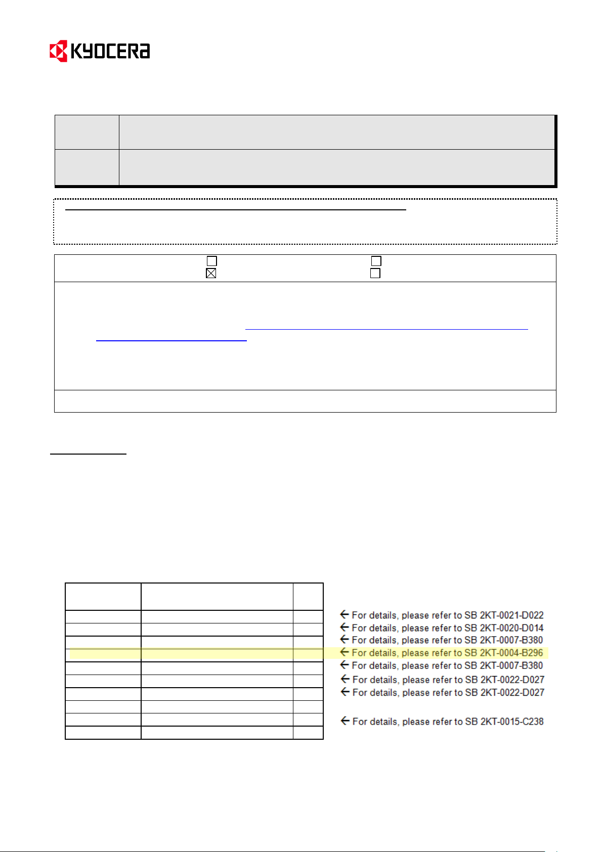
To several issues, we have created a modification kit containing the parts in the <Table.2>.
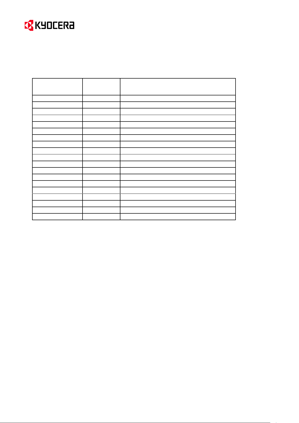
The Item code of each modification kit is described in the <Table.3>. (Each country has a different item code!)
All latest hardware updates since January are implemented in this kit.
For more details, please refer to the Service Bulletin SB-2KT-0019-D012.
We do not recommend ordering the modification kit in every case, but the price for the kit will be lower than the
parts ordered separately ,which makes the purchase more convenient.
<Table.2> Contents of the modification kit (The yellow marked part is described in this Bulletin.)
KYOCERA Document Solutions Europe
Customer Services & Support Division (CSSD)
Page 2
(Page.2/6)
Material Number
in SAP
Material
Number
in AS-400
Material Description
870LCKIT2KV1AT
GEMINI MODIFICATION KIT FOR AUSTRIA
870LCKIT2KV1BE
302KV1BE
GEMINI MODIFICATION KIT FOR BELGIUM
870LCKIT2KV1CH
302KV1CH
GEMINI MODIFICATION KIT FOR SWITZERLAND
870LCKIT2KV1DE
GEMINI MODIFICATION KIT FOR GERMANY
870LCKIT2KV1DK
GEMINI MODIFICATION KIT FOR DENMARK
870LCKIT2KV1ES
GEMINI MODIFICATION KIT FOR SPAIN
870LCKIT2KV1FI
GEMINI MODIFICATION KIT FOR FINLAND
870LCKIT2KV1FR
GEMINI MODIFICATION KIT FOR FRANCE
870LCKIT2KV1GB
GEMINI MODIFICATION KIT FOR UNITED KINGD
870LCKIT2KV1IT
GEMINI MODIFICATION KIT FOR ITALY
870LCKIT2KV1NL
302KV1NL
GEMINI MODIFICATION KIT FOR NETHERLANDS
870LCKIT2KV1NO
GEMINI MODIFICATION KIT FOR NORWAY
870LCKIT2KV1PT
302KV1PT
GEMINI MODIFICATION KIT FOR PORTUGAL
870LCKIT2KV1SE
GEMINI MODIFICATION KIT FOR SWEDEN
870LCKIT2KV1ZA
302KV1ZA
GEMINI MODIFICATION KIT FOR SOUTH AFRICA
870LCKIT2KV1RU
302KV1RU
GEMINI MODIFICATION KIT FOR RUSSIA
870LCKIT2KV100
GEMINI MODIFICATION KIT FOR INT. SALES
870LCKIT2KV130
GEMINI MODIFICATION KIT FOR OLIVETTI
870LCKIT2KV120
GEMINI MODIFICATION KIT FOR TA GmbH
Service Bulletin Ref. No. 2KV-0004 (B296)
<Table.3> Item code of the modification kit
<Date> April 23, 2013
Customer Services & Support Division (CSSD)
KYOCERA Document Solutions Europe
Page 3

(Page.3/6)
Subject
Measures against the Abnormal Image (Full-page Solid Image
or Leak Image)
A guide rib was added to the circumference of the spring contact in order to prevent the spring from running over, and
a taper was added inside the guide rib so that the spring will be correctly moved back to the regular position even if
running over.
Guide rib is added
Guide rib added
Old New
Old New
(Change for M,C,Y)
(Change for BK)
Reinforcing rib is added
Reinforcing rib added
Bending direction
Bending direction
Service Bulletin Ref. No. 2KV-0004 (B296)
<Date> April 23, 2013
Topic
Abnormal full-page solid image or leak image might appear due to contact failure of the drum high-voltage board
and the drum ground failure. Therefore, the following changes were made. (Please refer to the service bulletin SB2KV-0002-B157 “Checkpoint when the full-page solid image or leak image appears”.)
(-->) Also, the PARTS WASTE TONER ASSY SP (No.2) with the new corrective measures except the CASE
SPACER was newly registered as service part in order to enable part replacement in field. Please apply it if
necessary. (For more details and the part table, please refer to the page 3.)
1. Corrective measures for the contact failure of the drum high-voltage board
Content of Changes (-->)
<Corrective measures at production line>
A guide rib was added so that the drum ground spring will not run over the circumference of the hole.
Also, the reinforcing rib was added to prevent the guide with the hole to insert the drum ground spring from
bending.
<Field measures>
The CASE SPACER I(4 pcs. of No.1) was newly registered as service part in order to prevent the guide from
bending.
(-->) <Corrective measures at production line>
KYOCERA Document Solutions Europe
Customer Services & Support Division (CSSD)
Page 4

(Page.4/6)
Apertures where the CASE SPACERs are
attached (Field measures)
Parts to insert the drum ground spring
(Change at production line described on page 1.)
Rib
(Fig.1)
CASE SPACER (No.1)
Groove
Rib
(Fig.2)
X
CASE SPACER (No.1)
High-voltage ground spring
Guide
(To insert the drum
ground spring)
The CASE SPACER was added to press the part of inserting the drum ground
spring towards the drum ground spring side (direction of the inner machine) in order
to prevent the part of inserting the drum ground spring on the guide securing the
high-voltage ground spring from bending.
(Fig.4: Fig.2 viewed from the machine inside)
High-voltage
ground spring
Part to insert the drum
ground spring
CASE SPACER (No.1)
Direction of
pressing the guide
Aperture of the guide
Drum ground
spring
Service Bulletin Ref. No. 2KV-0004 (B296)
<Date> April 23, 2013
(-->) (Right frame viewed from inside) (Right frame viewed from outside)
<Field measures: CASE SPACER supply> (To be attached to the apertures)
Insert the T-shape part of the CASE SPACER into the aperture of the guide behind the high voltage board
aslant so that the X side of the T-shape will be first inserted (Fig.1).
Then, secure the CASE SPACER by putting the rib at the bottom into the groove of the aperture (Fig.2).
(Fig.3: Cross section of the spring contact of the drum high-voltage board)
KYOCERA Document Solutions Europe
Customer Services & Support Division (CSSD)
Page 5

(Page.5/6)
No.
Old Part
No.
New Part
No.
Description
Q’
ty
Com
bi
patility
Remarks
Old
New
Old
New
1
------------
302KV02E50
2KV02E50
CASE SPACER
-
4
-
O
*1 2 ------------
302KV94470
2KV94470
PARTS WASTE TONER ASSY SP
-
1
-
O
*2
The end of SPRING LOCK DRUM
contacts the main frame for ground.
Contact with the right side of the drum shaft
Spring end cut
[PARTS WASTE TONER ASSY SP (No.2)]
(The photo below shows the side contacting the frame.)
Parts to insert the drum ground spring
(The guide ribs and the reinforcing ribs were added.)
: <1. Corrective measures for the contact failure of the
drum high-voltage board (Change at production line)>
New drum lock spring
<2. Corrective measures for the drum ground failure >
Service Bulletin Ref. No. 2KV-0004 (B296)
<Date> April 23, 2013
2. Corrective measures for the drum ground failure
Content of changes
The shape of the drum lock spring (SPRING LOCK DRUM) was changed.
Old New
SPRING LOCK DRUM
(-->) [New service part for field measures]
Upon the request from the sales company, the assembly (No.2) for <1. Corrective measure for the contact failure of
the drum high-voltage board (Change at production line)> and <2. Corrective measures for the drum ground failure>
was newly registered as service part.
(-->)
*1: Service part for field measures (Field measure at Change 1)
*2: Service part for field measures (The assembly with the Change 1 at production line and Change 2)
KYOCERA Document Solutions Europe
Customer Services & Support Division (CSSD)
Page 6

(Page.6/6)
Model
ITEM No.
Destination
Serial Number
1102KT3NL0
KDE
Q521821161
FS-C5150DN
1102KT3UT0
UTAX/TA
Q861Y01804
1102KT3LV0
Olivetti
NHT1900473
1102KV3NL0
KDE
Q561812452
FS-C5250DN
1102KV3UT0
UTAX/TA
Q871902481
1102KV3LV0
Olivetti
NHU1900229
Model
ITEM No.
Destination
Serial Number
1102KW3NL0
KDE
From the next production
FS-C2026MFP
1102KW3UT0
UTAX/TA
From the next production
1102KW3LV0
Olivetti
From the next production
1102KX3NL0
KDE
From the next production
FS-C2126MFP
1102KX3UT0
UTAX/TA
From the next production
1102KX3LV0
Olivetti
From the next production
1102MA3NL0
KDE
NN51901613
FS-C2026MFP+
1102MA3UT0
UTAX/TA
NNW1800426
1102MA3LV0
Olivetti
NQB1Z00001
FS-C2126MFP+
1102MB3NL0
KDE
NN91804696
1102MB3UT0
UTAX/TA
NNX1801486
1102MB3LV0
Olivetti
NQC1900001
FS-C2526MFP
1102M83NL0
KDE
NML1801244
1102M83AS0
KDAU
NMK1800041
1102M83UT0
UTAX/TA
NNU1800211
1102M83LV0
Olivetti
NQ91X00046
Model
ITEM No.
Destination
Serial Number
1102M93NL0
KDE
NN11803554
FS-C2626MFP
1102M93UT0
UTAX/TA
NNV1800481
1102M93LV0
Olivetti
NQA1800058
Service Bulletin Ref. No. 2KV-0004 (B296)
<Date> April 23, 2013
(-->) Serial Nos. of the Affected Machines
KYOCERA Document Solutions Europe
Customer Services & Support Division (CSSD)
 Loading...