

Page 1
(Page 1/45)
Subject
Information on the Replacement of the Parts
(1. Measures against the Abnormal Image
2. Improvement of the Top Tray’s operability and Prevention of the Hinge
Gear Damage
3. Measures against Toner Supply Failure
4. Measures against the Display Failure of REAR COVER Opening
5. Measures against the J0501 in 250 Sheets Cassette)
Model l:
FS-C5150DN, FS-C5250DN, FS-C2026MFP, FS-C2126MFP,
FS-C2026MFP+, FS-C2126MFP+, FS-C2526MFP, FS-C2626MFP
No.
Phenomenon for which the
measures are recommended
this time
Corrective Parts
Service Bulletin
No.
Product
month of
implement
ation
Procedure
No.*
1
Measures against the
abnormal image
(Full-page solid image or
leak image)
CASE SPACER (302KV02E5_)
--- 4 pcs.
SB-2KV-0004B296
(Revised Issue
1 or later)
Nov. 2011
(A)
2
Improvement of the top tray’s
operability and prevention of
the hinge gear damage
(The hinge gear’s damage
is applied to a part of
FS-C2026MFP/C2126MFP
(Note1).)
<Improvement of the top tray’s
operability>
RATCHET SHUTTER
(302KV02501)
--- 4 pcs. (Note2)
SB-2KT-0020D014
Feb. 2013
(C)
<Prevention of the hinge gear
damage>
HINGE LID R (302KV02542)
--- 1 pc.
HINGE LID L (302KV02532)
--- 1 pc.
Sep.
2010-Dec.
2010
(B)
(E)
3
Measures against the toner
supply failure (Frequent
display of the toner
replacement message)
CAM TONER SUPPLY
(302KV02461)
--- 4 pcs.
SB-2KT-0021D022
Feb. 2013
(F)
4
Measures against the display
failure of REAR COVER
opening
LEVER INTERLOCK (302KV02521)
--- 1 pc.
SB-2KT-0015C238
July 2012Aug. 2012
(D)
5
Measures against J0501 in
250 sheets cassette
STOPPER HOOK (302KT09111)
--- 1 pc.
SPRING STOPPER HOOK
(302KT09170) --- 1 pc.
SB-2KT-0022D027
Feb. 2013
(G)
Service Bulletin Ref. No. 2KT-0019 (D012)
[Service Information] <Date> April 8, 2013
Topic
Please find the procedure how to replace the parts with the corrective parts for the following phenomena 1 to 5.
To perform other corrective measures at the same time is recommended when executing the field measure for the
phenomenon described below.
It is recommended to watch the video showing the procedure => Improvement-KIT installation procedure
(Notes) Please refer to the <table.1> below for the corrective parts and the Service Bulletin No. of the respective
phenomena.
To solve several issues, we have created a modification kit containing the parts in the <table.2>.
The Item code of each modification kit is described in the <table.3>. (Each country has a different item code!)
All latest hardware updates since January are implemented in this kit.
We do not recommend ordering the modification kit in every case, but the price for the kit will be lower than the
separate parts together which makes the purchase more convenient.
<Table.1>
KYOCERA Document Solutions Europe
Customer Services & Support Division (CSSD)
Page 2
(Page 2/45)
Item Number
Description
Qty.
302KV02461
CAM TONER SUPPLY
4
302KV02501
RATCHET SHUTTER
4
302KV02542
HINGE LID R
1
302KV02E50
CASE SPACER
4
302KV02532
HINGE LID L
1
302KT09111
STOPPER HOOK
1
302KT09170
SPRING STOPPER HOOK
1
302KV02170
GUIDE TOP L
1
302KV02521
LEVER INTERLOCK
1
302KW34040
LABEL SET ISU
1
Material Number
in SAP
Material
Number
in AS-400
Material Description
870LCKIT2KV1AT
GEMINI MODIFICATION KIT FOR AUSTRIA
870LCKIT2KV1BE
302KV1BE
GEMINI MODIFICATION KIT FOR BELGIUM
870LCKIT2KV1CH
302KV1CH
GEMINI MODIFICATION KIT FOR SWITZERLAND
870LCKIT2KV1DE
GEMINI MODIFICATION KIT FOR GERMANY
870LCKIT2KV1DK
GEMINI MODIFICATION KIT FOR DENMARK
870LCKIT2KV1ES
GEMINI MODIFICATION KIT FOR SPAIN
870LCKIT2KV1FI
GEMINI MODIFICATION KIT FOR FINLAND
870LCKIT2KV1FR
GEMINI MODIFICATION KIT FOR FRANCE
870LCKIT2KV1GB
GEMINI MODIFICATION KIT FOR UNITED KINGD
870LCKIT2KV1IT
GEMINI MODIFICATION KIT FOR ITALY
870LCKIT2KV1NL
302KV1NL
GEMINI MODIFICATION KIT FOR NETHERLANDS
870LCKIT2KV1NO
GEMINI MODIFICATION KIT FOR NORWAY
870LCKIT2KV1PT
302KV1PT
GEMINI MODIFICATION KIT FOR PORTUGAL
870LCKIT2KV1SE
GEMINI MODIFICATION KIT FOR SWEDEN
870LCKIT2KV1ZA
302KV1ZA
GEMINI MODIFICATION KIT FOR SOUTH AFRICA
870LCKIT2KV1RU
302KV1RU
GEMINI MODIFICATION KIT FOR RUSSIA
870LCKIT2KV100
GEMINI MODIFICATION KIT FOR INT. SALES
870LCKIT2KV130
GEMINI MODIFICATION KIT FOR OLIVETTI
870LCKIT2KV120
GEMINI MODIFICATION KIT FOR TA GmbH
For details, please refer to SB-2KT-0021-D022.
For details, please refer to SB-2KT-0020-D014.
For details, please refer to SB-2KT-0015-C238.
For details, please refer to SB-2KT-0022-D027.
For details, please refer to SB-2KT-0022-D027.
For details, please refer to SB-2KT-0007-B380.
For details, please refer to SB-2KT-0007-B380.
For details, please refer to SB-2KT-0004-B296.
Service Bulletin Ref. No. 2KT-0019 (D012)
[Service Information] <Date> April 8, 2013
(Note 1) The measures against the hinge gear damage have been implemented during the mass production of the FS-
C2026MFP/C2126MFP, and since the first production of other models by improving the strength due to the material change.
As for the machines without the measures, please refer to the serial number table on the next page.
However, even on the machines with the measures, “Hinge” might be bent by the stress applied by toner shutter function. If so,
it is recommended to exchange “Hinge” at the same time with modifying the other parts.
(Note 2) The HOLDER JOINT attached with the CAM TONER SUPPLY might be contaminated by toner.
When replacing the CAM TONER SUPPLY, please clean the HOLDER JOINT or replace it with the new parts (4 pcs. of
302KV0251X).
The GUIDE TOP L (302KV02170) might also have been contaminated. In this case, it is recommended to exchange this part at
the same time.
(Note 3) After the relevant parts were replaced (after the modification kit was applied), please make sure to update the firmware
to the latest version.
<Table.2> Contents of the modification kit
*” LABEL SET ISU” is just a sticker which makes the opening position of top cover in MFP model more visible.
<Table.3> Item code of the modification kit
Customer Services & Support Division (CSSD)
KYOCERA Document Solutions Europe
Page 3
(Page 3/45)
FS-C2026MFP
KDE
Olivetti
UTAX
1102KW3NL0
1102KW3LV0
1102KW3UT0
Q5A0500001to
Q5A0Z03378
N730900001 to
N730Z00250
Q880600001 to
Q880Z01276
FS-C2126MFP
KDE
Olivetti
UTAX
1102KX3NL0
1102KX3LV0
1102KX3UT0
Q5E0500001 to
Q5E0Z06121
N740900001 to
N740Z00260
Q890600001 to
Q890Z04602
Service Bulletin Ref. No. 2KT-0019 (D012)
[Service Information] <Date> April 8, 2013
[No.2: Machines with possible hinge gear damage] (Note 1 on the page 1)
*How to know the product month from serial number of machine:
For example, FS-C2026MFP S/N: Q5A0500001),
-First 3 digits ("QA5" in the example above) indicate the model code.
-Next 2 digits ("05" in the example above) indicate the product month.
("0" means year 2010, "5" means May. X=October; Y=November; Z=December)
-Next 5 digits ("00001" in the example above) are just specified numbers.
KYOCERA Document Solutions Europe
Customer Services & Support Division (CSSD)
Page 4
Service Bulletin Ref. No. 2KT-0019 (D012)
No.
Procedure
Illustration/Remarks
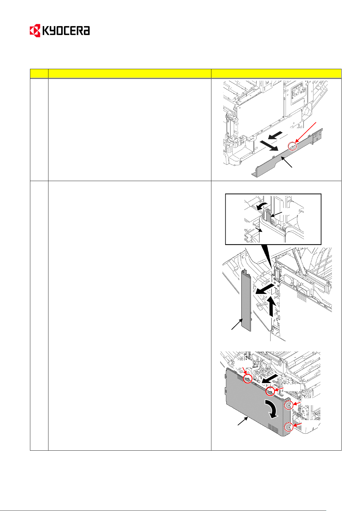
The Procedure 1 for the MFPs differs from the one for
printer models.
Go to the Procedure M1 below for the MFPs, and to
Procedure P1 for the printers.
M1
[Procedures for the MFPs]
Detach the rear upper cover, right upper cover, left upper
cover and front cover.
* These procedures are described in the Service
Manual 1-5-2 [Outer covers] (1).
(Details)
M1-1. Open the paper conveying unit.
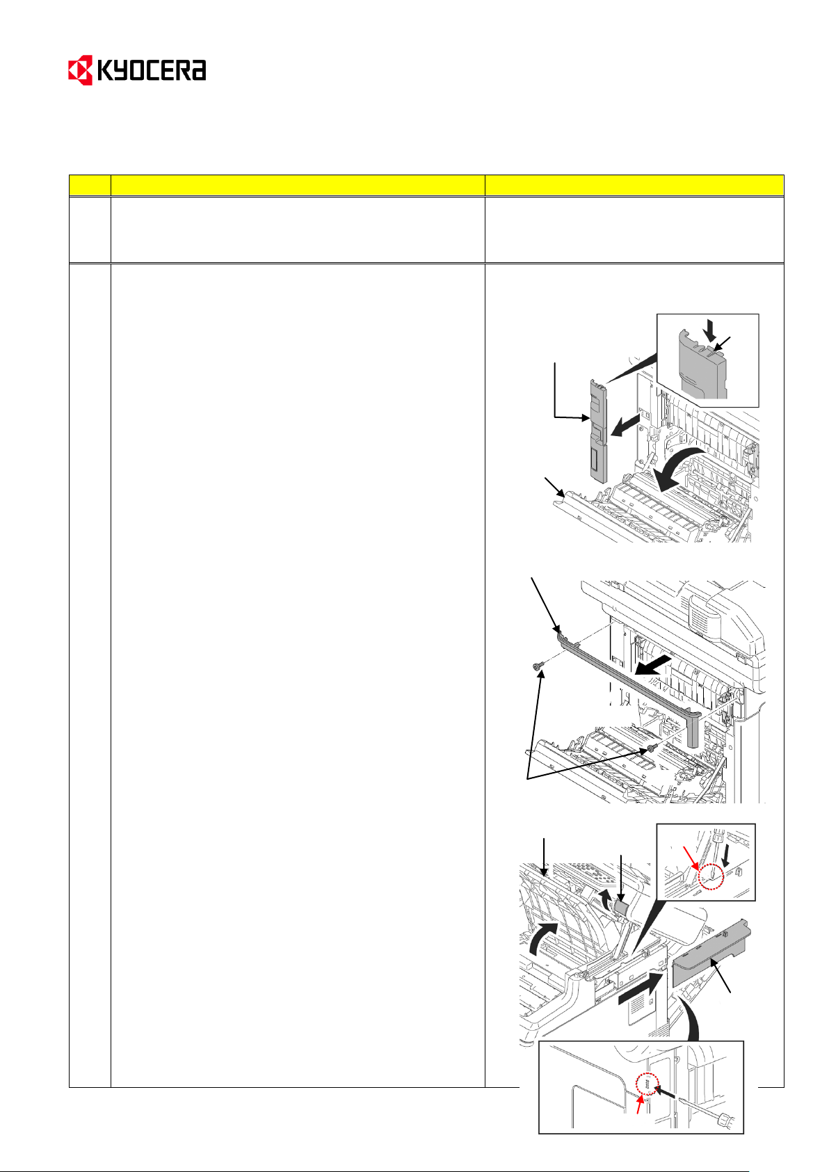
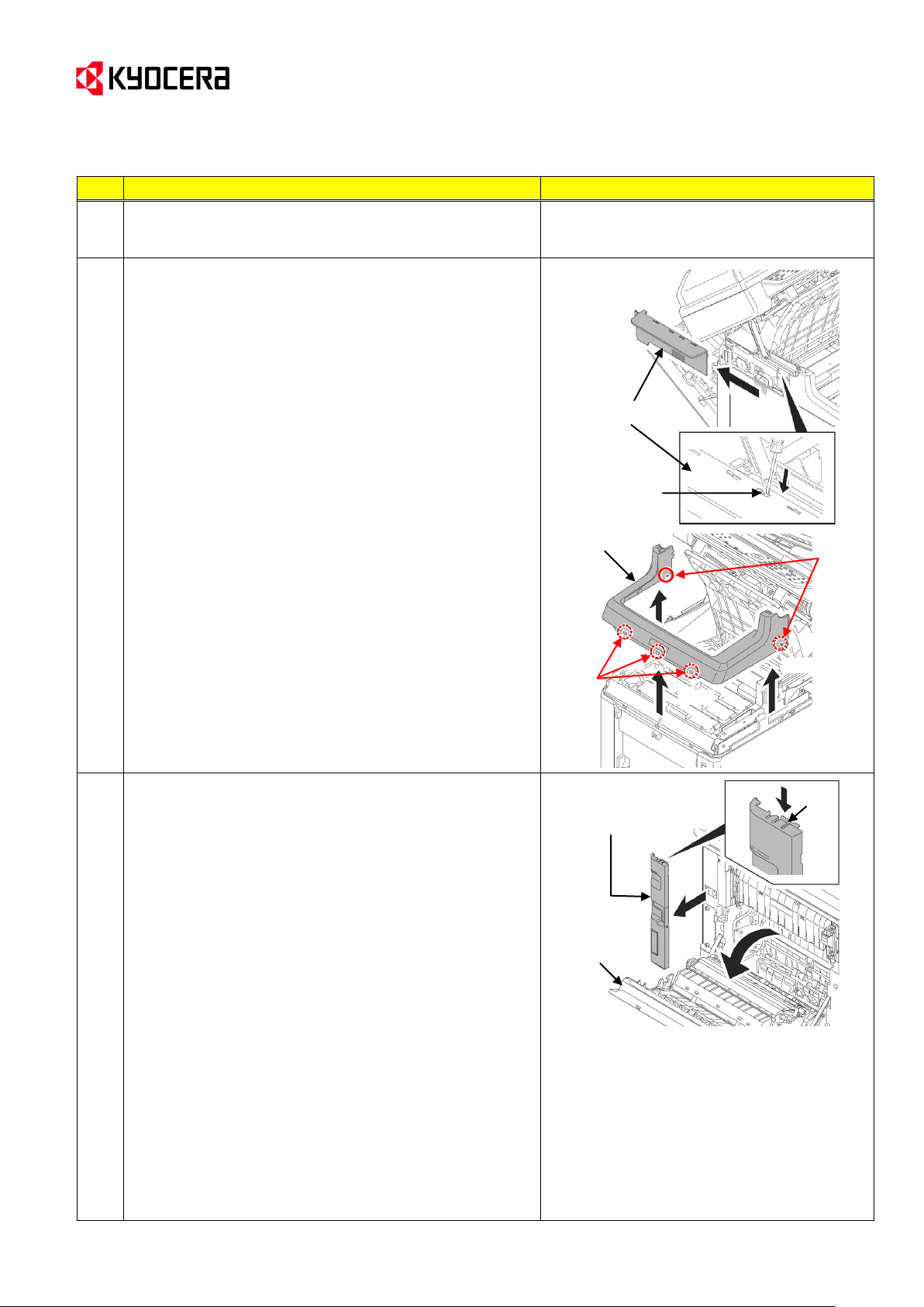
M1-2. Release the hook and then remove the IF cover.
M1-3. Remove the screw (x2). Then, remove the rear
upper cover.
M1-4. Pull the top tray lever and open the top tray.
M1-5. Release the hook (x2). Slide the right upper cover
backward and then remove it.
Hook
IF cover
Paper
conveying
unit
Screws
Rear upper cover
Right upper
cover
Top tray lever
Top tray
Hook
Hook
[Service Information] <Date> April 8, 2013
KYOCERA Document Solutions Europe
Customer Services & Support Division (CSSD)
(Page 4/45)
Page 5
(Page 5/45)
No.
Procedure
Illustration/Remarks
M1
M1-6. Release the hook. Slide the left upper cover
backward and then remove it.
M1-7. Release the hook (hook A x2; hook B x3). Then,
remove the front cover.
--> Go to Procedure 2 in page 3.
P1
[Procedure for the printers]
Detach the top cover.
* These procedures are described in the
Service Manual 1-5-2 [Outer covers] (1).
(Details)
P1-1. Open the paper conveying unit.
P1-2. Release the hook and then remove the IF cover.
Left upper cover
Hook
Front cover
Hook
B
Hook A
Hook
IF cover
Paper
conveying
unit
Service Bulletin Ref. No. 2KT-0019 (D012)
[Service Information] <Date> April 8, 2013
KYOCERA Document Solutions Europe
Customer Services & Support Division (CSSD)
Page 6
(Page 6/45)
No.
Procedure
Illustration/Remarks
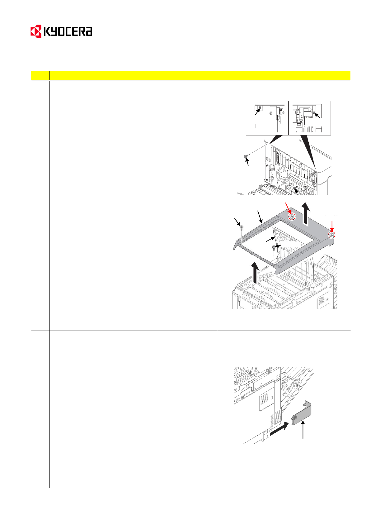
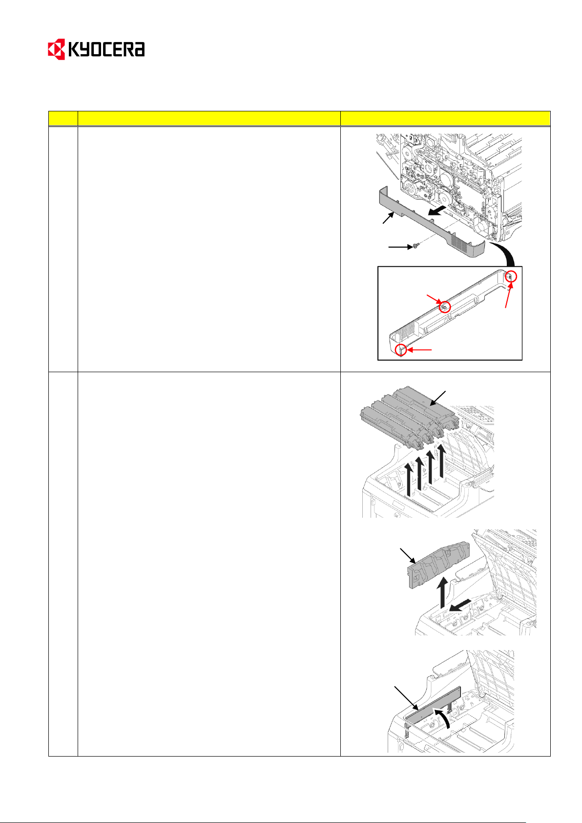
P1-3. Remove the screw (x2).
P1
P1-4. Open the top tray.
P1-5. Remove the screw (x2).
P1-6. Release the hook (x2) and then remove the top
cover.
--> Go to the following Procedure 2.
2
Detach the right rear cover, right cover and right lower
cover.
* These procedures are described in the Service
Manual 1-5-2 [Outer covers] (2).
(Details)
2-1. Slide the power source cover backward and then
remove it.
Power source cover
Screw
Screw
Screw
Screw
Screw
Top cover
Screw
Hook
Hook
Top tray
Service Bulletin Ref. No. 2KT-0019 (D012)
[Service Information] <Date> April 8, 2013
KYOCERA Document Solutions Europe
Customer Services & Support Division (CSSD)
Page 7
(Page 7/45)
No.
Procedure
Illustration/Remarks
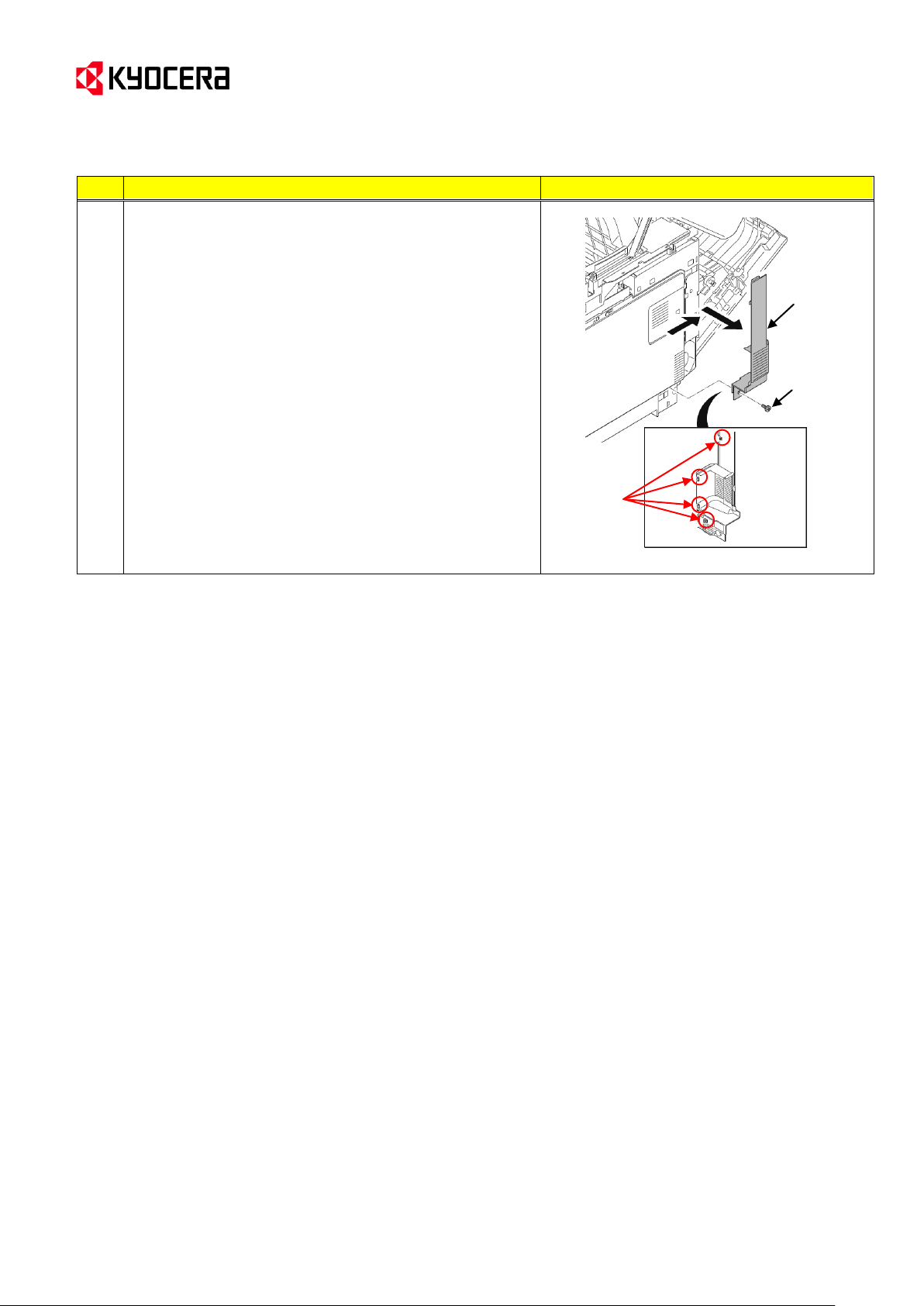
2-2. Remove the screw.
2-3. Release four hooks. Slide the right rear cover
backward and then remove it.
Right rear
cover
Screw
Hooks
Service Bulletin Ref. No. 2KT-0019 (D012)
[Service Information] <Date> April 8, 2013
Customer Services & Support Division (CSSD)
KYOCERA Document Solutions Europe
Page 8
Service Bulletin Ref. No. 2KT-0019 (D012)
No.
Procedure
Illustration/Remarks
2
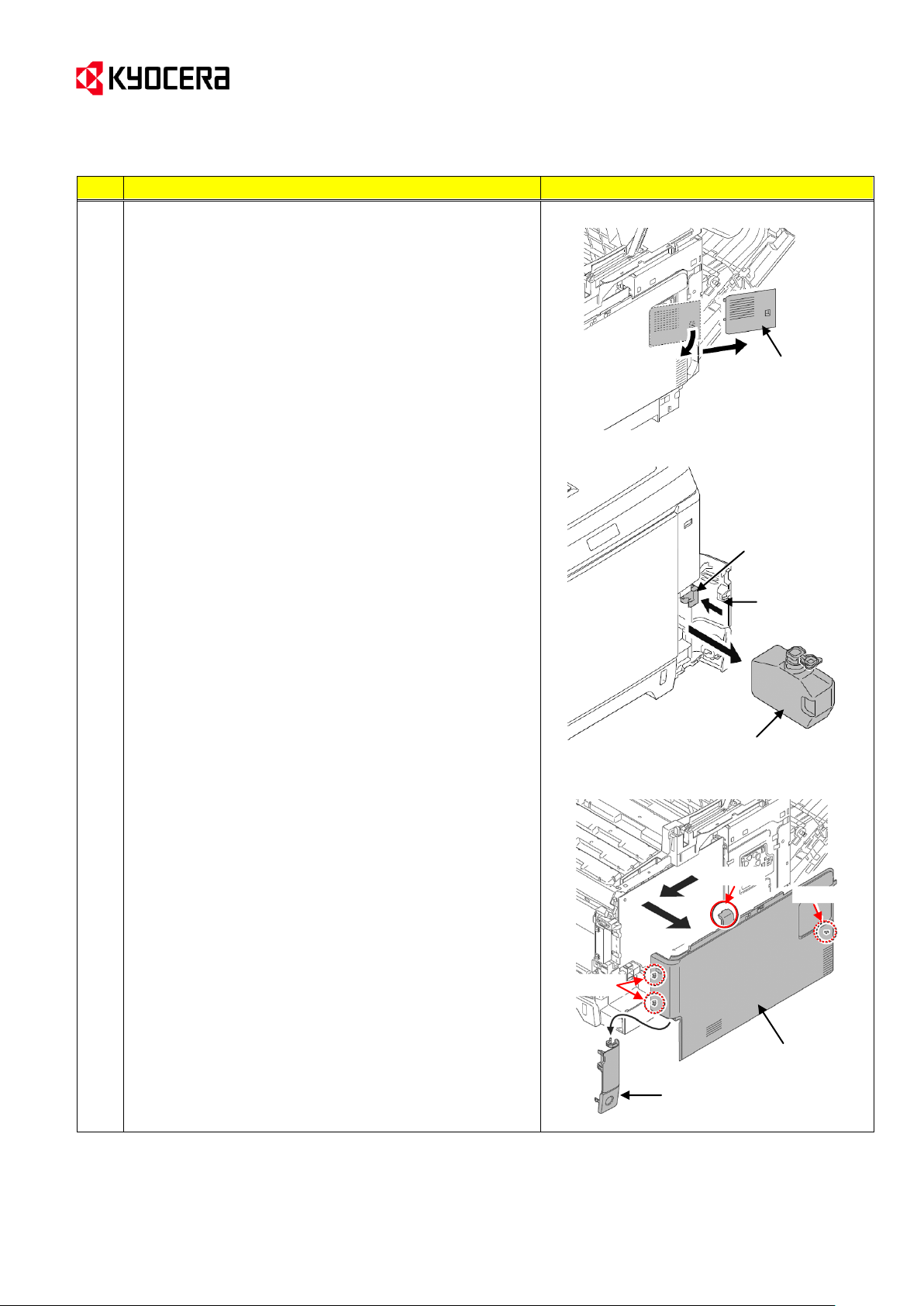
2-4. Open the memory cover and then remove it.
2-5. Open the waste toner cover.
2-6. Push the lock release button and then remove the
waste toner box.
(Close the cap of the waste toner box.)
2-7. Open the MP tray.
2-8. Release the hook (hook A x1 → B x1→ C x2).
Slide the right cover forward and then remove it.
2-9. Remove the waste toner cover.
Memory cover
Lock release button
Waste toner
cover
Waste toner box
Waste toner cover
Right cover
Hook A
Hook C
Hook B
[Service Information] <Date> April 8, 2013
KYOCERA Document Solutions Europe
Customer Services & Support Division (CSSD)
(Page 8/45)
Page 9
(Page 9/45)
No.
Procedure
Illustration/Remarks
2
2-10. Release the hook. Slide the right lower cover
forward and then remove it.
3
Detach the left rear cover, left cover and left lower cover.
* These procedures are described in the Service
Manual 1-5-2 [Outer covers] (3).
(Details)
3-1. Release the hook. Slide the left rear cover upward
and then remove it.
3-2. Release the hook A(x2) and then release the hook B
(x2) while twisting the left cover clockwise.
Then, remove the left cover.
Left rear cover
Left rear
cover
Hook
Right lower cover
Hook
Hook A
Hook B
Left cover
Hook A
Hook B
Service Bulletin Ref. No. 2KT-0019 (D012)
[Service Information] <Date> April 8, 2013
KYOCERA Document Solutions Europe
Customer Services & Support Division (CSSD)
Page 10
(Page 10/45)
No.
Procedure
Illustration/Remarks
3
3-3. Remove the screw.
3-4. Release the hook (hook A → B → C) and then
remove the left lower cover.
3-5. Close the MP tray.
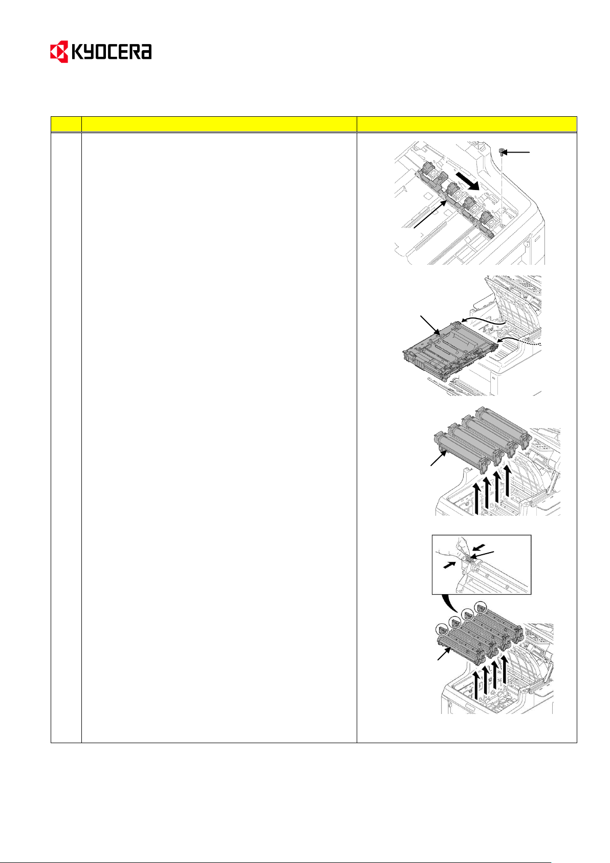
4
Detach the toner containers, the intermediate transfer units
and the drum units.
* These procedures are described in the Service
Manual 1-5-6 [(1) Detaching and refitting the
intermediate transfer unit] (3) and 1-5-5 [(1)
Detaching and refitting the drum unit].
(Details)
4-1. Remove toner containers (K, M, C, Y).
4-2. Slide the container guide forward and then remove it.
4-3. Open the RFID holder.
Toner containers
(K, M, C, Y)
RFID holder
Container guide
Left lower cover
Screw
Hook A
Hook C
Hook B
Service Bulletin Ref. No. 2KT-0019 (D012)
[Service Information] <Date> April 8, 2013
KYOCERA Document Solutions Europe
Customer Services & Support Division (CSSD)
Page 11
Service Bulletin Ref. No. 2KT-0019 (D012)
No.
Procedure
Illustration/Remarks
4
4-4. Slide the shutter forward and close the toner inlet.
4-5. Remove the screw.
4-6. Remove the intermediate transfer unit.
4-7. Remove the drum units (K, M, C, Y).
4-8. Pinch the lever of the developing unit.
4-9. Remove the developer units (K, M, C, Y)
[Note]
Please note that the machine should not be pushed
backward after removing the units from the machine
in the Procedures 4-6 to 4-9.
Shutter
Screw
Intermediate
transfer unit
Drum unit
(K, M, C, Y)
Lever
Developing unit
(K, M, C, Y)
[Service Information] <Date> April 8, 2013
KYOCERA Document Solutions Europe
Customer Services & Support Division (CSSD)
(Page 11/45)
Page 12
(Page 12/45)
No.
Procedure
Illustration/Remarks
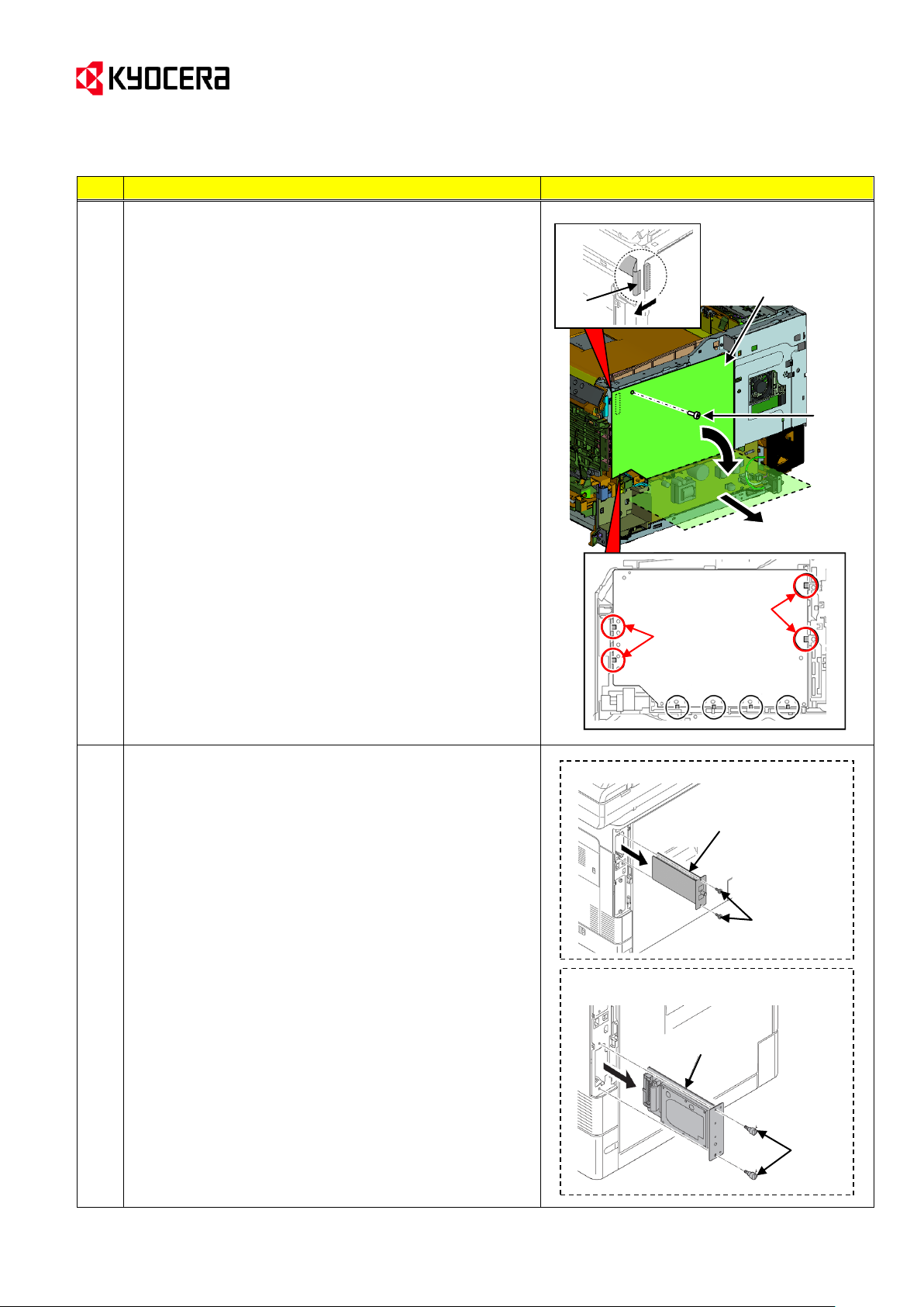
5
Detach the high voltage PWB.
(Details)
5-1. Remove the screw.
5-2. Release the hook (x4) of the upside of the PWB
circled with red in the right figure and slant the upside
of the high voltage PWB like opening it, and then
remove the FFC.
5-3. After the high voltage PWB is tilted till 90 degrees,
pull it out toward the machine right side. (Note)
(Note) If trying to pull out the PWB on the way of
slanting till 90 degrees, the hooks securing the
PWB’s low side might be damaged. (The
hooks are circled with black in the figure to the
right.)
6
Detach the main PWB.
* These procedures are described in the Service Manual 1-
5-8 [(3) Detaching and refitting the main PWB].
(Details)
<For the machine with FAX>
6-1. Remove the screw (x2) and then remove the FAX
control PWB.
<For the machine with the hard disk or the network
interface card>
6-1. Remove the pin (x2) and then pull out the hard disk or
the network interface card.
* As for the machine without FAX, go to
the Procedure 6-2.
(Machine with FAX)
Screw
FAX control PWB
HVU PWB
FFC
Hook
Hook
Screw
(Machine with the hard disk or the
network interface card)
Pin
Hard disk
Service Bulletin Ref. No. 2KT-0019 (D012)
[Service Information] <Date> April 8, 2013
KYOCERA Document Solutions Europe
Customer Services & Support Division (CSSD)
Page 13
Service Bulletin Ref. No. 2KT-0019 (D012)
No.
Procedure
Illustration/Remarks
6
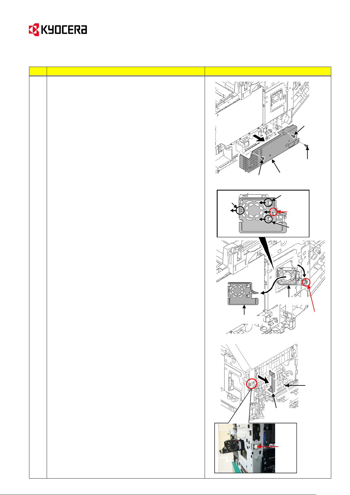
6-2. Remove the screw (x3) and then remove the power
source shield.
(Note) The screws A and B are different.
Please do not mix them up when refitting.
6-3. Pick up the hook A ant then open the fan bracket (the
bracket*).
6-4. Release the hook B and slide the fan plate (the
plate*). Release the remaining the hook (x3) and then
remove it.
* The part names in the Procedure 6-3 and 6-4 are
described as “Bracket” and “Plate” in the Service
Manual for the printer model. (The fan is not used.)
6-5. Remove the screw and then remove the fuser wire
cover.
6-6. Remove the cap.
Power source
shield
Screw A
Screw A
Screw B
Fan plate
Fan bracket
Hook
Hook
Hook
Hook B
Hook A
Fuser wire cover
Screw
Cap
[Service Information] <Date> April 8, 2013
KYOCERA Document Solutions Europe
Customer Services & Support Division (CSSD)
(Page 13/45)
Page 14
Service Bulletin Ref. No. 2KT-0019 (D012)
No.
Procedure
Illustration/Remarks
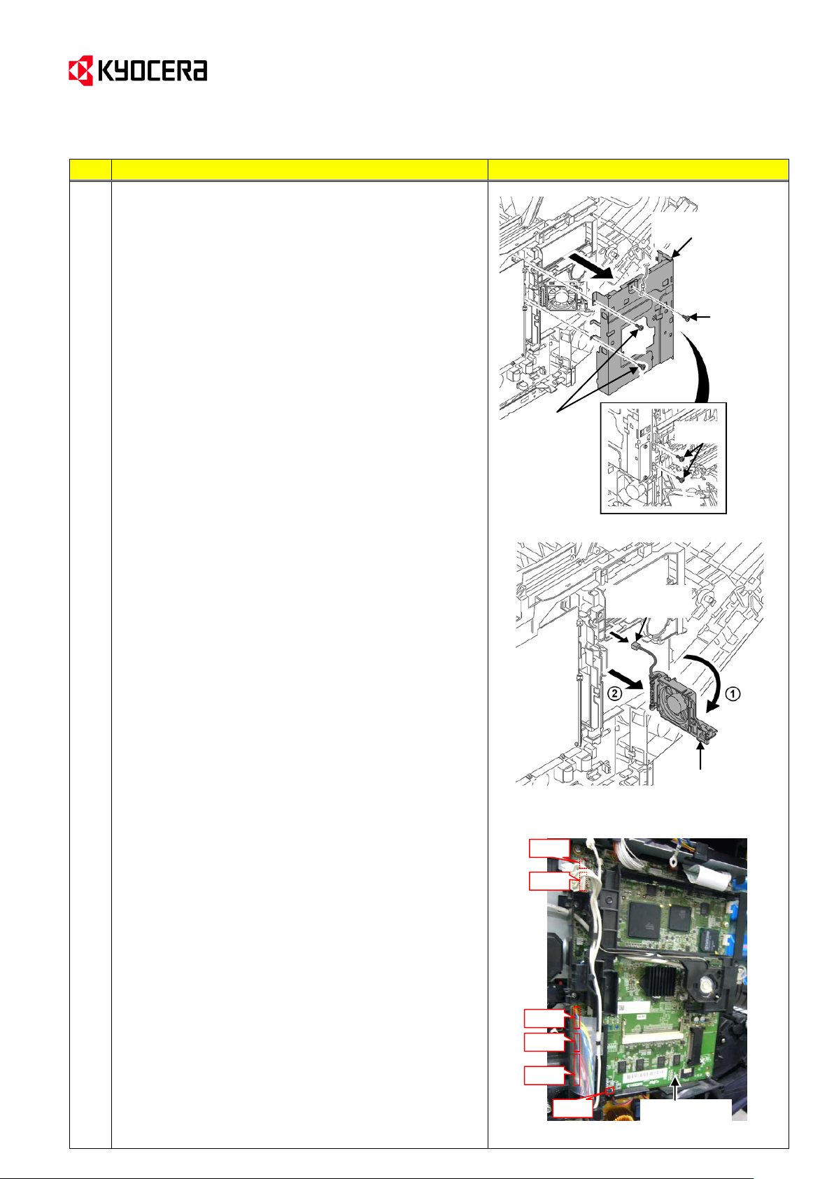
6
(For the MFP model)
6-7. Remove the screw (x5) and then remove the
controller shield.
(For the Printer model)
6-7. Remove the screw (x4) and then remove the
controller shield.
6-8. Remove the connector (YC41) of the controller fan
motor.
(The Procedure 6-8 is unnecessary for the printer
model without the fan.)
6-9. Open the fan bracket (bracket) and then remove it.
(The procedure afterwards differs between the MFPs and
printers.
For the MFP model, go to the Procedure 6-M10 below,
For the Printer model, go to Procedure 6-P10 on the page
12.)
[For the MFPs]
6-M10. Remove the connectors YC15, YC37, YC40, YC38,
YC39 and YC42 from the main PWB.
Controller shield
Screw
(MFP only)
Screw
Screw
Main PWB
YC15
YC37
YC40
YC38
YC39
YC42
Fan bracket
Connector
(YC41)
[Service Information] <Date> April 8, 2013
KYOCERA Document Solutions Europe
Customer Services & Support Division (CSSD)
(Page 14/45)
Page 15

Service Bulletin Ref. No. 2KT-0019 (D012)
No.
Procedure
Illustration/Remarks
6
6-M11. Remove the wires aligned in the wire holder.
6-M12. Remove the screw (x2).
6-M13. Release the hook (x3) and then remove the wire
holder.
6-M14. Remove the connectors YC36, YC32, YC12 and
then FFC wires YC8, YC43 from the main PWB.
(Note) Reconnect the connectors and FFC wires
above before reattaching the wire holder
which was removed in the Procedure 6M13.
6-M15. Remove the screw (x5) and then remove the main
PWB.
--> Go to the Procedure (A) on the page 13.
Main PWB
Wire holder
Screw
Hook
Screw
Screw
Main PWB
[Service Information] <Date> April 8, 2013
KYOCERA Document Solutions Europe
Customer Services & Support Division (CSSD)
(Page 15/45)
Page 16

Service Bulletin Ref. No. 2KT-0019 (D012)
No.
Procedure
Illustration/Remarks
6
[For the printers]
6-P10. Remove all connectors and FFC from the main
PWB.
6-P11. Remove the wires aligned in the wire holder.
6-P12. Remove the screw (x2) and then remove the wire
holder.
6-P13. Remove the screw (x3) and then remove the main
PWB.
--> Go to Procedure (A) in page 13.
Wire holder
Screw
Screw
Main PWB
Main PWB
Main PWB
Screw
Screw
Screw
[Service Information] <Date> April 8, 2013
KYOCERA Document Solutions Europe
Customer Services & Support Division (CSSD)
(Page 16/45)
Page 17

Service Bulletin Ref. No. 2KT-0019 (D012)
No.
Procedure
Illustration/Remarks
(A)
[Check the contact state between the drum and the
high voltage PWB] / [How to attach the CASE SPACER]
Execute the following when abnormal image (full-page solid
image or leak image) appears.
[Samples of the abnormal image]
[Check the contact state between the drum and the high
voltage PWB (Work from the machine inside)]
(A)-1.
Check if the leading edge of the drum ground springs (4
pcs.) is sufficiently inserted in the inner part of the resin
guide hole on the inner right side of the machine. (Refer
to the normal state in the photo to the right.)
If the leading edge contacts the wall around the hole like
the wrong state in the photo to the right, release its
contact using a flathead screw driver, and insert the
leading edge into the hole of the resin guide.
[Attachment of the CASE SPACER
(Work from the machine right side)]
Attach the CASE SPACER (302KV02E5_)(x4) to the
aperture of the guide behind the high voltage PWB by
following the procedures below. 連サービスブリテン No.2KV-
0004 (B296)
<CASE SPACER (302KV02E5_)>
(Inner right side of the machine)
(Machine right side)
(Leak image: Cyan and yellow
high voltage contact failure)
Drum ground spring (x4)
(Normal state)
(Wrong state)
Waste toner guide
Aperture (x4)
(Full-page solid image:
Cyan high voltage contact failure)
Leak mark
[Service Information] <Date> April 8, 2013
KYOCERA Document Solutions Europe
Customer Services & Support Division (CSSD)
(Page 17/45)
Page 18

(Page 18/45)
No.
Procedure
Illustration/Remarks
(A)
(A)-2. Insert the T-shape part of the CASE SPACER into
the aperture aslant.
(First, insert the X side of the T-shape.)
(A)-3. Attach the CASE SPACER so that the rib on the
bottom of the CASE SPACER can be inserted into
the groove of the aperture (on the upside of the
center spring).
(A)-4. Attach the CASE SPACER to the remaining section
(x3) as well.
X
Rib
[Aperture]
CASE SPACER
Groove
Service Bulletin Ref. No. 2KT-0019 (D012)
[Service Information] <Date> April 8, 2013
KYOCERA Document Solutions Europe
Customer Services & Support Division (CSSD)
Page 19

(Page 19/45)
No.
Procedure
Illustration/Remarks
7
<For MFPs only>
Detach the scanner unit with Document Processor.
(Details)
7-1. Close the RFID holder.
7-2. Remove the left and right pins by pushing the pins out
from inside while opening the top tray till the half way
of the opening angle. (After this procedure, the top
tray goes down and only the scanner unit opens.)
7-3. Release the hook (x4) and then remove the left and
right rails.
Rail
Rail
Hook
Rail
Top tray
Pin
Pin
Service Bulletin Ref. No. 2KT-0019 (D012)
[Service Information] <Date> April 8, 2013
KYOCERA Document Solutions Europe
Customer Services & Support Division (CSSD)
Page 20

Service Bulletin Ref. No. 2KT-0019 (D012)
No.
Procedure
Illustration/Remarks
7
7-4. Remove the spring (x2) from the left and right holders.
7-5. Remove the left and right holders from the scanner
unit.
(Note)
When reattaching the holders to the scanner unit,
assemble the parts so that the holders will be in
front of the triangle ribs of the ISU frame. (If the
holders are behind the triangle ribs, the scanner
unit cannot be closed.)
7-6. Release the hook (x4) and then remove the upper
middle cover.
Spring
Holder
Holder
Holder
Holder
[Attachment of the right holder]
(Normal) (Wrong)
Holder
Triangle ribs
Upper middle cover
Hook
Hook
[Service Information] <Date> April 8, 2013
KYOCERA Document Solutions Europe
Customer Services & Support Division (CSSD)
(Page 20/45)
Page 21

Service Bulletin Ref. No. 2KT-0019 (D012)
No.
Procedure
Illustration/Remarks
7
7-7. Remove the CCD wire and the LCD wire from the wire
holder 1.
Remove the screw and then remove the wire holder 2
with DP wire/Operation wires/Ground wire/Motor wire.
7-8. Remove the spring from the right side hinge and then
pull out the pins.
7-9. Remove the scanner unit with Document Processor.
(Note)
Put the scanner unit by turning it over in order to
prevent damage of the wires after detaching.
(Machine inner right side)
電線ホルダー
Scanner unit with DP
Spring
Pin
Pin
CCD wire
DP wire/Operation wires/Ground wire/
Motor wire (The wires are fixed in the wire
holder 2 by the band.)
LCD wire
Wire holder 1
Screw
Wire holder 2
[Service Information] <Date> April 8, 2013
KYOCERA Document Solutions Europe
Customer Services & Support Division (CSSD)
(Page 21/45)
Page 22

(Page 22/45)
No.
Procedure
Illustration/Remarks
8
Release each of the hooks (x4) and the claw. Then,
remove the top right cover and the top left cover.
--> For MFP model, go to the Procedure 9.
For printer model, go to the Procedure 11.
(Note)
When reattaching the top left cover and the top right cover
to MFP model, in addition to the hooks and the claw
above, attach the ribs and the hole to the ISU left and right
frames also. (The ribs and the hole are circled with red
dotted line in the figure.)
9
<For the MFPs only>
Remove the screw (x2) and then remove ISU right frame.
Remove the screw (x3) and then remove ISU left frame.
(One screw among the three screws is tightened behind
the spring.)
Top left cover
for MFP
(Top right cover for MFP) (Top right cover for Printer)
O indicate the hooks. (*) The location of each
cover is common.
Top right cover for MFP
(Top left cover for MFP) (Top left cover for Printer)
O indicate the hooks. (*) The location of each
cover is common.
Claw
Claw
Claw
Claw
Screw
Screw
ISU left frame
ISU right frame
Spring
Service Bulletin Ref. No. 2KT-0019 (D012)
[Service Information] <Date> April 8, 2013
KYOCERA Document Solutions Europe
Customer Services & Support Division (CSSD)
Page 23

(Page 23/45)
No.
Procedure
Illustration/Remarks
10
<For MFPs only>
Release the hook (x2) at the front side of the wire holder.
Also, release the wire holder by opening it from the claw
(x2) on the rear side to the arrow direction in the photo to
the right.
11
Disconnect the connector of the exit sensor wire
and then remove the wire from the aligning rib (x5) on the
top of the exit upper guide.
12
<For the MFPs>
Remove the screw (x3) and then remove the exit upper
guide.
<For the printers>
Remove the screw (x5) and then remove the exit upper
guide.
<Wire holder>
(Rear of this part)
Hook
Claw
Hook
Connector of the exit
sensor wire
Aligning ribs
Exit upper guide
(Top)
Exit upper guide
Screw
Screw
Screw
Screw for the printer model only
Service Bulletin Ref. No. 2KT-0019 (D012)
[Service Information] <Date> April 8, 2013
KYOCERA Document Solutions Europe
Customer Services & Support Division (CSSD)
Page 24

(Page 24/45)
No.
Procedure
Illustration/Remarks
13
Detach the fuser unit.
* These procedures are described in the Service
Manual 1-5-7 [(1) Detaching and refitting the fuser
unit].
(Details)
13-1. Remove the connector (x3).
13-2. Remove the screw (x2) and then remove the fuser
unit.
(Note)
Take care not to pinch the cables when refitting the fuser
unit.
14
Disconnect the connectors and the following FFC (YC23,
YC19, YC24, YC37, YC38, YC15, YC25, YC11, YC26,
YC12, YC30, YC28) from the engine PWB.
Connector
Connector
Fuser unit
Screw
Engine PWB
Engine PWB
Service Bulletin Ref. No. 2KT-0019 (D012)
[Service Information] <Date> April 8, 2013
KYOCERA Document Solutions Europe
Customer Services & Support Division (CSSD)
Page 25

(Page 25/45)
No.
Procedure
Illustration/Remarks
15
Remove the connector, screw and hook.
Remove the wire (white/black/red) from the wire aligning
ribs of the developer fan unit and then remove the
developer fan unit.
16
Remove the screw (x3), release the hook (x2). Then,
remove the fuser pressure drive unit.
(The wire of the fuser pressure drive unit is kept
connected with the toner motor holder even after
removing.)
Connector
Screw
Hook
Developer fan unit
Wire
aligning
ribs
(Rear of the developer fan unit)
Hook
Fuser pressure drive unit
Hook
Screw
Service Bulletin Ref. No. 2KT-0019 (D012)
[Service Information] <Date> April 8, 2013
KYOCERA Document Solutions Europe
Customer Services & Support Division (CSSD)
Page 26

(Page 26/45)
No.
Procedure
Illustration/Remarks
17
Release the both side fulcrum parts of the top tray by
tilting either the left or right frames outwards, and remove
the top tray forward.
(The left and right frames become movable after removing
the fuser pressure drive unit in the Procedure 16, and the
top tray can be removed without applying loads for the
fulcrum parts.)
(Note)
The shape of the fulcrum parts is same while the whole
shape of the top tray differs between the MFPs and printer
models.
18
Release the hook (x4) and then remove the exit lower
guide.
Exit lower guide
Hook
Top tray
Left and right frames
(Open to arrow direction.)
* The left and right side shapes of the
fulcrum parts of the machine/top tray are
symmetrical.
(Machine left side)
Y
X
<Fulcrum part>
X
Y
Service Bulletin Ref. No. 2KT-0019 (D012)
[Service Information] <Date> April 8, 2013
KYOCERA Document Solutions Europe
Customer Services & Support Division (CSSD)
Page 27

(Page 27/45)
No.
Procedure
Illustration/Remarks
19
Release the hook (x3) and then remove the exit lower
housing.
Hook
Exit lower housing
Service Bulletin Ref. No. 2KT-0019 (D012)
[Service Information] <Date> April 8, 2013
KYOCERA Document Solutions Europe
Customer Services & Support Division (CSSD)
Page 28

Service Bulletin Ref. No. 2KT-0019 (D012)
No.
Procedure
Illustration/Remarks
20
Detach the toner container right guide.
20-1. Remove the inner tray switch wire, the USB wire
and the FFC wire from the hook shapes of the
toner container right guide at the machine right
frame. (FFC wire is for the Printer model only.)
20-2. Disconnect the connector from the toner container
sensor.
20-3. Remove the interlock switch fixed by the claw (x2).
20-4. Release the hook (x4) on the upside using the flat-
blade screw driver, and remove the toner container
detection holder by opening it in the arrow direction
as shown in the figure.
20-5. Remove the screw fixing the toner container right
guide.
(Right frame viewed from outside)
(Right frame viewed from inside)
Toner container detection holder
Hooks on the upside
:Hooks on the HOLDERJOINT in the
HOLDER JOINT ASSY.
゙
USB wire
゙
Inner tray switch wire
FFC wire
Interlock switch
Claw
Toner container
sensor
Connector
Screw
Toner container right guide
[Service Information] <Date> April 8, 2013
KYOCERA Document Solutions Europe
Customer Services & Support Division (CSSD)
(Page 28/45)
Page 29

Service Bulletin Ref. No. 2KT-0019 (D012)
No.
Procedure
Illustration/Remarks
20
20-6. Release the hook (x5) of the toner container right
guide.
20-7. Release the hooks A and B inside of the machine by
following the procedures below.
[Note]
Take care not to damage the hooks A and B during
this release process.
1) Release the hook A (x3) from the front side while
pushing the protrusion (1) of outside of the right
frame to the inner direction.
When releasing the hook, insert a flathead screw
driver with thin leading edge lengthwise into the
inner part of the section where the hooks are
fixed and then rotate the hook A
counterclockwise (Note1) to remove it. (Fig.1)
2) While pushing the protrusion (2) to the inner
direction, insert a flathead screw driver lengthwise
into the inner part of the section where the hook B
is fixed and then rotate the hook B clockwise
(Note1) to remove it. (Fig.2)
3) Pull the LEVER INTERLOCK of the rear side of
the toner container right guide forward and
remove the toner container right guide. (Fig.3)
(Note1)
The directions of rotating the hooks A and B are the one
from inside of the machine.
If technician stands at the machine right side, the rotating
direction becomes counter direction.
Rotate the hooks A and B in the arrow direction shown in
Fig.1 and Fig.2.
(Right frame viewed from outside)
* The arrows above indicate the direction for
pushing the protrusions in the Procedure 20-7.
(Right frame viewed from inside)
Fig.2
Square hole of
the right frame
Hook B
Protrusion (1)
Protrusion (2)
Hook
Hook
Toner container right guide
Hook A
(Front)
(Back)
Hook B
Fig.1
Square hole of
the right frame
Hook A
Fig.3
LEVER INTERLOCK
Toner container right guide
[Service Information] <Date> April 8, 2013
KYOCERA Document Solutions Europe
Customer Services & Support Division (CSSD)
(Page 29/45)
Page 30

Service Bulletin Ref. No. 2KT-0019 (D012)
No.
Procedure
Illustration/Remarks
(B)
[How to replace the HINGE LID R]
If the HINGE LID R is damaged on FSC2026MFP/C2126MFP, replace the HINGE LID R with the
new one (302KV0254_: the part with material change).
※ サービ
(B)-1. Remove the HOLDER JOINT ASSY, RATCHET
SHUTTER, HOLDER JOINT ASSY, the gear (X),
the rack and HINGE LID R fitted on the toner
container right guide.
(B)-2. Reattach the new HINGE LID R with the angle of
closing the top tray. (Fully rotate the HINGE
clockwise as shown in the figure to the right.)
(B)-3. Shift the rack to the HINGE side till the hole of the
new HINGE LID R is visible from the hole of the rack.
Hook the upside of the rack on the claw (x4) of the
toner container right guide and then reattach the rack.
(The shape to push the LEVER of the rack runs over
the rib attaching the HOLDER JOINT ASSY by the
shifting work. (Fig.4) This state should be kept until
the HOLDER JOINT ASSY. is reattached.
Even if the rack runs over the rib, it does not affect
the operation since it will be released by the HINGE
rotation or the rack's sliding operation.)
(B)-4. Reattach the gear (X) when the HINGE LID is at the
angle of closing the top tray and the rack is fully
shifted to the HINGE side.
After reattaching, check if the teeth of the gear (X)
are engaged in the teeth of the HINGE and of the
rack. (Fig.5)
--> Go to the next procedure.
<Toner container right guide>
Rack
New HINGE LID R
Hole
Shift the HINGE side
Shape pushing LEVER
HOLDER JOINT ASSY
HINGE LID R
Rack
Gear (X)
RATCHET SHUTTER
Fig.4
Part where the rack runs
over the rib.
Rack
(It is translucently
indicated in the figure.)
Gear (X)
Gear (X)
HINGE LID R
Rac
Fig.5
[Service Information] <Date> April 8, 2013
KYOCERA Document Solutions Europe
Customer Services & Support Division (CSSD)
(Page 30/45)
Page 31

Service Bulletin Ref. No. 2KT-0019 (D012)
No.
Procedure
Illustration/Remarks
(C)
[How to replace the RATCHET SHUTTER]
Replace the RATCHET SHUTTER with the new one
(302KV0250: The part with 1 or later as the last digit) in
order to improve the operability when fully opening the top
tray.
<New RATCHET SHUTTER>
(C)-1. If the HOLDER JOINT of HOLDER JOINT ASSY is
contaminated by toner, clean it or replace it with the
new one (302KV0251_).
Afterwards, reassemble the HOLDER JOINT ASSY
by following the procedures below.
1) Install the spring into the center shaft of the
HOLDER JOINT.
2) Insert the JOINT into the HOLDER JOINT while
aligning the keyhole of the JOINT with the
convex part of the center shaft of the HOLDER,
and rotate the JOINT to fix it. (Fig.6)
3) Check if the flanges of the JOINT pass over
upside of the ribs of the HOLDER JOINT by
rotating JOINT. Also, check if the opening shape
at the engaging rib of the JOINT is horizontal.
<Attachment of the RATCHET and the HOLDER JOINT
ASSY.>
(C)-2. Align the notch of the new RATCHET SHUTTER to
the bending part of the toner container right guide
and then install RATCHET. Also, engage the first
tooth of the new RATCHET and the first tooth of the
rack (first tooth from the machine front side).
(Fig.7)
(C)-3. Attach the HOLDER JOINT ASSY to the section
where the new RATCHET is installed in the
Procedure (C)-2. (Insert the both claws and both
protrusions of the HOLDER JOINT ASSY into the
holes of the toner container right guide.)
(C)-4. Check if only two teeth of the rack are visible from
the backside hole. (If three teeth or more are visible,
the part should be reassembled.)
(C)-5. Repeat the procedures (C)-2 to (C)-4 for the
remaining sections (x3).
(Note)
Execute (C)-2 and (C)-3 above when pushing the rack
to the HINGE LID R side.
A distinction rib was added
to the new part.
(Fig.7)
New RATCHET SHUTTER
HOLDER JOINT ASSY
(Note)
<HOLDER JOINT ASSY>
HOLDER JOINT
(302KV0251_)
Fig.6
<HOLDER JOINT
with the spring>
<JOINT>
Keyhole shape
Convex part
Insert
Lock JOINT's
position by
rotating it.
Flange
Flanges of JOINT should pass over
upside of the rib of HOLDER.
Rack
Positioning part (RATCHET's notch and
the guide's bending part)
Rack
New
RATCHET
Engage 1st
tooth each
other.
Protrusion
Claw
Claw
Protrusion
: Opening shape
Only 2
teeth of
the rack
are
visible.
JOINT
[Service Information] <Date> April 8, 2013
KYOCERA Document Solutions Europe
Customer Services & Support Division (CSSD)
(Page 31/45)
Page 32

Service Bulletin Ref. No. 2KT-0019 (D012)
No.
Procedure
Illustration/Remarks
(D)
[How to replace the LEVER INTERLOCK]
If the message "REAR COVER OPEN" is frequently
displayed after slowly closing the top tray while the rear
cover is closed, replace the LEVER INTERLOCK with the
new one (302KV0252: 1 or later as the last digit).
<New LEVER INTERLOCK>
(D)-1. Remove the spring (Y).
(D)-2. Replace the LEVER INTERLOCK with the new one.
Hook the rib (x2) of the guide to the holes of the new
LEVER and insert the fulcrum shaft into the LEVER.
(D)-3. Hook the spring (Y) to the hook of the toner
container right guide and to the hole of the LEVER
INTERLOCK in the arrow direction as shown in the
figure to the right. (Refer to the normal and wrong
states.)
(D)-4. Check LEVER INTERLOCK can normally return
by pushing the rear edge of LEVER horizontally.
<Toner container right guide>
Distinction rib added to the
new LEVER
LEVER INTERLOCK
Spring (Y)
Rib
Fulcrum shaft
Rib
LEVER INTERLOCK
(Normal state) (Wrong state)
Spring (Y)
The spring should
not run over the
corner of the
guide.
[Service Information] <Date> April 8, 2013
KYOCERA Document Solutions Europe
Customer Services & Support Division (CSSD)
(Page 32/45)
Page 33

Service Bulletin Ref. No. 2KT-0019 (D012)
No.
Procedure
Illustration/Remarks
21
Reattach the toner container right guide to the machine.
Then, reconnect and realign the connectors and the wires
that were removed in the Procedure 20-1 to 20-4.
Also, reattach the toner container detection holder.
After reattaching, check the following points.
1) Check if the HINGE LID R is at the same angle as the
one for closing the top tray.
(The rib of the HINGE LID R should not be higher than
the upside of the toner container right guide. Please
refer to the figure to the right.)
2) Check if two teeth of the rack are visible from every
JOINT section.
3) Check if the opening shape at the engaging rib of the
JOINT is horizontal as shown in the figure to the right.
HINGE LID R
Toner container
right guide
Correct Wrong
HINGE's rib
Upside of the toner container right guide
2 teeth of
the rack
JOINT
: Opening shape
<Angle of the opening shape>
(Other than 5150DN)
(Correct) (Wrong)
<Angle of the opening shape>
(5150DN only)
(Correct) (Wrong)
[Service Information] <Date> April 8, 2013
KYOCERA Document Solutions Europe
Customer Services & Support Division (CSSD)
(Page 33/45)
Page 34

(Page 34/45)
No.
Procedure
Illustration/Remarks
21
4) Check if the actuator to switch the toner container
sensor contacts the front side of the toner container
detection holder after the toner container detection
holder with the hook (x8) was reattached.
(Right frame viewed from outside)
(Front side)
Toner container detection holder
The parts should contact.
Actuator to switch the toner container
sensor
Service Bulletin Ref. No. 2KT-0019 (D012)
[Service Information] <Date> April 8, 2013
KYOCERA Document Solutions Europe
Customer Services & Support Division (CSSD)
Page 35

(Page 35/45)
No.
Procedure
Illustration/Remarks
22
Detach the toner motor holder from the machine left side.
22-1. Remove the duplex motor wire connected to the
connector YC37 on the engine PWB from the
aligning ribs of the low side of the toner motor
holder.
22-2. Remove the FFC wire connected to the connector
YC12 on the engine PWB from the aligning rib of
the front side of the toner motor holder.
22-3. Remove the screw fixing the front side of the toner
motor holder.
(Left frame viewed from the machine left side)
Duplex motor
Toner motor holder
Aligning ribs
Screw
Aligning
rib
FFC wire
Service Bulletin Ref. No. 2KT-0019 (D012)
[Service Information] <Date> April 8, 2013
KYOCERA Document Solutions Europe
Customer Services & Support Division (CSSD)
Page 36

Service Bulletin Ref. No. 2KT-0019 (D012)
No.
Procedure
Illustration/Remarks
22
22-4. Disconnect the connector from the PWB of the
intermediate transfer drive unit and remove the
screw fixing the toner motor holder.
22-5. Release the hook (x6).
22-6. Open the toner motor holder to the machine left side
and then remove the ID sensor holder from inside
the toner motor holder.
22-7. Remove the toner motor holder.
22-8. Clean the jointing hole (x4) with dry cloth from the
machine left side.
Screw
Connector
Intermediate transfer drive unit
Toner motor holder
Toner motor holder
O indicates 6 hooks.
ID sensor holder
Jointing holes
[Service Information] <Date> April 8, 2013
KYOCERA Document Solutions Europe
Customer Services & Support Division (CSSD)
(Page 36/45)
Page 37

Service Bulletin Ref. No. 2KT-0019 (D012)
No.
Procedure
Illustration/Remarks
(E)
[How to replace the HINGE LID L]
Replace the HINGE LID L with the new one (302KV0253_:
the parts changing its material) by following the
procedures below if the HINGE of FSC2026MFP/C2126MFP is damaged.
(市場供給品は全て新材料品)
(E)-1. Remove the screw and release the hook (x9).
Then, remove the toner container left guide from
the left frame.
(E)-2. Remove the old left hinge gear and the gear (X)
from the toner container left guide.
(E)-3. Install the new left hinge gear at the angle for
closing the top tray. (It contacts the rib of the toner
container left guide at the state of the right figure.)
(E)-4. Slide the rack at the toner container left guide
backward (the left hinge gear side).
(E)-5. Rotate the gear (Y) clockwise by one tooth.
* Confirm that there is space of approx. 3 mm
between the rib of the guide and the claw of the
rack lower part.
(E)-6. Refit the gear (X).
(E)-7. Refit the toner container left guide to the left frame.
O indicates 9 hooks.
HINGE LID L
Gear (X)
Gear (Y)
About 3mm
Rack
Screw
Toner container left guide
HINGE LID L
[Service Information] <Date> April 8, 2013
KYOCERA Document Solutions Europe
Customer Services & Support Division (CSSD)
(Page 37/45)
Page 38

(Page 38/45)
No.
Procedure
Illustration/Remarks
(E)
(E)-8. Check if the rib edge of the rack is invisible from
the aperture of the left frame after reassembling.
(If it is visible, the angle of the HINGE LID L is not
same as the state when closing the top tray. In
this case, reassemble the parts after checking the
toner container left guide.)
Left frame
(Normal) (Wrong)
<Rack>
Rib edge
Service Bulletin Ref. No. 2KT-0019 (D012)
[Service Information] <Date> April 8, 2013
KYOCERA Document Solutions Europe
Customer Services & Support Division (CSSD)
Page 39

(Page 39/45)
<Joint part>
CAM
Groove
Groove
No.
Procedure
Illustration/Remarks
(F)
[How to replace the CAM TONER SUPPLY]
When the toner can be supplied and the message for
instructing the toner replacement frequently appears due
to the engaging failure between the toner motor joint at the
machine left side and the joint gear of the toner container,
replace 4 pcs of CAM TONER SUPPLY with the new parts
(302KV0246: 1 or later of the last digit parts number) by
the following procedures.
(F)-1. Remove 4 pcs. of the old CAM TONER SUPPLY
from the toner motor holder.
(F)-2. Attach the new CAM TONER SUPLY on the toner
motor joint by inserting the claw (x2) into the
grooves of the guide.
(F)-3. Check if the toner motor joint does not idle by
rotating. (At that time, the convex part of CAM faces
the lower right direction.)
(F)-4. Reattach the toner motor holder by tightening the
screw (x2) and hooking the hook (x6).
<Toner motor holder>
(Left frame side)
(View from backside)
[Attachment]
CAM TONER SUPPLY
Claw
Claw
Claw
Claw
CAM's convex part
(Normal state is in the
photo on the next
page.)
Toner motor joint
(Different shape
according to the
model and spec)
<New CAM TONER SUPPLY>
The edge of the new
part is cut for
distinction.
Service Bulletin Ref. No. 2KT-0019 (D012)
[Service Information] <Date> April 8, 2013
KYOCERA Document Solutions Europe
Customer Services & Support Division (CSSD)
Page 40

Service Bulletin Ref. No. 2KT-0019 (D012)
No.
Procedure
Illustration/Remarks
(F)
[Note]
Check the following points when refitting the toner motor
holder.
1) Check all convex parts of the cam at the toner motor
joint face the lower right at the angle of the HINGE LID
L at the state of closing the top tray. (Please refer to
the figure.)
2) Check if all hooks (x6) of the toner motor holder are
surely hooked the left frame.
(Note)
If the hook is insufficiently hooked, toner supply failure
might occur.
3) Check if the film (x2) affixed at the upside of the
engine PWB are not pinched between the toner motor
holder and the left frame.
2 films
Engine PWB
Toner motor holder
O indicates hooks.
Toner motor holder
Convex part of
CAM at the toner motor joint
HINGE LID L
(Angle when the top tray
is closed.)
Normal
Wrong
[Service Information] <Date> April 8, 2013
KYOCERA Document Solutions Europe
Customer Services & Support Division (CSSD)
(Page 40/45)
Page 41

(Page 41/45)
No.
Procedure
Illustration/Remarks
(F)
4) Check if the film to clean the ID sensor installed inside
of the toner motor holder does not twist at the aligning
rib. Then, slide the switch of the ID sensor back and
forth to see if it be can be normally slid.
23
Reassemble all parts and the unit detached in the reverse
order of the disassembly.
24
After reassembling, affix the LABEL SET ISU to the right
holder of the scanner unit if necessary.
<LABEL SET ISU (302KW3404_)>
* This is the label to clearly indicate the scanner unit's
lock position when the top tray is fully opened.
(The lock position is where the corner of the triangle
shape of the right holder comes to the engraving on
the right upper cover.)
<Procedures>
1) Open the top tray.
2) Clean the triangle shape of the fulcrum part of the
scanner unit's right holder with alcohol.
3) Affix the LABEL SET ISU according to the alignments
shown in the figure.
[Alignments]
Engraving to
indicate the
lock position
when opening
the top tray
Right holder
Align to the rib
Rib
Align to the edge of the holder
0.5mm
0.5mm
LABEL SET ISU
(302KW3404_)
ID guide
Switch of the ID sensor
Film to clean ID
sensor
Service Bulletin Ref. No. 2KT-0019 (D012)
[Service Information] <Date> April 8, 2013
KYOCERA Document Solutions Europe
Customer Services & Support Division (CSSD)
Page 42

(Page 42/45)
No.
Procedure
Illustration /Remark
1
Remove the cassette.
2
Release the hook (x4) indicated by the
triangle engravings and remove the cover
from the cassette right rear side.
3
Release the hook (x2) and remove the
bottom plate from the side of the hooks.
Cassette
250-sheets cassette
Hook
Cover
Bottom plate
Hook
Service Bulletin Ref. No. 2KT-0019 (D012)
[Service Information] <Date> April 8, 2013
G: [How to attach the new STOPPER HOOK and the SPRING STOPPER HOOK only for the machine with
250 sheets cassette]
KYOCERA Document Solutions Europe
Customer Services & Support Division (CSSD)
Page 43

(Page 43/45)
No.
Procedure
Illustration /Remark
4
Lift up the center hook using a flathead
screwdriver and remove the stop ring in
the direction of the arrow as shown in the
figure.
5
Pull out the shaft and remove the old
STOPPER HOOK.
250-sheets cassette
<Stop ring>
Lift up the center hook
Shaft
(Cassette rear side)
Old STOPPER HOOK
Service Bulletin Ref. No. 2KT-0019 (D012)
[Service Information] <Date> April 8, 2013
KYOCERA Document Solutions Europe
Customer Services & Support Division (CSSD)
Page 44

(Page 44/45)
No.
Procedure
Illustration /Remark
6
Attach the SPRING STOPPER HOOK
(No.4) to the new STOPPER HOOK
(No.3). At that time, put the edge of the
SPRING (hooking shape) on the bottom
side of the new STOPPER.
<New STOPPER HOOK ASSY>
7
Attach the new STOPPER HOOK ASSY
to the cassette rear side.
At that time, put the edge of the SPRING
on the cassette’s base.
8
Reinsert the shaft removed in the Step 5
and fix the new STOPPER HOOK ASSY.
Note the following points when reinserting
the shaft.
1) Confirm that the gear attached to the
shaft’s right edge is engaged with the
bottom plate drive gear.
(Backside of the left figure:
Bottom)
SPRING STOPPER HOOK (No.4)
Put the edge of the SPRING.
New STOPPER HOOK
(No.3)
New STOPPER HOOK ASSY
Put the edge of the SPRING on the base.
Gear Bottom plate drive gear
Service Bulletin Ref. No. 2KT-0019 (D012)
[Service Information] <Date> April 8, 2013
KYOCERA Document Solutions Europe
Customer Services & Support Division (CSSD)
Page 45

(Page 45/45)
No.
Procedure
Illustration /Remark
8
2) Pass the shaft over the ground spring.
3) Reinsert the shaft’s left end (oval
shape) into the plate’s square hole
while aligning it to its directions.
9
Reassemble other parts in the reverse
order of disassembly.
Ground spring
Shaft
New STOPPER HOOK ASSY
Plate square hole
(It is located sideward.)
<Shaft>
Left end (Oval shape)
Service Bulletin Ref. No. 2KT-0019 (D012)
[Service Information] <Date> April 8, 2013
KYOCERA Document Solutions Europe
Customer Services & Support Division (CSSD)
 Loading...