

Kyocera DF-73 Service Manual

DF-73
SERVICE
MANUAL
Published in Sep. ’03
845HL110

CAUTION
Danger of explosion if battery is incorrectly replaced. Replace only with the same or equivalent
type recommended by the manufacturer. Dispose of used batteries according to the
manufacturer’s instructions.
CAUTION
Double-pole/neutral fusing.

Safety precautions
This booklet provides safety warnings and precautions for our service personnel to ensure the safety of
their customers, their machines as well as themselves during maintenance activities. Service personnel
are advised to read this booklet carefully to familiarize themselves with the warnings and precautions
described here before engaging in maintenance activities.

Safety warnings and precautions
Various symbols are used to protect our service personnel and customers from physical danger and
to prevent damage to their property. These symbols are described below:
DANGER: High risk of serious bodily injury or death may result from insufficient attention to or incorrect
compliance with warning messages using this symbol.
WARNING:Serious bodily injury or death may result from insufficient attention to or incorrect compliance
with warning messages using this symbol.
CAUTION:Bodily injury or damage to property may result from insufficient attention to or incorrect
compliance with warning messages using this symbol.
Symbols
The triangle ( ) symbol indicates a warning including danger and caution. The specific point
of attention is shown inside the symbol.
General warning.
Warning of risk of electric shock.
Warning of high temperature.
indicates a prohibited action. The specific prohibition is shown inside the symbol.
General prohibited action.
Disassembly prohibited.
indicates that action is required. The specific action required is shown inside the symbol.
General action required.
Remove the power plug from the wall outlet.
Always ground the copier.
1. Installation Precautions
WARNING
• Do not use a power supply with a voltage other than that specified. Avoid multiple connections to
one outlet: they may cause fire or electric shock. When using an extension cable, always check
that it is adequate for the rated current. ............................................................................................
• Connect the ground wire to a suitable grounding point. Not grounding the copier may cause fire or
electric shock. Connecting the earth wire to an object not approved for the purpose may cause
explosion or electric shock. Never connect the ground cable to any of the following: gas pipes,
lightning rods, ground cables for telephone lines and water pipes or faucets not approved by the
proper authorities. .............................................................................................................................
CAUTION:
• Do not place the copier on an infirm or angled surface: the copier may tip over, causing injury. .....
• Do not install the copier in a humid or dusty place. This may cause fire or electric shock. ..............
• Do not install the copier near a radiator, heater, other heat source or near flammable material.
This may cause fire. ..........................................................................................................................
• Allow sufficient space around the copier to allow the ventilation grills to keep the machine as cool
as possible. Insufficient ventilation may cause heat buildup and poor copying performance. ..........
• Always handle the machine by the correct locations when moving it. ..............................................
• Always use anti-toppling and locking devices on copiers so equipped. Failure to do this may
cause the copier to move unexpectedly or topple, leading to injury..................................................
• Avoid inhaling toner or developer excessively. Protect the eyes. If toner or developer is
accidentally ingested, drink a lot of water to dilute it in the stomach and obtain medical attention
immediately. If it gets into the eyes, rinse immediately with copious amounts of water and obtain
medical attention. ..............................................................................................................................
• Advice customers that they must always follow the safety warnings and precautions in the copier’s
instruction handbook. ........................................................................................................................

2. Precautions for Maintenance
WARNING
• Always remove the power plug from the wall outlet before starting machine disassembly...............
• Always follow the procedures for maintenance described in the service manual and other related
brochures. .........................................................................................................................................
• Under no circumstances attempt to bypass or disable safety features including safety
mechanisms and protective circuits. .................................................................................................
• Always use parts having the correct specifications...........................................................................
• Always use the thermostat or thermal fuse specified in the service manual or other related
brochure when replacing them. Using a piece of wire, for example, could lead to fire or other
serious accident. ...............................................................................................................................
• When the service manual or other serious brochure specifies a distance or gap for installation of a
part, always use the correct scale and measure carefully. ...............................................................
• Always check that the copier is correctly connected to an outlet with a ground connection. ............
• Check that the power cable covering is free of damage. Check that the power plug is dust-free. If
it is dirty, clean it to remove the risk of fire or electric shock. ............................................................
• Never attempt to disassemble the optical unit in machines using lasers. Leaking laser light may
damage eyesight. ..............................................................................................................................
• Handle the charger sections with care. They are charged to high potentials and may cause
electric shock if handled improperly. .................................................................................................
CAUTION
• Wear safe clothing. If wearing loose clothing or accessories such as ties, make sure they are
safely secured so they will not be caught in rotating sections...........................................................
• Use utmost caution when working on a powered machine. Keep away from chains and belts. .......
• Handle the fixing section with care to avoid burns as it can be extremely hot. .................................
• Check that the fixing unit thermistor, heat and press rollers are clean. Dirt on them can cause
abnormally high temperatures...........................................................................................................
• Do not remove the ozone filter, if any, from the copier except for routine replacement....................

• Do not pull on the AC power cord or connector wires on high-voltage components when removing
them; always hold the plug itself. ......................................................................................................
• Do not route the power cable where it may be stood on or trapped. If necessary, protect it with a
cable cover or other appropriate item. ..............................................................................................
• Treat the ends of the wire carefully when installing a new charger wire to avoid electric leaks........
• Remove toner completely from electronic components. ...................................................................
• Run wire harnesses carefully so that wires will not be trapped or damaged. ...................................
• After maintenance, always check that all the parts, screws, connectors and wires that were
removed, have been refitted correctly. Special attention should be paid to any forgotten
connector, trapped wire and missing screws. ..................................................................................
• Check that all the caution labels that should be present on the machine according to the
instruction handbook are clean and not peeling. Replace with new ones if necessary. ...................
• Handle greases and solvents with care by following the instructions below: ....................................
· Use only a small amount of solvent at a time, being careful not to spill. Wipe spills off completely.
· Ventilate the room well while using grease or solvents.
· Allow applied solvents to evaporate completely before refitting the covers or turning the main
switch on.
· Always wash hands afterwards.
• Never dispose of toner or toner bottles in fire. Toner may cause sparks when exposed directly to
fire in a furnace, etc...........................................................................................................................
• Should smoke be seen coming from the copier, remove the power plug from the wall outlet
immediately. ......................................................................................................................................
3. Miscellaneous
WARNING
• Never attempt to heat the drum or expose it to any organic solvents such as alcohol, other than
the specified refiner; it may generate toxic gas. ................................................................................

CONTENTS
1-1 Specifications
1-1-1 Specifications ....................................................................................................................................... 1-1-1
1-1-2 Parts names ......................................................................................................................................... 1-1-2
1-1-3 Machine cross section .......................................................................................................................... 1-1-3
1-1-4 Drive system ........................................................................................................................................ 1-1-4
(1) Drive system 1 (machine front side) ............................................................................................... 1-1-4
(2) Drive system 2 (machine rear side) ................................................................................................ 1-1-4
1-2 Installation
1-2-1 Unpacking and installation ................................................................................................................... 1-2-1
(1) Unpacking ....................................................................................................................................... 1-2-1
(2) Remove the tapes and pad ............................................................................................................ 1-2-2
1-3 Troubleshooting
1-3-1 Paper misfeed detection ...................................................................................................................... 1-3-1
(1) Paper misfeed indication ................................................................................................................ 1-3-1
(2) Paper misfeed detection conditions ................................................................................................ 1-3-1
(3) Paper misfeeds ............................................................................................................................... 1-3-3
1-3-2 Self-diagnosis ....................................................................................................................................... 1-3-6
(1) Self-diagnostic function .................................................................................................................. 1-3-6
(2) Self-diagnostic codes ..................................................................................................................... 1-3-6
1-3-3 Electrical problems ............................................................................................................................... 1-3-8
(1) The reverse motor does not operate. ............................................................................................. 1-3-8
(2) The paper conveying motor does not operate. ............................................................................... 1-3-8
(3) The adjustment motor does not operate. ........................................................................................ 1-3-8
(4) The tary elevation motor does not operate. .................................................................................... 1-3-8
(5) The separate solenoid does not operate. ....................................................................................... 1-3-8
(6) The flapper solenoid does not operate. .......................................................................................... 1-3-8
(7) The large gear solenoid does not operate. ..................................................................................... 1-3-9
(8) The paddle solenoid does not operate. .......................................................................................... 1-3-9
(9) The surface view solenoid does not operate. ................................................................................. 1-3-9
(10) Paper jams when the power switch is turned on. ........................................................................... 1-3-9
(11) “Out of staples. Add staples.” is displayed when the power switch is turned on. ......................... 1-3-10
1-3-4 Mechanical problems ......................................................................................................................... 1-3-11
(1) No paper conveying. ..................................................................................................................... 1-3-11
(2) No paper ejection to the exit tray. ................................................................................................. 1-3-11
(3) Paper jams. .................................................................................................................................. 1-3-11
(4) Abnormal noise is heard. .............................................................................................................. 1-3-11
5HL
1-4 Assembly and Disassembly
1-4-1 Assembly and disassembly .................................................................................................................. 1-4-1
(1) Precautions ..................................................................................................................................... 1-4-1
(2) Cleaning the paper conveying roller and reverse exit roller ........................................................... 1-4-2
2-1 Mechanical construction
2-1-1 Mechanical construction ....................................................................................................................... 2-1-1
(1) Reverse section .............................................................................................................................. 2-1-1
(2) Processing section ......................................................................................................................... 2-1-8
(3) Exit tray section ............................................................................................................................ 2-1-13
1-1-1

5HL
2-2 Electrical Parts Layout
2-2-1 Electrical parts layout ........................................................................................................................... 2-2-1
(1) PCB ................................................................................................................................................ 2-2-1
(2) Switches and sensors ..................................................................................................................... 2-2-2
(3) Motors ............................................................................................................................................. 2-2-3
(4) Solenoids ........................................................................................................................................ 2-2-4
(5) Stapler section ................................................................................................................................ 2-2-5
2-3 Operation of the PCB
2-3-1 Main PCB ............................................................................................................................................. 2-3-1
2-4 Appendixes
Timing chart No. 1 .......................................................................................................................................... 2-4-1
Timing chart No. 2 .......................................................................................................................................... 2-4-2
Timing chart No. 3 .......................................................................................................................................... 2-4-3
Periodic maintenance procedure .................................................................................................................... 2-4-4
List of maintenance parts ............................................................................................................................... 2-4-4
Wring diagram ................................................................................................................................................ 2-4-5
1-1-2

1-1-1 Specifications
Type ............................................... Floor model
Number of trays.............................. One tray
Tray capacity .................................. When not stapling:
A3, B4 (257 mm × 364 mm), 11" × 17" or 8
A4R, A4, 8
*A4R and 8
(For B5R, job offset is not available.)
When stapling 2 or 9 sheets:
A3, B4 (257 mm × 364 mm), 11" × 17" or 8
A4R, A4, B5, 8
When stapling 10 or 20 sheets:
A3, B4 (257 mm × 364 mm), 11" × 17" or 81/2" × 14": 25 to 12 sets
A4R, A4, B5, 8
When stapling 21 or 30 sheets:
A4R, A4, B5, 81/2" × 11" or 11" × 81/2": 45 to 16 sets
Stapling limit ................................... A3, B4 (257 mm × 364 mm), Folio, 11" × 17" or 8
A4R, A4, 8
Power source ................................. Electrically connected to the copier
Dimensions .................................... 558 (W) × 526 (D) × 916 (H) mm
22" (W) × 20
Weight ............................................Approx. 25 kg/55 lbs (with attachments)
1
/2" × 11" or 11" × 81/2": 1000 sheets*
1
/2" × 11" during sorting or offset ejection: 500 sheets
1
/2" × 11" or 11" × 81/2": 70 to 50 sets
1
/2" × 11" or 11" × 81/2": 45 to 16 sets
1
/2" × 11" or 11" × 81/2": 30 sheets
11
/16" (D) × 361/16" (H)
1
/2" × 14": 500 sheets
1
/2" × 14": 70 to 28 sets
1
/2" × 14": 20 sheets
5HL
1-1-1
5HL
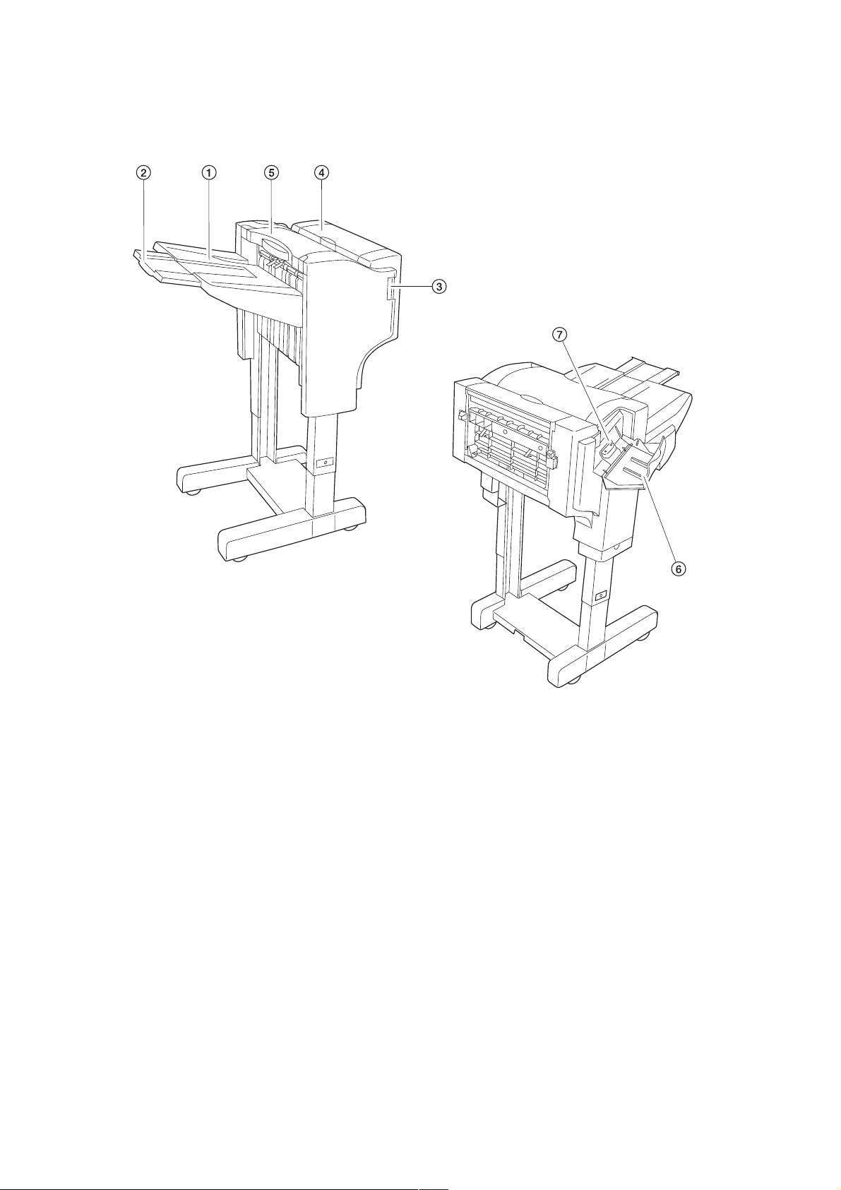
1-1-2 Parts names
1-1-2
Figure 1-1-1
1 Exit tray
2 Exit tray extension
3 Finisher release botton
4 Reverse cover
5 Upper cover
6 Stapler cover
7 Staple holder

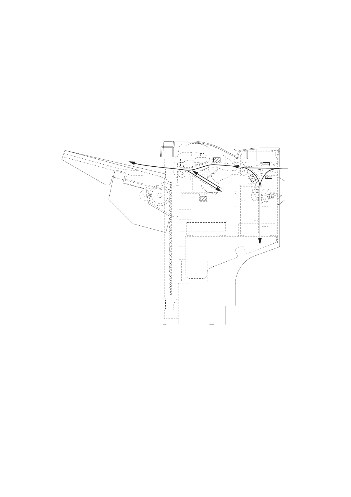
1-1-3 Machine cross section
5HL
Figure 1-1-2 Machine cross section
1 Reverse section
2 Processing section
3 Exit tray section
1-1-3

5HL
1-1-4 Drive system
(1) Drive system 1 (machine front side)
7
6
8
5
4
3
2
1
Figure 1-1-3
1 Paper conveying motor gear
2 Pulley
3 Gear 36/22
4 Gear 32
5 Gear 27/36
6 Gear 22/24
7 Gear 18
8 Gear 85
(2) Drive system 2 (machine rear side)
4
5
3
2
1
7
Figure 1-1-4
6
1 Reverse motor gear
2 Pulley 32
3 Tension pulley
4 Gear 32/20
5 Gear 20
6 Gear 16
7 Gear 32
1-1-4

1-2-1 Unpacking and installation
(1) Unpacking
5HL
1 Document finisher
2 Latch catch
3 Rail retainer
4 Guide rail
5 Joints
6 Outer case
7 Top plate
8 Pad
9 Pad
0 Pad
! Pad
@ Pad
Figure 1-2-1 Unpacking
# Pad
$ Pad
% Pad
^ Hinge joints
& Skid
* Pad
( Supports
) Installation handbook
⁄ Clamp
¤ M4x6 binding screws
‹ M4x10 binding screws
1-2-1
5HL
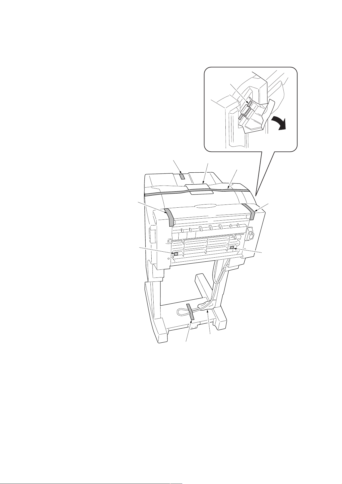
(2) Remove the tapes and pad
When installing the machine, be sure to remove the following tapes and pad.
Procedure
1. Remove the two tapes holding the reverse cover.
2. Remove the two tapes holding the reverse guide.
3. Remove the tape holding the upper cover.
4. Open the upper cover and remove the pad.
5. Remove the tape holding the exit tray extension.
6. Open the stapler cover and remove the tape holding the stapler.
7. Remove the tape holding the signal cable and the air mat.
Tape
Tape
Tape
Tape
Pad
Tape
Tape
Tape
1-2-2
Air mat
Tape
Figure 1-2-2
5HL
1-3-1 Paper misfeed detection
(1) Paper misfeed indication
When a paper jam occurs, the machine stops operating immediately. The copier operation section shows a jam message and
the jam location.
To remove the jammed paper, detach the finisher from the copier.
To reset the paper misfeed detection, turn the joint switch (JSW) off and on.
(2) Paper misfeed detection conditions
PCS
EXS
REVS
PES1
PES2
Figure 1-3-1
1-3-1

5HL
Section Jam code Description Conditions
Reverse
section
80
Paper entry sensor nonarrival jam
The paper entry sensor (PES) is not turned on even if a
specified time has elapsed after the copier exit signal was
received.
Processing
section
81
82
83
84
85
Paper entry sensor stay
jam
Paper entry sensor remaining jam
Reverse sensor non-arrival jam
Reverse sensor stay jam
Reverse sensor remaining jam
Paper conveying sensor
non-arrival jam
Paper conveying sensor
stay jam
The paper entry sensor (PES) is not turned off even if a
specified time has elapsed after the paper entry sensor
(PES) was turned on.
The ON status of the paper entry sensor (PES) is detected
when the power is turned on.
The reverse sensor (REVS) is not turned on even if a specified time has elapsed after the paper entry sensor (PES) was
turned on.
The reverse sensor (REVS) is not turned on even if a specified time has elapsed after paper was reversed.
The reverse sensor (REVS) is not turned off even if a specified time has elapsed after the reverse sensor (REVS) was
turned on.
The ON status of the reverse sensor (REVS) is detected
when the power is turned on.
The paper conveying sensor (PCS) is not turned on even if a
specified time has elapsed after the reverse sensor (REVS)
was turned on.
The paper conveying sensor (PCS) is not turned off even if a
specified time has elapsed after the reverse sensor (REVS)
was turned off.
86
87
Paper conveying sensor
remaining jam
Exit sensor non-arrival
jam
Exit sensor stay jam
Exit sensor remaining
jam
The ON status of the paper conveying sensor (PCS) is detected when the power is turned on.
In the straight mode, the exit sensor (EXS) is not turned on
even if a specified time has elapsed after the paper entry
sensor (PES) was turned on.
In the straight mode, the exit sensor (EXS) is not turned off
even if a specified time has elapsed after the exit sensor
(EXS) was turned on.
In the offset or staple mode, the exit sensor (EXS) is not
turned off when a specified time elapses after the bundle discharge unit starts descending.
The ON status of the exit sensor (EXS) is detected when the
power is turned on.
1-3-2
(3) Paper misfeeds
Problem Causes/check procedures Corrective measures
(1)
An paper jams when
the power switch is
turned on.
Jam code 81, 83,
85, 87
A piece of paper torn from
an paper is caught around
the paper entry sensor.
Defective paper entry sensor.
Check visually and remove it, if any.
With 5 V DC present at CN14-1and CN14-3 on the main PCB,
check if CN14-2 and CN14-4 on the main PCB remains low or
high when the paper entry sensor is turned on and off. If it does,
replace the paper entry sensor.
5HL
A piece of paper torn from
an paper is caught around
the reverse sensor.
Defective reverse sensor.
A piece of paper torn from
an paper is caught around
the paper conveying sensor.
Defective paper conveying
sensor.
A piece of paper torn from
an paper is caught around
the exit sensor.
Defective exit sensor.
Defective main PCB.
Check visually and remove it, if any.
With 5 V DC present at CN14-5 on the main PCB, check if
CN14-7 on the main PCB remains low or high when the reverse
sensor is turned on and off. If it does, replace the reverse sensor.
Check visually and remove it, if any.
With 5 V DC present at CN4-4 on the main PCB, check if CN4-6
on the main PCB remains low or high when the paper conveying
sensor is turned on and off. If it does, replace the paper conveying sensor.
Check visually and remove it, if any.
With 5 V DC present at CN5-4 on the main PCB, check if CN5-6
on the main PCB remains low or high when the exit sensor is
turned on and off. If it does, replace the exit sensor.
Replace the main PCB and check for correct operation.
(2)
An paper jams in
the reverse section
is indicated during
copying (paper entry
sensor non-arrival
jam).
Jam code 80
(3)
An paper jams in
the reverse section
is indicated during
copying (paper entry
sensor stay jam).
Jam code 81
Extremely curled paper.
Defective paper entry sensor.
Check if the paper entry
guide is deformed.
Defective main PCB.
Extremely curled paper.
Defective paper entry sensor.
Check if the paper entry
guide is deformed.
Defective main PCB.
Change the paper.
With 5 V DC present at CN14-1and CN14-3 on the main PCB,
check if CN14-2and CN14-4 on the main PCB remains low or
high when the paper entry sensor is turned on and off. If it does,
replace the paper entry sensor.
Check and remedy.
Replace the main PCB and check for correct operation.
1-3-3
 Loading...