

Page 1
1 / 4
Service Bulletin
SB Number:
SB AS-119 Issue Date: 30/04/2003
Subject: Supply of ‘Special Tool, Stapler’ for field service
Model:
DF-600: KM-4530 / 5530 * / 6330 * (* = with special adjustment only: see SB AS-116)
DF-610: KM-4530 / 5530 / 6330
Please be informed that a part number for the ‘SPECIAL TOOL, STAPLER’ is available.
Please order the ‘SPECIAL TOOL, STAPLER’ with below part number if required.
Purpose
The ‘SPECIAL TOOL, STAPLER’ is a jig that is used when replacing a stapler unit or when a stapling
malfunction occurs. Please refer to page 2 and later of this service bulletin for more details.
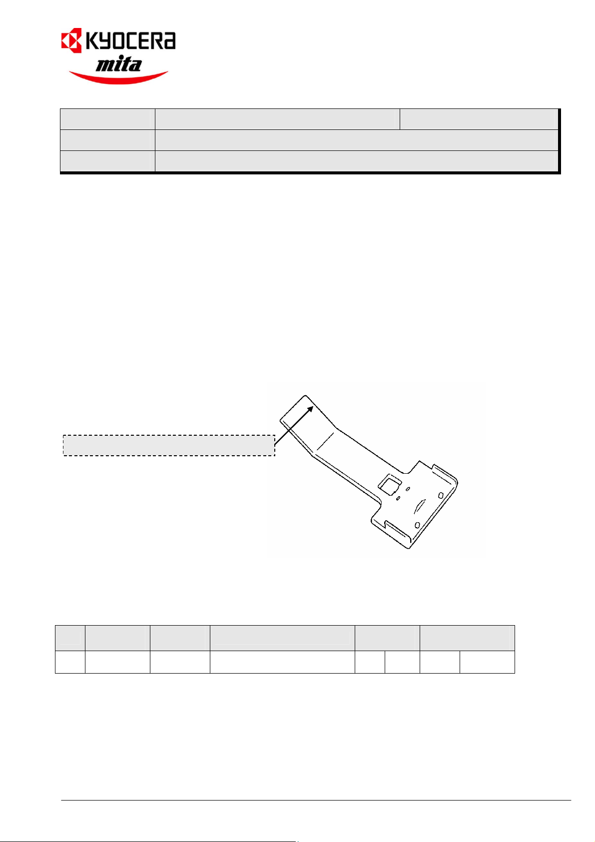
‘SPECIAL TOOL, STAPLER’ (P/N: 3B868010)
Parts Table
No.
Part No.
OLD
DF-600 / DF-610
Part No.
NEW
Description
Q’ty
old-new
Interchange-
ability
1 --------- 3B868010 SPECIAL TOOL, STAPLER - 1
KMIS Service Team, Kyocera Mita Europe 5490 / SB AS-119
- O
Page 2
3B8/9-2
(3) Adjusting the stapler unit mounting position
Perform this operation when replacing a stapler unit or when a stapling malfunction occurs.
* Since the front stapler and the rear stapler in the finisher have the same construction, only the procedure for the front
stapler is described below. Use similar procedure for adjusting the rear stapler.
Tool required for adjustment
• SPECIAL TOOL, STAPLER (P/N 3B868010)
Stapler cartridge
Procedure
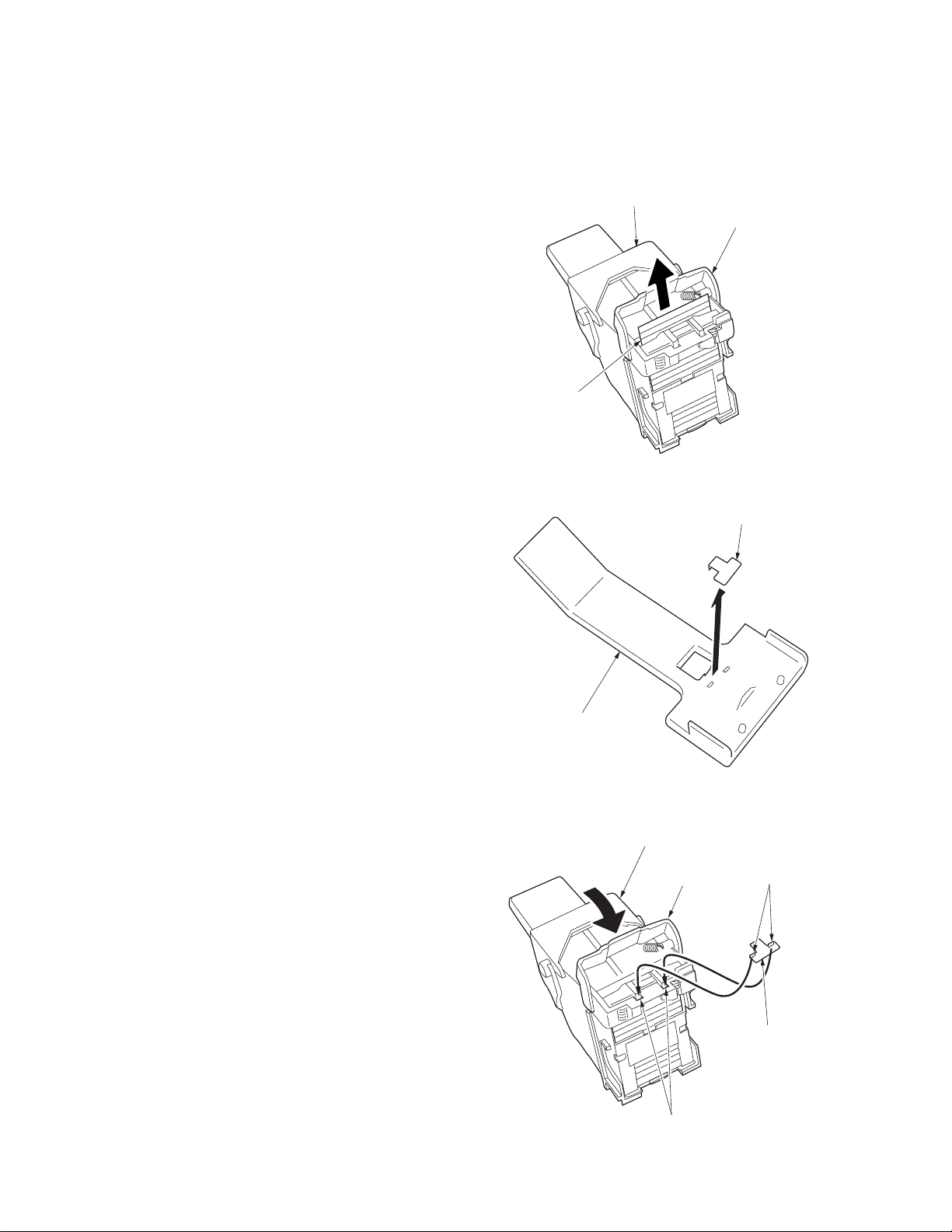
1. Pull out the intermediate tray and remove the
Staple cover
stapler cartridge.
2. Open the staple cover and remove a staple
sheet.
Staple sheet
Figure 1-5-6-1
3. Remove the stapler adjustment metal from the
stapler adjustment tool.
4. Attach the stapler adjustment metal to the
stapler cartridge and close the staple cover.
* Attach the stapler adjustment metal by
inserting its projections into the grooves of the
stapler cartridge.
5. Reattach the stapler cartridge into the stapler.
Stapler adjustment tool
Figure 1-5-6-2
Stapler cartridge
Stapler adjustment metal
Staple cover
Projections
Grooves
Figure 1-5-6-3
Stapler adjustment
metal
1-5-31-5-2-1
Page 3

3B8/9-2
6. Open the intermediate tray and attach the
stapler adjustment tool to the stapler.
* Attach the stapler adjustment tool by inserting
its projections into the stapler holes. In
addition, be careful not to get the film caught
when attaching the tool.
7. Close the intermediate tray.
* Do not carry out step 8 with the intermediate
tray open because the stapler may be
damaged.
8. Turn the gear manually to push the stapler into
the inner part and ensure that the stapler
adjustment metal is inserted smoothly into the
adjustment hole of the stapler adjustment tool.
Stapler adjustment tool
Projections
Figure 1-5-6-4
Stapler
Holes
Film
Stapler
1-5-41-5-2-2
Gear
Figure 1-5-6-5
Stapler adjustment tool
Adjustment hole
Stapler adjustment metal
Figure 1-5-6-6
Page 4

3B8/9-2
9. If the stapler adjustment metal is not inserted
into the adjustment hole, loosen the four
adjustment screws on the intermediate tray
and adjust the stapler unit mounting position
so that the metal is inserted into the hole.
* At this time, turn the gear manually
furthermore and ensure that the stapler is
securely pushed into the inner part.
10. Tighten the adjustment screws in the order
shown below.
1
Tighten the upper two screws loosely.
2
Tighten the lower two screws loosely.
3
Finally tighten the upper two screws.
4
Finally tighten the lower two screws.
11. Turn the gear manually to pull back the stapler
to its original position and then remove the
stapler cartridge.
12. Remove the stapler adjustment metal and the
stapler adjustment tool.
13. With the stapler cartridge removed, return the
intermediate tray to its original position and
mount the finisher to the copier. Turn the
copier main switch on (to detect the noncartridge status).
14. Pull out the intermediate tray again and attach
the stapler cartridge. Mount the finisher to the
copier and turn the main switch on.
Intermediate tray
Adjustment screws
Adjustment screws
Figure 1-5-6-7
15. Select the staple mode (mode specifying the
stapler that has been adjusted) and carry out
this mode.
* After the staples in the cartridge are
automatically fed in test stapling, the staple
mode will be carried out.
16. Check the shape of the staples on the rear
side that have been used in the test stapling
and the staple mode above.
* If the shape is defective, perform the
adjustment again.
Shape of staples on the rear side
Normal Defective
> 0.5mm
a
a
<
0.5mm
=
a
a
1-5-5
1-5-2-3
 Loading...