

Page 1

DF-470
SERVICE
MANUAL
Published in October 2010
845JS110
5JSSM060
First Edition
Page 2

CAUTION
RISK OF EXPLOSION IF BATTERY IS REPLACED BY AN INCORRECT TYPE. DISPOSE
OF USED BATTERIES ACCORDING TO THE INSTRUCTIONS.
It may be illegal to dispose of this battery into the municipal waste stream. Check with your
local solid waste officials for details in your area for proper disposal.
ATTENTION
IL Y A UN RISQUE D’EXPLOSION SI LA BATTERIE EST REMPLACEE PAR UN MODELE
DE TYPE INCORRECT. METTRE AU REBUT LES BATTERIES UTILISEES SELON LES
INSTRUCTIONS DONNEES.
Il peut être illégal de jeter les batteries dans des eaux d’égout municipales. Vérifiez avec les
fonctionnaires municipaux de votre région pour les détails concernant des déchets solides
et une mise au rebut appropriée.
Page 3

Revision history
Revision Date Replaced pages Remarks
Page 4

This page is intentionally left blank.
Page 5

Safety precautions
This booklet provides safety warnings and precautions for our service personnel to ensure the safety of
their customers, their machines as well as themselves during maintenance activities. Service personnel
are advised to read this booklet carefully to familiarize themselves with the warnings and precautions
described here before engaging in maintenance activities.
Page 6
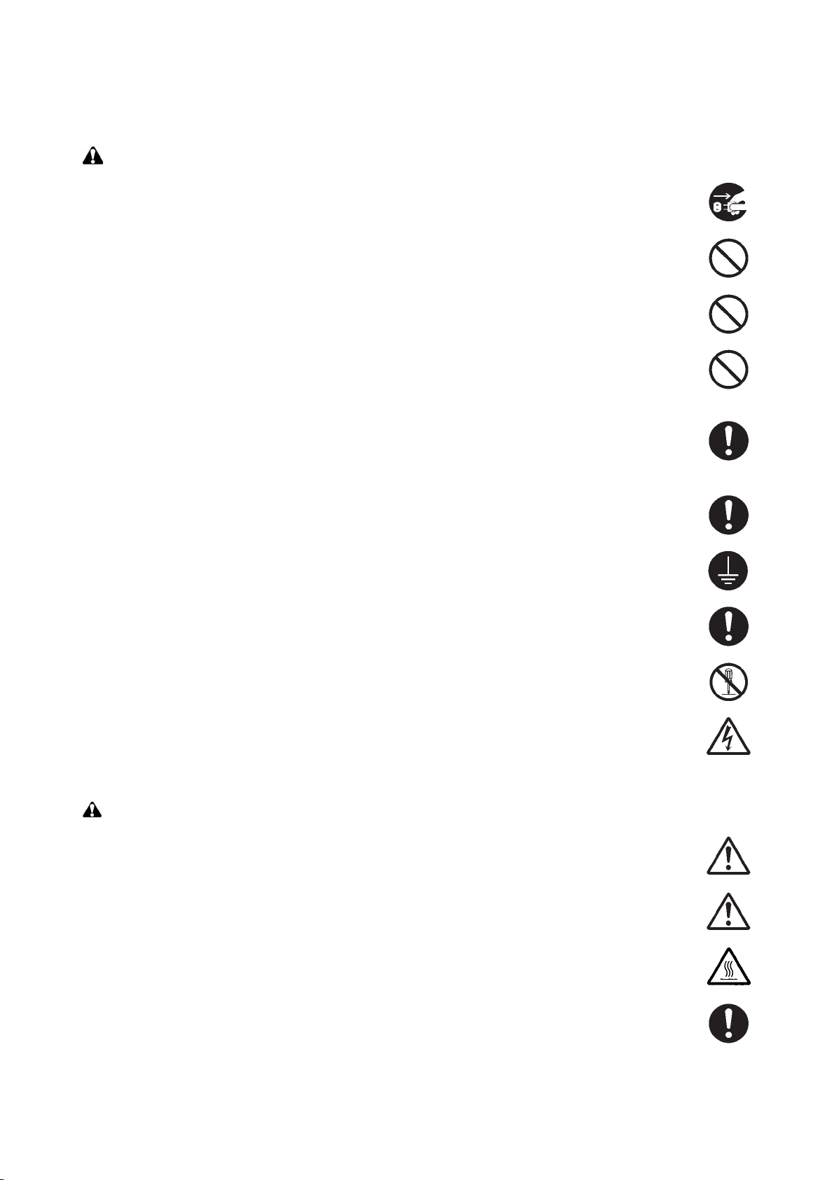
Safety warnings and precautions
Various symbols are used to protect our service personnel and customers from physical danger and
to prevent damage to their property. These symbols are described below:
DANGER: High risk of serious bodily injury or death may result from insufficient attention to or incorrect
compliance with warning messages using this symbol.
WARNING: Serious bodily injury or death may result from insufficient attention to or incorrect compliance
with warning messages using this symbol.
CAUTION: Bodily injury or damage to property may result from insufficient attention to or incorrect com-
pliance with warning messages using this symbol.
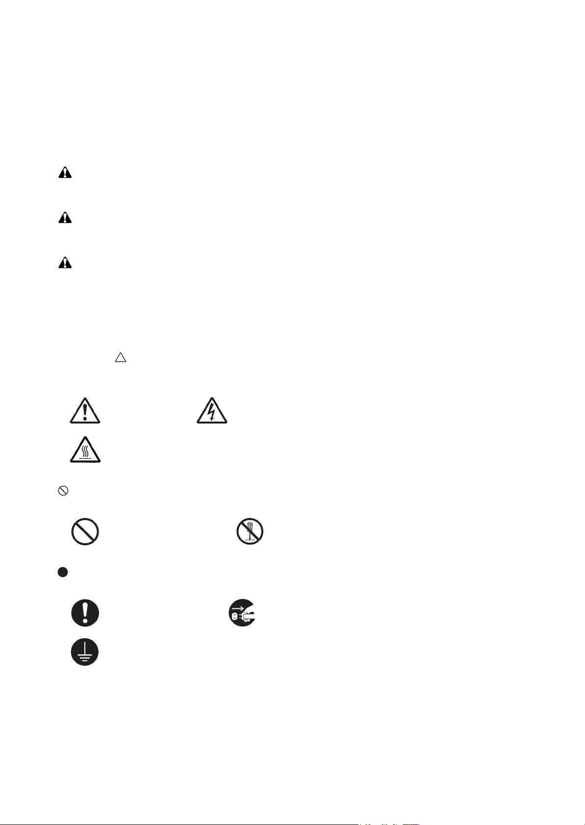
Symbols
The triangle ( ) symbol indicates a warning including danger and caution. The specific point of attention is
shown inside the symbol.
General warning. Warning of risk of electric shock.
Warning of high temperature.
indicates a prohibited action. The specific prohibition is shown inside the symbol.
General prohibited action. Disassembly prohibited.
indicates that action is required. The specific action required is shown inside the symbol.
General action required. Remove the power plug from the wall outlet.
Always ground the copier.
Page 7

1. Installation Precautions
WARNING
• Do not use a power supply with a voltage other than that specified. Avoid multiple connections to
one outlet: they may cause fire or electric shock. When using an extension cable, always check that
it is adequate for the rated current. .....................................................................................................
• Connect the ground wire to a suitable grounding point. Not grounding the copier may cause fire or
electric shock. Connecting the earth wire to an object not approved for the purpose may cause
explosion or electric shock. Never connect the ground cable to any of the following: gas pipes, lightning rods, ground cables for telephone lines and water pipes or faucets not approved by the proper
authorities. ..........................................................................................................................................
CAUTION:
• Do not place the copier on an infirm or angled surface: the copier may tip over, causing injury. .........
• Do not install the copier in a humid or dusty place. This may cause fire or electric shock. .................
• Do not install the copier near a radiator, heater, other heat source or near flammable material. This
may cause fire. ...................................................................................................................................
• Allow sufficient space around the copier to allow the ventilation grills to keep the machine as cool
as possible. Insufficient ventilation may cause heat buildup and poor copying performance. ............
• Always handle the machine by the correct locations when moving it. .................................................
• Always use anti-toppling and locking devices on copiers so equipped. Failure to do this may cause
the copier to move unexpectedly or topple, leading to injury. ..............................................................
• Avoid inhaling toner or developer excessively. Protect the eyes. If toner or developer is accidentally
ingested, drink a lot of water to dilute it in the stomach and obtain medical attention immediately.
If it gets into the eyes, rinse immediately with copious amounts of water and obtain medical atten-
tion. .....................................................................................................................................................
• Advice customers that they must always follow the safety warnings and precautions in the copier’s
instruction handbook. .........................................................................................................................
Page 8
2. Precautions for Maintenance
WARNING
• Always remove the power plug from the wall outlet before starting machine disassembly. ................
• Always follow the procedures for maintenance described in the service manual and other related
brochures. ..........................................................................................................................................
• Under no circumstances attempt to bypass or disable safety features including safety mechanisms
and protective circuits. ........................................................................................................................
• Always use parts having the correct specifications. ............................................................................
• Always use the thermostat or thermal fuse specified in the service manual or other related brochure
when replacing them. Using a piece of wire, for example, could lead to fire or other serious acci-
dent. ...................................................................................................................................................
• When the service manual or other serious brochure specifies a distance or gap for installation of a
part, always use the correct scale and measure carefully. ..................................................................
• Always check that the copier is correctly connected to an outlet with a ground connection. ...............
• Check that the power cable covering is free of damage. Check that the power plug is dust-free. If it
is dirty, clean it to remove the risk of fire or electric shock. .................................................................
• Never attempt to disassemble the optical unit in machines using lasers. Leaking laser light may
damage eyesight. ...............................................................................................................................
• Handle the charger sections with care. They are charged to high potentials and may cause electric
shock if handled improperly. ...............................................................................................................
CAUTION
• Wear safe clothing. If wearing loose clothing or accessories such as ties, make sure they are safely
secured so they will not be caught in rotating sections. ......................................................................
• Use utmost caution when working on a powered machine. Keep away from chains and belts. ..........
• Handle the fixing section with care to avoid burns as it can be extremely hot. ..................................
• Check that the fixing unit thermistor, heat and press rollers are clean. Dirt on them can cause
abnormally high temperatures. ...........................................................................................................
Page 9

• Do not remove the ozone filter, if any, from the copier except for routine replacement. ......................
• Do not pull on the AC power cord or connector wires on high-voltage components when removing
them; always hold the plug itself. ........................................................................................................
• Do not route the power cable where it may be stood on or trapped. If necessary, protect it with a
cable cover or other appropriate item. ................................................................................................
• Treat the ends of the wire carefully when installing a new charger wire to avoid electric leaks. ..........
• Remove toner completely from electronic components. .....................................................................
• Run wire harnesses carefully so that wires will not be trapped or damaged. ......................................
• After maintenance, always check that all the parts, screws, connectors and wires that were
removed, have been refitted correctly. Special attention should be paid to any forgotten connector,
trapped wire and missing screws. .......................................................................................................
• Check that all the caution labels that should be present on the machine according to the instruction
handbook are clean and not peeling. Replace with new ones if necessary. .......................................
• Handle greases and solvents with care by following the instructions below: ......................................
· Use only a small amount of solvent at a time, being careful not to spill. Wipe spills off completely.
· Ventilate the room well while using grease or solvents.
· Allow applied solvents to evaporate completely before refitting the covers or turning the power
switch on.
· Always wash hands afterwards.
• Never dispose of toner or toner bottles in fire. Toner may cause sparks when exposed directly to
fire in a furnace, etc. ...........................................................................................................................
• Should smoke be seen coming from the copier, remove the power plug from the wall outlet immedi-
ately. ...................................................................................................................................................
3. Miscellaneous
WARNING
• Never attempt to heat the drum or expose it to any organic solvents such as alcohol, other than the
specified refiner; it may generate toxic gas. ........................................................................................
Page 10

This page is intentionally left blank.
Page 11

CONTENTS
1-1 Specifications
1-1-1 Specifications ........................................................................................................................ 1-1-1
1-1-2 Parts names .......................................................................................................................... 1-1-2
1-1-3 Machine cross section ........................................................................................................... 1-1-3
1-2 Installation
1-2-1 Installation environment......................................................................................................... 1-2-1
1-2-2 Unpacking.............................................................................................................................. 1-2-2
(1) Unpacking......................................................................................................................... 1-2-2
(2) Removing the tapes and pads.......................................................................................... 1-2-4
1-3 Maintenance Mode
1-3-1 Maintenance mode ................................................................................................................ 1-3-1
(1) Executing a maintenance item ......................................................................................... 1-3-1
(2) Contents of the maintenance mode items ........................................................................ 1-3-2
1-4 Troubleshooting
1-4-1 Paper misfeed detection ........................................................................................................ 1-4-1
(1) Paper misfeed indication .................................................................................................. 1-4-1
(2) Paper misfeed detection condition ................................................................................... 1-4-1
1-4-2 Self-diagnostic function ......................................................................................................... 1-4-4
(1) Self-diagnostic function .................................................................................................... 1-4-4
(2) Self diagnostic codes........................................................................................................ 1-4-4
1-4-3 Electric problems ................................................................................................................... 1-4-9
1-4-4 Mechanical problems........................................................................................................... 1-4-12
5JS
1-5 Assembly and disassembly
1-5-1 Precautions for assembly and disassembly........................................................................... 1-5-1
(1) Precautions....................................................................................................................... 1-5-1
1-5-2 Outer covers .......................................................................................................................... 1-5-2
(1) Detaching and refitting the rear cover and front cover ..................................................... 1-5-2
(2) Gear phase adjustment for vertical driving of bundle discharge belt................................ 1-5-3
2-1 Mechanical Construction
2-1-1 Bridge unit section ................................................................................................................. 2-1-1
2-1-2 Prosessing section ................................................................................................................ 2-1-3
(1) Bundle discharge operation.............................................................................................. 2-1-5
2-1-3 Eject tray section ................................................................................................................... 2-1-6
2-2 Electrical Parts Layout
2-2-1 Electrical parts layout ............................................................................................................ 2-2-1
(1) PWBs................................................................................................................................ 2-2-1
(2) Switches and sensors....................................................................................................... 2-2-2
(3) Motors............................................................................................................................... 2-2-3
(4) Solenoids.......................................................................................................................... 2-2-4
(5) Bridge section................................................................................................................... 2-2-5
2-3 Operation of the PWBs
2-3-1 DF main PWB ........................................................................................................................ 2-3-1
2-3-2 Bridge PWB ........................................................................................................................... 2-3-6
Page 12

2-4 Appendixes
2-4-1 Appendixes............................................................................................................................ 2-4-1
(1) Wiring diagram ................................................................................................................. 2-4-1
5JS
Page 13

1-1 Specifications
1-1-1 Specifications
Item Specifications
Type Hunger model
Number of trays One tray
Paper weight 52 to 256 g/m
5JS
2
Tray capacity
Stapling capacity
Paper weight 90 g/m
Dimensions (W × D × H)
When not stapling
When stapling 2 or 10
sheets
When stapling 11 or
20 sheets
When stapling 21 or
30 sheets
When stapling 31 or
A3, B4, Ledger, Legal, Oficio II, 216 x 340mm, 8K: 250 sheets
A4, A4R, B5, B5R, Letter, LetterR, ExecutiveR, 16K: 500 sheets
A3, B4, Ledger, Legal, 8K: 22 sets
A4R, LetterR: 40 sets
A4, B5,Letter, 16K: 45 sets
A3, B4, Ledger, Legal, 8K: 11 sets
A4R, LetterR: 20 sets
A4, B5,Letter, 16K: 22 sets
A3, B4, Ledger, Legal, 8K: 9 sets
A4, A4R, B5, Letter, LetterR, 16K: 15 sets
A4, A4R, B5, Letter, LetterR, 16K: 9 sets
50 sheets
A3, B4, Ledger, Legal, 216 x 340mm, 8K: 25 sheets
2
or less
416 × 521 × 275.5 mm
16 3/8 × 20 1/2 × 10 7/8”
Weight Approx 12 kg/26.4 lb
NOTE: These specifications are subject to change without notice.
1-1-1
Page 14
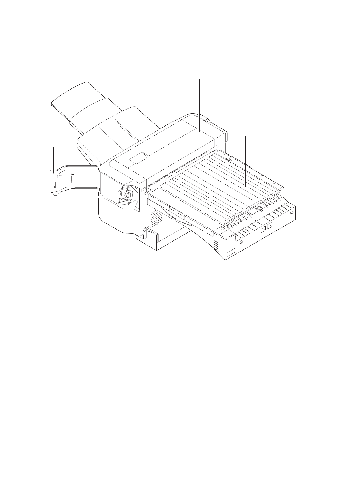
1-1-2 Parts names
1. Finisher tray
2. Finisher tray extension
3. DF top cover
4. Staple cover
5. Staple holder
6. Bridge unit cover
5JS
2
13
6
4
5
Figure 1-1-1
1-1-2
Page 15
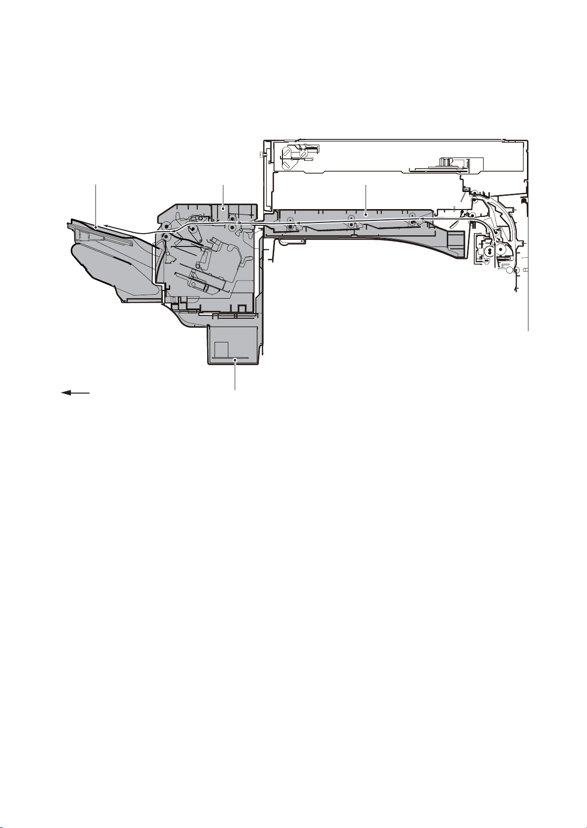
1-1-3 Machine cross section
1. Bridge unit section
2. Finisher processing section
3. Eject tray section
4. Power source unit section
5JS
3
Paper path
2
1
4
Figure 1-1-2
1-1-3
Page 16

5JS
1-2 Installation
1-2-1 Installation environment
Installation location
Avoid direct sunlight or bright lighting. Ensure that the photoconductor will not be exposed to direct sunlight or
other strong light when removing paper jams.
Avoid locations subject to high temperature and high humidity or low temperature and low humidity; an abrupt
change in the environmental temperature; and cool or hot, direct air.
Avoid places subject to dust and vibrations.
Choose a surface capable of supporting the weight of the machine.
Place the machine on a level surface (maximum allowance inclination: 1°).
Avoid air-borne substances that may adversely affect the machine or degrade the photoconductor, such as
mercury, acidic of alkaline vapors, inorganic gasses, NOx, SOx gases and chlorine-based organic solvents.
Select a well-ventilated location.
1-2-1
Page 17
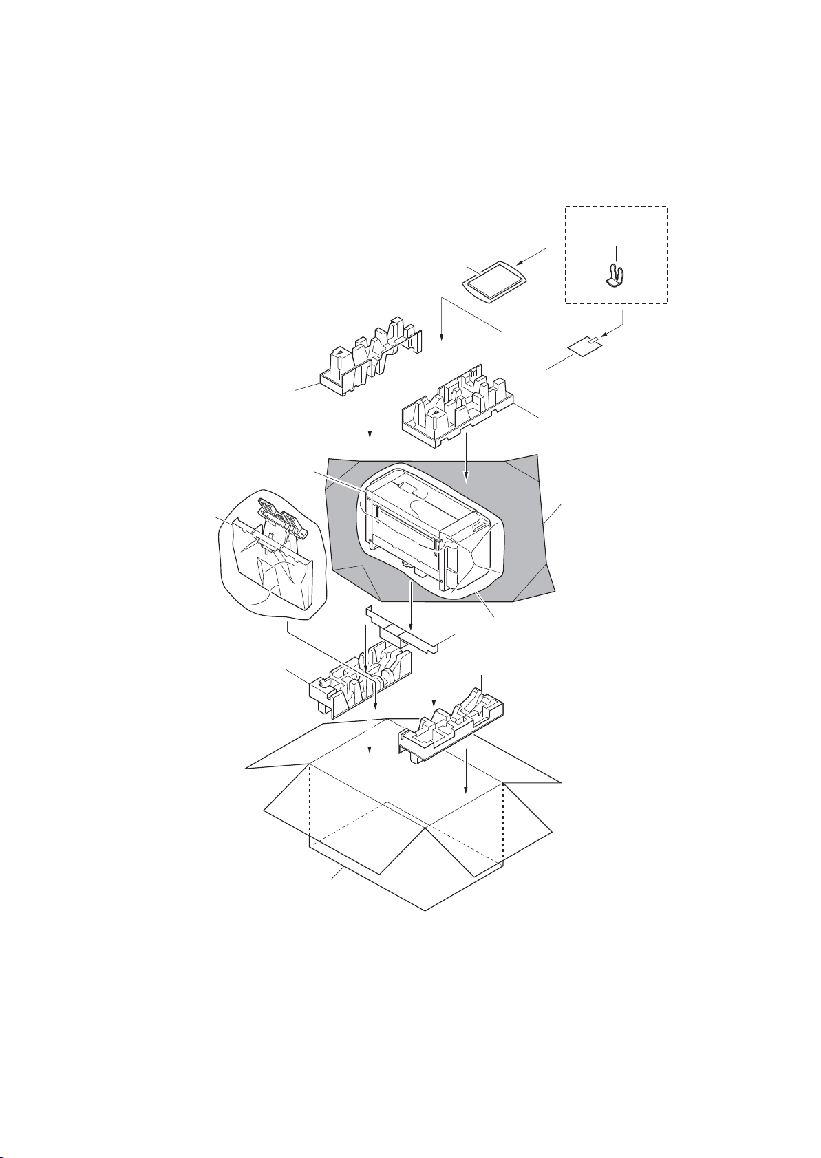
1-2-2 Unpacking
1. Finisher
2. Outer case
3. Plastic sheet
4. Plastic sheet
5. Bottom left pad
6. Bottom right pad
7. Spacer
8. Upper left pad
9. Upper right pad
10. Finisher tray
11. Installation guide
12. Stop Rings
(1) Unpacking
Finisher
5JS
12
11
8
9
10
1
4
3
7
65
2
Figure 1-2-1
1-2-2
Page 18
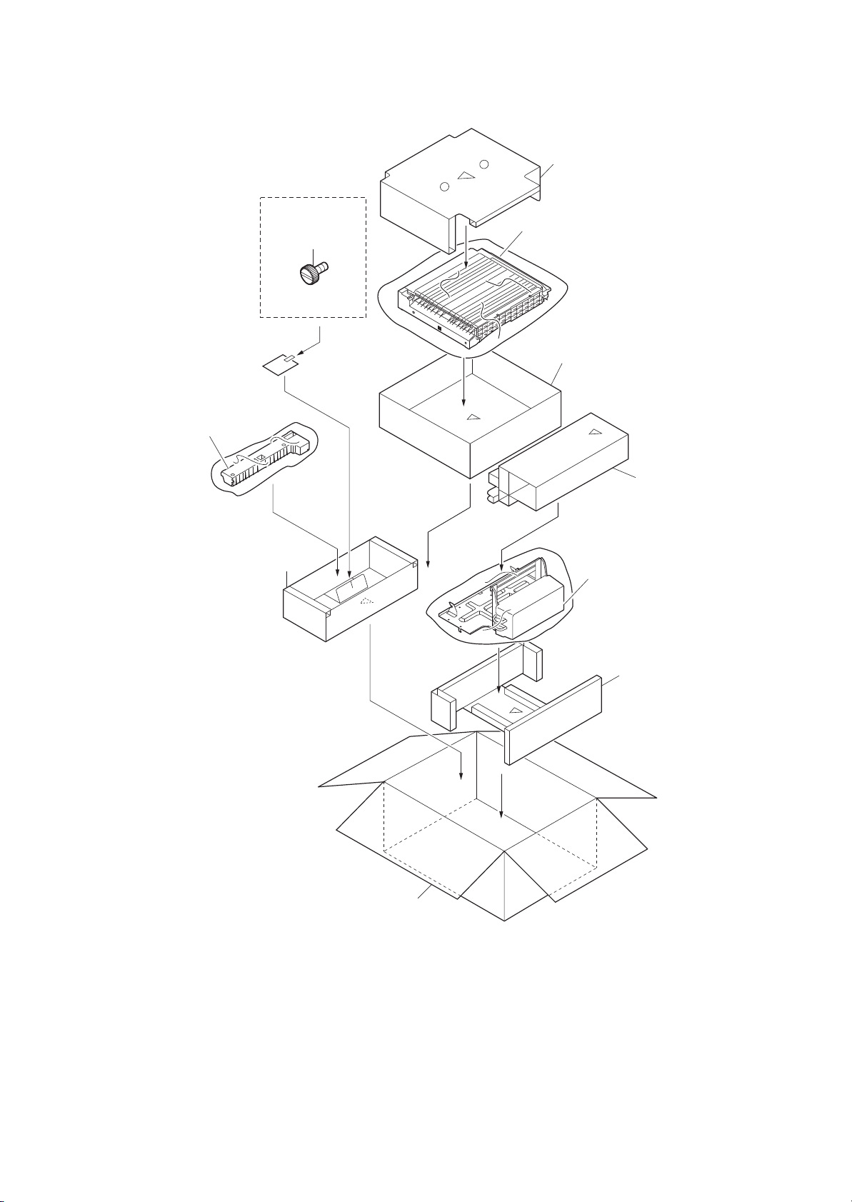
Bridge unit
1. Power source unit
2. Outer case
3. Main pad
4. Bottom spacer
5. Lower right guide
6. Top spacer
7. Bridge unit
8. Bridge case
9. Top pad
10. Pins
5JS
9
7
10
8
5
6
4
1
3
2
Figure 1-2-2
See the Installation Guide for installation.
1-2-3
Page 19
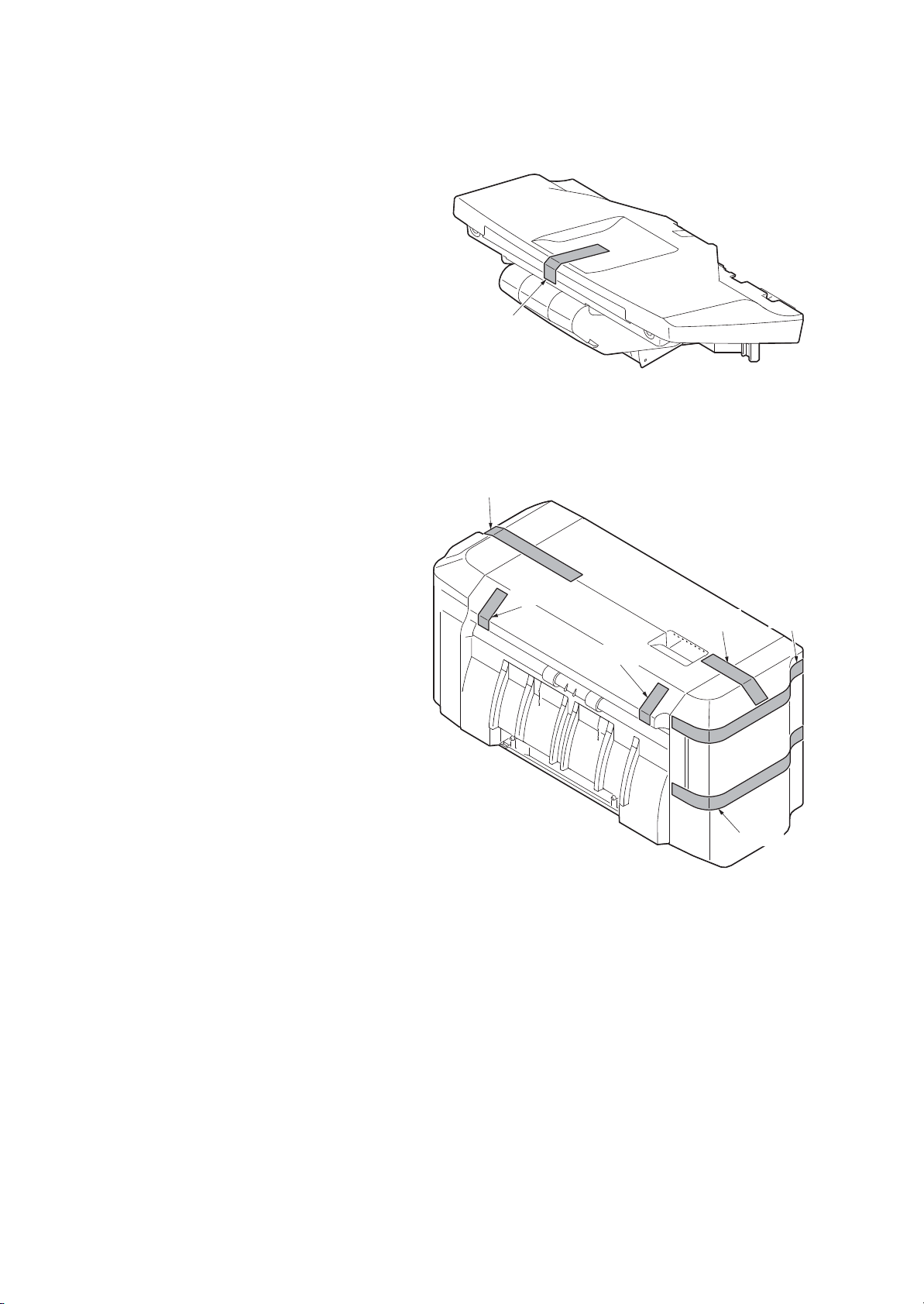
(2) Removing the tapes and pads
1. Remove tape from the finisher try.
5JS
Ta pe
Figure 1-2-3
2. Remove six tapes from the document
finisher.
Ta pe
Ta pe
Ta pe
Figure 1-2-4
Ta pe
Ta pe
Ta pe
1-2-4
Page 20
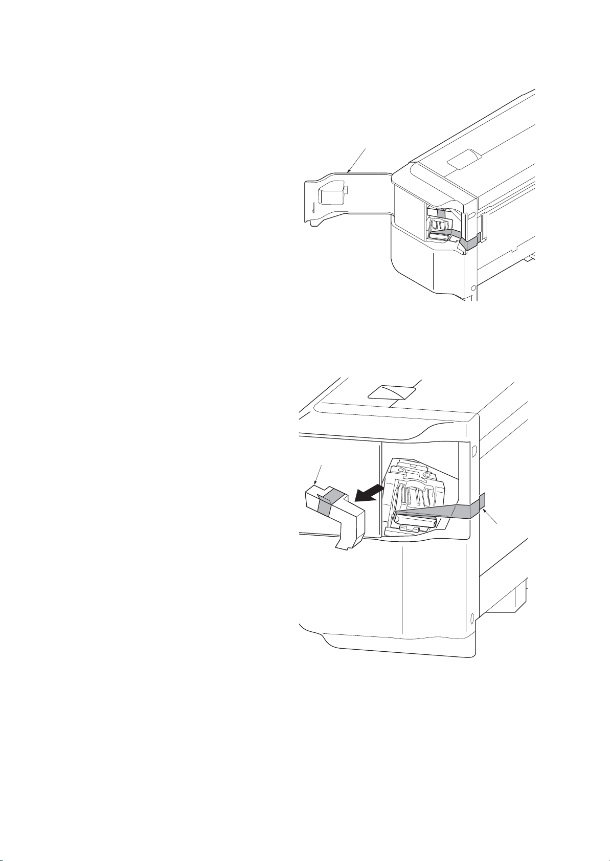
3. Open the staple cover.
Tap e
Pad
5JS
Staple cover
Figure 1-2-5
4. Remove tape and pad.
Figure 1-2-6
1-2-5
Page 21

5JS
5. Remove three tapes from bridge unit.
Tap e
Tap e
Tap e
Figure 1-2-7
6. Remove two tapes from power source
unit.
Tap e
Tap e
Figure 1-2-8
1-2-6
Page 22

1-3 Maintenance Mode
1-3-1 Maintenance mode
The machine is equipped with a maintenance function which can be used to maintain and service the
machine.
(1) Executing a maintenance item
Start
5JS
Enter “10871087” using
the numeric keys.
Enter the maintenance item
number using the cursor left/right keys
or numeric keys.
Press the start key.
The selected maintenance item is run.
Press the stop key.
Yes
Repeat the same
maintenance item?
Maintenance mode is entered.
The maintenance item is selected.
No
Yes
Run another maintenance
item?
No
Turn the main power switch off and on.
End
Maintenance mode is exited and
the system is restarted to initialize it
and to reflect the setting changes.
1-3-1
Page 23

(2) Contents of the maintenance mode items
Display Description
Main Main ROM
MMI Operation ROM
Engine Engine ROM
Engine Boot Engine booting
RFID RFID ROM
IO CPU IO CPU ROM
IO CPU Boot IO CPU booting
Option Language Optional language ROM
Dictionary -
DP Document processor ROM
DP Boot Document processor booting
PF Paper feeder ROM
PF Boot Paper feeder booting
DF Document finisher ROM
DF Boot Document finisher booting
AK Bridge ROM
AK Boot Bridge booting
Fax APL Fax control PWB APL
Fax Boot Fax control PWB booting
Fax IPL Fax control PWB IPL
Item No. Description
U019 Displaying the ROM version
Description
Displays the part number of the ROM fitted to each PWB.
Purpose
To check the part number or to decide, if the newest version of ROM is installed.
Method
1. Press the start key. The ROM version are displayed.
2. Change the screen using the cursor up/down keys.
5JS
Completion
Press the stop key. The screen for selecting a maintenance item No. is displayed.
1-3-2
Page 24

Item No. Description
Display Description
DP Counts of document processor
DF Counts of document finisher
Display Description
ADP Counts of single-sided originals that has passed through the DP
RADP Counts of double-sided originals that has passed through the DP
Display Description
Sorter Counts of copies that has passed through the sorter
Staple Frequency the stapler has been activated
U905 Checking counts by optional devices
Description
Displays the counts of document processor or document finisher.
Purpose
To check the use of document processor or document finisher.
Method
1. Press the start key.
2. Select the device to be checked. The count of the selected device is displayed.
DP
5JS
DF
Completion
Press the stop key. The screen for selecting a maintenance item No. is displayed.
1-3-3
Page 25

5JS
This page is intentionally left blank.
1-3-4
Page 26

5JS
EPS
PCS
1-4 Troubleshooting
1-4-1 Paper misfeed detection
(1) Paper misfeed indication
When a paper misfeed occurs, the machine immediately stops printing and displays the paper misfeed message on the operation panel. To remove paper misfed in the machine, open the DF top cover or bridge cover.
(2) Paper misfeed detection condition
BRPCS3
Figure 1-4-1 Paper jam location
BRPCS2
BRPCS1
1-4-1
Page 27

Code Contents Conditions
5JS
4901 Bridge conveying sensor 1
non arrival jam
4902 The bridge conveying sensor 1 (BRCS1) does not turn on dur-
4903 The bridge conveying sensor 1 (BRCS1) does not turn on dur-
4908 The bridge conveying sensor 1 (BRCS1) does not turn on dur-
4909 The bridge conveying sensor 1 (BRCS1) does not turn on dur-
4911 Bridge conveying sensor 1
stay jam
4912 The bridge conveying sensor 1 (BRCS1) does not turn off dur-
4913 The bridge conveying sensor 1 (BRCS1) does not turn off dur-
4918 The bridge conveying sensor 1 (BRCS1) does not turn off dur-
4919 The bridge conveying sensor 1 (BRCS1) does not turn off dur-
The bridge conveying sensor 1 (BRCS1) does not turn on during paper feed from cassette 1.
ing paper feed from cassette 2.
ing paper feed from cassette 3.
ing paper feed from duplex section.
ing paper feed from MP tray.
The bridge conveying sensor 1 (BRCS1) does not turn off during paper feed from cassette 1.
ing paper feed from cassette 2.
ing paper feed from cassette 3.
ing paper feed from duplex section.
ing paper feed from MP tray.
5001 Bridge conveying sensor 3
non arrival jam
5002 The bridge conveying sensor 3 (BRCS3) does not turn on dur-
5003 The bridge conveying sensor 3 (BRCS3) does not turn on dur-
5008 The bridge conveying sensor 3 (BRCS3) does not turn on dur-
5009 The bridge conveying sensor 3 (BRCS3) does not turn on dur-
5011 Bridge conveying sensor 3
stay jam
5012 The bridge conveying sensor 3 (BRCS3) does not turn off dur-
5013 The bridge conveying sensor 3 (BRCS3) does not turn off dur-
5018 The bridge conveying sensor 3 (BRCS3) does not turn off dur-
5019 The bridge conveying sensor 3 (BRCS3) does not turn off dur-
The bridge conveying sensor 3 (BRCS3) does not turn on during paper feed from cassette 1.
ing paper feed from cassette 2.
ing paper feed from cassette 3.
ing paper feed from duplex section.
ing paper feed from MP tray.
The bridge conveying sensor 3 (BRCS3) does not turn off during paper feed from cassette 1.
ing paper feed from cassette 2.
ing paper feed from cassette 3.
ing paper feed from duplex section.
ing paper feed from MP tray.
6023 Staple cover open The staple cover is opened during operation.
6043 DF top cover open The DF top cover is opened during operation.
1-4-2
Page 28

Code Contents Conditions
5JS
6103 DF paper conveying sensor
non arrival jam
6113 DF paper conveying sensor
stay jam
6123 DF paper conveying sensor
remaining jam
6413 DF eject paper sensor stay
jam
6423 DF eject paper sensor remain-
ing jam
6803 Front adjustment plete opera-
tion ON error
6813 Front adjustment plete opera-
tion OFF error
6903 Rear adjustment plete opera-
tion ON error
6913 Rear adjustment plete opera-
tion OFF error
The paper conveying sensor (PCS) does not turned on even if
a specified time has elapsed after the machine eject signal
was received.
The paper conveying sensor (PCS) does not turn off within
specified time of its turning on.
The paper conveying sensor (PCS) does turned on when the
power is turned on or cover close.
The eject paper sensor (EPS) does not turn off within specified
time of its turning on.
The eject paper sensor (EPS) does turned on when the power
is turned on or cover close.
The adjustment sensor 1 (ADS1) does turned on when job is
executed.
The adjustment sensor 1 (ADS1) does turned off when job is
executed.
The adjustment sensor 2 (ADS2) does turned on when job is
executed.
The adjustment sensor 2 (ADS2) does turned off when job is
executed.
7013 Staple opration error The next staple hasn't head-poked for the next copy to bind
after a predetermined interval while clinching has commenced.
7023 Staple initialopration error Head-poking has not been accomplished after 10 attempts in
the initialization at power up or closing the cover.
7913 Sequence error 1
(operation prohibited)
7923 Sequence error 2
(initialopration error)
7933 Sequence error 3
(Error in the reception of
backup data)
7943 Sequence error 4
(standby)
7953 Sequence error 5
(Error inbetween copies)
Operation commenced in the state the finisher is prohibited to
operate.
A request for maintenance mode has occurred in the state the
finisher is prohibited to operate or has commenced operation.
A backup data command has been received in the state the
operation has initiated.
Start of operation has been received in the state of prohibiting
to stand by.
An illegal inter-page or inter-copy interval has occurred.
1-4-3
Page 29

5JS
1-4-2 Self-diagnostic function
(1) Self-diagnostic function
This machine is equipped with self-diagnostic function. When a problem is detected, the machine stops printing and display an error message on the operation panel. An error message consists of a message prompting
a contact to service personnel and a four-digit error code indicating the type of the error.
(2) Self diagnostic codes
If the part causing the problem was not supplied, use the unit including the part for replacement.
Code Contents Causes
8030 Tray upper limit detection
problem (document finisher)
When the tray elevation motor
raises a tray, the ON status of
the tray upper limit sensor is
detected.
8040 Belt problem (document fin-
isher)
The belt sensor does not turn
on/off within specified time of
the belt solenoid turning on.
Defective connector cable or poor
contact in the connector.
Defective tray
upper limit sensor,
paper surface sensor 1/2.
Defective DF main
PWB.
Defective connector cable or poor
contact in the connector.
Defective belt sensor.
Check procedures/
corrective measures
Reinsert the connector. Also check for continuity within the connector cable. If none,
replace the cable.
Tray upper limit sensor and DF main PWB
(CN5)
Paper surface sensor 1/2 and DF main PWB
(CN6)
Replace the sensor.
Replace the DF main PWB and check for
correct operation.
Reinsert the connector. Also check for continuity within the connector cable. If none,
replace the cable.
Belt sensor and DF main PWB (CN10)
Belt solenoid and DF main PWB (CN21)
Replace the belt sensor.
Defective belt solenoid.
Defective DF main
PWB.
1-4-4
Replace the belt solenoid.
Replace the DF main PWB and check for
correct operation.
Page 30

5JS
Code Contents Causes
8140 Tray elevation motor prob-
lem (document finisher)
The tray low limit sensor or
paper surface sensor 1/2 cannot be detected to be on
within 10 s since the tray elevation motor is activated.
Defective connector cable or poor
contact in the connector.
Defective connector cable or poor
contact in the connector.
The tray elevation
motor malfunctions.
Defective tray
lower limit sensor,
paper surface sensor 1/2.
Check procedures/
corrective measures
Reinsert the connector. Also check for continuity within the connector cable. If none,
replace the cable.
Tray elevation motor and DF main PWB
(CN15)
Reinsert the connector. Also check for continuity within the connector cable. If none,
replace the cable.
Tray lower limit sensor and DF main PWB
(CN5)
Paper surface sensor 1/2 and DF main PWB
(CN6)
Replace the tray elevation motor.
Replace the sensor.
8210 Stapler problem (document
finisher)
Jam 7012 or 7023 is indicated.
Defective DF main
PWB.
Defective connector cable of staple
or poor contact in
the connector.
The stapler is
blocked with a staple.
The stapler is broken.
Defective DF main
PWB.
Replace the DF main PWB and check for
correct operation.
Reinsert the connector. Also check for continuity within the connector cable. If none,
replace the cable.
Remove the stapler cartridge, and check the
cartridge and the stapling section of the stapler.
Replace the stapler and check for correct
operation.
Replace the DF main PWB and check for
correct operation.
1-4-5
Page 31

5JS
Code Contents Causes
8320 Adjustment motor 2 prob-
lem (document finisher)
The adjustment sensor 2 does
not turn on/off within specified
time of the adjustment motor 2
turning on.
8330 Adjustment motor 1 prob-
lem (document finisher)
The adjustment sensor 1 does
not turn on/off within specified
time of the adjustment motor 1
turning on.
Defective connector cable or poor
contact in the connector.
Defective adjustment sensor 2.
Defective adjustment motor 2.
Defective DF main
PWB.
Defective connector cable or poor
contact in the connector.
Check procedures/
corrective measures
Reinsert the connector. Also check for continuity within the connector cable. If none,
replace the cable.
Adjustment motor 2 and DF main PWB
(CN18)
Adjustment sensor 2 and DF main PWB
(CN7)
Replace the adjustment sensor 2.
Replace the adjustment motor 2.
Replace the DF main PWB and check for
correct operation.
Reinsert the connector. Also check for continuity within the connector cable. If none,
replace the cable.
Adjustment motor 1 and DF main PWB
(CN18)
Adjustment sensor 1 and DF main PWB
(CN7)
8350 Roller motor problem (doc-
ument finisher)
The roller sensor does not
turn on/off within specified
time of the roller motor turning
on.
Defective adjustment sensor 1.
Defective adjustment motor 1.
Defective DF main
PWB.
Defective connector cable or poor
contact in the connector.
Defective roller
sensor.
Defective roller
motor.
Defective DF main
PWB.
Replace the adjustment sensor 1.
Replace the adjustment motor 1.
Replace the DF main PWB and check for
correct operation.
Reinsert the connector. Also check for continuity within the connector cable. If none,
replace the cable.
Roller motor and DF main PWB (CN20)
Roller sensor and DF main PWB (CN11)
Replace the roller sensor.
Replace the roller motor.
Replace the DF main PWB and check for
correct operation.
1-4-6
Page 32

5JS
Code Contents Causes
8360 Slide motor problem (docu-
ment finisher)
The slide sensor does not turn
on/off within specified time of
the slide motor turning on.
8460 EEPROM problem (docu-
ment finisher)
Reading from or writing to
EEPROM cannot be performed.
8800 Document finisher commu-
nication error
A communication error is
detected 10 times in succession.
Defective connector cable or poor
contact in the connector.
Defective slide
sensor.
Defective slide
motor.
Defective DF main
PWB.
Defective
EEPROM or DF
main PWB.
Defective connector cable or poor
contact in the connector.
Check procedures/
corrective measures
Reinsert the connector. Also check for continuity within the connector cable. If none,
replace the cable.
Slide motor and DF main PWB (CN14)
Slide sensor and DF main PWB (CN22)
Replace the slide sensor.
Replace the slide motor.
Replace the DF main PWB and check for
correct operation.
Replace the DF main PWB and check for
correct operation (Refer to the service manual for the document finisher).
Reinsert the connector. Also check for continuity within the connector cable. If none,
replace the cable.
Engine PWB (YC19) and DF relay PWB
(YC2)
DF relay PWB (YC3) and DF main PWB
(CN1)
8830 Bridge communication
error (document finisher)
A communication error is
detected 10 times in succession.
Defective DF main
PWB.
Defective engine
PWB.
Defective connector cable or poor
contact in the connector.
Defective bridge
PWB.
Defective engine
PWB.
Replace the DF main PWB and check for
correct operation.
Replace the engine PWB and check for correct operation (Refer to the service manual
for the machine).
Reinsert the connector. Also check for continuity within the connector cable. If none,
replace the cable.
Engine PWB (YC19) and DF relay PWB
(YC2)
DF relay PWB (YC4) and bridge PWB (YC5)
Replace the bridge PWB and check for correct operation.
Replace the engine PWB and check for correct operation (Refer to the service manual
for the machine).
1-4-7
Page 33

5JS
Code Contents Causes
8900 Backup memory data prob-
lem (document finisher)
Read and write data does not
match 3 times in succession.
Defective connector cable or poor
contact in the connector.
EEPROM installed
incorrectly.
Defective DF main
PWB.
Check procedures/
corrective measures
Reinsert the connector. Also check for continuity within the connector cable. If none,
replace the cable.
Engine PWB (YC19) and DF relay PWB
(YC2)
DF relay PWB (YC3) and DF main PWB
(CN1)
Install EEPROM correctly.
Replace the DF main PWB and check for
correct operation.
1-4-8
Page 34

1-4-3 Electric problems
If the part causing the problem was not supplied, use the unit including the part for replacement.
Troubleshooting to each failure must be in the order of the numbered symptoms.
Problem Causes Check procedures/corrective measures
5JS
(1)
Paper conveying
motor does not
operate.
(2)
Bundle discharge
motor does not
operate.
(3)
Roller motor does
not operate.
1. Defective connector
cable or poor contact in the connector.
2. Defective drive transmission system.
3. Defective motor. Replace the paper conveying motor.
4. Defective PWB. Replace the DF main PWB and check for correct operation.
1. Defective connector
cable or poor contact in the connector.
2. Defective drive transmission system.
3. Defective motor. Replace the bundle discharge motor.
4. Defective PWB. Replace the DF main PWB and check for correct operation.
1. Defective connector
cable or poor contact in the connector.
Reinsert the connector. Also check for continuity within the
connector cable. If none, replace the cable.
Paper conveying motor and DF main PWB (CN19)
Check if the rollers and gears rotate smoothly. If not,
grease the bushes and gears. Check for broken gears and
replace if any.
Reinsert the connector. Also check for continuity within the
connector cable. If none, replace the cable.
Bundle discharge motor and DF main PWB (CN19)
Check if the rollers and gears rotate smoothly. If not,
grease the bushes and gears. Check for broken gears and
replace if any.
Reinsert the connector. Also check for continuity within the
connector cable. If none, replace the cable.
Roller motor and DF main PWB (CN20)
(4)
Adjustment motor
1, 2 does not operate.
2. Defective drive transmission system.
3. Defective motor. Replace the roller motor.
4. Defective PWB. Replace the DF main PWB and check for correct operation.
1. Defective connector
cable or poor contact in the connector.
2. Defective drive transmission system.
3. Defective motor. Replace the adjustment motor 1, 2.
4. Defective PWB. Replace the DF main PWB and check for correct operation.
Check if the rollers and gears rotate smoothly. If not,
grease the bushes and gears. Check for broken gears and
replace if any.
Reinsert the connector. Also check for continuity within the
connector cable. If none, replace the cable.
Adjustment motor 1, 2 and DF main PWB (CN18)
Check if the rollers and gears rotate smoothly. If not,
grease the bushes and gears. Check for broken gears and
replace if any.
1-4-9
Page 35

Problem Causes Check procedures/corrective measures
5JS
(5)
Slide motor does
not operate.
(6)
Tray elevation
motor does not
operate.
(7)
Bridge motor does
not operate.
1. Defective connector
cable or poor contact in the connector.
2. Defective drive transmission system.
3. Defective motor. Replace the slide motor.
4. Defective PWB. Replace the DF main PWB and check for correct operation.
1. Defective connector
cable or poor contact in the connector.
2. Defective drive transmission system.
3. Defective motor. Replace the tray elevation motor.
4. Defective PWB. Replace the DF main PWB and check for correct operation.
1. Defective connector
cable or poor contact in the connector.
Reinsert the connector. Also check for continuity within the
connector cable. If none, replace the cable.
Slide motor and DF main PWB (CN14)
Check if the rollers and gears rotate smoothly. If not,
grease the bushes and gears. Check for broken gears and
replace if any.
Reinsert the connector. Also check for continuity within the
connector cable. If none, replace the cable.
Tray elevation motor and DF main PWB (CN14)
Check if the rollers and gears rotate smoothly. If not,
grease the bushes and gears. Check for broken gears and
replace if any.
Reinsert the connector. Also check for continuity within the
connector cable. If none, replace the cable.
Bridge motor and bridge PWB (YC3)
(8)
Belt solenoid does
not operate.
(9)
Paddle solenoid
does not operate.
(10)
Paper surfacesolenoid does not operate.
2. Defective drive transmission system.
3. Defective motor. Replace the bridge motor.
4. Defective PWB. Replace the DF main PWB and check for correct operation.
1. Defective connector
cable or poor contact in the connector.
2. Defective solenoid. Replace the belt solenoid.
3. Defective PWB. Replace the DF main PWB and check for correct operation
1. Defective connector
cable or poor contact in the connector.
2. Defective solenoid. Replace the paddle solenoid.
3. Defective PWB. Replace the DF main PWB and check for correct operation.
1. Defective connector
cable or poor contact in the connector.
2. Defective solenoid. Replace the paper surface solenoid.
Check if the rollers and gears rotate smoothly. If not,
grease the bushes and gears. Check for broken gears and
replace if any.
Reinsert the connector. Also check for continuity within the
connector cable. If none, replace the cable.
Belt solenoid and DF main PWB (CN21)
.
Reinsert the connector. Also check for continuity within the
connector cable. If none, replace the cable.
Paddle solenoid and DF main PWB (CN16)
Reinsert the connector. Also check for continuity within the
connector cable. If none, replace the cable.
Paper surface solenoid and DF main PWB (CN17)
3. Defective PWB. Replace the DF main PWB and check for correct operation.
1-4-10
Page 36

Problem Causes Check procedures/corrective measures
5JS
(11)
Paper jams when
the main power
switch is turned on.
(12)
[Out of staples.
Add staples.] is
displayed when the
main power switch
is turned on.
1. A piece of paper torn
from paper is caught
around paper conveying sensor or
eject paper sensor.
2. Defective sensor. Replace the paper conveying sensor or eject paper sensor.
1. Defective connector
cable or poor contact in the connector.
2. Defective stapler
empty sensor.
3. Defective PWB. Replace the DF main PWB and check for correct operation.
Check visually and remove it, if any.
Reinsert the connector. Also check for continuity within the
connector cable. If none, replace the cable.
Stapler empty sensor and DF main PWB (CN12)
Replace the staple unit.
1-4-11
Page 37

1-4-4 Mechanical problems
If the part causing the problem was not supplied, use the unit including the part for replacement.
Problem Causes/check procedures Corrective measures
5JS
(1)
No paper conveying.
(2)
No paper ejection to
the exit tray.
(3)
Paper jams.
Paper outside specifications is used. Use only paper conforming to the speci-
fications.
Check if the following rollers is deformed.
Paper conveying roller
paper conveying pulleys
Check if the surfaces of the following rollers are dirty with paper powder.
Paper conveying roller
paper conveying pulleys
Paper outside specifications is used. Use only paper conforming to the speci-
Check if the following rollers is deformed.
Eject roller
Eject pulleys
Check if the surfaces of the following rollers are dirty with paper powder.
Paper conveying roller
paper conveying pulleys
Paper outside specifications is used. Use only paper conforming to the speci-
Check visually and replace any
deformed.
Clean with isopropyl alcohol.
fications.
Check visually and replace any
deformed.
Clean with isopropyl alcohol.
fications.
(4)
Abnormal noise is
heard.
Check if the paper is excessively curled. Change the paper.
Check if the contact between the paper
conveying roller and paper conveying
pulleys is correct.
Check if the contact between the eject
roller and eject pulleys is correct.
Check if the rollers, pulleys and gears
operate smoothly.
Check to see if the vibration noise of
each motor is abnormally high.
Check visually and remedy if necessary.
Check visually and remedy if necessary.
Grease the bushes and gears.
Readjust the tension of the motor
bracket.
1-4-12
Page 38

5JS
1-5 Assembly and disassem bly
1-5-1 Precautions for assembly and disassembly
(1) Precautions
Before starting disassembly, press the Power key on the operation panel to off. Make sure that the Power
lamp is off before turning off the main power switch. And then unplug the power cable from the wall outlet.
When handling PWBs (printed wiring boards), do not touch parts with bare hands.
The PWBs are susceptible to static charge.
Do not touch any PWB containing ICs with bare hands or any object prone to static charge.
When removing the hook of the connector, be sure to release the hook.
Take care not to get the cables caught.
To reassemble the parts, use the original screws. If the types and the sizes of screws are not known, refer to
the PARTS LIST.
1-5-1
Page 39

1-5-2 Outer covers
(1) Detaching and refitting the rear cover and front cover
Procedure
1. Remove two screws and then remove
the front cover.
Front cover
5JS
Screw
2. Remove two screws and then remove
the rear cover.
Screw
Figure 1-5-1
Rear cover
Screw
1-5-2
Screw
Figure 1-5-2
Page 40

5JS
(2) Gear phase adjustment for vertical driving of bundle discharge belt
When fitting the gear for vertical driving of bundle discharge belt, adjust the phase so that the ribs are aligned.
Adjust the phase so that the ribs are aligned.
Figure 1-5-3
1-5-3
Page 41

5JS
This page is intentionally left blank.
1-5-4
Page 42

5JS
1. Paper conveying roller
2. Paper conveying pulley
3. Actuator
4. Bridge conveying sensor1 (BRPCS1)
5. Bridge conveying sensor2 (BRPCS2)
6. Bridge conveying sensor3 (BRPCS3)
2-1 Mechanical Construction
2-1-1 Bridge unit section
The bridge unit section consists of the parts shown in figure below and discharges paper conveyed from the
machine to the processing section.
222333
111
Figure 2-1-1 Bridge unit section
456
2-1-1
Page 43

5JS
BRPCS3
BRPCS2
JAM_SENS3
JAM_SENS2
JAM_SENS1
SMOTA,A_B,B_
BRPCS1
YN2-3
YN2-6
YN2-9
YC3-1,2,3,4
BPWB
BRM
Figure 2-1-2 Bridge unit section block diagram
2-1-2
Page 44

5JS
1. Paper conveying roller
2. Paper conveying pulley
3. Paper conveying sensor (PCS)
4. Actuator (paper conveying sensor)
5. Bundle discharge belt
6. Paper conveying pulley
7. Bundle discharge unit
8. Eject roller
9. Adjustment tray
10. Eject pulley
11. Paddle
12. Eject paper sensor (EPS)
13. Actuator (eject paper sensor)
14. Adjustment sensor 1 (ADS1)
15. Adjustment sensor 2 (ADS2)
16. Slide sensor (SLS)
17. Staple unit
18. Belt solenoid (BLSOL)
19. Paddle solenoid (PDSOL)
2-1-2 Prosessing section
The processing section consists of the parts shown in figure below and discharges paper conveyed from the
bridge section to the eject tray. Also this section performs processing in the bundle discharge mode and the
staple mode.
8
13
10
11
19
12
14
15
16
65
7
912
4
3
18
17
Figure 2-1-3 Processing section
2-1-3
Page 45

5JS
CN9-3
CN10-3
CN19-1,3,4,6
CN11-3
CN19-7,9,10,12
CN20-1,3,4,6
CN7-3
CN16-2
CN7-6,9
CN18-1 - 8
CN12-1,2,3,4
CN8-3
PINS
BRS
FMOT_*B,B,A,*A
RUDS
TMOT_*B,B,A,*A
ROMOT_*B,B,A,*A
EMPS
P_SOL
FJ_HPS,RJ_HPS
FJMOT_*A,A,B,*B
RJMOT_*A,A,B,*B
STPM+,STPMJIS
PDSOL
RLS
BDM
EPS
PCM
RLM
ADS1,2
ADM1,2
BLS
PCS
BLSOL
STM
SPS
CN22-3
CN14-1,2,3,4
CN21-2
FMPWB
SLD_HP
SLD_*A,A,B,*B
BR_SOL
Figure 2-1-4 Processing section block diagram
SLS
SLM
2-1-4
Page 46

(1) Bundle discharge operation
Bundle discharge unit
Roller motor
Adjustment
tray
Adjustment
motor 1/2
Paper
conveying roller
Bundle
discharge belt
Eject roller
Eject roller
Paddle
Bundle
discharge belt
1. Paper is fed to the processing section
by rotation of the paper conveying roller
and the bundle discharge belt. When
the paper is conveyed into the processing section, the roller motor is driven to
raise the bundle discharge unit.
2. When the trailing edge of paper passes
through the bundle discharge belt, the
bundle discharge unit lowers and the
paper is fed to the adjustment tray by
the eject roller and the bundle discharge belt.
Adjustment motors 1 and 2 activate the
adjustment guide to adjust the paper.
5JS
3. When adjustment of the last sheet of
the bundle is completed, the eject roller
and the paddle rotate to discharge the
bundle of paper to the eject tray.
Figure 2-1-5
2-1-5
Page 47

5JS
1. Paper surface sensor 1 (PSS1)
2. Paper surface sensor 2 (PSS2)
3. Push paper lever
4. Paper surface solenoid (PSSOL)
5. Finisher tray
6. Finisher tray extension
7. Tray upper limit sensor (TULS)
8. Tray lower limit sensor (TLLS)
9. Tray elevation motor (TEM)
2-1-3 Eject tray section
The eject tray section consists of the parts shown in figure below and stocks paper discharged from the processing section.
The upper limit position and the lower limit position of the eject tray are detected with the tray upper limit sensor (TULS) and the tray lower limit sensor (TLLS). Also the paper stock quantity is detected with paper surface
sensor 1/2 (PSS1/2).
.
65
3
9
7
8
1
2
4
Figure 2-1-6 Eject tray section
2-1-6
Page 48

FMPWB
5JS
CN6-3
CN6-6
CN5-4
CN15-1,2
CN5-1
CN17-2
RHDS1
RHDS2
T_UL_SEN
TM_+,TM_-
T_LL_SEN
S_SOL
TULS
TEM
TLLS
Figure 2-1-7 Eject tray section block diagram
PSS1
PSS2
PSSOL
2-1-7
Page 49

2-2 Electrical Parts Layout
2-2-1 Electrical parts layout
(1) PWBs
5JS
1
2
Machine front
Machine inside
Machine rear
Figure 2-2-1 PWBs
1. DF main PWB (DFMPWB).................... Controls electrical components.
2. DF Relay PWB (DFRPWB)................... Consists of wiring relay circuit between engine PWB, DF main
PWB, bridge PWB and DF power source PWB.
3. DF power source PWB (DFPSPWB) .... After full-wave rectification of AC power source input, switching
for converting to 24 V DC for output.
3
2-2-1
Page 50

(2) Switches and sensors
1
14
12
7
13
11
9
10
8
5
6
4
2
3
Machine front
Machine inside
Machine rear
5JS
Figure 2-2-2 Switches and sensors
1. Paper conveying sensor (PCS)............. Detects a paper misfeed in the processing section.
2. Adjustment sensor 1 (ADS1) ................ Detects the front adjustment plate in the home position.
3. Adjustment sensor 2 (ADS2) ................ Detects the rear adjustment plate in the home position.
4. Eject paper sensor (EPS) ..................... Detects a paper in the eject section.
5. Belt sensor (BLS).................................. Detects the position of the bundle discharge belt.
6. Roller sensor (RLS) .............................. Detects the position of the bundle discharge unit.
7. Paper surface sensor 1 (PSS1) ............ Detects the position of the push paper lever.
8. Paper surface sensor 2 (PSS2) ............ Detects the position of the push paper lever.
9. Tray upper limit sensor (TULS)............. Detects the eject tray reaching the upper limit.
10. Tray lower limit sensor (TLLS) .............. Detects the eject tray reaching the lower limit.
11. Slide sensor (SLS) ................................ Detects the slide position of the staple unit.
12. Staple cover switch (STCSW)............... Detects opening/closing of the staple cover.
13. Staple position sensor (SPS) ................ Detects the position of the staple unit in the processing section.
14. DF Top Cover sensor (JCS) ................. Detects opening/closing of the df top cover.
2-2-2
Page 51

(3) Motors
5JS
1
2
6
3,4
5
7
Machine front
Machine inside
Machine rear
Figure 2-2-3 Motors
1. Paper conveying motor (PCM).............. Drives the paper conveying roller.
2. Bundle discharge motor (BDM)............. Drives the eject roller.
3. Adjustment motor 1 (ADM1) ................. Drives the front adjustment plate.
4. Adjustment motor 2 (ADM2) ................. Drives the rear adjustment plate.
5. Tray elevation motor (TEM) .................. Raises and lowers the eject tray.
6. Roller motor (RLM) ............................... Drives the bundle discharge unit.
7. Slide motor (SLM) ................................. Drives the staple unit.
8. Staple motor (STM)............................... Drives the staple.
8
2-2-3
Page 52

(4) Solenoids
5JS
1
2
3
Machine front
Machine inside
Machine rear
Figure 2-2-4 Solenoids
1. Belt solenoid (BLSOL) .......................... Operates the bundle discharge belt.
2. Paddle solenoid (PDSOL)..................... Operates the paddle.
3. Paper surface solenoid (PSSOL).......... Operates the push paper lever.
2-2-4
Page 53

(5) Bridge section
5JS
5
4
1
3
2
7
6
Machine insideMachine front
Figure 2-2-5 Bridge section
1. Bridge PWB (BRPWB).......................... Controls the paper conveying section.
2. Bridge conveying sensor1 (BRPCS1)... Detects a paper misfeed in the bridge section.
3. Bridge conveying sensor2 (BRPCS2)... Detects a paper misfeed in the bridge section
4. Bridge conveying sensor3 (BRPCS3)... Detects a paper misfeed in the bridge section
5. Bridge cover switch (BRCSW) ............. Detects opening/closing of the bridge cover.
6. Bridge motor (BRM) .............................. Drives the paper conveying section.
7. Bridge fan motor (BRFM)...................... Cools the interior of bridge unit.
Machine rear
2-2-5
Page 54

5JS
This page is intentionally left blank.
2-2-6
Page 55

2-3 Operation of the PWBs
2-3-1 DF main PWB
5JS
1
6
1
4
12
CN20
CN14
IC12
CN15
41 1
312
CN21 CN16 CN17
IC17
IC22
IC11
IC8
PTH2
F2
CN13
CN12
1912
IC19
12
CN19 CN18
IC16
IC6 IC1
IC18
F1
1
1
IC15
CN11
8
411
CN10
31
CN9
IC14 IC13
IC5
11017
CN2
CN3
IC3
IC2
IC4
CN22
312
6
CN1
11
CN7 CN6
1
1156
179
CN8CN5
Figure 2-3-1 DF main PWB silk-screen diagram
2-3-1
Page 56

Connector Pin Signal I/O Voltage Description
CN1
Connected to
DF Relay
PWB
1 DF_CLK I DC0V/5V (pulse)
2 DF_SI O DC0V/5V (pulse)
3 DF_SO I DC0V/5V (pulse) Serial communication data signal input
4 DF_SEL I DC0V/5V Select signal from the machine
Clock signal
Serial communication data signal output
5JS
CN5
Connected to
the tray upper
limit sensor
and tray lower
limit sensor
CN6
Connected to
the paper surface sensor 1/
2
5 DF_RDY O DC0V/5V
6 DF_SET O DC0V/5V
7 +24V I DC24V 24 V DC power from DFRPWB
8 +24V I DC24V 24 V DC power from DFRPWB
9 +24V I DC24V 24 V DC power from DFRPWB
10 GND - - Ground
11 GND - - Ground
12 GND - - Ground
1 T_LL_SEN I DC0V/5V TLLS: On/Off
2 SGND - - Ground
3 +5V O DC5V 5 V DC power to TLLS
4 T_UL_SEN I DC0V/5V TULS: On/Off
5 SGND - - Ground
6 +5V O DC5V 5 V DC power to TULS
7 NC - - Not used
1 +5V O DC5V 5 V DC power to PSS1
2 SGND - - Ground
3 RHDS1 I DC0V/5V PSS1: On/Off
4 +5V O DC5V 5 V DC power to PSS2
5 SGND - - Ground
Ready signal to the machine
Set signal to the machine
CN7
Connected to
the eject
paper sensor
and adjustment sensor
1/2
6 RHDS2 I DC0V/5V PSS2: On/Off
1 +5V O DC5V 5 V DC power to EPS
2 SGND - - Ground
3 EMPS I DC0V/5V EPS: On/Off
4 +5V O DC5V 5 V DC power to ADS1
5 SGND - - Ground
6 FJ_HPS I DC0V/5V ADS1: On/Off
7 +5V O DC5V 5 V DC power to ADS2
8 SGND - - Ground
9 RJ_HPS I DC0V/5V ADS2: On/Off
2-3-2
Page 57

Connector Pin Signal I/O Voltage Description
CN8 1 +5V O DC5V 5 V DC power to SPS
5JS
Connected to
the staple
position sensor
CN9 1 +5V O DC5V 5 V DC power to PCS
Connected to
the paper
conveying
sensor
CN10 1 +5V O DC5V 5 V DC power to BLS
Connected to
the belt sensor
CN11 1 +5V O DC5V 5 V DC power to RLS
Connected to
the roller sensor and DF
top cover sensor
2 SGND - - Ground
3 JIS I DC0V/5V SPS: On/Off
4 NC - - Not used
5 NC - - Not used
2 SGND - - Ground
3 PINS I DC0V/5V PCS: On/Off
2 SGND - - Ground
3 BRS I DC0V/5V BLS: On/Off
4 NC - - Not used
2 SGND - - Ground
3 RUDS I DC0V/5V RLS: On/Off
4 +5V O DC5V 5 V DC power to JCS
5 SGND - - Ground
6 JAMCVR_S I DC0V/5V JCS: On/Off
CN12 1 STPM+ O DC0V/24V (pulse) STM drive control signal
Connected to
the staple
motor, stapler
home position sensor,
stapler self
priming sensor and stapler empty
sensor
CN13 1 +24V O DC24V 24 V DC power to STCSW
Connected to
the staple
cover switch
CN14 1 SLD_*A O DC0V/24V(pulse) SLM drive control signal
Connected to
the slide
motor
2 STPM+ O DC0V/24V (pulse) STM drive control signal
3 STPM- O DC0V/24V (pulse) STM drive control signal
4 STPM- O DC0V/24V (pulse) STM drive control signal
5 +5V O DC5V 5 V DC power to STHPS,STSPS,STES
6 STP_HPS O DC0V/5V STHPS: On/Off
7 SELF_P I DC0V/5V STSPS: On/Off
8 LS I DC0V/5V STES: On/Off
9 SGND - - Ground
2 H_SW I DC0V/5V STCSW: On/Off
2 SLD_A O DC0V/24V(pulse) SLM drive control signal
3 SLD_B O DC0V/24V(pulse) SLM drive control signal
4 SLD_*B O DC0V/24V(pulse) SLM drive control signal
2-3-3
Page 58

Connector Pin Signal I/O Voltage Description
CN15 1 TM_+ O DC0V/24V(pulse) TEM drive control signal
5JS
Connected to
the tray elevation motor
CN16 1 +24V O DC24V 24 V DC power to PDSOL
Connected to
the paddle
solenoid
CN17 1 +24V O DC24V 24 V DC power to PSSOL
Connected to
the paper surface solenoid
CN18 1 FJMOT_*A O DC0V/24V(pulse) ADM1 drive control signal
Connected to
the adjustment motor 1/
2
2 TM_- O DC0V/24V(pulse) TEM drive control signal
3 NC - - Not used
2 P_SOL O DC0V/24V PDSOL: On/Off
3 NC - - Not used
4 NC - - Not used
2 S_SOL O DC0V/24V PSSOL: On/Off
3 NC - - Not used
2 FJMOT_A O DC0V/24V(pulse) ADM1 drive control signal
3 FJMOT_B O DC0V/24V(pulse) ADM1 drive control signal
4 FJMOT_*B O DC0V/24V(pulse) ADM1 drive control signal
5 RJMOT_*A O DC0V/24V(pulse) ADM2 drive control signal
6 RJMOT_A O DC0V/24V(pulse) ADM2 drive control signal
7 RJMOT_B O DC0V/24V(pulse) ADM2 drive control signal
8 RJMOT_*B O DC0V/24V(pulse) ADM2 drive control signal
CN19 1 FMOT_*B O DC0V/24V(pulse) PCM drive control signal
Connected to
the paper
conveying
motor and
bundle discharge motor
2 +24V O DC24V 24 V DC power to PCM
3 FMOT_B O DC0V/24V(pulse) PCM drive control signal
4 FMOT_A O DC0V/24V(pulse) PCM drive control signal
5 +24V O DC24V 24 V DC power to PCM
6 FMOT_*A O DC0V/24V(pulse) PCM drive control signal
7 TMOT_*B O DC0V/24V(pulse) BDM drive control signal
8 +24V O DC24V 24 V DC power to BDM
9 TMOT_B O DC0V/24V(pulse) BDM drive control signal
10 TMOT_A O DC0V/24V(pulse) BDM drive control signal
11 +24V O DC24V 24 V DC power to BDM
12 TMOT_*A O DC0V/24V(pulse) BDM drive control signal
2-3-4
Page 59

Connector Pin Signal I/O Voltage Description
CN20 1 ROMOT_*B O DC0V/24V(pulse) RLM drive control signal
5JS
Connected to
the roller
motor
CN21 1 +24V O DC24V 24 V DC power to BLSOL
Connected to
the belt solenoid
CN22 1 +5V O DC5V 5 V DC power to SLS
Connected to
the slide sensor
2 +24V O DC24V 24 V DC power to RLM
3 ROMOT_B O DC0V/24V(pulse) RLM drive control signal
4 ROMOT_A O DC0V/24V(pulse) RLM drive control signal
5 +24V O DC24V 24 V DC power to RLM
6 ROMOT_*A O DC0V/24V(pulse) RLM drive control signal
2 BR_SOL O DC0V/24V BLSOL: On/Off
2 SGND - - Ground
3 SLP_HP O DC0V/5V SLS: On/Off
2-3-5
Page 60

2-3-2 Bridge PWB
Figure 2-3-2 Bridge PWB silk-screen diagram
5JS
1
3
YC4
4
YC3
1
9
YC2
12
YC5
1
1
17
YC1
YC6
12
2-3-6
Page 61

Connector Pin Signal I/O Voltage Description
YC2 1 3.3V2 O DC3.3V 3.3 V DC power to BRPCS3
5JS
Connected to
the paper
conveying
sensor 1/2/3
YC3 1 SMOTB_ O DC0V/24V(pulse) BRM drive control signal
Connected to
the bridge
motor
YC4 1 24V O DC24V 24 V DC power to BRCSW
Connected to
the bridge
cover switch
YC5 1 BR_CLK I DC0V/3.3V(pulse) Serial communication clock signal
2 GND - - Ground
3 JAM_SENCE3 O DC0V/3.3V BRPCS3: On/Off
4 3.3V2 O DC3.3V 3.3 V DC power to BRPCS2
5 GND - - Ground
6 JAM_SENCE2 O DC0V/3.3V BRPCS2: On/Off
7 3.3V2 O DC3.3V 3.3 V DC power to BRPCS1
8 GND - - Ground
9 JAM_SENCE1 DC0V/3.3V BRPCS1: On/Off
2 SMOTA_ O DC0V/24V(pulse) BRM drive control signal
3 SMOTB O DC0V/24V(pulse) BRM drive control signal
4 SMOTA O DC0V/24V(pulse) BRM drive control signal
2 NC - - Not used
3 24VIL I DC0V/24V BRCSW: On/Off
Connected to
the DF Relay
PWB
YC6 1 FAN_CONT O DC0V/24V BRFM drive control signal
Connected to
the Bridge
fan motor
2 BR_SI O DC0V/3.3V(pulse) Serial communication data signal output
3 BR_SO I DC0V/3.3V(pulse) Serial communication data signal input
4 BR_SEL I DC0V/3.3V Select signal from the machine
5 BR_RDY O DC0V/3.3V
6 3.3V4 I DC3.3V 3.3 V DC power from DFRPWB
7 FAN_CONT I DC0V/24V BRFM: On/Off
8 GND - - Ground
9 GND - - Ground
10 GND - - Ground
11 24V_DF I DC24V 24 V DC power from DFRPWB
12 24V_DF I DC24V 24 V DC power from DFRPWB
2 +24V_DFD O DC24V 24 V DC power to BRFM
Ready signal to the machine
2-3-7
Page 62

5JS
This page is intentionally left blank.
2-3-8
Page 63

2-4 Appendixes
2QYGTUQWTEGWPKV
DF_CLK
DF_SI
DF_SO
DF_SEL
DE_RDY
DF_SET
+24V
+24V
+24V
SGND
SGND
SGND
BK
BK
BK
BK
BK
BK
BK
BK
BK
BK
BK
BK
1
2
3
4
5
6
7
8
9
10
11
12
FMOT_*B
+24V
FMOT_B
FMOT_A
+24V
FMOT_*A
TMOT_*B
+24V
TMOT_B
TMOT_A
+24V
TMOT_*A
GY
GY
GY
GY
GY
GY
BK
BK
BK
BK
BK
BK
1
2
3
4
5
6
7
8
9
10
11
12
FJ_MOT_*A
FJ_MOT_A
FJ_MOT_B
FJ_MOT_*B
RJ
_
MOT_*A
RJ_MOT_A
RJ_MOT_B
RJ_MOT_*B
BK
BK
BK
BK
BK
BK
BK
BK
1
2
3
4
5
6
7
8
SGND
LS
SELF_P
STPL_HP
+5V
BE
BE
BE
BE
BE
1
2
3
4
5
STPM+
STPM+
STPMSTPM-
VT
VT
VT
VT
1
2
3
4
RHDS1
SGND
+5V
BK
BK
BK
1
2
3
COM.
N.O.
OE
WE
RHDS2
SGND
+5V
GY
GY
GY
1
2
3
EMPS
SGND
+5V
GY
GY
GY
1
2
3
FJ_HPS
SGND
+5V
BK
BK
BK
1
2
3
RJ_HPS
SGND
+5V
BK
BK
BK
1
2
3
PINS
SGND
+5V
BK
BK
BK
1
2
3
T_UL_SEN
SGND
+5V
BK
BK
BK
1
2
3
T_LL_SEN
SGND
+5V
BK
BK
BK
1
2
3
TM_+
TM
_-
BK
BK
1
2
BRS
SGND
+5V
GY
GY
GY
1
2
3
RUDS
SGND
+5V
BK
BK
BK
1
2
3
SLD_HP
SGND
+5V
BK
BK
BK
1
2
3
JIS
SGND
+5V
BE
BE
BE
1
2
3
T_LL_SEN
SGND
+5V
T_UL_SEN
SGND
+5V
NC
1
2
3
4
5
6
7
SLD_*A
SLD_A
SLD_B
SLD_*B
BN
BK
OE
YW
1
2
3
4
BK
BK
BK
BK
FJ_MOT_*A
FJ_MOT_A
FJ_MOT_B
FJ_MOT_*B
1
2
3
4
4
3
2
1
BK
BK
BK
BK
RJ_MOT_*A
RJ_MOT_A
RJ_MOT_B
RJ_MOT_*B
1
2
3
4
4
3
2
1
ROMOT_*B
+24V
ROMOT_B
ROMOT_A
+24V
ROMOT_*A
BK
BK
BK
BK
BK
BK
1
2
3
4
5
6
+5V
SGND
EMPS
+5V
SGND
FJ_HPS
+5V
SGND
RJ_HPS
GY
GY
GY
BK
BK
BK
BK
BK
BK
1
2
3
4
5
6
7
8
9
STPM+
STPM+
STPMSTPM+5V
STPL_HP
SELF_P
LS
SGND
VT
VT
VT
VT
BE
BE
BE
BE
BE
1
2
3
4
5
6
7
8
9
+5V
SGND
JIS
NC
NC
BE
BE
BE
VT
1
2
3
4
5
+5V
SGND
RHDS1
+5V
SGND
RHDS2
BK
BK
BK
GY
GY
GY
1
2
3
4
5
6
ROMOT_*B
+24V
ROMOT_B
ROMOT_A
+24V
ROMOT_*A
BK
BK
BK
BK
BK
BK
1
2
3
4
5
6
TMOT_*B
+24V
TMOT_B
TMOT_A
+24V
TMOT_*A
BK
BK
BK
BK
BK
BK
1
2
3
4
5
6
FMOT_*B
+24V
FMOT_B
FMOT_A
+24V
FMOT_*A
GY
GY
GY
GY
GY
GY
1
2
3
4
5
6
+5V
SGND
BRS
NC
GY
GY
GY
1
2
3
4
+24V
P_SOL
NC
NC
BE
BE
BK
1
2
3
4
+5V
SGND
PINS
BK
BK
BK
1
2
3
+5V
SGND
SLD_HP
BK
BK
BK
1
2
3
+24V
S_SOL
NC
RD
RD
1
2
3
+24V
H_SW
OE
WE
1
2
+24V
BR_SOL
BE
BE
1
2
BN
BK
OE
YW
BN
BK
OE
YW
VT
TM_+
TM
_-
NC
1
2
3
BK
BK
BK
BK
1
2
3
4
BK
BK
BK
BK
5
6
7
8
1
2
3
4
5
6
7
8
BK
BK
BK
BK
BK
BK
BK
BK
T_LL_SEN
+5V
SGND
T_UL_SEN
+5V
SGND
TM_TM
_+
BK
BK
BK
BK
BK
BK
BK
BK
1
2
3
4
5
6
7
8
9
10
11
12
BK
BK
BK
BK
BK
BK
BK
BK
BK
BK
BK
BK
SGND
SGND
SGND
+24V
+24V
+24V
DF_SET
DE_RDY
DF_SEL
DF_SO
DF_SI
DF_CLK
BK
BK
BK
+5V
SGND
RUDS
+5V
SGND
JAMCVR_S
BK
BK
BK
BK
BK
BK
1
2
3
4
5
6
CN1
CN13
CN6
CN7
CN9
CN10
CN11
CN22
CN21
CN16
CN17
CN12
CN15
CN5
CN14
CN18
CN20
CN19
CN8
DFMPWB
PCM
BDM
ADM1
ADM2
TULS
TLLS
TEM
Tray unit
RLM
SLM
DFRPWB
STCSW
PSS1
PSS2
EPS
ADS1
ADS2
PCS
BLS
RLS
SLS
BLSOL
PDSOL
PSSOL
STM
SPS
STHPS STSPS STES
Staple unit
JAMCVR_S
SGND
+5V
1
2
3
JCS
YC3
2-4-1 Appendixes
(1) Wiring diagram
5JS
2-4-1
Page 64

5JS
7
9
11
14
2
4
3
1
15
5
6
12
13
8
10
7
9
11
14
2
4
3
1
15
5
6
12
13
8
10
1
2
3
4
5
6
7
8
9
10
11
EH_CLK
EH_SI
EH_SO
BR_SEL
DF_SEL
DF_RDY
DF_SET
3.3V4
3.3V4
GND
GND
1
2
3
4
5
6
7
8
9
10
11
EPWB
1
2
3
4
5
6
7
8
9
10
11
12
Machine
DFRPWB
1
2
3
4
5
6
7
8
9
10
11
12
EH_CLK
EH_SO
EH_SI
BR_SEL
DF_SEL
EH_RDY
DF_SET
+24VOE(3.3V4)
3.3V4
GND
GND
FG
NC
DF_CLK
DF_SI
DF_SO
DF_SEL
DF_RDY
DF_SET
24V_DF
24V_DF
24V_DF
GND
GND
GND
13
12
11
10
9
8
7
6
5
4
3
2
1
13
12
11
10
9
8
7
6
5
4
3
2
1
BR_CLK
BR_SI
BR_SO
BR_SEL
BR_RDY
3.3V4
FAN_CONT
GND
GND
GND
24V_DF
24V_DF
12
11
10
9
8
7
6
5
4
3
2
1
12
11
10
9
8
7
6
5
4
3
2
1
24V_DF
24V_DF
GND
GND
+24VOE(+3.3V4)
1
2
3
4
5
1
2
3
4
5
1
2
3
4
5
1
2
3
4
5
FAN_CONT
GND
121
2
12
11
10
9
8
7
6
5
4
3
2
1
Power source unit
12
11
10
9
8
7
6
5
4
3
2
1
1
2
3
4
5
6
7
8
9
10
11
12
12
11
10
9
8
7
6
5
4
3
2
1
12
11
10
9
8
7
6
5
4
3
2
1
12
11
10
9
8
7
6
5
4
3
2
1
1
2
3
4
5
6
7
8
9
10
11
12
1
2
3
4
5
6
7
8
9
10
11
12
1
2
3
4
5
6
7
8
9
10
11
12
12
11
10
9
8
7
6
5
4
3
2
1
1
2
3
4
5
6
7
8
9
10
11
12
1
2
3
4
5
6
7
8
9
10
11
12
BR_CLK
BR_SI
BR_SO
BR_SEL
BR_RDY
3.3V4
FAN_CONT
GND
GND
GND
24V_DF
24V_DF
DF_CLK
DF_SI
DF_SO
DF_SEL
DF_RDY
DF_SET
24V2
24V2
24V2
GND
GND
GND
DFMPWB
DF
BRPWB
BRPSPWB
3.3V2
TMTxD
TMRxD
N.C.
GND
3.3V2
FLMD0
WRSO
WRSI
SCK
ERSTN
GND
1
2
3
4
5
6
7
1
2
3
4
5
SMOTA
SMOTB
SMOTA_
SMOTB_
24VIL
NC
24V
JAM_SENS1
GND
3.3V2
JAM_SENS2
GND
3.3V2
JAM_SENS3
GND
3.3V2
9
8
7
6
5
4
3
2
1
9
8
7
6
5
4
3
2
1
4
3
2
1
4
3
2
1
3
2
1
3
2
1
24V2
24V2
GND
GND
PS_REM
1
2
3
4
1
2
3
4
1
2
3
1
2
3
1
2
3
1
2
3
1
2
3
1
2
3
Vout
GND
3.3V
Vout
GND
3.3V
Vout
GND
3.3V
A
B
A_
B_
BRPCS1
BRPCS2
BRPCS3
BRM
Inlet
Machine
Outlet
AC_LIVE
AC_NEUTRAL
BRCSW
#187
#187
Bridge unit
YC2
YC1
YC3
YC4
YC5
YC5
YC4
YC2
YC3
YC1
FAN_CONT
+24V_DFD
121
2
YC6
BRFM
121
2
GND
24V
CN1
2-4-2
Page 65

Page 66

 Loading...