

Page 1

DF-30 Service Manual
V. 1.0
Page 2

Notices
Document Finisher DF-30/DF-31 Service Manual ©Kyocera Corporation 1998, 1999 All rights re served.
Notices
The information in this manual is subject to change without notification. Additional pages may be inserted in future editions. The user is asked to excuse any
technical inaccuracies or typographical errors in the present edition.
No responsibility is assumed if accidents occur while the user is following the
instructions in this manual. No responsibility is assumed for defects in the product's firmware.
The contents of this manual are protected by copyright. No part of this manual
may be reproduced or copied by any means without the permission of the copyright holder. The product's firmware (contents of its read-only memory) is similarly protected by copyright.
T rade mark Notice
Prescribe is a registered trademark of Kyocera Corporation. Prescribe IIe, KIR,
Kyocera Image Refinement, Ecosys, and Ecotone are trademarks of Kyocera Corpo-
ration.
Warning
This equipment has been certified to comply with the limits for a Class B computing device, pursuant to Subpart J of Part 15 of FCC Rules. Only peripherals (computer input/output devices, terminals, etc.) certified to comply with the Class B
limits may be attached to this equipment. Operation with non-certified peripherals is likely to result in interference to radio and TV reception.
Conventions
Throughout this manual, the following conventions are used:
Color is available when viewed online to emphasize important notices.
CAPITAL letters are used to name parts and assemblies.
Italic letters refer related chapters or sections or documentations.
Bold letters are also used for emphasis wherever italics may cause a confuse.
This symbol followed by
graph(s) includes precautions which, if ignored, could result in personal injury,
and/or irrevocable damage to the equipment.
When followed by
include the precautions which, if ignored, could result in damage to the equipment.
Caution
Warning
this symbol denotes that the following paragraph(s)
denotes that the following para-
DF-30
ii
Page 3

REVISION HISTORY
Version Date Replaced Pages Remarks
1.0 20-April-98 — Rel. 1
1.1 7-July-98
1.11
1.12 31-Aug-99
15-Aug-98
Conventions
VISIT US AT OUR INTERNET HOME PAGE (JAPAN):
FOR AVAILABILITY OF PRINTER DRIVERS AND UTILITIES, ACCESS TO YOUR LOCAL KYOCERA INTERNET SITE.
http://www.kyocera.co.jp
iii
DF-30
Page 4

Chapter 1 FEATURES
Contents
Features 2
Large-volume paper ejection 2
Job offset 2
Stapler function 2
Specifications 3
Part names 4
External diagram 4
Internal Component 6
Installation 7
Precautions during installation 7
Location of installation 7
Power supply 7
Operating environment 7
Installation spac e 8
Procedures for unpacking and installation 8
Unpacking the finisher 8
Removing paper jams 9
Paper jammed in the inversion assembly 9
Paper jammed in the feeder assembly 11
Paper jammed in the paper ejection assembly 12
Staples jammed in the Staple assembly 12
Customer maintenance and inspections 14
Replacing the staple cartridge 14
Page 5

1.1 Features
Large-volume paper ejection
FEATURES
Features
Tray No.1 has a capacity large enough to hold approximately 600 pieces of paper
(64g/m
No.2 and No.3.
Job offset
The printer is equipped with a job offset function. The first page only or whole set
of pages (default) of each job is placed aside during ejection, and the paper loaded
into the trays can be separated into groups.
Stapler function
A control signal transmitted from an external source enables staples to be set at
two locations in the center o f the paper, at one location at the left-hand co rner or at
one location at the right-ha nd corner depending on the size of the paper.
2
), and anything up to 700 pieces of paper (64g/m2) can be loaded into trays
1-2
Page 6

FEATURES
Specifications
1.2 Specifications
Table 1.1 Specifications
Ejection method 3-tray elevation type
Number of trays 3
Loading method Face-down: Normal loading, job offset, staple
Paper types
Item Specification
Face-up: Normal loading
a
Normal paper, colored paper, thick paper, labels, OHP film and
envelopes.
Paper sizes A3, B4, A4, A4 (vertical), ledger, legal, letter, B5, A5 and normal
2
executive size paper (64g/m
—128g/m2 recommended); Normal
paper with a size of 98.4mm X 190.5mm (smallest) to 297mm X
432mm (largest) (64g/m
2
—128g/m2 recommended); Monarch,
Com-10, DL, B5, C5, Western No.4 and envelopes with a size of
98.4 mm by 190.5 mm (smallest) to 176mm by 250mm (largest)
Capacity
Tray No.1: Approximately 600 pieces of 64g/m
Tray No.2: Approximately 700 pieces of 64g/m
Tray No.2: Approximately 700 pieces of 64g/m
2
paper
2
paper
2
paper
Staples
Staple type Special staples
Staple exchange method Cartridge
Staple capacity 2,000 staples per cartridge
Number of pages that can
be stapled together
Between 2 and 20 pages of 64g/m
mum 30 sets, 300 pages, stacking height: whichever comes first
2
paper for each tray (Maxi-
out of 188mm or 48mm for tray No.1, or 395mm for trays No.2
and 3.)
Staple location One location at an angle (left-hand corner or right-hand corner),
one horizontal location (right-hand side), two horizontal locations (center)
DF-30/DF-31
Paper size A3, B4, A4, A4 (vertical), ledger, legal and letter
Miscellaneous
Maximum electrical consumption
Dimensions
b
Approximately 100W or less (with a room temperature of 20
degrees Celsius and at a rated voltage input)
654 (width) X 641 (depth) X 1158 (height) mm
Weight Approximately 28kg
Power supply (Within a
110-120V (50/60Hz) or 220-240V (50Hz)
permissible voltage rate
of ±10%)
a. Paper ejection for labels, OHP films and envelopes is only possible in the face-up mode
from tray No.3.
b. 1338mm when extended to the maximum.
1-3
Page 7

FEATURES
Specifications
The details outlined in this manual are subject to modification in accordance with
product improvements.
1-4
Page 8
FEATURES
Part names
1.1 Part names
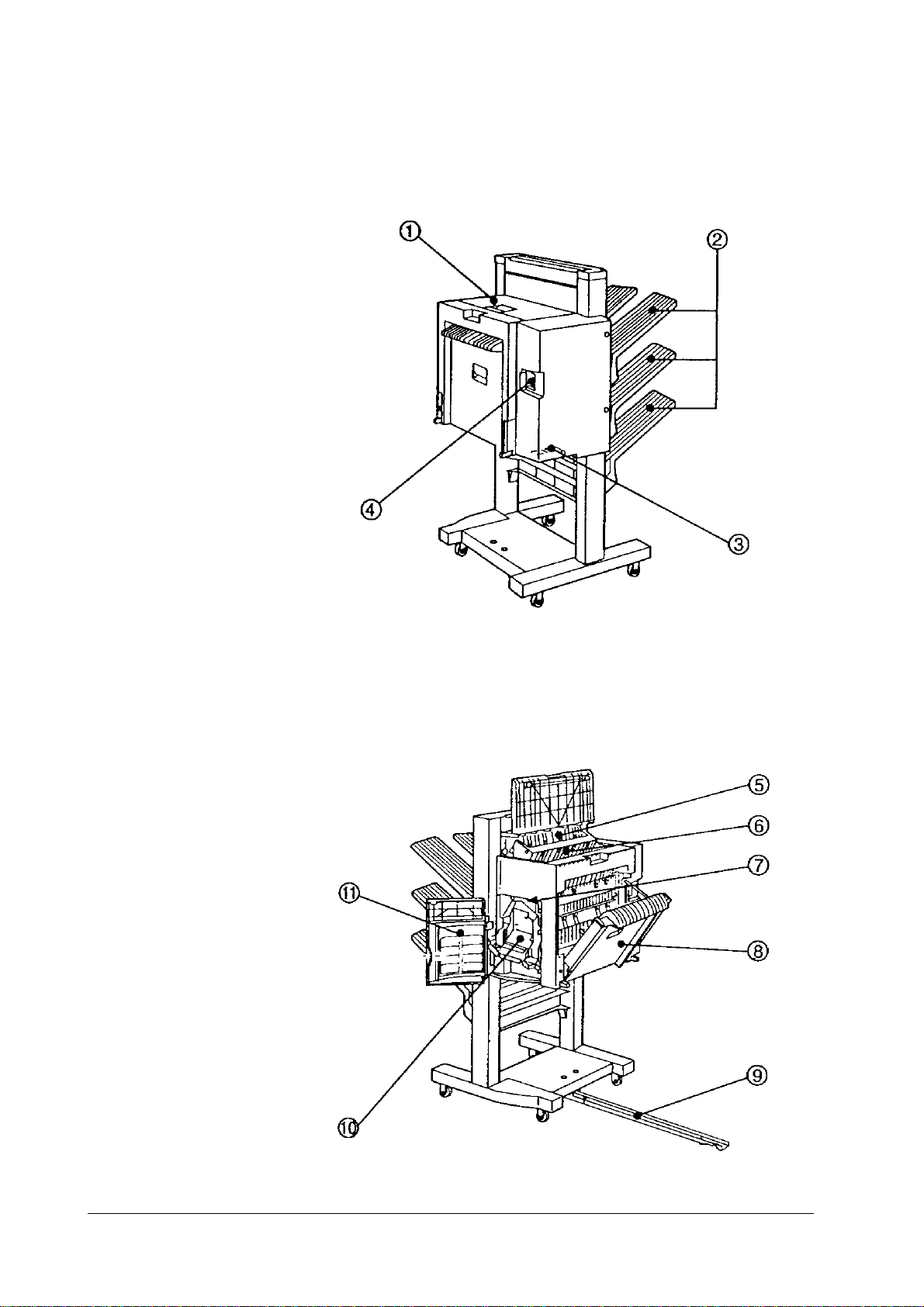
External diagram
DF-30/DF-31
1-5
Page 9

Table 1.2 External Component
FEATURES
Part names
Item (See
above)
1
2
3
4
5
6
7
8
9
10
11
Component
Upper door
Trays
Interface connector
Power supply receptacle
Upper guide
Lower guide
Staple reset switch (Not used)
Right side cover
Guide rail
Staple unit
Front door
1-6
Page 10
FEATURES
Part names
Internal Compone n t
Table 1.3 Internal Component
Item (See
above)
1
2
3
4
5
6
7
8
Trays
Shutter
Swing guide
Distance sensor
Paddle
Inversion roller
Staple unit
Tray elevation motor
Component
DF-30/DF-31
1-7
Page 11

1.1 Installation
Precautions during installation
All important adjustments were made to this equipment prior to it being packed
and shipped from the fa ctor y, and it has als o bee n su bj ect to a thoroug h i nsp ect ion.
The installation procedure is extremely important to ensure that the equipment
performs mechanically in accordance with the ratings acquired during the inspection process after it has been unpacked by the customer.
The service engineers must therefore have a full understa nding of the mechanical
capabilities of this equipment, and it must be installed in a favorable environment
in accordance with correct procedures.
Location of installation
Ensure that the location of installation satisfies the following conditions. It is recommended that an area that meets these conditions is determined prior to the unit
being delivered to the customer.
Power supply
FEATURES
Installation
Prepare a power supply that conforms to the following:
•
Current (AC)
•
Supply frequency
Operating environment
Ensure that the location of installation conforms to the following:
A flat and horizontal surface
•
Temperature and humidity ranges must be within the following:
•
•
Surrounding temperature
•
Surrounding humidity
tion
Areas which are well-ventilated and not subject to steam.
•
• Avoid installation in the following locations.
Areas where the device will be subject to direct sunlight.
•
If this is unavoidable and the device must be installed in an area where it is subject
to direct sunlight, ensure that a thick curtain or other form of protection is used to
deflect the sunlight.
Areas near magnets or wher e magnetic fields exist.
•
Areas that are subject to vibrations.
•
Areas in which dust collects.
•
Near to open flames and moisture.
•
. Rated current ±10%
. 50/60Hz ±2Hz
. 10 to 32.5 degrees Celsius
. 20 to 80% RH (relativ e humidity ) without cond ensa-
1-8
Page 12
FEATURES
Installation
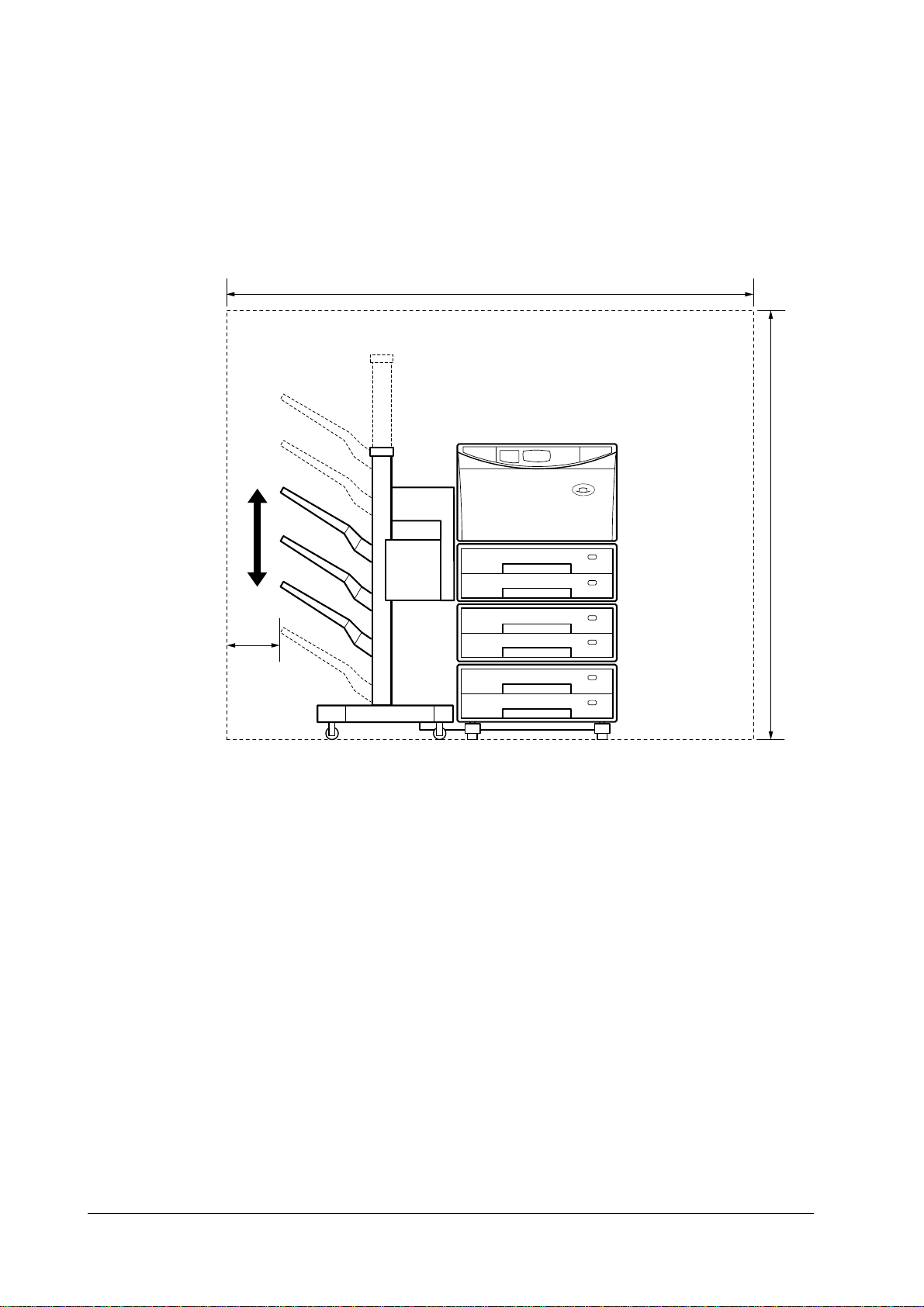
Installation space
Install the device at a suitable distance from walls and other obstructions, and
secure enough space to enable easy operations.
Figure 1.1
Installation space
2680 mm
1380 mm
630 mm
Procedures for unpacking and installation
There are cases where water droplets will form on the surface of metal fittings
when brought into warm places from cold places. This is known as condensation,
and using equipment on which condensation has formed may result in faults arising with the feeder assembly. To avoid this, do not unpack the device for at least
one hour after it has been brought in from a cold place to allow it to become accustomed to room temperature.
Unpacking the finisher
Remove the outer box in which the finisher is packed.
1
Remove the accessories. Confirm that the accessories include the power sup-
2
ply cord, the manual, the guide rails, the trays, the earth adapter and the
interface cable.
Remove the upper pads (left and right) and lift the finisher out of the box.
3
Remove the vinyl bag in which the finisher is packed and then peel off the
4
tape that holds each part in place. Verify that the covers were not scratched,
bent or otherwise damaged during transportation.
Open the front cover and remove the two spacers.
5
Attach the trays to the finisher with the screws.
6
DF-30/DF-31
1-9
Page 13
1.2 Removing paper jams
When jams occur, removing the jammed paper from the inside of the machine in
accordance with the following procedures.
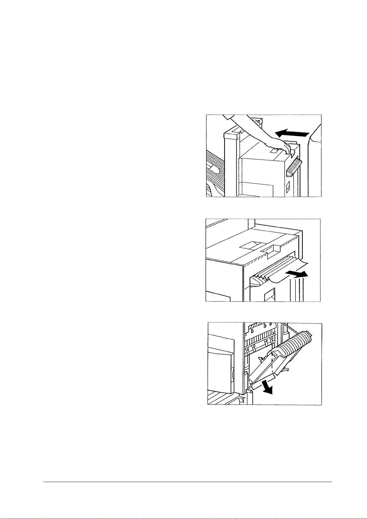
Paper jammed in the inversion assembly
Separate the finisher from
1
the printer.
FEATURES
Removing paper jams
Remove any jammed paper
2
that can be se en.
If the jammed paper cannot
3
be removed, open the inversion cover assembly and
remove the jammed paper
then.
1-10
Page 14

FEATURES
Removing paper jams
DF-30/DF-31
1-11
Page 15
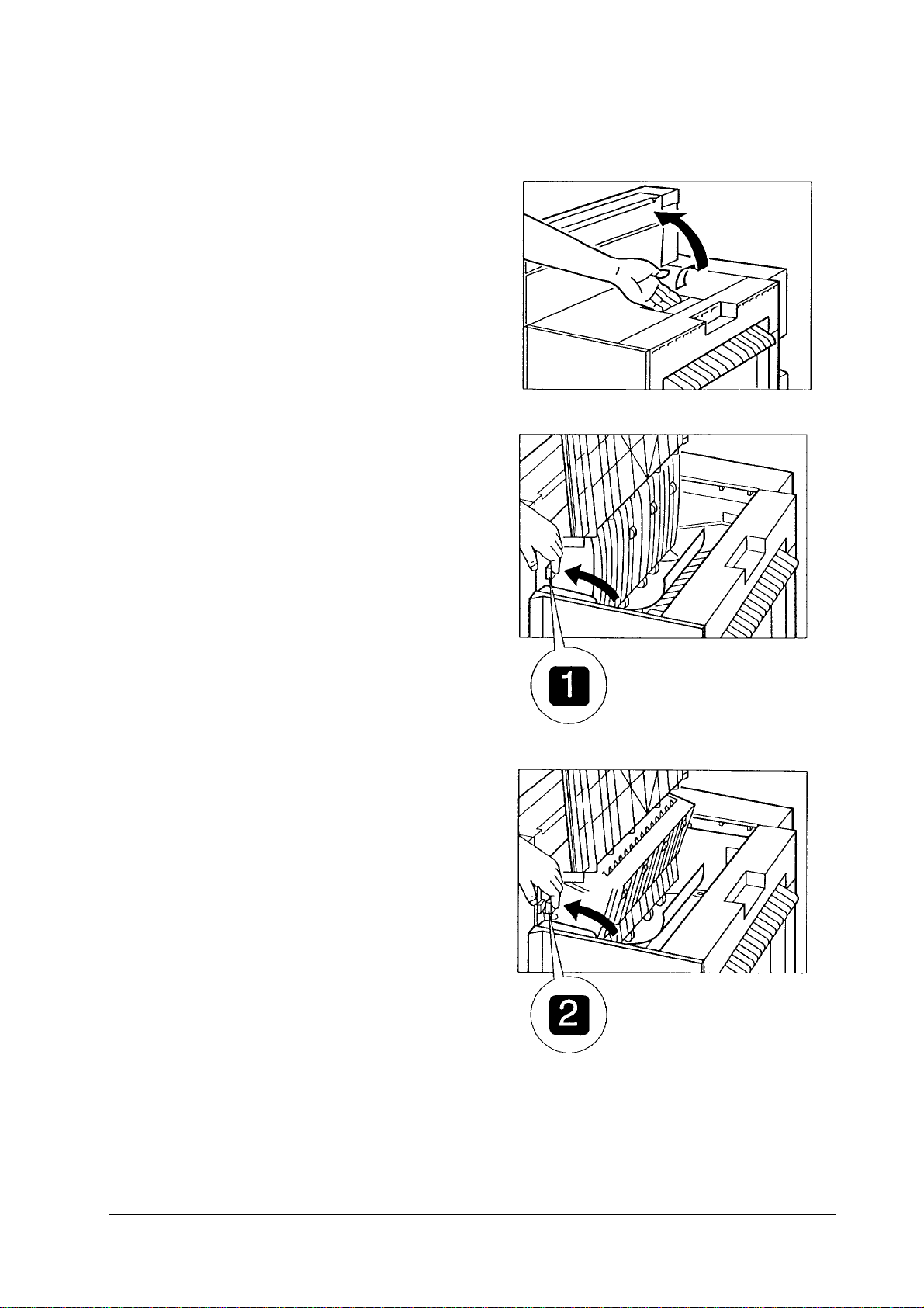
Paper jammed in the feeder assembly
Open the top cover.
1
Grip the knob and open the
2
upper guide.
Remove any jammed paper
3
that can be se en.
If the jammed paper cannot
4
be removed, grip the knob
and open the lower guide.
FEATURES
Removing paper jams
Remove any jammed paper
5
that can be se en.
1-12
Page 16
FEATURES
Removing paper jams
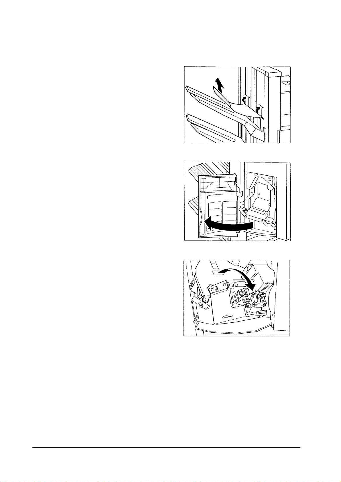
Paper jammed in the paper ejection assembly
Raise the paper guid e and
1
remove any jammed paper.
Open and close the front
2
cover, the upper cover and
the inversion cover.
Staples jammed in the Staple
assembly
Open the front cover.
1
Pull out the staple assembly.
2
DF-30/DF-31
1-13
Page 17
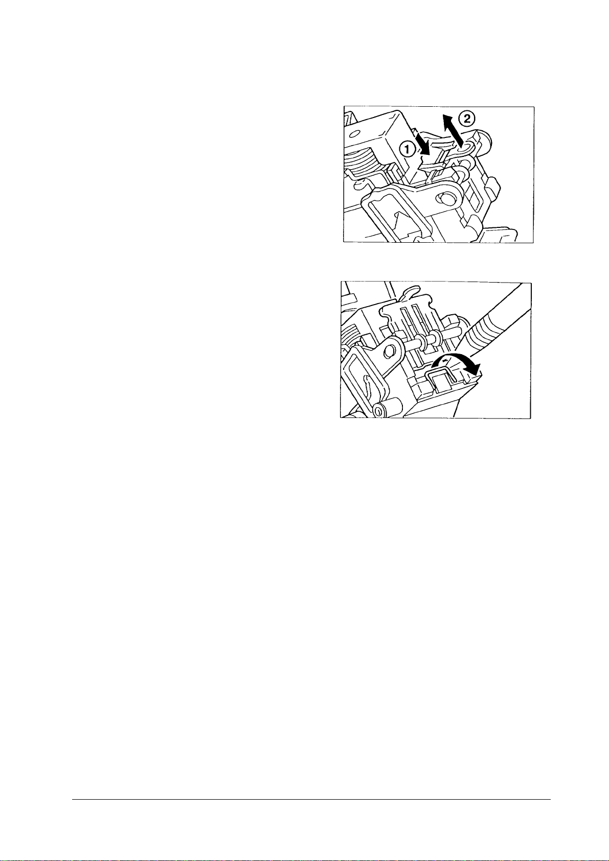
Grip the knob while apply-
3
ing pressure to the green
lever (¨) and pull out the
Staple guide.
Remove the jammed staple
4
with a poin ted object.
Grip the knob and replace
5
the staple guide.
FEATURES
Removing paper jams
1-14
Page 18
FEATURES
Customer maintenance and inspections
1.3 Customer maintenance and inspections
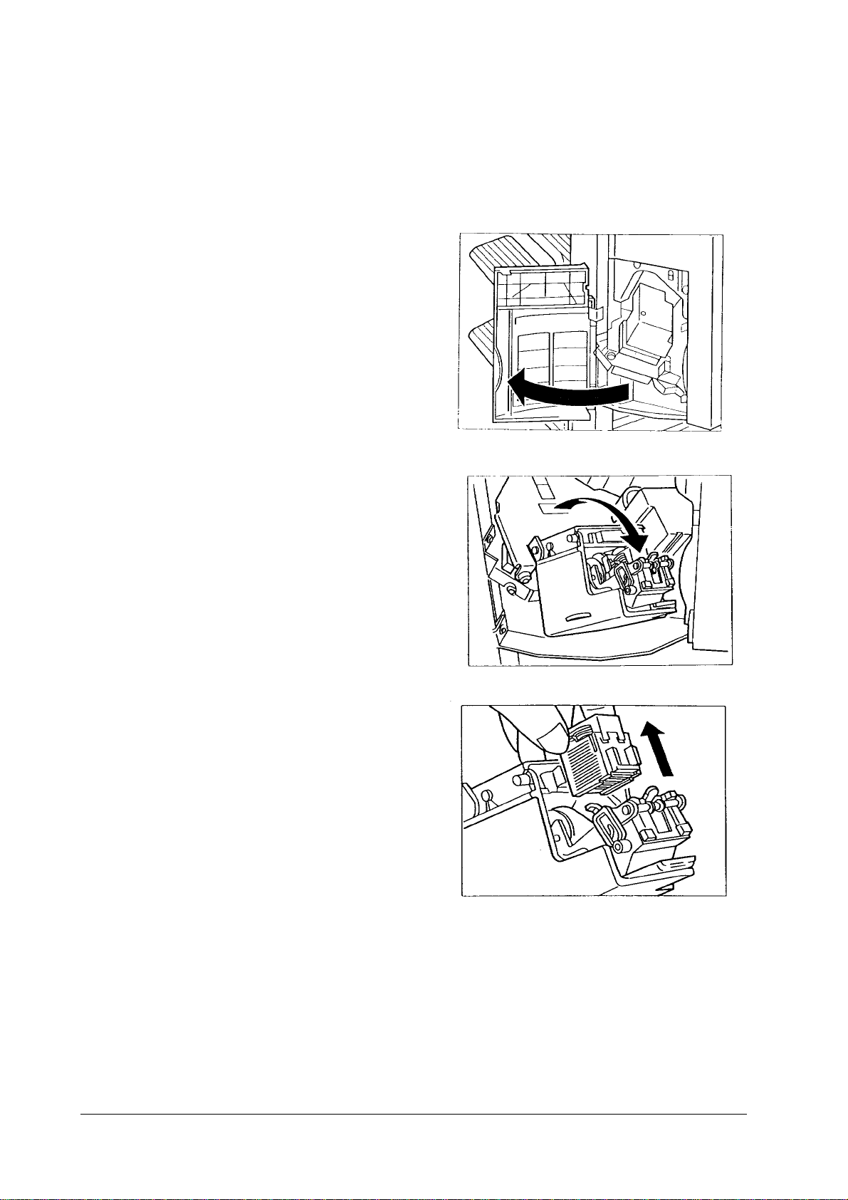
Replacing the staple cartridge
Replace the staple cartridge in accordance with the following procedure.
Open the front cover.
1
Pull out the staple assembly.
2
Remove the staple cartridge.
3
DF-30/DF-31
1-15
Page 19

Insert the staple cartridge
4
until it catches on the clip.
Return the staple assembly
5
to its original position.
FEATURES
Customer maintenance and inspections
1-16
Page 20

FEATURES
Customer maintenance and inspections
DF-30/DF-31
1-17
Page 21

Chapter 2 OPERATION THEORY
Contents
General 2
Basic operations 3
Outline 3
Outline of electrical circuits 3
Finisher driver input/output 5
Feed and drive systems 9
Outline 9
Face-down paper ejection 1 0
Normal stacking 10
Job offset 10
Stapling 11
Face-up paper ejection 12
Normal stacking 12
Feeding and ejection 13
Outline 13
Face-down feeder (inversion operations)/paper ejection operations 16
Face-up feeder, paper ejection operations 16
Job offset 16
Staple operations 18
Outline 18
First page operations 19
Second and subsequent page operations 21
Last page operations 22
Tray operations 23
Stapler unit 25
Tray loading volume detection 26
Stacking mode details 26
Jam detection 27
Power supply 30
Outline 30
Protection functions 30
Page 22

OPERATION THEORY
General
2.1 General
This chapter provides explanations on the purpose, role and mechanical system of
each function, as well as providing an outline of the operational timing of each part
by function.
The descriptions of the digital circuits for this device include signals names without slashes (“/”) for H and PSNS electrical signal levels, and signal names with
slashes, such as L and /SCNON.
H and other signal names without slashes (“/”) are true (indicating that the signal
has been output) at the supply voltage level and false (indicating that the signal
has not been output) at the G ND leve l. L and other s ignal s name s wit h sla she s are
true at the ND level and false at the supply voltage level.
This device uses a microcomputer. However, as it is impossible to run an internal
operation check on a microcomputer, the explanation for the microcomputer operations has been omitted.
Also, as it is a pre-requisite for the internal printed circuit board to be untampered
with by the customer, simple summaries with the use of block diagrams have been
used in this manual to cover the descriptions of these printed circuit boards. Owing
to this, the explanations for circuits only cover the two areas from the sensors to
the input areas of the main substrates and from the output area of the main substrates to the load, and block diagrams are used to explain each function.
DF-30/DF-31
2-2
Page 23
2.2 Basic operations
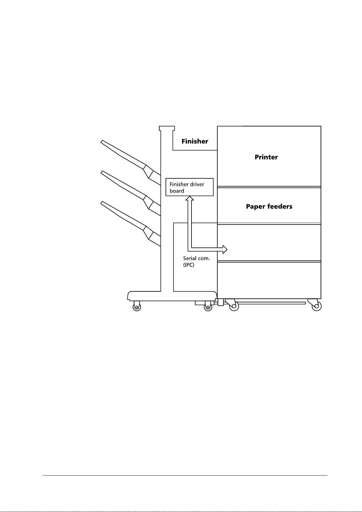
Outline
The finisher performs the face-down ejection and face-up ejection of paper fed
through from the printer. The job offset and stapling functions are available with
face-down ejection.
These operations are controlled by the finisher driver’s circuit board.
OPERATION THEORY
Basic operations
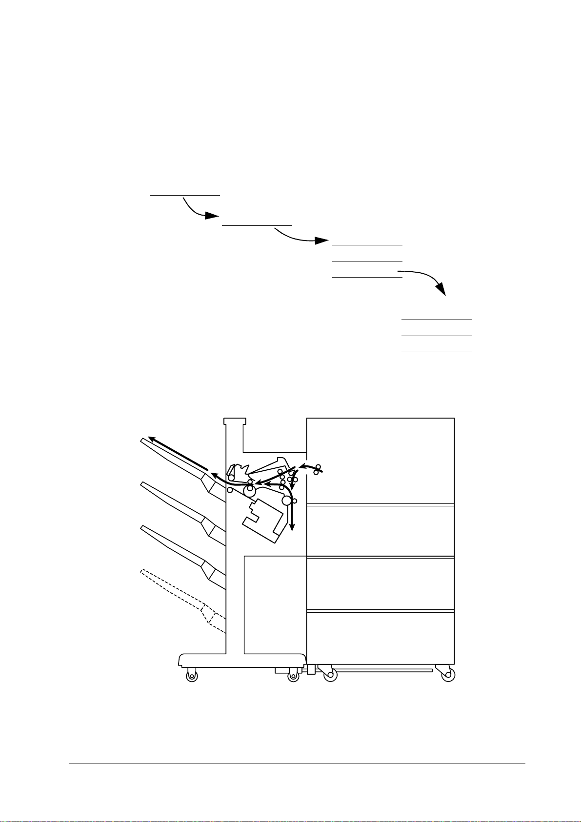
Figure 2.1
Outline of the finisher
Outline of electrical circuits
The finisher’s operational sequence is controlled by the finisher driver’s circuit
board. A 16-bit microcomputer (CPU) is used in the finisher driver’s circuit board,
and this performed serial communications with the sequential control.
The finisher driver operates the solenoids and motors, etc., in accordance with the
various commands that are transmitted from the option controller via the serial
communications line. The finisher driver also notifies the option controller of sensor and switch information via the serial communications line.
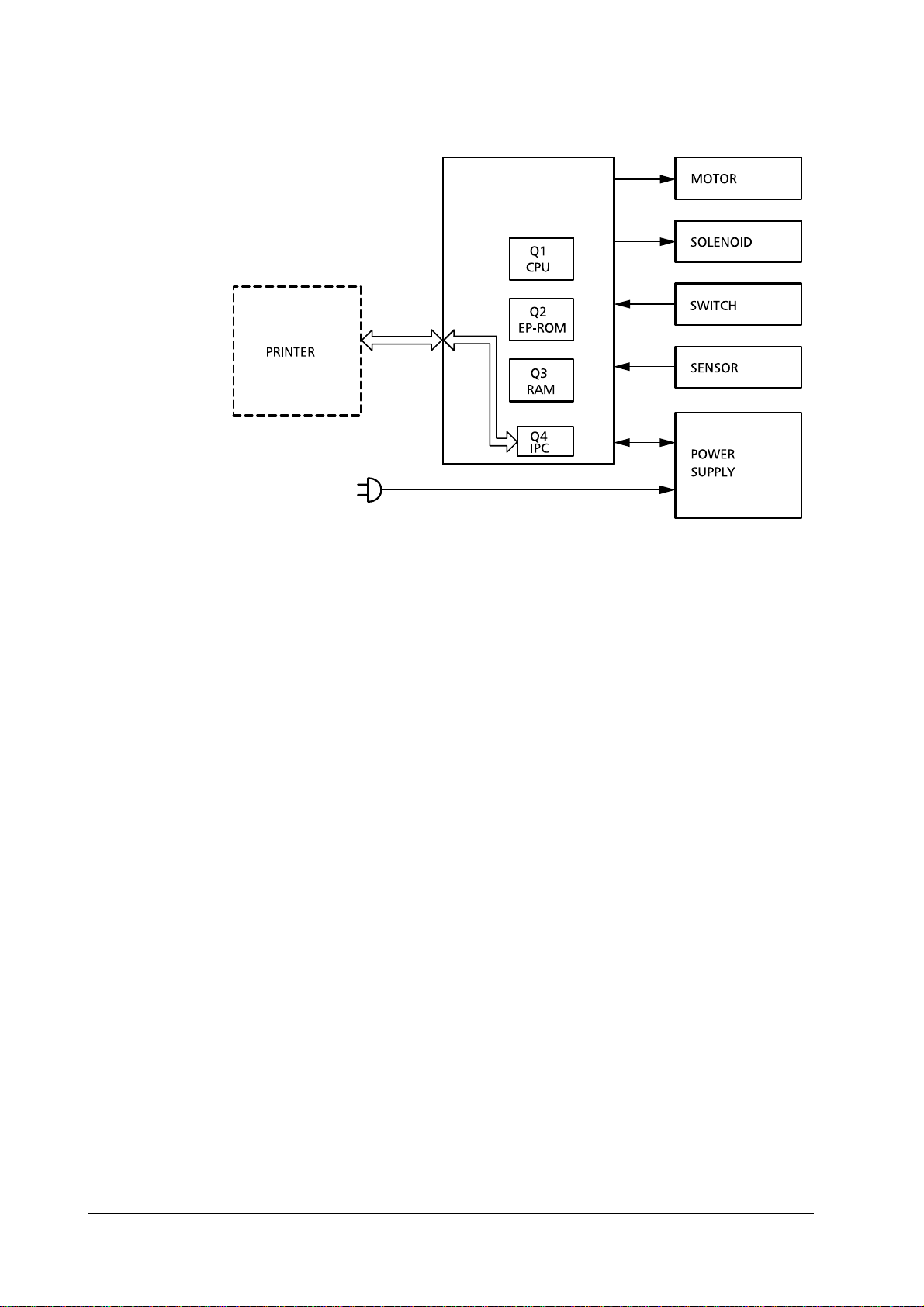
The major roles of the ICs mounted in the finisher driver are as follows.
Q1 (CPU). Sequential control.
•
Q2 (EP-ROM). Sequential programs built in.
•
Q3 (RAM). Used for backing up the initial data.
•
Q4 (IPC). Used for communications control.
•
The diagram below shows the signal flow between the finisher and the printer.
2-3
Page 24
OPERATION THEORY
Basic operations
Figure 2.2
Signal flow between the finisher and the printer
DF-30/DF-31
2-4
Page 25
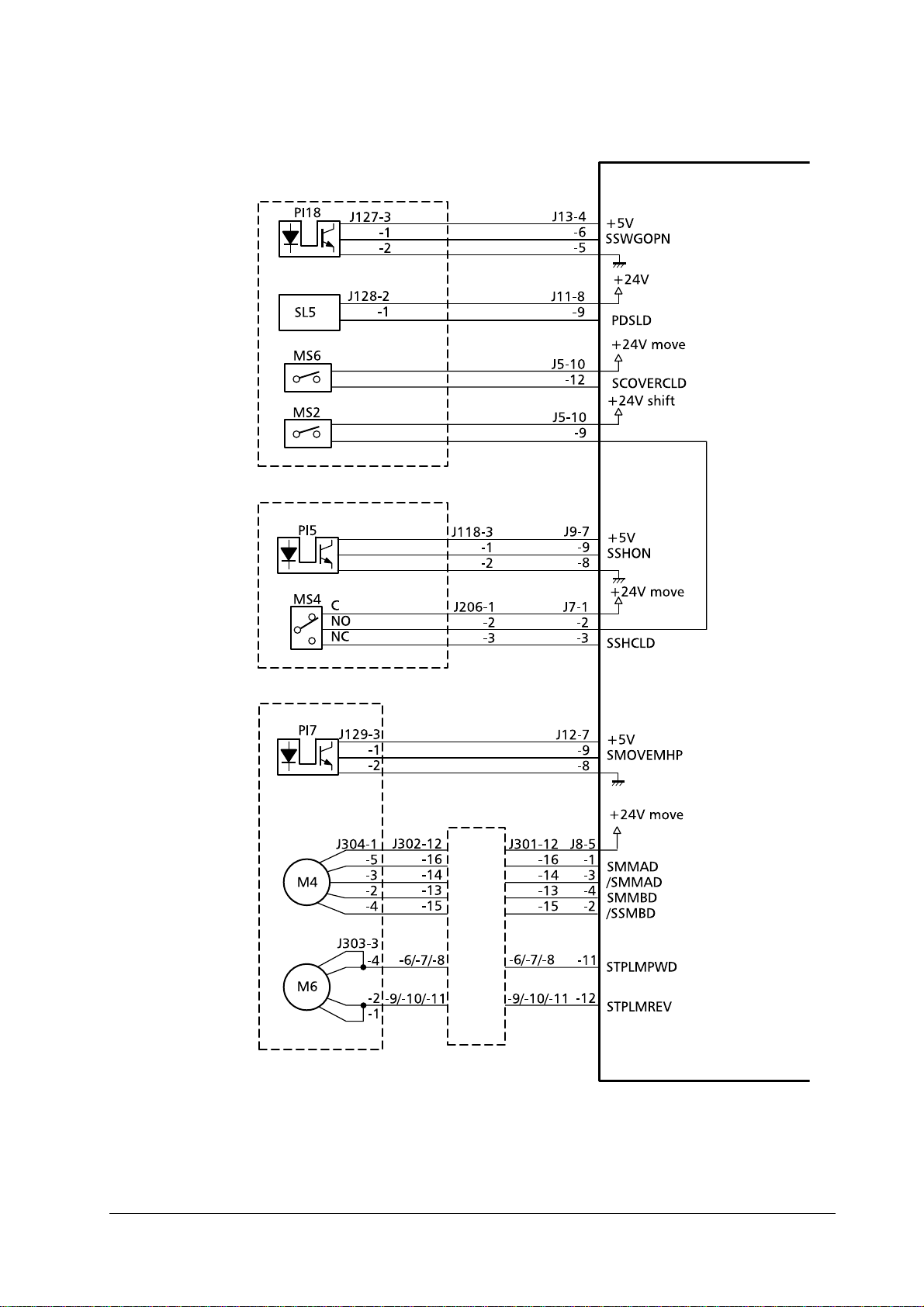
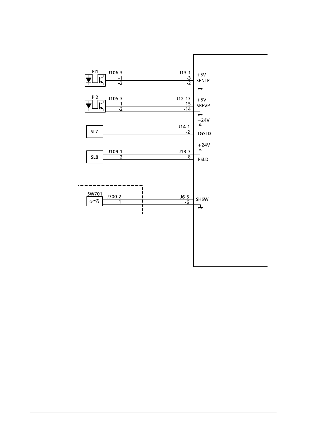
Finisher driver input/output
OPERATION THEORY
Basic operations
Staple tray paper
detection sensor
Matching board
home position
detection sensor
Paper ejectio n
detection sensor
Base board
shelter solenoi d
Matching board
movement mo tor
Staple tray assembly
Finisher driver circuit board
"L" when the sensor
detects paper.
"L" when the sensor
detects the matchi n g
board’s home position.
"L" when the sensor
detects paper.
The base board is
sheltered when "L".
Control signals for
the matching board
movement mo tor
Paper ejection
motor clock
detection sensor
Paper ejection
motor
Pulse emitted in
accordance with the
revolution speed of
the ejection motor
Control signals for
the paper ejection motor
2-5
Page 26
OPERATION THEORY
Basic operations
Frame assembly
Joint sensor
Tray elevation
motor clock
detection sensor
Distance sensor
Tray elevation
motor temperature sensor
Tray elevation
motor
Top cover open/
close detection
switch
Front cover open/
close detection
switch
Tray home position detection
sensor
"L" when connected to the
printer.
Pulse emitted in
accordance with
the revolution
speed of the tray
elevation motor.
Control signal for
the distance sensor
"L" when the
temperature of
the tray elevation
motor is high.
Control signals for
the tray elevation
motor.
"L" when the sensor detection the
tray’s home position.
Safety area
detection switch
Tra y uppe r limit
detection switch
Feeder motor
Control signal for
the feeder mot o r.
DF-30/DF-31
2-6
Page 27
OPERATION THEORY
Basic operations
Swing guide
assembly detection sensor
Paddle drive solenoid
Swing guide
open/close detection switch
Swing guide
open/close detection switch
Shutter close
detection sensor
Shutter open
detection sensor
Swing guide assembly
Shutter guide assembly
Finisher driver circuit board
"L" when the
swing guide is
open.
Paddle revolves
when "L".
"H" when the
shutter is
closed.
"H" when the
shutter is closed
Stapler home
position detection sensor
Intermediate circuit board
Stapler move ment motor
Staple motor
Staple unit
"L" when the stapler’s home position is detected.
Liaision
board
Control signals for
the stapler movement motor.
Control signals
for the stapler
motor
2-7
Page 28
OPERATION THEORY
Basic operations
Finisher driver circuit board
Inlet paper
detection sensor
Inversion paper
detection sensor
Inversion roller
drive solenoid
Face-up flapper
solenoid
Staple exchange
completion
switch
"L" when the sensor detects
paper.
"L" when the sensor detects
paper.
Inversion roller
revolved when
"L".
Paper fed face-up
when "L".
Staple exchange completion
switch circuit board
Staple operations
started when "H".
DF-30/DF-31
2-8
Page 29
OPERATION THEORY
2.3 Feed and drive systems
Outline
This device stacks, shifts, staples and ejects paper to the tray in accordance with
the commands transmitted from the printer.
The four different methods of paper ejection are explained below.
Paper ejection methods
Face-down ejection
Feed and drive systems
Normal stacking
Job offset
Staple
One on the left-hand side
One on the right-hand side
Two in the center
Figure 2.3
Feed and drive sys tem
2-9
Page 30

OPERATION THEORY
Feed and drive systems
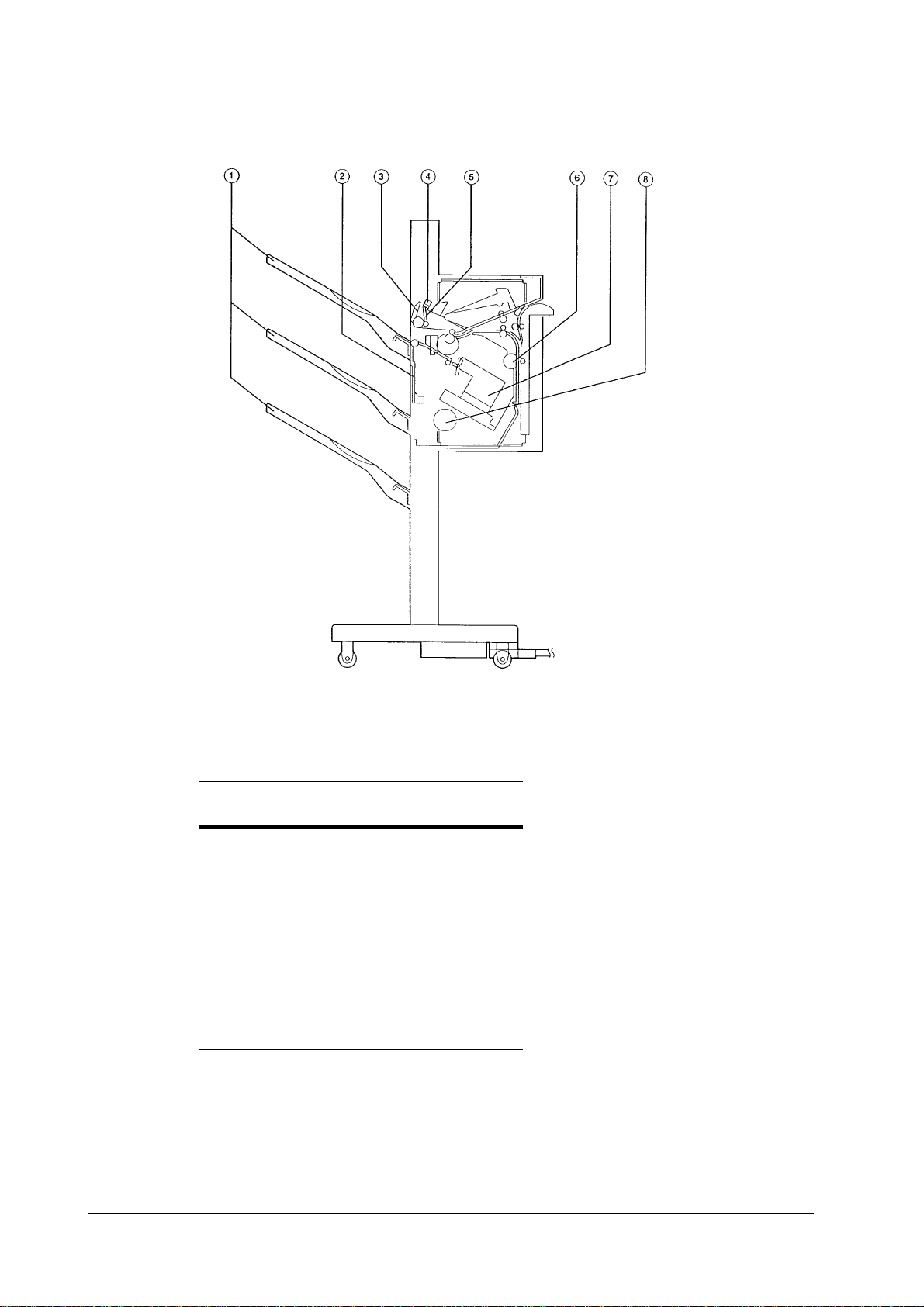
Face-down paper ejection
Normal stacking
The paper is ejected to the tray face down after being inverted.
Tray
Printed output
Top guide
Face-up tra nsport
roller
Eject roller #1
Eject roller #2
Bottom guide
Tr ansport roller #2
Face-up
diverter
Transport
roller #1
Job offset
The job offset operates in two ways: First-page-only mode and whole-set-of-pages
mode.
In the first-page-only mode, the first piece of paper is inverted and fed through to
the staple tray . The piece of paper is then shifted forward by approximately 30mm,
and ejected face down to the tray.
The second and subsequent pieces of paper are inverted and ejected to the tray
without being fed into the staple tray.
DF-30/DF-31
•
First page
Tray
Swing guide
Paper ejection roller #1
Stopper
Feed roller #2
Paper ejection
roller #2
Staple tray
2-10
Page 31

•
Second and subsequent pages
Tray
Second and subsequent pages
First page
Swing guide
OPERATION THEORY
Feed and drive systems
Paper ejection roller #1
Tray
Stopper
Staple tray
Feed roller #2
In the whole set of pages mode (defa ult), the whole page of a print jo b is fed into the
staple tray so that the jop is shifted forward. The subsequent job as a whole is not
shifted but delivered in a normal manner, allowing every other job is shifted to
each other.
Stapling
The pages are inverted, stacked in the staple tray, stapled and then ejected to the
tray.
Tray
Paper
Staple
Swing guide
Tray
Stopper
Staple tray
2-11
Page 32

OPERATION THEORY
Feed and drive systems
Figure 2.4
One staple on the le ft-hand side (1)
One staple on the right-hand side (2, angled)
Positions of stapling
Paper width/2
Two staples in the center (3)
One staple on the right-hand side (2, horizontal)
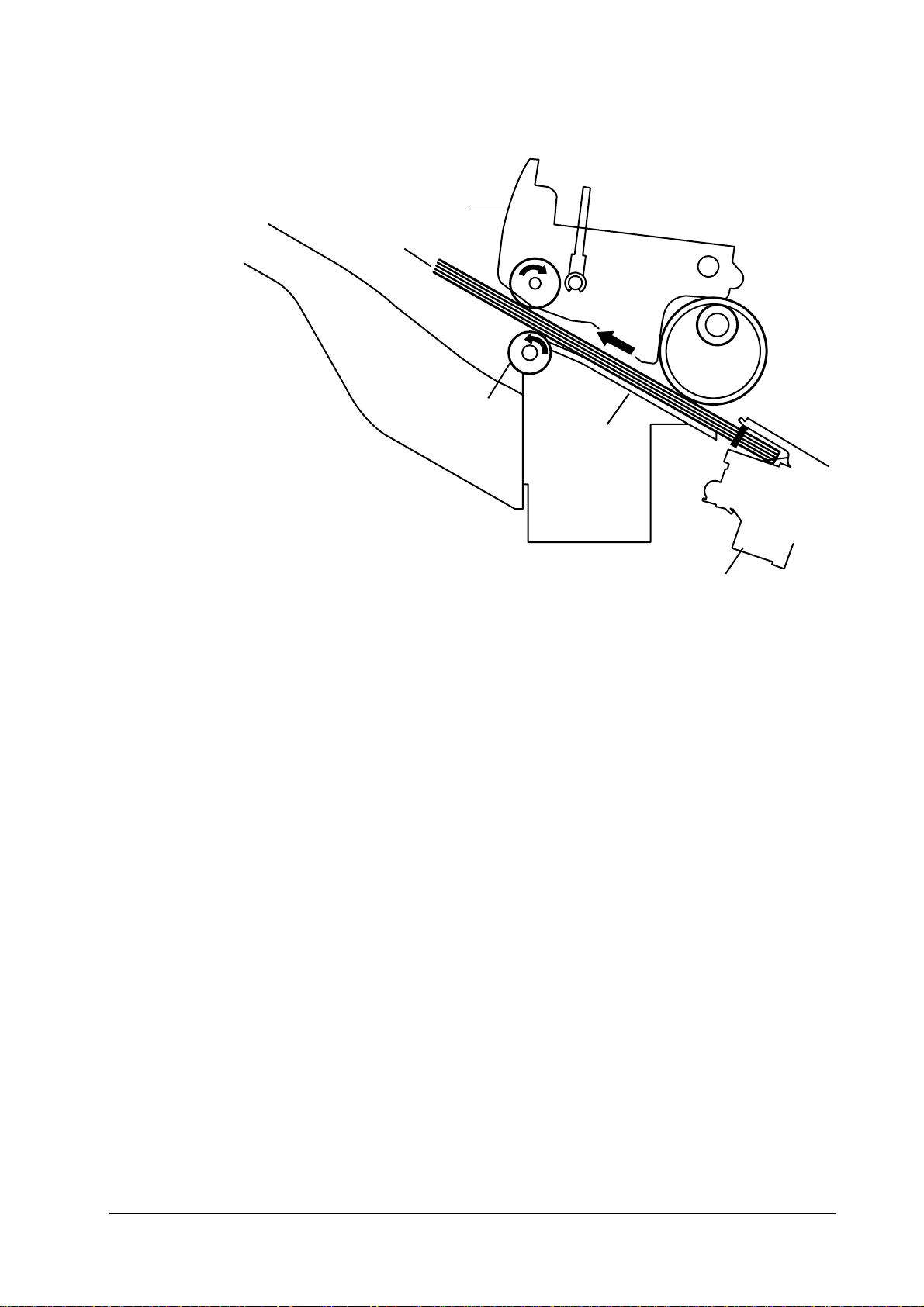
Face-up paper ejection
Normal stacking
The paper is ejected face-up to the tray without being inverted.
Tray
Paper
1
2
3
Upper guide
Paper ejection roller #1
Paper ejection roller #2
Face-up feed roller
Lower guide
Test staples (Not used)
Feed roller #2
1
2
3
Face-up
diverter
Feed roller #1
DF-30/DF-31
Inversion roller
2-12
Page 33

OPERATION THEORY
Feed and drive systems
Feeding and ejection
Outline
When the paper fed through from the printer is to be laid face down in the tray, the
inversion operation is performed.
The feed motor (M1) is a stepping motor, and the paper ejection motor (M2) is a DC
motor. The forward and reverse operation for these motors is controlled by the
microcomputer (CPU) in the finisher driver’s circuit board.
Three photo-interrupters, the inlet paper detection sensor (P11), the inversion
detection sensor (P12) and the paper ejection detection sensor, are situated along
the paper’s feed route, and these check whether the paper has reached its destination or is still in transit.
The finisher driver will judge that a paper jam has occurred if the paper does not
reach or pass each sensor within a pre-determined period of time. In this event,
operations are halted and notification of the jam is sent to the printer.
2-13
Page 34

OPERATION THEORY
Feed and drive systems
Finisher driver circuit board
Table 2.1 Detection signals
(1)
(2)
(3)
(4)
(5)
PS1:
PI1:
P12:
P13:
P14:
DF-30/DF-31
Staple tray pap er detection signal
T ray stacking volume dete ct ion signal
Paper ejection detection signal
Inverted paper detection signal
Inlet paper detection signal
Distance senso r
Inlet paper detection sensor
Inverted paper detection sensor
Paper ejection detection sensor
Staple tray paper detection sensor
2-14
Page 35

OPERATION THEORY
Finisher driver circuit board
Feed and drive systems
Table 2.2 Motors/solenoids— (1 / 2)
M1:
M2:
M3:
M4:
M5:
SL5:
SL7:
SL8:
(1)
(2)
(3)
2-15
Feed motor
Paper ejection motor
Matching board’s movement motor
Stapler movement motor
Tray elevation motor
Paddle drive solenoid
Inversion roller driver solenoid
Face-up flapper drive solenoid
Stapler movement motor drive signal
Tray elevation motor drive s ignal
Matching board movement motor drive signal
Page 36

OPERATION THEORY
Feed and drive systems
Table 2.2 Motors/solenoids— (2 / 2)
(4)
(5)
(6)
(7)
(8)
Paper ejectio n m o to r dr ive signal
Paddle solenoid drive signal
Feed motor drive signal
Inversion solenoid drive signal
Face-up flapper solenoid drive signal
Face-down feeder (inversion op erations)/paper ejection operations
The feeder motor (M1) and paper ejection motor (M2) are started up when the finisher driver receives a paper ejection signal from the printer, and feeder roller #1,
feeder roller #2, paper ejection roller #1 and paper ejection roller #2 are put into
motion. By starting up fee der ro lle r #1 , a si ngle s heet of pap er is t rans fe rred t o the
inverter . A paper detection s ensor (P11) located at the inlet detects the bottom edge
of the paper, and after transferring it to the prescribed position, the inversion roller
driver’ s solenoid (SL7) is activated and the M1 driver starts up the inversion roller.
This conveys the paper through to an inverted position. On ce the paper has been
inverted, it is passed through to the feeder guide by the inversion roller operating
in the reverse direction. The paper is then fed and ejected by feeder roller #1,
feeder roller #2, paper ejection roller #1 and paper ejection roller #2.
Face-up feeder, paper ejection operations
When the paper trans ferred fr om the printer t o the tray is to b e ejec ted face up, the
feeder motor (M1) and th e paper ejecti on motor (M2) a re put into mo tion by a p aper
ejection signal received by the finisher driver from the printer, and the face-up
feeder roller, paper ejection roller #1 and pap er e jecti on ro ller #2 are st ar ted up. At
the same time, the face-up flapper driver solenoid (SL8) is activated, and the flapper is switched across to the face-up side. This enables the paper to be fed and
ejected without being inverted.
Job offset
Shift operations move only the first piece of p aper or whole set of paper (default) fo r
each job, and eject the second and subsequent pieces of paper without moving
them.
The paper is moved with the matching board, and the matching board home position detection sensor (P16) detects whether this board is at the home position or
not.
The matching board movement motor (M3) is activated when the power supply is
switched on in order for the finisher driver to return the matching board to the
home position. If the matching board is already in the home position, the system
enters the stand-by mode. As the distance for moving the matching board is
extended when paper other tha n A3 and A4 (horizonta l) is us ed, the fi nisher dr iver
moves the matching board to the stand-by position.
1
The finisher driver hal ts the operation of the paper ejection motor (M2) after the
first piece of paper has passed the far end of paper ejection roller #1. The gear is
1. The stand-by position is 5mm outside of the paper’s edge.
DF-30/DF-31
2-16
Page 37

OPERATION THEORY
Feed and drive systems
then moved to the swing guide drive assembly after the M2 motor has been put into
reverse. This transmits the operation of M2 across to the gear and raises the swing
guide. The swing guide is raised until it is detected by the swing guide open detection sensor (PI18) and then halted.
The paper is returned to the staple tray by the rubber surface fitted to paper ejection roller #1 when the sw ing gui de is rais ed. Th e paper retu rned to the st aple tray
is then detected by the staple tray paper detection sensor (PI4).
The matching board movement motor (M3) is then activated and the paper moved
by 30mm. Depending on the size of the paper, there are cases where it cannot be
moved by 30mm as it will interfere with the left-hand edge. In this event, the base
board shelter solenoid (SL6) is set at ON, and the paper is moved 30mm after the
left-hand base board has been sheltered.
The finisher driver activates M3 in the reverse direction and moves the matching
board to the stand-by position after the paper has been moved.
The finisher driver then activates M2 in the reverse direction to lower the swing
guide. M2 is run in the forward direction when the swing guide open/close detection switch (MS2) is set at ON, and paper ejection roller #2 is activated. This ejects
the paper to the tray. The second and subsequent pieces of paper for each job are
ejected to the tray without shift movement.
Left-hand base board
Base board shelter solenoid
Matching
board
Matching board
home position
detection sensor
Matching board
movement motor
Paper
For information on modes of stapling available, see page 2-12.
2-17
Page 38

OPERATION THEORY
Feed and drive systems
Staple operations
Outline
The staple operations staple together a specified quantity of paper in the stapler
unit.
The position of the staples will differ in accordance with the stapler motor and the
size of the paper. Refer to table 2-2-1 for further details.
The stapler home position detection sensor (PI7) detects whether the stapler unit is
at the home position or not.
The finisher driver activates the stapler movement motor (M4) after receiving the
start signal from the printer, and moves the stapler unit to the central stand-by
position (note).
Note
Table 2.3 Positions of staples
The central stand-by position is the location where the stapler unit is situated prior to the
paper being returned to the stapler tray in order to prevent the stapler operations being rendered impos sible owing to the paper curling up inside the staple t r ay.
Staple mode A3 A4R
One, on left-hand side
One, on right-hand side
Two, centered
Test (Not used)
Refer to page 12, table 2.4 on (1) to (5) for details.
B5/
B4
(2) (3)
(4)
Ldg
(1)
(5)
Ltr/
Ltr A4 Lgl Otrs
R
DF-30/DF-31
2-18
Page 39

Stapler home
position sensor
OPERATION THEORY
Feed and drive systems
Paper
Stapler
movement
motor
Stapler unit
First page operations
The finisher driver halts the operation of the paper ejection motor (M2) after the
first piece of paper has passed the far end of paper ejection roller #1. The ge ar is
then moved to the swing guide drive assembly after the M2 motor has been put into
reverse. The swing guide is raised by M2 until it is detected by the swing guide
open detection sensor (PI18) and then halted. The paddle drive solenoid is then set
at ON, and the feed motor drive operates the paddle.
The paper is returned to the staple tray by the rubber surface fitted to paper ejection roller #1 when the swing guide is opened where it is detected by the staple tray
paper detection sensor (PI4).
The matching board movement motor (M3) is activated and the pieces of paper are
matched up.
2-19
Page 40

OPERATION THEORY
Feed and drive systems
Swing guide
Swing guide open
detection sensor
Swing guide open
detection switch
Paper ejection
roller #2
Swing guide
Fist page of paper
Paper ejection
roller #2
Tray
Feed m otor cl ock
detection sensor
Paper eject io n motor
Paper ejection roller #1
Rubber roller
Staple tray
DF-30/DF-31
Stapler unit
2-20
Page 41

OPERATION THEORY
Feed and drive systems
Second and subsequent page operations
The finisher driver halts the operation of the paper ejection motor (M2) when the
bottom edge of the second and subsequent pieces of paper have passed 20mm
through paper ejection roller #1. The paddle drive solenoid is then set at ON, and
the feed motor (M1) drive ope rates the paddle. This returns the pa per to the s tapler
tray, activates the matching board movement motor (M3) and matches up the
pieces of paper.
Paddle
Paddle driver
solenoid
piece of pape r
Second and subsequent
pieces of paper
Swing guideSecond or the subsequent
First piece of paper
Stopper
Stapler unit
Paddle
Paper ejection roller #1
Rubber roller
Tray
Paper ejectio n
roller #2
Staple tray
Stapler unit
2-21
Page 42

OPERATION THEORY
Feed and drive systems
Last page operations
The finisher driver sta rts up M3 once again after the matching process has been
completed for the last piece of paper in order to move the matching board to the
staple matching position (note #1). The multiple sheets of paper are then matched
up and the motor halted. The finisher driver then activates M2 in the reverse direction and lowers the swing guide.
The finisher driver activates the stapling process in accordance with the specified
staple mode transmitted from the printer (refer to fig.2-2-12 on page 2-19) and staples the pages together.
The finisher driv er activat es M3 when t he stapli ng process has been completed an d
moves the matching bo ar d to t he shel ter p osi ti on ( not e #2 ) whe n t he p aper i s being
ejected. The paper ejection mot or (M2) is then ac tiva ted i n the forwa rd dir ectio n to
operate ejection ro ller #2 and eject th e stapled pages to the tray.
Swing guide
Note
Paper ejection roller #2
Paper ejection motor
1. The staple matching position is 0.5mm inside the horizontal width of the paper. 2. The shelter position during paper ejection is 5.0mm outside of the horizontal width of the paper.
DF-30/DF-31
2-22
Page 43
Swing guide
Paper
Paper ejection
roller #2
OPERATION THEORY
Feed and drive systems
Staple tray
Stapler unit
Tray operations
The finisher driver is equip ped wit h three trays , and pa per can be eject ed to ei ther
of these trays. The trays are moved upwards and downwards with the tray elevation motor (M5). The position of each tray is detected by the tray elevation motor
clock detection sensor (PI9) with the amount of encoder pulses fitted to M5. The
tray home position detection sensor (PI8) detects whether the trays are at their
home positions or not.
2-23
Page 44

OPERATION THEORY
Feed and drive systems
Tr ay #1
Tr ay #2
Tray guide
T r ay upp er lim it detection
switch
Tr ay #3
Tray elevation motor
Safe area detection switch
The finisher driver raises and lowers the tray guide until it is aligned with the
paper ejection outlet specified by the printer.
The upper limit for the tray is detected by the tray upper limit detection switch
(MS5). The tray elevation motor (M5) is halted when the finisher driver sets MS5
to ON.
Tray elevation motor clock
detection sensor
Encoder
Tray home position sensor
DF-30/DF-31
The height of the paper eje c ted t o t he tray i s detect ed by t he d ista nce se nsor (PS1 ).
The tray is lowered when the height of the paper reaches the stipulated value.
The 24V power supply to the tray elevation motor is cut off and the finisher driver
operations halted if the safe area detection switch (MS3) is set at ON when the
shutter and swing guide are open.
The finisher driver will noti fy the printer that a fault has occurred with the tray
elevation motor in the following cases:
2-24
Page 45

OPERATION THEORY
Feed and drive systems
When the home position detection process does not end within 16.5 seconds of it starting.
1
When the tray elevation motor clock detection sensor (PI9) does not detect the tray eleva-
2
tion motor clock detection signal (SHIFTMCLK) within 0.2 seconds of tray elevation
starting.
When the tray upper limit detection switch (MS5) is set at ON during tray elevation.
3
Stapler unit
Staple operations are performed by the staple motor (M6), and stapling is completed for each revolution of the cam.
The home position for the cam is detected by the staple operation home position
detection sensor (PT2) being set at ON.
The forward and reverse operations of the staple motor (M6) are controlled by a
microcomputer (CPU) situated on the finisher driver circuit board.
The staple operations are returned to the initial status by the finisher driver operating M6 in the reverse direction when PT2 is OFF and continuing to operate until
PT2 is ON.
The staple detection sensor (PT1) detects where staples exist within the staple cartridge.
The staple motor (M6) cannot be operated unless the swing guide close detection
switches (MS2, MS6) are ON (with the swing guide closed). This is a safety protection function to prevent the stapler from operating when f ingers are inside.
The finisher driver will notify the option controller of a fault with the staple motor
in the following cases:
When the home position detection process does not end within 0.5 seconds of it starting.
1
When the staple operation home position detection sensor (PT2) is not set at ON within
2
0.5 seconds of staple operations being started.
Also, the finisher driver will judge a staple jam if the staple operation home position detection sensor (PT2) is not se t at ON within 0.5 seconds of it being set at
OFF after staple operations have been started, and the staple motor (M6) will be
operated in the reverse direction until PT2 is set at ON. The printer will also be
notified of the jam.
Staple cartridge
Staple ejection
plate
Staple anvil
Staple sensor
Staple motor
Staple operation home position sensor
2-25
Page 46

OPERATION THEORY
Feed and drive systems
Cam
Tray loading volume detection
The number of pages and stacks (staple number) of paper ejected to the tray is
recorded by the finisher driver, and the height of the paper surface is detected by
the distance sensor (PS1). The maximum amount of paper that can be stacked in
each tray is shown in the table below.
The finisher driver will halt operations when the conditions outlined in the table
have been satisfied, and the printer will be notified that the tray is full.
Table 2.4 Loding capacities
Tray #
Tray #1 88mm 88mm, 300 pages or 30 stacks 48mm, 300 pages or 30 stacks
Tray #2 95mm 95mm, 300 pages or 30 stacks 48mm, 300 pages or 30 stacks
Tray #3 95mm 95mm, 300 pages or 30 stacks 48mm, 300 pages or 30 stacks
Stacking mode details
Mode #1.
For the normal stacking of pages of the same size, of small sizes1 or dur-
ing job offset.
Mode #2.
When height, number of pages and number of stacks are relevant for sta-
ples only.
Tray mode (See
12 3
details
below.)
(note #3)
(note #3)
(note #3)
Mode #3.
sizes
Note
1. Small sizes include A4 vertical/horizontal, letter vertical/horizontal, B5 and A5
2. Large sizes include A3, B4, legal and ledger
DF-30/DF-31
Number of pages and stacks are only relevant for stapled paper.
Other cases (cross-mode stacking and cross-s ize stacking, including large
2
).
2-26
Page 47

OPERATION THEORY
Feed and drive systems
Distance sensor
Paper
Jam detection
The printer is equipped with the fol lowing paper detection sen sors to determine the
existence of paper and to determine that the paper is being fed correctly:
•
- Inlet paper detection sensor (PI1)
•
- Paper inversion detection sensor (PI2)
•
- Paper ejection detection sensor (PI3)
A jam is determined by detecting if the paper has been fed through to the sensor at
a certain time pre-set in the microcomputer (CPU) located on the finisher driver.
The finisher’s paper ejection operations are halted if the CPU determines that a
jam has occurred, and this is notified to the printer.
Delayed jam (delayed jam at the inlet sens or).
The CPU determines a delayed jam if the
paper does not arrive at the inlet’ s de tection sens or despite b eing fed the prescribed
distance (approximately 300mm) after the paper ejection signal is received from
the printer.
L1 = approximately 300mm
PINT
L1
Jam check
PINT
L1
Paper ejection signal
Inlet paper detection sensor (PI1)
Feeder motor (M1)
2-27
Normal
Abnormal
Page 48

OPERATION THEORY
Feed and drive systems
Accumulated jam #1 (inlet sensor accumulated jam).
lated jam has occurred when the inlet paper d etection sensor (PI1) detects t he front
edge of the paper but not the back edge after the paper has been fed the stipulated
distance.
Jam check
Inlet paper detection sensor (PI1)
Feed motor (M1)
L2 = the approximate size of the paper X 2mm
Accumulated jam #2 (paper ejection detection sensor delayed jam).
an accumulated jam has occurred when the inlet paper detection sensor (PI1)
detects the front edge of the paper but the paper does not arrive at the paper ejection detection sensor (PI3 ) even after the paper has been fed the stipulated distance.
PINT
L
L
Normal
The CPU judges that an accumu-
PINT
L
L
Abnormal
The CPU judges that
Inlet paper detection sensor (PI1)
Jam check
Paper ejection detection sensor (PI3)
Feed motor (M1)
L3 = approximately 360mm (for straight paper ejection), approximately 340mm (for inverted
paper ejection)
Accumulated jam #2 (paper ejection detection sensor delayed jam).
an accumulated jam has occurred when the paper ejection detection sensor (PI3)
detects the front edge of the paper but not the back edge after the paper has been
fed the stipulated distance.
PINT
L
Normal
PINT
L
Abnormal
The CPU judges that
DF-30/DF-31
2-28
Page 49

OPERATION THEORY
Feed and drive systems
Jam check
Inlet paper detection sensor (PI3)
Feed motor (M1)
L4 = the approximate size of the paper X 2mm
Power on jam.
The CPU judges that a po wer on jam ha s occurred if paper i s det ected
by either the inlet paper detec tion sensor (PI1 ), the inverted pa per detectio n sensor
(PI2) or the paper ejection detection sensor (PI3) when the power supply to the finisher is switched on.
PINT
L
Normal
PINT
L
Abnormal
2-29
Page 50

OPERATION THEORY
Power supply
2.4 Power supply
Outline
This devices uses a remote switch system for the power supply.
The printer outputs a power on signal (PWRON-IN) to the power supply assembly
when the power switch to the printer is turned on, and the power supply is
switched on. The power supply circuit supplies +24V to the finisher driver when
the PWRON-IN signal is "H".
This +24V is used to drive the feed motor , paper ejection motor, solenoids and other
elements. The finisher driver generate +5V, which is used for the sensors and the
integrated circuits in the finisher driver’s circuit board.
A block diagram is provided below.
Protection functions
The +24V power supply circuit is equipped with an excess current protection circuit
to automatically cut off the output voltage when short circuits or other trouble is
triggered and excess currents flow in order to prevent the power supply circuit
from being damaged.
Consequently, the power switch to the printer is switched off when the excess current protection function is activated and no DC voltage is output from the power
supply circuit, and the power is switched on again after the trouble with the load
has been repaired.
DF-30/DF-31
2-30
Page 51

Chapter 3 MECHANICAL SYSTEM
Contents
General 2
External control 2
External cover 2
Front door assembly 3
Rear cover 3
Upper door assembly 4
Right-hand cover assembly 4
Upper cover 5
Front cover 6
Tray assembly 7
Slat upper guide 7
Slat lower guide 8
Feeder 9
Staple tray unit 9
Removing the staple tray unit from the main unit 9
Dismantling and assembly 10
Boards 21
Finisher driver circuit board 21
Lithium battery 22
Power supply unit 23
Interface circuit board 24
Staple exchange completion switch circuit board 25
Page 52

MECHANICAL SYSTEM
General
3.1 General
This chapter explains the mechanical features, operations and procedures for dismantling and assembling the finisher driver. Ensure that the following precautions
are observed when proceeding with these tasks.
Caution Always disconnect the power supply from the socket when dismantling or reas-
sembling the device.
Unless otherwise stated, assembly procedures should be performed in the reverse
sequence to dismantling.
Care must be taken not to use the wrong screws (length, diameter) du ring assembly.
Never attempt to operate the device with parts removed.
Discharge static electricity from the body by touching a metal part of the printer
prior to removing or replacing circuit boards to prevent them from being damaged through static electricity.
External control
External cover
DF-30/DF-31
1. Tray
2. Upper door assembly
3. Upper cover assembly
4. Rear cover
5. Left-hand cover assembly
6. Front cover
7. Front door assembly
3-2
Page 53

MECHANICAL SYSTEM
Front door assembly
Open the front door assembly.
1
Remove the single screw.
2
Lift off the door assembly after removing the bearings.
3
General
Rear cover
Open the upper door assembly
1
Remove the three screws
2
Lift out the rear cover.
3
3-3
Page 54

MECHANICAL SYSTEM
General
Upper door assembly
Open the upper door assembly.
1
Undo the two clips and remove the upper door assembly.
2
Right-hand cover assembly
Open the right-hand cover assembly.
1
Remove the hinge.
2
DF-30/DF-31
3-4
Page 55

MECHANICAL SYSTEM
Remove the right-hand cover by pulling it out from the front.
3
General
Upper cover
Open the upper cover assembly
1
Remove the rear cover assembly
2
Open the left-hand cover assembly
3
Undo the two clips (➊ below) and lift the upper cover (➋ below) out.
4
3-5
Page 56

MECHANICAL SYSTEM
General
Front cover
Remove the three screws (➊ below) that secure the front cover (➋ below).
1
Undo the three c lips (➊ below) and remove the front cover (➋ below).
2
DF-30/DF-31
3-6
Page 57

Tray assembly
Remove the slide guide assembly
1
Remove the stopper
2
Lift out the tray assembly
3
MECHANICAL SYSTEM
General
Slat upper guide
Remove the slide guide (➊ below).
1
Remove the five screws (➋, 4M, below).
2
Remove the single screw (➌, 3M, below) and remove the slat upper guide (➍
3
below).
3-7
Page 58

MECHANICAL SYSTEM
General
Slat lower guide
Remove the slide guide.
1
Remove the three screws (4M).
2
Remove the three screws (3M) and pull the slat lower guide forward.
3
Remove the flux lines (➋ below) from the flux line fa stener (➊ below).
4
Remove the two connectors (➌ below) and remove the slat lower guide (➍
5
below).
DF-30/DF-31
3-8
Page 59

3.2 Feeder
Staple tray unit
Removing the staple tray unit from the main unit
Remove the rear cover.
1
Remove the slat upper guide and the slat lower guide.
2
Remove the two connectors (➊ below).
3
MECHANICAL SYSTEM
Feeder
Remove the flux lines (➋ below) from the flux li ne fastener (➊ below).
4
Remove the two connectors (➌ below).
5
3-9
Page 60

MECHANICAL SYSTEM
Feeder
Remove the three screws and then the staple tray unit
6
Dismantling and assembly
Paper ejection motor
Remove the single screw (➊ below) and then remove the motor cover (➋
1
below).
Remove the two screws (➌ below) and then remove the paper ejection motor
2
(➍ below).
DF-30/DF-31
3-10
Page 61

MECHANICAL SYSTEM
Matching board movement motor
Remove the single connector (➊ below).
1
Remove the two screws (➋ below) and then remove the matching board move-
2
ment motor (➌ below).
Feeder
Paper ejection roller #1
Undo the clip and remove the arm.
1
Remove the two rollers.
2
Remove the two screws and then remove the staple guide.
3
Remove the E-shaped fastening ring (➊ below) and then remove the single
4
bearing (➋ below).
Slide them in the direction of the arrow and then remove the paper ejection
5
roller (➌ below).
3-11
Page 62

MECHANICAL SYSTEM
Feeder
Remove the single E-shaped fastening ring (➋ below) from the paper ejection
6
roller (➊), and then remove the single cam (➌), the single gear (➍), the single
horizontal pin and the single bearing (➎).
Remove the single E-shaped fastening ring (➋ below) from the paper ejection
7
roller (➊), and then remove the single horizontal pin (➌) and the single gear
(➍).
DF-30/DF-31
3-12
Page 63

MECHANICAL SYSTEM
Feeder
Face-up flapper solenoid
Remove the face-up flapper sol enoid (➋ below) from the main unit:
Remove the rear cover and the upper cover.
1
Remove the power supply assembly in accordance with the procedures
2
explained between 1) and 4) on page 3-23,
Remove the single connector (➊ below).
3
Power supply unit
.
Remove the two screws (➊ below) from inside the unit, and then remove the
4
face-up flapper solenoid (➋).
3-13
Page 64

MECHANICAL SYSTEM
Feeder
Staple assembly
Remove the staple assembly from the device:
Remove the rear cover.
1
Remove the single screw (➋) and then remove the circuit board cover (➊).
2
DF-30/DF-31
Remove the single connector (J8 finisher driver, ➊). Detach the flexib le cable
3
from the guide.(➋=circuit board cover)
3-14
Page 65

MECHANICAL SYSTEM
Feeder
4) Perform the procedure explained between 1) and 6) on page 3-6 to remove
4
the staple tray unit.
5) Remove the flux line fastener and the flux line band, and then remove the
5
single connector.
6) Remove the tw o screws
6
Remove the two screws and then remove the staple assembly
7
3-15
Page 66

MECHANICAL SYSTEM
Feeder
Tray drive assembly
Remove the tray driver assembly from the device:
Perform the procedure explained on page 3-9,
1
Staple tray unit
staple tray unit.
Remove the E-shaped fastener ring (➊) and then remove the bearing (➋).
2
Remove the two screws (➌) and then remove the cover (➍).
3
to remove the
DF-30/DF-31
Remove the two connectors (➊).
4
3-16
Page 67

MECHANICAL SYSTEM
Feeder
Remove the flux line fastener (➊).
5
Remove the four connectors (➋).
6
Remove the three screws (➊) and then remove the tray drive assembly (➋).
7
3-17
Page 68

MECHANICAL SYSTEM
Feeder
Feed motor
Remove the feed motor from the device:
Perform the procedure explained on page 3-23,
1
Power supply unit
the power supply unit.
Remove the C-shaped fastener ring and then remove the single gear.
2
Remove the two screws and then remove the feed motor from inside the unit.
3
, to remove
DF-30/DF-31
3-18
Page 69

MECHANICAL SYSTEM
Inversion roller
Remove the inversion roller from the device:
Perform the procedure explained on page 3-23,
1
Power supply unit
the power supply unit.
Remove the single screw (➊) and then remove the inversion solenoid (➋).
2
Remove the single spring (➌).
3
Remove the E-shaped fastener ring (➍) and then remove the two gears (➎).
4
Feeder
to remove
Remove the single bearing
5
Remove the single spring restraint (➊) and then remove the single spring (➋).
6
Remove the E-shaped fastening ring (➌) and the single bearing (➍), and then
7
remove the inversion roller (➎).
3-19
Page 70

MECHANICAL SYSTEM
Feeder
DF-30/DF-31
3-20
Page 71

3.3 Boards
Finisher driver circuit board
Remove the finisher driver circuit board from the devi ce:
Remove the rear cover.
1
Remove all the connectors.
2
Remove the four screws (➊) and then remove the finisher driver circuit board
3
(➋).
MECHANICAL SYSTEM
Boards
3-21
Page 72

MECHANICAL SYSTEM
Boards
Lithium battery
Caution Replace the lithium battery with SONY Lithium Cell CR2450 only. Use of another
battery may pres ent a risk of fire or explosion.
The lithium battery includes lithium, an organic catalyst and other flammable sub-
stances. The battery may present a fire or chemical burn hazard if misteated. Do
not recharge, disassemble, or dispose of in fire.
Caution Keep the battery out of reach of children and discard used battery promptly.
When disposing the lithium battery, observe the applicable local lows and ordinances.
The package of lithium battery includes a se al (➌) in order to prevent short-circuit.
When you replace the batte ry (➋), be sure to seal the new battery after you set it on
the board (➊).
DF-30/DF-31
3-22
Page 73

MECHANICAL SYSTEM
Power supply unit
Remove the power supply unit from the device:
Perform the procedure explained between 1) and 4) on page 3-14 to remove the
1
finisher driver circuit board.
Remove the single 3M screw (➊) and the three 4M screws (➋), and then
2
remove the power supply unit (➌).
Boards
Remove the flux line fastener (➋) from the power supply unit (➊) and then
3
remove the single connector (➌).
Remove the three screws (➋) from the power supply unit (➊) and then remove
4
the cover (➌).
3-23
Page 74

MECHANICAL SYSTEM
Boards
Interface circuit board
Remove the interface circuit board from the device:
Remove the rear cover.
1
Remove the three connectors (➊).
2
Remove the two screws (➋) and then remove the interface circuit board (➌).
3
DF-30/DF-31
3-24
Page 75

MECHANICAL SYSTEM
Boards
Staple exchange completion switch circuit board
Remove the staple exchange completion switch circuit board from the device:
Remove the front cover.
1
Remove the single connector (➊).
2
Remove the single screw (➋) and then remove the staple exchange completion
3
switch circuit board (➌).
3-25
Page 76

MECHANICAL SYSTEM
Boards
This page left intentionally blank
DF-30/DF-31
3-26
Page 77

Chapter 4 TROUBLESHOOTING
Contents
General 2
Maintenance and inspections 3
Regular replacement parts 3
Life-expectancy chart for consumable parts 3
Regular servicing 3
Tools 4
Standard tools 4
Special tools 4
Ratings and adjus tments 5
Mechanical adjustments 5
Electrical adjus tm ents 5
Distance sensor adjustment 5
Initial inspections 6
Confirming the installation environment 6
Confirm the paper to be used 6
Others 6
Handling operation defects 7
Mechanical defects 7
The power supply will not switch on 7
Distance sensor defects 8
Shutter defects 8
Swing guide defects 8
Abnormal tray height 9
Inversion roller will not operate 9
Printer error messages 10
Stapler movem en t motor defects 10
Staple motor defects 10
Matching board movement motor defects 11
Tray elevation motor defects 11
Feed motor defects 11
Paper ejection motor defects 12
Wiring and function of electrical parts 13
Switches 13
Sensors 13
Solenoids and motors 14
Printed circuit board 15
Connectors 15
List of solvents and lubricants 16
Page 78

TROUBLESHOOTING
General
4.1 General
This section explains on the following topics:
•
Maintenance and inspections
•
•
•
•
•
•
on page 4-4
Tools
Ratings and adjustments
Initial inspections
Handling operation defects
Wiring and function of electrical parts
List of solvents and lubricants
on page 4-6
on page 4-3
on page 4-5
on page 4-7
on page 4-19
on page 4-13
DF-30/DF-31
4-2
Page 79

Maintenance and inspections
4.2 Maintenance and inspections
Regular replacement parts
There are no parts that require regular replacement on the main unit.
TROUBLESHOOTING
Note
Regular replacement parts are the parts that must be replaced regularly without fail to ensure
a constant standard of functionality with the product (parts which have a great effect during
malfunctions despite there being no visible changes or damage to the outsi de of t he devic e.) It
is recommended that the stipulated parts are replaced during the earliest regular service.
Life-expectancy chart for co ns umable parts
There are certain parts that may require replacement owing to deterioration or
damage at least once during the period of product warranty. The expected average
life span for parts that may require replacement owing to defects is shown below.
Table 4.1 Consumable parts
Part name Part number Qty
Stapler kit 3 100,000 staples As of April, 1998
The above list is only for reference purposes. Expected life spans may differ
Note.
Expected
average life span
Remarks
in accordance with experimental test data.
Regular servicing
There are no areas that require regular servicing.
4-3
Page 80

TROUBLESHOOTING
Tools
4.3 Tools
Standard tools
The standard tools require d for serv ic ing the finishe r are the sa me as tho se fo r the
printer.
Special tools
There are no special tools required for servicing the finisher.
DF-30/DF-31
4-4
Page 81

4.4 Ratings and adjustments
Mechanical adjustments
There are no mechanical adjustment required for the finisher.
Electrical adjustments
Distance sensor adjustment
The distance sensor must be adjusted when the finisher driver’s circuit board or
the distance sensor is replaced, and when an error occurs in the back-up RAM.
The distance sensor is adjusted prior to leaving the factory. It is therefore not necessary to make these adjustments at the time of installation, but they must be corrected if the finisher driver circuit or distance sensor is replaced after this. Initial
corrections must also be made when an error occurs in the back-up RAM. The procedure for this is as follows:
Confirm that the voltage of the lithium battery in the finisher driver circuit board is 2.7V
1
or more.
Set the finisher driver circuit board’s dip switch (SW1) #1 to OFF, #2 to OFF, #3 to OFF
2
and #4 to ON.
Insert one sheet of white paper in each of the trays.
3
Press the push switch (SW2). (To start adjustment)
4
Move the trays to each distance adjustment position and load the distance data.
5
LED2 will blink during the adjustment process, and will be illuminated when adjustment
6
is complete. If correct adjustment cannot be performed, LED2 will be extinguished and
the system will shut down in that position.
TROUBLESHOOTING
Ratings and adjustments
4-5
Page 82

TROUBLESHOOTING
Initial inspections
4.5 Initial inspections
Confirming the installation environment
Confirm that the environment in which the device is to be used conforms to the following standards:
a
b
c
d
e
f
Confirm the paper to be used
a
b
Confirm that the power supply is within +/-10% of the rated voltage.
Ensure that the device is install on a flat surface.
Ensure that the surrounding temperature is between 10 and 32.5 degrees Cel-
sius, and the surrounding humidity is between 20 and 80% RH.
Avoid areas when the device may be exposed to ammonia gas, high tempera-
tures and humidity (nearby water supply faucets, water boilers and humidifiers,) excessive coldness, naked flames or excessive dust.
Avoid areas where the device will be exposed to direct sunlight. If this is
unavoidable, ensure that the device is prot ected by a curtain or some other
form of screen.
Ensure the area is well ventilated.
Is the paper recommended for use with the finisher being used?
Is the paper damp?
Check the above points by inserted a new pack of paper and performing a test run.
Others
If the finisher is stored in a cold area, such as a warehouse during the winter
months, and then brought into a warm room, condensation may build up on the
various parts and lead to a wide range of trouble. Either dry off all parts of the
device or leave it to stand with the electricity on for between 10 to 20 minutes when
condensation has built up.
DF-30/DF-31
4-6
Page 83

Handling operation defects
4.6 Handling operation defects
Take note of the following precautions when implementing the measures for handling operational defects outlined in this section.
When measuring the voltage of the specified connector terminals, check to ensure
that there are no contact defects in the connector.
Discharge static electricity from the body by touching a metal part of the printer
prior to handling circuit boards to prevent them from being damaged through
static electricity.
Mechanical defects
The power supply will not switch on
Possible causes Suggested remedy
The socket is not supplied with the
rated voltage
The power supply plugs are not correctly inserted in the printer, finisher or socket.
A defective contact in the interface
connector is preventing the poweron signal from being input.
The power-on signal is not being
output.
Blown fuse.
Defective power supply unit Switch off the printer’s power supply and
Wiring, DC load, finisher driver circuit board
Inform the user that the rated voltage is
not being supplied to the socket.
Correctly plug in the power supply cables.
Reconnect the interface connector.
Switch on the power supply switch to the
printer. Measure the voltage between
JS3-5 (PWRON-IN) and JS3-3 (GND) on
the intermediate substrate connector.
Check the printer if the measured value is
approximately 5V.
Disconnect the power supply unit and
replace the fuse.
disconnect the J1 and J2 connectors from
the finisher driver circuit board.
Plug the power supply cable into the power
supply unit and switch on the printer’s power
supply. Then measure the DC power output
between the J1 and J2 connectors. Take care
not to short the circuit when doing this.
Replace the power supply unit if the rated
value is not being output.
Switch off the printer’s power supply and
check the end of the wiring and leading
from the finisher driver circuit board and
the DC load. If there are no problems with
the wiring and DC load, replace the finisher driv er circuit board.
TROUBLESHOOTING
4-7
Page 84

TROUBLESHOOTING
Handling operation defects
Distance sensor defects
Possible cause Suggested remedy
A contact defect exists in the distance
sensor’s signal line connector.
Distance sensor defective Measure the voltage between the J6-4 (GND)
Finisher driver circuit board defective Replace the finisher driver circuit board.
Shutter defects
Possible cause Suggested remedy
Faulty connector contact Reconnect the J7, J9 and J10 connectors on
Shutter close detection switch defective Disconnect the J7 connector from the finisher
Shutter open detection switch defective Measure the voltage between the J9-8 connec-
Finisher driver circuit board defective Replace the finisher driver circuit board.
Reconnect the J6 co nnector on the finisher
driver circuit board.
connector and the J6-2 (Vcc) and J6-3 (Vin)
connectors on the fini sher driv er ci rcuit board.
Replace the distance sensor if 5V does not exist
between J6-4 and J6-2, and if approximately
3V does not exist between J6-4 and J6-3.
the finisher driver circuit board.
driver circuit board. Meas ure the resistance
between the J7-1 connector on the switch and
the J7-2 connector. Replace the shutter close
detection switch if the value is not 0 ohms
when the shutter is raised and oo ohms when
the shutter is lowered.
tor and the J9-9 connector on the finisher
driver circuit board. Replace the shutter open
detection switch if the value is not 0V when
the shutter is raised and approximately 5V
when the shutter is lowered.
DF-30/DF-31
Swing guide defects
Possible cause Suggested remedy
Faulty connector contact Reconnect the J5, J11 and J6 connectors on
the finisher driver circuit board.
Swing guide close detecti on switch
(MS2) defective
Swing guide close detecti on switch
(MS6) defective
Disconnect the J5 connector from the finisher
driver circuit board. Meas ure the resistance
between the J5-9 connector on the switch and
the J5-10 connec tor. Replac e the swing guide
close detect ion swi t ch (M S2) i f the value is not
0 ohms when the swing guide is raised and oo
ohms when the swing guide is lowered.
Disconnect the J5 connector from the finisher
driver circuit board. Meas ure the resistance
between the J5-11 connector on the switch and
the J5-12 connec tor. Replac e the swing guide
close detect ion swi t ch (M S6) i f the value is not
0 ohms when the swing guide is raised and oo
ohms when the swing guide is lowered.
4-8
Page 85

TROUBLESHOOTING
Handling operation defects
Possible cause Suggested remedy
4) Swing guide open detection switch
defective
5) Finisher driver circuit board defective
Abnormal tray height
Possible cause Suggested remedy
Faulty connector contact Reconnect the J5, J7 and J12 connecto rs on
Tray home position detection sensor
defective
Tray upper limit detection switch defective
Safe area detection switch defective Measure the voltage between GND (CP1) and
Finisher driver circuit board defective Replace the finisher driver circuit board.
Recovery: Measure the voltage betw een the J610 connector and the J6-9 conne cto r on th e finisher driver circuit board. Replace the swing
guide open detection switch if the value is not
0V when the swing guide is raised and approximately 5V when the swing guide is lowered.
Recovery: Replace the finisher driver circuit
board.
the finisher driver circuit board.
Measure the voltage between the J12-5 c on-
nector and the J12 -6 connector on the finisher
driver circuit board. Replace the tray home
position detection sensor if the value is not
approximately 5V when the tray is in the home
position and 0V when in any other position.
Disconnect the J5 connector from the finisher
driver circuit board. Meas ure the resistance
between the J5-7 connector on the switch and
the J5-8 connector. Replace the tray upper
limit detection switch if the value is not 0
ohms.
the J5-5 and J5-6 connectors on the finisher
driver circuit bo ard. Replace the safe area
detection switch if the voltage is not between
approximately 25V to 0V when tray assemblies #2 and #3 are mov ed, or betwee n 18V and
approximately 24V.
Inversion roller will not operate
Possible cause Suggested remedy
Damaged gear Replace the gear if it is damaged.
Inversion solenoid defective Disconnect the inversion solenoid’s J4 connec-
tor. Measure the resistance between the J4-1
connector on the solenoid and the J4-2 connector. Replace the inversion solenoid if the value
is not approximately 125 ohms.
Feed motor defective Press the SW3 push switch with dip switch #3
(SW1) on the finisher driver circuit board set
to ON and perform a mechanical check.
Replace the feed moto r if it cannot be oper ate d
during this.
Finisher driver circuit board defective Replace the finisher driver circuit board.
Paper deck driver circuit board defec-
tive
Replace the paper deck driver circuit board.
4-9
Page 86

TROUBLESHOOTING
Handling operation defects
Possible cause Suggested remedy
Option controller circuit board defective Replace the option controller circuit board.
Video controller circuit board defective Replace the video controller circuit board.
Printer erro r mess a g es
The following errors are reported by a message on the printer’s message display.
The printer is not operative until the defect is corrected.
Call service person C8
Stapler movement motor defects
Possible cause Suggested remedy
A contact defect exists in the stapler
movement motor drive’s signal line connector.
Stapler movement motor defective Disconnect the J8 conne ctor from the finisher
Finisher driver circuit board defective Replace the finisher driver circuit board.
Reconnect the J8 co nnector on the finisher
driver circuit board.
driver circuit board. Meas ure the resistance
between the J8-5 connector on the motor and
the J8-4, J8-3, J8-2 and J8-1 connectors.
Replace the stapler movement motor if the
value is not approximately 16.5 ohms.
Call service person C9
Staple motor defects
Possible cause Suggested remedy
A contact defect exists in the staple
motor drive’s signal line connector.
Staple motor defective Disconnect the J8 connector from the finisher
Finisher driver circuit board defective Replace the finisher driver circuit board.
Reconnect the J8 co nnector on the finisher
driver circuit board.
driver circuit board. Meas ure the resistance
between the J8-11 connector on the motor and
the J8-12 connector. Replace the staple motor
if the value is not between 6 and 8 ohms.
Call service person CA
DF-30/DF-31
4-10
Page 87

TROUBLESHOOTING
Handling operation defects
Matching board movement motor defects
Possible cause Suggested remedy
A contact defect exists in the matching
board movement motor drive’s signal
line connector.
Matching board movement motor defective
Finisher driver circuit board defective Replace the finisher driver circuit board.
Call service person CB
Tray elevation motor defects
Reconnect the J11 connector on the finisher
driver circuit board.
Disconnect the J11 connector from the finisher
driver circuit board. Meas ure the resistance
between the J11-1 connector on the motor and
the J11-2, J11-3, J11-4 and J11-5 connector s.
Replace the matching board move ment motor
if the value is not approximately 16 ohms.
Possible cause Suggested remedy
A contact defect exists in the tray elevation motor drive’s signal line connector.
Tray elevation motor defective Disconnect the J7 connector from the finisher
Finisher driver circuit board defective Replace the finisher driver circuit board.
Reconnect the J7 connector on the finisher
driver circuit board.
driver circuit board. Meas ure the resistance
between the J7-4 and J7-5 conn ec t ors on th e
motor. Replace the tray elevation motor if th e
value is not approximately 5.5 ohms.
Call service person CC
Feed motor defects
Possible cause Suggested remedy
A contact defect exists in the feed motor
drive’s si gnal line connector.
Feed motor defective Disconnect the J10 c onnector from the finisher
Finisher driver circuit board defective Replace the finisher driver circuit board.
Reconnect the J10 connector on the finisher
driver circuit board.
driver circuit board. Meas ure the resistance
between the J10-1, J10-4 and J10 -6 connector s
on the motor and between the J1 0-2, J10-3 and
J10-5 connectors. Replace the feed motor if the
value is not approximately 4.3 ohms.
Call service person CD
4-11
Page 88

TROUBLESHOOTING
Handling operation defects
Paper ejection motor defects
Possible cause Suggested remedy
A contact defect exists in the paper ejection motor drive’s signal line connector.
Paper ejection motor defective Disconnect the J11 connector from the finisher
Finisher driver circuit board defective Replace the finisher driver circuit board.
Reconnect the J11 connector on the fin isher
driver circuit board.
driver circuit board. Meas ure the resistance
between the J11-6 and J11-7 connectors o n the
motor. Replace the paper ejection motor if the
value is not approximately 42 ohms.
DF-30/DF-31
4-12
Page 89

TROUBLESHOOTING
Wiring and function of electrical parts
4.7 Wiring and function of electrical parts
Switches
MS
MS2
MS3
MS1
MS
MS7
Symbol Description ID Function
Switch MS1 Upper cover open/close detection switch
MS4
MS2 Swing guide ope n detection switch
MS3 Safe area detection switch
MS4 Shutter open detection switch
MS5 Tray upper limit detection switch
MS6 Swing guide close detection switch
MS7 Front cover open/close detection switch
4-13
Page 90

TROUBLESHOOTING
Wiring and function of electrical parts
Sensors
PS1
PI3
PI
PI1
PI1
PI4
PI
PI1
PI
TP1
PI2
PI
PI1
PI7
Symbol Description ID Function
Photo-interrupter
PI1 Inlet paper detection sensor
PI2 Inverted paper detection sensor
PI3 Paper ejection detection sensor
PI4 Stapler tray paper detection sensor
PI5 Shutter open detection sensor
PI6 Matching board home position detection
sensor
PI7 Stapler home position detection sensor
PI8 T ray home position detection sensor
PI9 Tray elevation motor clock detection sen-
sor
PI10 Paper eject motor clock detection sensor
PI15 Joint sensor
PI18 Swing guide close detection sensor
DF-30/DF-31
4-14
Page 91
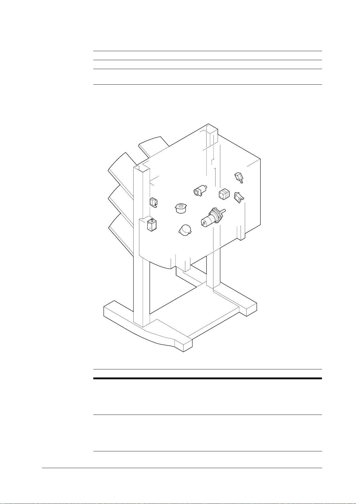
Wiring and function of electrical parts
Symbol Description ID Function
Photo-sensor PS1 Distance sensor
Thermal protec-
tor
Solenoids and motors
TP1 Tr ay elevation motor temperature detec-
tion sensor
SL
TROUBLESHOOTING
SL
SL
M3
M4
M2
M1
SL7
M
Symbol Description ID Function
Solenoids
SL5 Paddle drive solenoid
SL6 Base board shelter solenoid
SL7 Inversion roller drive solenoid
SL8 Face-up flapper drive solenoid
Motors M1 Feed motor
M2 Paper ejecti on mo to r
M3 Matching board movement motor
M4
Stapler movement motor
4-15
Page 92

TROUBLESHOOTING
Wiring and function of electrical parts
Symbol Description ID Function
Printed circuit board
M5
M6
Tray elevation motor
Staple motor
1
4
2
3
Ref. Description Function
Finisher driver circuit
1
board
2
Staple exchange comple-
Control of all types of load and various detection function s
For the use of test stapling
tion switch circuit board
3
Intermediate circuit
board
Interchanges the signals between the various
sensors and loads and the finisher driver circuit board.
DF-30/DF-31
4-16
Page 93

Wiring and function of electrical parts
Ref. Description Function
4
Intermediate circuit
board
5
Intermediate circuit
board
Connectors
Interchanges the signals between the various
sensors and loads and the finisher driver circuit board.
Interchanges the signals between the printer
and the finisher driver circuit board.
TROUBLESHOOTING
1
1
1
1
2
27
2
27
12
123
12
3
134
121
124
3
34
37
33
24
2
127
2
122
11
12
32
11
2
13
31
21
22
1
117
11
1
4-17
Page 94

TROUBLESHOOTING
Wiring and function of electrical parts
212
1
12
27
2
132
2
114
22
131
7
112
111
11
2
11
2
13
13
2
11
1
21
S2
S3
4
17
7
S1
DF-30/DF-31
4-18
Page 95

List of solvents and lubricants
4.8 List of solvents and lubricants
Description Purpose Components Remarks
View clean C-17 Cleaner. Example:
Plastic, rubber, outer
covers
MEK(Methyl Ethyl
Ketone) #160
Lubricant Coated between the
Lubricant Coated on the gear
Cleaner. Example:
Metal, oil soiling,
toner soiling
gear and axis
and axis
Fluoride hydrocarbon,
alcohol, field active
agent, water
Fluoride hydrocarbon,
chlorine hydrocarbon, alcohol
Petroleum based mineral oil
Silicone oil Permalube SHV-2
TROUBLESHOOTING
To not place near
naked flames. Delivered to the site. Substitute: C1, IPA
(isopropyl alcohol)
To not place near
naked flames. Delivered to the site. Substitute: MEK
Selltellus 68 (manufactured by Showa
Shell Sekiyu). Tool
No.: CK-8003
(manufactured by
Nihon Oil). Tool No.:
CK-8005
Note
Ensure that all excess oil has been wiped off after using these solvents.
4-19
Page 96

TROUBLESHOOTING
List of solvents and lubricants
DF-30/DF-31
4-20
 Loading...