

Kyocera 620, 820 Service manual

TASKalfa 620/820
SERVICE
MANUAL
Published in December 2008
842KP110
2KPSM060
First Edition

CAUTION
RISK OF EXPLOSION IF BATTERY IS REPLACED BY AN INCORRECT TYPE. DISPOSE OF
USED BATTERIES ACCORDING TO THE INSTRUCTIONS.
It may be illegal to dispose of this battery into the municipal waste stream. Check with your local
solid waste officials for details in your area for proper disposal.
ATTENTION
IL Y A UN RISQUE D’EXPLOSION SI LA BATTERIE EST REMPLACEE PAR UN MODELE DE
TYPE INCORRECT. METTRE AU REBUT LES BATTERIES UTILISEES SELON LES INSTRUCTIONS DONNEES.
Il peut être illégal de jeter les batteries dans des eaux d’égout municipales. Vérifiez avec les fonctionnaires municipaux de votre région pour les détails concernant des déchets solides et une mise
au rebut appropriée.

Revision history
Revision Date Replaced pages Remarks

This page is intentionally left blank.

Safety precautions
This booklet provides safety warnings and precautions for our service personnel to ensure the safety of
their customers, their machines as well as themselves during maintenance activities. Service personnel
are advised to read this booklet carefully to familiarize themselves with the warnings and precautions
described here before engaging in maintenance activities.
Safety warnings and precautions
Various symbols are used to protect our service personnel and customers from physical danger and
to prevent damage to their property. These symbols are described below:
DANGER: High risk of serious bodily injury or death may result from insufficient attention to or incorrect
compliance with warning messages using this symbol.
WARNING: Serious bodily injury or death may result from insufficient attention to or incorrect compliance
with warning messages using this symbol.
CAUTION: Bodily injury or damage to property may result from insufficient attention to or incorrect
compliance with warning messages using this symbol.
Symbols
The triangle ( ) symbol indicates a warning including danger and caution. The specific point
of attention is shown inside the symbol.
General warning.
Warning of risk of electric shock.
Warning of high temperature.
indicates a prohibited action. The specific prohibition is shown inside the symbol.
General prohibited action.
Disassembly prohibited.
indicates that action is required. The specific action required is shown inside the symbol.
General action required.
Remove the power plug from the wall outlet.
Always ground the copier.

1.Installation Precautions
WARNING
• Do not use a power supply with a voltage other than that specified. Avoid multiple connections to
one outlet: they may cause fire or electric shock. When using an extension cable, always check
that it is adequate for the rated current. .............................................................................................
• Connect the ground wire to a suitable grounding point. Not grounding the copier may cause fire or
electric shock. Connecting the earth wire to an object not approved for the purpose may cause
explosion or electric shock. Never connect the ground cable to any of the following: gas pipes,
lightning rods, ground cables for telephone lines and water pipes or faucets not approved by the
proper authorities. ............................................................................................................................
CAUTION:
• Do not place the copier on an infirm or angled surface: the copier may tip over, causing injury. .......
• Do not install the copier in a humid or dusty place. This may cause fire or electric shock. ................
• Do not install the copier near a radiator, heater, other heat source or near flammable material.
This may cause fire. .........................................................................................................................
• Allow sufficient space around the copier to allow the ventilation grills to keep the machine as cool
as possible. Insufficient ventilation may cause heat buildup and poor copying performance. ...........
• Always handle the machine by the correct locations when moving it. ...............................................
• Always use anti-toppling and locking devices on copiers so equipped. Failure to do this may cause
the copier to move unexpectedly or topple, leading to injury. ...........................................................
• Avoid inhaling toner or developer excessively. Protect the eyes. If toner or developer is accidentally ingested, drink a lot of water to dilute it in the stomach and obtain medical attention immediately. If it gets into the eyes, rinse immediately with copious amounts of water and obtain medical
attention. ......................................................................................................................................
• Advice customers that they must always follow the safety warnings and precautions in the copier’s
instruction handbook. .....................................................................................................................
2.Precautions for Maintenance
WARNING
• Always remove the power plug from the wall outlet before starting machine disassembly. ...............
• Always follow the procedures for maintenance described in the service manual and other related
brochures. .......................................................................................................................................
• Under no circumstances attempt to bypass or disable safety features including safety mechanisms
and protective circuits. .....................................................................................................................
• Always use parts having the correct specifications. ..........................................................................
• Always use the thermostat or thermal fuse specified in the service manual or other related brochure when replacing them. Using a piece of wire, for example, could lead to fire or other serious
accident. ..........................................................................................................................................
• When the service manual or other serious brochure specifies a distance or gap for installation of a
part, always use the correct scale and measure carefully. ................................................................
• Always check that the copier is correctly connected to an outlet with a ground connection. .............
• Check that the power cable covering is free of damage. Check that the power plug is dust-free. If it
is dirty, clean it to remove the risk of fire or electric shock. ..............................................................
• Never attempt to disassemble the optical unit in machines using lasers. Leaking laser light may
damage eyesight. ...........................................................................................................................
• Handle the charger sections with care. They are charged to high potentials and may cause electric
shock if handled improperly. ............................................................................................................
CAUTION
• Wear safe clothing. If wearing loose clothing or accessories such as ties, make sure they are
safely secured so they will not be caught in rotating sections. ..........................................................
• Use utmost caution when working on a powered machine. Keep away from chains and belts. ........
• Handle the fixing section with care to avoid burns as it can be extremely hot. ..................................
• Check that the fixing unit thermistor, heat and press rollers are clean. Dirt on them can cause
abnormally high temperatures. ........................................................................................................
• Do not remove the ozone filter, if any, from the copier except for routine replacement. ....................
• Do not pull on the AC power cord or connector wires on high-voltage components when removing
them; always hold the plug itself. .....................................................................................................
• Do not route the power cable where it may be stood on or trapped. If necessary, protect it with a
cable cover or other appropriate item. .............................................................................................
• Treat the ends of the wire carefully when installing a new charger wire to avoid electric leaks. ........
• Remove toner completely from electronic components. ...................................................................
• Run wire harnesses carefully so that wires will not be trapped or damaged. ....................................
• After maintenance, always check that all the parts, screws, connectors and wires that were
removed, have been refitted correctly. Special attention should be paid to any forgotten connector,
trapped wire and missing screws. ...................................................................................................
• Check that all the caution labels that should be present on the machine according to the instruction
handbook are clean and not peeling. Replace with new ones if necessary. ......................................
• Handle greases and solvents with care by following the instructions below: .....................................
· Use only a small amount of solvent at a time, being careful not to spill. Wipe spills off completely.
· Ventilate the room well while using grease or solvents.
· Allow applied solvents to evaporate completely before refitting the covers or turning the power
switch on.
· Always wash hands afterwards.
• Never dispose of toner or toner bottles in fire. Toner may cause sparks when exposed directly to
fire in a furnace, etc. .......................................................................................................................
• Should smoke be seen coming from the copier, remove the power plug from the wall outlet imme-
diately. ............................................................................................................................................
3.Miscellaneous
WARNING
• Never attempt to heat the drum or expose it to any organic solvents such as alcohol, other than the
specified refiner; it may generate toxic gas. .....................................................................................

This page is intentionally left blank.

CONTENTS
1-1 Specifications
1-1-1 Specifications..........................................................................................................................................1-1-1
1-1-2 Parts names............................................................................................................................................1-1-3
(1) Body ..................................................................................................................................................1-1-3
(2) Operation panel.................................................................................................................................1-1-5
1-1-3 Cross section view..................................................................................................................................1-1-6
1-2 Installation
1-2-1 Installation environment..........................................................................................................................1-2-1
1-2-2 Unpacking and installation......................................................................................................................1-2-3
(1) Installation procedure ........................................................................................................................1-2-3
1-2-3 Setting initial copy modes .....................................................................................................................1-2-16
1-2-4 Installing the key counter (option) .........................................................................................................1-2-17
1-3 Maintenance Mode
1-3-1 Maintenance mode .................................................................................................................................1-3-1
(1) Executing a maintenance item ..........................................................................................................1-3-1
(2) Maintenance mode item list...............................................................................................................1-3-2
(3) Contents of the maintenance mode items.........................................................................................1-3-7
1-3-2 Copier management .............................................................................................................................1-3-97
(1) Using the copier management mode ..............................................................................................1-3-97
(2) Job accounting ................................................................................................................................1-3-98
(3) Default settings for copying.............................................................................................................1-3-99
(4) Common default settings...............................................................................................................1-3-101
(5) Weekly timer..................................................................................................................................1-3-103
(6) Configuring MP tray.......................................................................................................................1-3-103
(7) Registering non-standard sizes for originals.................................................................................1-3-104
(8) Setting document management defaults.......................................................................................1-3-104
(9) Hard disk management .................................................................................................................1-3-104
(10) Printing reports..............................................................................................................................1-3-104
(11) Checking total copy count .............................................................................................................1-3-105
(12) Refreshing the drum......................................................................................................................1-3-105
(13) Selecting the language..................................................................................................................1-3-105
2KN/2KP
1-4 Troubleshooting
1-4-1 Paper misfeed detection .........................................................................................................................1-4-1
(1) Paper misfeed indication ...................................................................................................................1-4-1
(2) Paper misfeed detection conditions ..................................................................................................1-4-2
(3) Paper misfeeds ...............................................................................................................................1-4-10
1-4-2 Self-diagnosis .......................................................................................................................................1-4-26
(1) Self-diagnostic function ...................................................................................................................1-4-26
(2) Self diagnostic codes ......................................................................................................................1-4-28
1-4-3 Image formation problems ....................................................................................................................1-4-50
(1) No image appears (entirely white)...................................................................................................1-4-51
(2) No image appears (entirely black)...................................................................................................1-4-52
(3) Image is too light. ............................................................................................................................1-4-53
(4) Background is visible.......................................................................................................................1-4-53
(5) A white line appears longitudinally. .................................................................................................1-4-53
(6) A black line appears longitudinally. .................................................................................................1-4-54
(7) A black line appears laterally...........................................................................................................1-4-54
(8) One side of the copy image is darker than the other.......................................................................1-4-54
(9) Black dots appear on the image......................................................................................................1-4-55
(10) Image is blurred...............................................................................................................................1-4-55
(11) The leading edge of the image is consistently misaligned with the original. ...................................1-4-55
(12) The leading edge of the image is sporadically misaligned with the original....................................1-4-55
(13) Paper creases. ................................................................................................................................1-4-56
(14) Offset occurs. ..................................................................................................................................1-4-56
(15) Image is partly missing....................................................................................................................1-4-56
(16) Fusing is poor..................................................................................................................................1-4-57
(17) Image is out of focus. ......................................................................................................................1-4-57

2KN/2KP
(18) Image center does not align with the original center.......................................................................1-4-57
(19) Image is not square.........................................................................................................................1-4-57
(20) There is a regular error between the centers of the original and copy image
when the DP is used. ......................................................................................................................1-4-58
(21) There is a regular error between the leading edges of the original and copy image
when the DP is used. ......................................................................................................................1-4-58
(22) A line appears at the leading or trailing edge. .................................................................................1-4-58
(23) A line appears at the leading or trailing edge. .................................................................................1-4-58
1-4-4 Electric problems ..................................................................................................................................1-4-59
1-4-5 Mechanical problems............................................................................................................................1-4-74
1-5 Assembly and Disassembly
1-5-1 Precautions for assembly and disassembly............................................................................................1-5-1
(1) Precautions .......................................................................................................................................1-5-1
(2) Drum..................................................................................................................................................1-5-1
(3) Toner container .................................................................................................................................1-5-1
1-5-2 Paper feed section..................................................................................................................................1-5-3
(1) Detaching and refitting the paper feed pulley, forwarding pulley and separation pulley of
cassette 1 and 2................................................................................................................................1-5-3
(2) Detaching and refitting the paper feed pulley, forwarding pulley and separation pulley of
cassette 3 and 4..............................................................................................................................1-5-10
(3) Pressure adjustment of separation pulley (reference).....................................................................1-5-14
(4) Adjusting the center line for cassette 1 or 2 ....................................................................................1-5-15
(5) Detaching and refitting the MP unit .................................................................................................1-5-17
(6) Detaching and refitting the MP paper feed pulley, MP forwarding pulley and
MP separation pulley.......................................................................................................................1-5-19
(7) Pressure adjustment of MP separation pulley.................................................................................1-5-24
1-5-3 Main charging section...........................................................................................................................1-5-25
(1) Detaching and refitting the main charger unit..................................................................................1-5-25
(2) Detaching and refitting the main charger grid .................................................................................1-5-26
(3) Detaching the main charger wire cleaning pad ...............................................................................1-5-26
(4) Detaching and refitting the main charger wire.................................................................................1-5-27
1-5-4 Optical section ......................................................................................................................................1-5-28
(1) Detaching and refitting the exposure lamp......................................................................................1-5-28
(2) Detaching and refitting the scanner wires .......................................................................................1-5-31
(2-1) Detaching the scanner wires...................................................................................................1-5-31
(2-2) Fitting the scanner wires .........................................................................................................1-5-33
(3) Detaching the laser scanner unit.....................................................................................................1-5-36
(4) Detaching and refitting the ISU (reference).....................................................................................1-5-39
(5) Adjusting the longitudinal squareness (reference)..........................................................................1-5-41
(6) Adjusting scanner image lateral squareness (reference)................................................................1-5-42
(6-1) Adjusting the position of the laser scanner unit.......................................................................1-5-42
(6-2) Adjusting the position of the ISU .............................................................................................1-5-43
1-5-5 Drum section.........................................................................................................................................1-5-44
(1) Detaching and refitting the drum .....................................................................................................1-5-44
(2) Detaching and refitting the drum heater ..........................................................................................1-5-45
(3) Detaching and refitting the drum heater electrode ..........................................................................1-5-47
1-5-6 Developing section................................................................................................................................1-5-48
(1) Detaching and refitting the developing unit .....................................................................................1-5-48
1-5-7 Transfer section ....................................................................................................................................1-5-49
(1) Detaching and refitting the transfer unit ..........................................................................................1-5-49
(2) Detaching and refitting the transfer belt ..........................................................................................1-5-51
(3) Detaching and refitting the transfer roller ........................................................................................1-5-53
1-5-8 Cleaning section ...................................................................................................................................1-5-54
(1) Detaching and refitting the cleaning unit.........................................................................................1-5-54
(2) Detaching and refitting the cleaning blade......................................................................................1-5-55
1-5-9 Charge erasing section.........................................................................................................................1-5-56
(1) Detaching and refitting the PTC unit ...............................................................................................1-5-56
(2) Detaching and refitting the PTC cleaning pad.................................................................................1-5-56
(3) Detaching and refitting the PTC wire...............................................................................................1-5-57
1-5-10 Fuser section ........................................................................................................................................1-5-58
(1) Detaching and refitting the fuser unit...............................................................................................1-5-58
(2) Detaching and refitting the lower cleaning roller .............................................................................1-5-59

2KN/2KP
(3) Detaching and refitting the press roller............................................................................................1-5-60
(4) Detaching and refitting the cleaning felt..........................................................................................1-5-61
(5) Detaching and refitting the fuser thermostat 1 and 2 ......................................................................1-5-63
(6) Detaching and refitting the fuser thermistor M and S ......................................................................1-5-65
(7) Detaching and refitting the fuser heater M, S and L........................................................................1-5-66
(8) Detaching and refitting the heat roller .............................................................................................1-5-70
(9) Detaching and refitting the heat roller separation claws..................................................................1-5-71
(10) Detaching and refitting the fuser eject upper roller..........................................................................1-5-72
1-5-11 Document processor (DP) section........................................................................................................1-5-73
(1) Detaching and refitting DP ..............................................................................................................1-5-73
(2) Detaching and refitting the DP original feed belt, DP forwarding pulley and
DP separation roller.........................................................................................................................1-5-75
(3) Detaching and refitting CIS .............................................................................................................1-5-79
(4) Adjusting the tension of original feed belt........................................................................................1-5-82
1-5-12 Others ...................................................................................................................................................1-5-83
(1) Detaching and refitting the waste toner box....................................................................................1-5-83
(2) Detaching and refitting the developing rear fan filter.......................................................................1-5-84
(3) Detaching and refitting the developing front fan filters ....................................................................1-5-84
(4) Detaching and refitting the image formation fan filter......................................................................1-5-85
(5) Detaching and refitting the front cover filters...................................................................................1-5-86
(6) Detaching and refitting the ozone filters..........................................................................................1-5-87
1-6 Requirements on PWB Replacement
1-6-1 Upgrading the firmware...........................................................................................................................1-6-1
1-6-2 Adjustment-free variable resistors (VR) ..................................................................................................1-6-2
1-6-3 Remarks on main PWB replacement......................................................................................................1-6-2
1-6-4 Remarks on engine PWB replacement...................................................................................................1-6-3
1-6-5 Remarks on scanner PWB replacement.................................................................................................1-6-3
1-6-6 Upgrading the printer board firmware .....................................................................................................1-6-4
1-6-7 Remarks on hard disk unit (HDD) replacement ......................................................................................1-6-4
2-1 Mechanical construction
2-1-1 Paper feed section..................................................................................................................................2-1-1
(1) Paper feed section 1 (cassette 1 and 2)............................................................................................2-1-1
(2) Paper feed section 2 (cassette 3 and 4)............................................................................................2-1-3
(3) Paper feed section 3 .........................................................................................................................2-1-5
(4) MP tray and MP tray paper feed section...........................................................................................2-1-7
2-1-2 Main charger section...............................................................................................................................2-1-9
2-1-3 Optical section ......................................................................................................................................2-1-11
(1) Original scanning.............................................................................................................................2-1-12
(2) Image printing..................................................................................................................................2-1-13
2-1-4 Developing section................................................................................................................................2-1-15
(1) Single component developing system.............................................................................................2-1-17
2-1-5 Transfer section ....................................................................................................................................2-1-18
2-1-6 Cleaning section ...................................................................................................................................2-1-19
2-1-7 Fuser section ........................................................................................................................................2-1-20
2-1-8 PTC section ..........................................................................................................................................2-1-22
2-1-9 Eject and feedshift section ....................................................................................................................2-1-24
2-1-10 Duplex section ......................................................................................................................................2-1-26
(1) Circulation system (4 sheets circulation).........................................................................................2-1-28
2-1-11 Document processor (DP) section........................................................................................................2-1-29
2-2 Electrical Parts Layout
2-2-1 Electrical parts layout..............................................................................................................................2-2-1
(1) PWBs ................................................................................................................................................2-2-1
(2) Switches and sensors .......................................................................................................................2-2-3
(3) Motors ...............................................................................................................................................2-2-5
(4) Others................................................................................................................................................2-2-7
(5) PWBs (DP)........................................................................................................................................2-2-8
(6) Switches and sensors (DP)...............................................................................................................2-2-9
(7) Others (DP) .....................................................................................................................................2-2-10

2KN/2KP
2-3 [Operation of the PWBs
2-3-1 AC power source PWB ...........................................................................................................................2-3-1
2-3-2 DC power source PWB...........................................................................................................................2-3-5
2-3-3 Main PWB.............................................................................................................................................2-3-10
2-3-4 Engine PWB..........................................................................................................................................2-3-19
2-3-5 Scanner PWB .......................................................................................................................................2-3-28
2-3-6 CCD PWB .............................................................................................................................................2-3-32
2-3-7 Deck PWB.............................................................................................................................................2-3-35
2-3-8 Cassette PWB.......................................................................................................................................2-3-41
2-3-9 Duplex PWB..........................................................................................................................................2-3-44
2-3-10 Operation PWB.....................................................................................................................................2-3-49
2-3-11 HDD relay PWB ....................................................................................................................................2-3-53
2-3-12 DP main PWB.......................................................................................................................................2-3-56
2-4 Appendixes
Maintenance parts list.............................................................................................................................2-4-1
Periodic maintenance procedures ..........................................................................................................2-4-3
Maintenance kits.....................................................................................................................................2-4-9
Parts kits ...............................................................................................................................................2-4-10
Wiring diagram No.1 .............................................................................................................................2-4-13
Wiring diagram No.2 .............................................................................................................................2-4-14
Wiring diagram No.3 .............................................................................................................................2-4-15
Wiring diagram No.4 .............................................................................................................................2-4-16
Wiring diagram No.5 .............................................................................................................................2-4-17
Wiring diagram No.6 .............................................................................................................................2-4-18
Wiring diagram No.7 .............................................................................................................................2-4-19
Wiring diagram No.8 .............................................................................................................................2-4-20
Wiring diagram No.9 .............................................................................................................................2-4-21
Wiring diagram No.10 ...........................................................................................................................2-4-22
INSTALLATION GUIDE
SIDE FEEDER
LARGE SIZE SIDE FEEDER
DOCUMENT FINISHER
CENTERFOLD UNIT
MULTI JOB TRAY
PUNCH UNIT
STOPPER GUIDE
PRINTING SYSTEM
SCAN SYSTEM

2KN/2KP
1-1 Specifications
1-1-1 Specifications
Type................................................Console
Copying system ..............................Indirect electrostatic system
Supported original types ................. Sheets, books and three-dimensional objects
Maximum size: A3/11" x 17"
Original feed system .......................Fixed
Paper weight...................................Cassette: 60 - 160 g/m
MP tray : 45 - 200 g/m
Paper type ......................................Cassette: Plain, Recycled, Preprinted, Bond, Color (Colour), Letterhead, Thick paper,
High Quality and Custom 1-8
MP tray :Plain, Transparency, Rough, Vellum, Labels, Recycled, Preprinted, Bond,
Cardstock, Color (Colour), Prepunched, Letterhead, Thick paper, Envelope,
High Quality and Custom 1-8
Paper size.......................................Cassettes 1 and 2:
11 x 8
Cassettes 3 and 4:
11 x 17", 8
1/2 x 13 1/2", A3, B4, A4, A4R, B5, B5R, A5R, Folio, 8K and 16K.
8
MP tray : 5 1/2 x 8 1/2" to 11 x 17", A5R to A3, B6R, A6R, Folio, 8K, 16K, YOUKEI 2
and YOUKEI 4
Duplexing
:5 1/2 x 8 1/2" to 11 x 17", A5R to A3
Zoom level ......................................Any level from 25 to 400 %, 1% increments
With the document processor: 25 to 200 %
Includes preset zoom levels
Copying speed................................At 100% magnification in memory copy mode:
82 cpm
A3/11 x 17": 41 sheets/min.
1/2 x 14": 50 sheets/min.
B4/8
A4/11 x 8
1/2": 82 sheets/min.
A4R/8 1/2 x 11": 54 sheets/min.
B5: 80 sheets/min.
B5R: 58 sheets/min.
When the document processor is used (at 100% magnification):
A4/11 x 8
1/2": 82 sheets/min.
62 cpm
A3/11 x 17": 31 sheets/min.
1/2 x 14": 37 sheets/min.
B4/8
A4/11 x 8
1/2": 62 sheets/min.
A4R/8 1/2 x 11": 43 sheets/min.
B5: 60 sheets/min.
B5R: 47 sheets/min.
When the document processor is used (at 100% magnification):
A4/11 x 8
1/2": 62 sheets/min.
First copy time ................................82 cpm: 2.9 s or less
62 cpm: 3.6 s or less
(A4/11 x 8
1/2", 100% magnification)
Warm-up time .................................30 s
Recovery from low power mode: 10 s
Recovery from sleep mode: 30 s
(At room temperature 22
Paper capacity ................................Cassettes 1 and 2: 1500 sheets (80 g/m
Cassettes 3 and 4: 500 sheets (80 g/m2)/525 sheets (75 g/m2) x 2
MP tray: 100 sheets (80 g/m2)
Output tray capacity........................250 sheets (80 g/m2)
Continuous copying ........................1 - 9999 sheets
Light source ....................................Inert gas lamp
Scanning system ............................Flat bed scanning by CCD image sensor
Photoconductor...............................a-Si (drum diameter 84 mm)
Image write system.........................Semiconductor laser
Charging system.............................Double positive corona charging
2
2
1/2" and A4
1/2 x 14", 11 x 8 1/2", 8 1/2 x 11", 5 1/2 x 8 1/2", 8 1/2 x 13",
°C/71.6 °F, 60%RH)
2
) x 2
1-1-1

2KN/2KP
Developing system .........................Dry, reverse developing (single component system)
Developer: 1-component, magnetism toner
Toner replenishing: Automatic from a toner container
Transfer system ..............................Transfer belt and transfer roller
Separation system..........................Transfer belt and separation claws
Cleaning system .............................Blade and fur brush
Charge erasing system...................Exposure by cleaning lamp
Fusing system.................................Heat roller
Heat source: Halogen heaters
Abnormally high temperature protection devices: thermostats
Main memory ..................................128 MB
Hard disk.........................................40 GB
Resolution.......................................Scanning: 600 x 600 dpi
Copying : Equivalent to 1800 x 600 dpi
Operating environment ................... Temperature: 10 to 32.5
°C/50 to 90.5°F
Humidity: 15 to 80% RH
Altitude: 2000 m/8,202 ft maximum
Brightness: 1500 lux maximum
Dimensions .....................................680 (W) x 811 (D) x 1190 (H) mm
3/4" (W) x 31 15/16" (D) x46 7/8" (H)
26
Weight.............................................Approx. 188 kg/Approx. 413.6 lbs
Space required................................1480 mm (W) x 811 (D) mm
1/4" (W) x 31 15/16" (D)
58
Power source..................................120 V AC, 60 Hz, 16.0 A
220 - 240 V AC, 50/60 Hz, 9.5 A
Power consumption ........................ 1920 W
Options ...........................................Side feeder, Large size side feeder, Document finisher, Centerfold unit, Multi job tray,
Punch unit, Key counter, Printer kit, Scanner kit, Security kit and Output tray
Document processor
Original feed system .......................Automatic feed
Scanning system ............................Contact Image Sensor (CIS)
Supported original types ................. Sheets
Original weights ..............................45 - 160 g/m
2
Original sizes ..................................A3 - A5R, folio/11" x 17" - 5 1/2" x 8 1/2"
Loading capacity.............................Standard paper (80 g/m2), colored paper or recycled paper: 200 sheets
(30 sheets in mixed size originals mode)
Coated paper: 1 sheet
High quality paper (50 g/m2): 200 sheets
High quality paper (110 g/m2): 145 sheets
Power source..................................Supplied via machine
NOTE: These specifications are subject to change without notice.
1-1-2
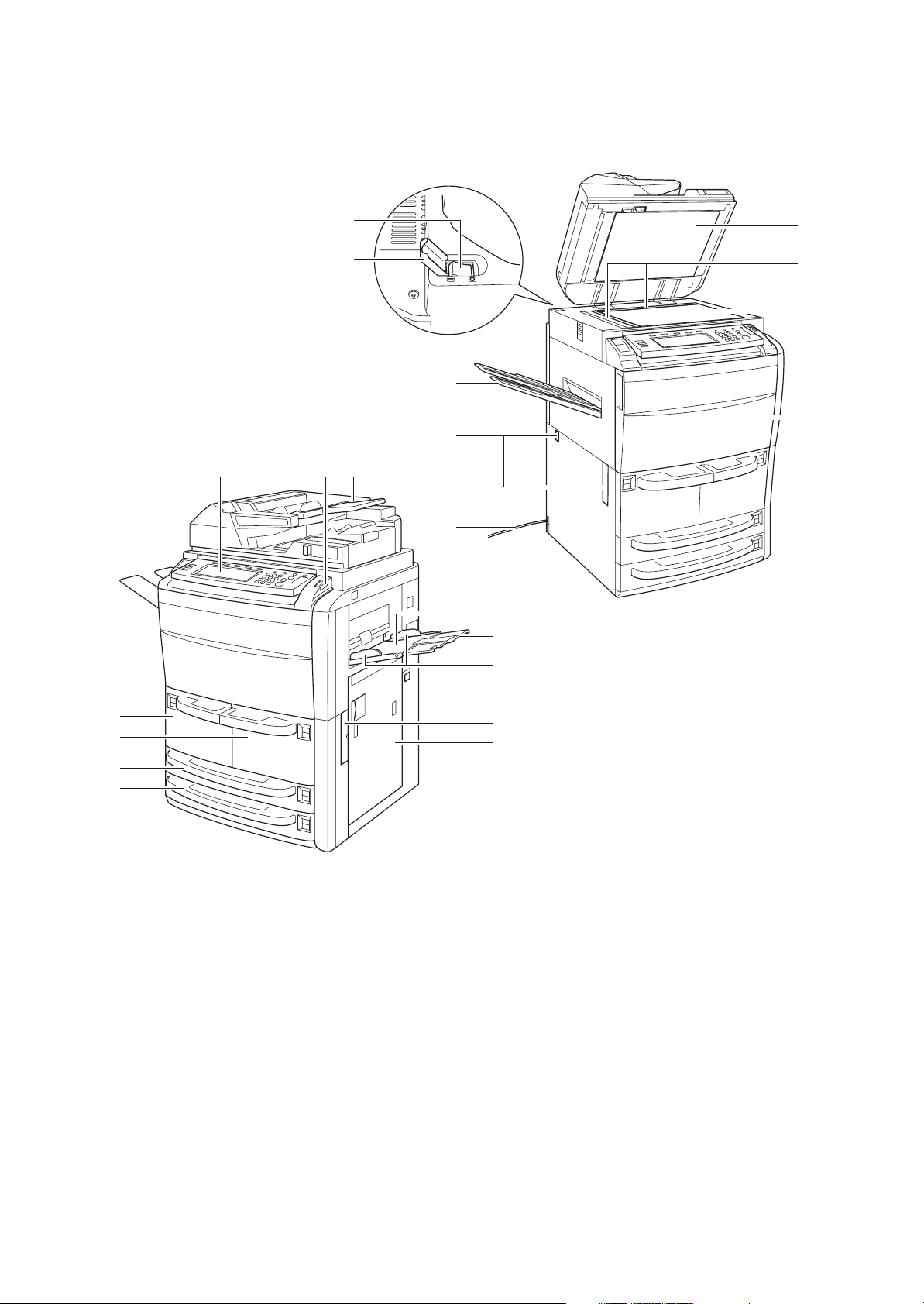
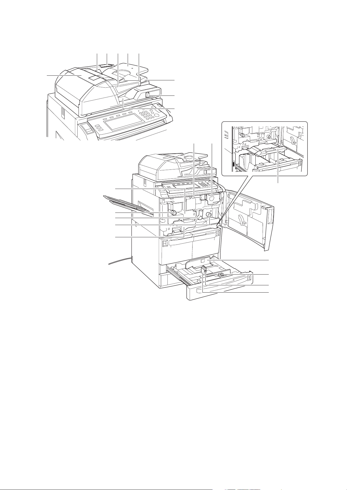
1-1-2 Parts names
(1) Body
2KN/2KP
13
14
12
3
15
16
17
19
18
20
21
8
10
9
5
4
6
7
Figure 1-1-1
1. Operation panel
2. Operation panel lock lever
3. Document processor (DP)
4. Cassette 1
5. Cassette 2
6. Cassette 3
7. Cassette 4
8. MP tray (multi-purpose tray)
9. Paper width guides
10. MP tray extension
11. Right cover
12
11
12. Handles
13. Main power switch
14. Main power switch cover
15. Document processor bottom cover
16. Original size indicator plates
17. Platen
18. Front cover
19. Output tray (option)
20. Handles
21. Power cord
1-1-3
2KN/2KP
26
25
2223
24 23
32
33
34
35
27
28
29
3031
37
36
22. Original table
23. Original width guides
24. Cleaning cloth compartment
25. Original loaded Indicator
26. Document processor top cover
27. Ejection guide
28. Document processor angle adjustment lever
29. Original eject table
30. Toner container
31. Toner container release lever
38
39
41
40
Figure 1-1-2
32. Paper conveyor
33. Knob A1
34. Lever A2
35. Knob A3
36. Duplex unit
37. Deck conveying unit
38. Paper width guides
39. Paper width adjusting tab
40. Paper length guide
41. Paper length adjusting tab
1-1-4
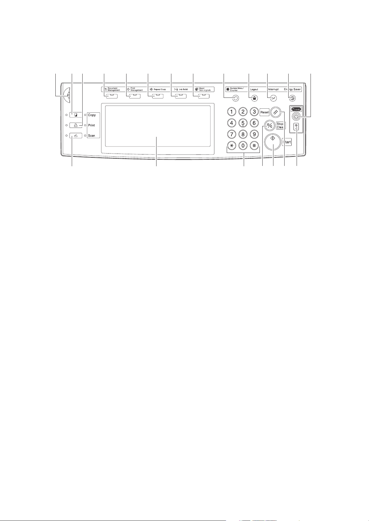
(2) Operation panel
21356789 1011121319
414 1816201715
2KN/2KP
Figure 1-1-3
1. Brightness adjustment dial
2. Copy key/indicator
3. Printer key/indicator
4. Scann key/indicator
5. Document management key/indicator
6. Print management key/indicator
7. Repeat copy key/indicator
8. Job build key/indicator
9. Mixed size originals key/indicator
10. System menu/counter key
11. Logout key
12. Interrupt key/indicator
13. Energy saver key/indicator
14. Touch panel
15. Numeric keys
16. Reset key
17. Stop/clear key
18. Start key/indicator
19. Power key/indicator
20. Main power indicator
1-1-5
2KN/2KP
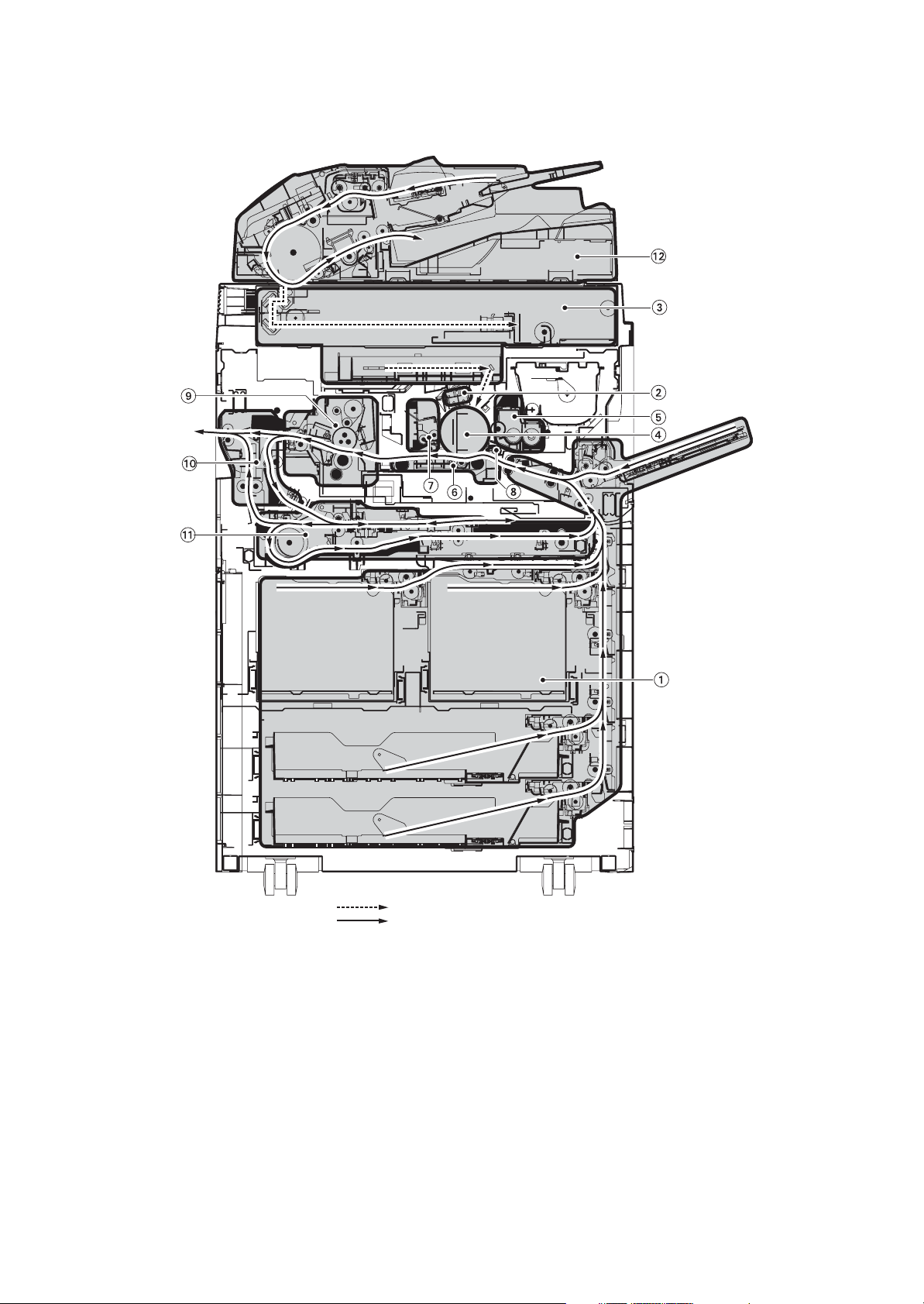
1-1-3 Cross section view
1-1-6
1. Paper feed section
2. Main charging section
3. Optical section
4. Drum section
5. Developing section
6. Transfer section
Light path
Paper and original path
Figure 1-1-4
7. Cleaning section
8. PTC section
9. Fuser section
10. Feedshift and eject section
11. Duplex section
12. Document processor

1-2Installation
1-2-1 Installation environment
1. Temperature: 10 - 32.5 °C/50 - 90.5 °F
2. Humidity: 15 - 80%RH
3. Power supply: 120 V AC, 16.0 A
220 - 240 V AC, 9.5 A
4. Power source frequency: 50 Hz
5. Installation location
Avoid direct sunlight or bright lighting. Ensure that the photoconductor will not be exposed to direct sunlight or
other strong light when removing paper jams.
Avoid locations subject to high temperature and high humidity or low temperature and low humidity; an abrupt
change in the environmental temperature; and cool or hot, direct air.
Avoid places subject to dust and vibrations.
Choose a surface capable of supporting the weight of the machine.
Place the machine on a level surface (maximum allowance inclination: 1
Avoid air-borne substances that may adversely affect the machine or degrade the photoconductor, such as mercury, acidic of alkaline vapors, inorganic gasses, NOx, SOx gases and chlorine-based organic solvents.
Select a well-ventilated location.
6. Allow sufficient access for proper operation and maintenance of the machine.
Machine front: 1000 mm/39
Machine right: 700 mm/27 9/16" Machine left: 600 mm/23 5/8"
±2%/60 Hz ±2%
°).
3/8" Machine rear: 100 mm/3 15/16"
2KN/2KP
1-2-1
2KN/2KP
d
a
c
b
60
30
f
e
1-2-2
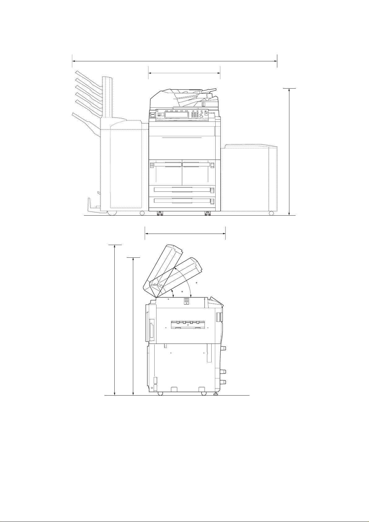
a: 680 mm/26 3/4"
b: 811 mm/31
c: 1190 mm/46
d: 2148 mm/84
e: 1465 mm/57
f: 1530 mm/60
15/16"
7/8"
9/16"
11/ 16"
3/16"
Figure 1-2-1 Installation dimensions
1-2-2 Unpacking and installation
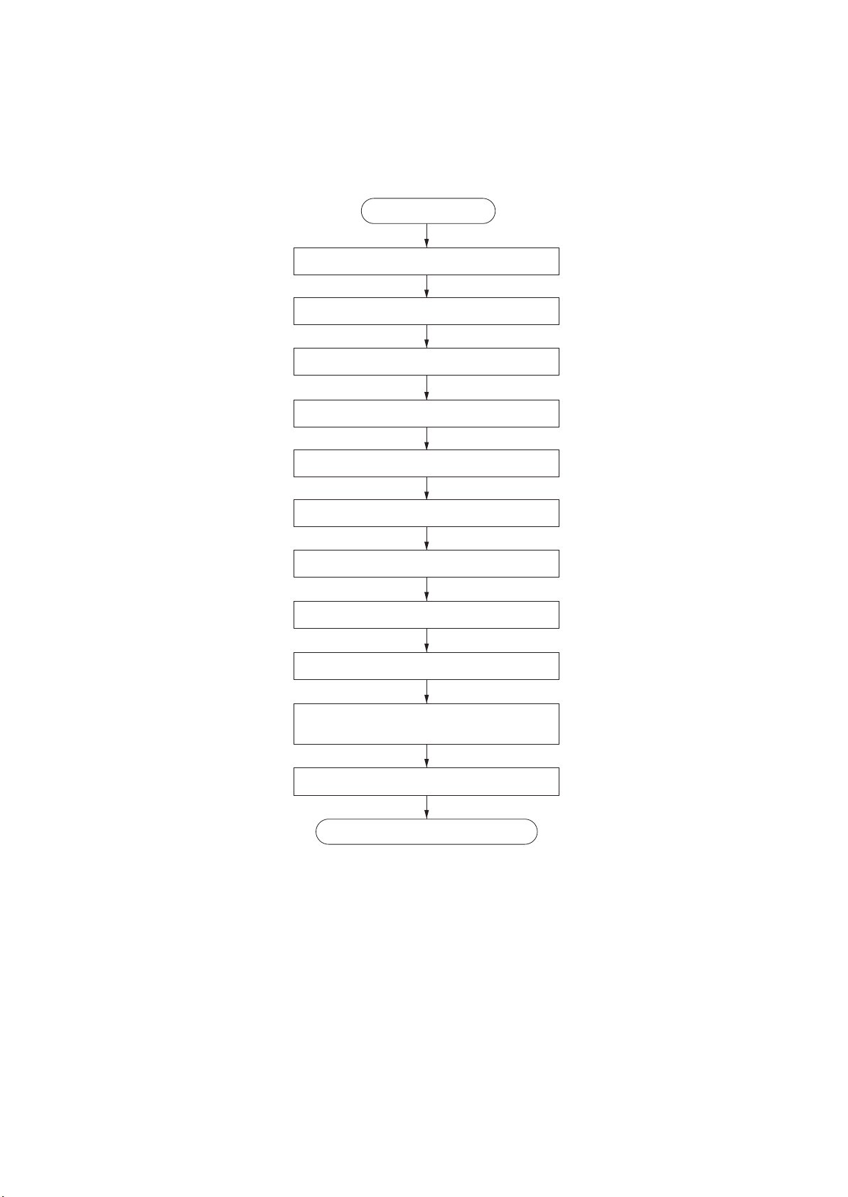
(1) Installation procedure
2KN/2KP
Start
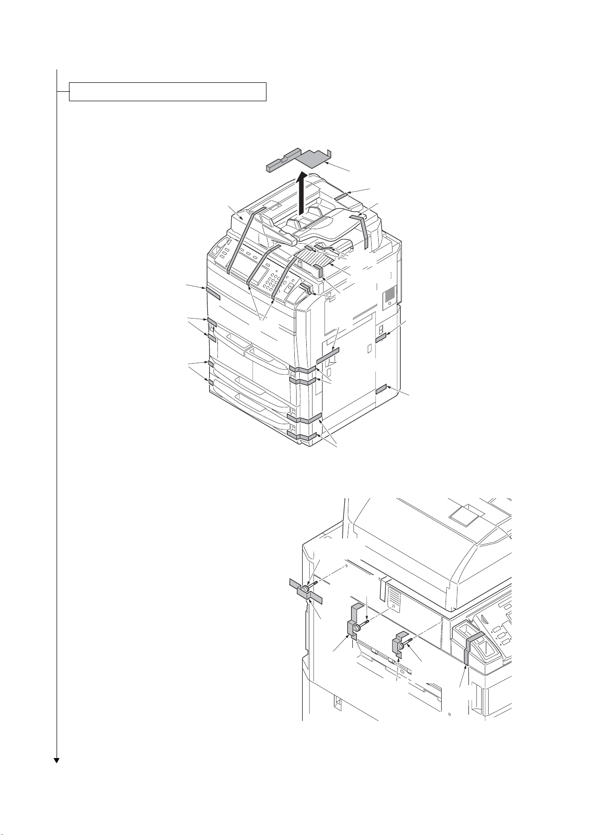
Unpacking.
Taking out the machine.
Remove the tapes, pins, spacers and sheet.
Remove the screws.
Remove the tapes of transfer section.
Installing the toner container.
Connecting the power cord.
Initial setting for the developer.
Make test copies.
Attaching the language label
(230 V specifications only).
Installing the guide case.
Completion of the machine installation.
1-2-3
2KN/2KP
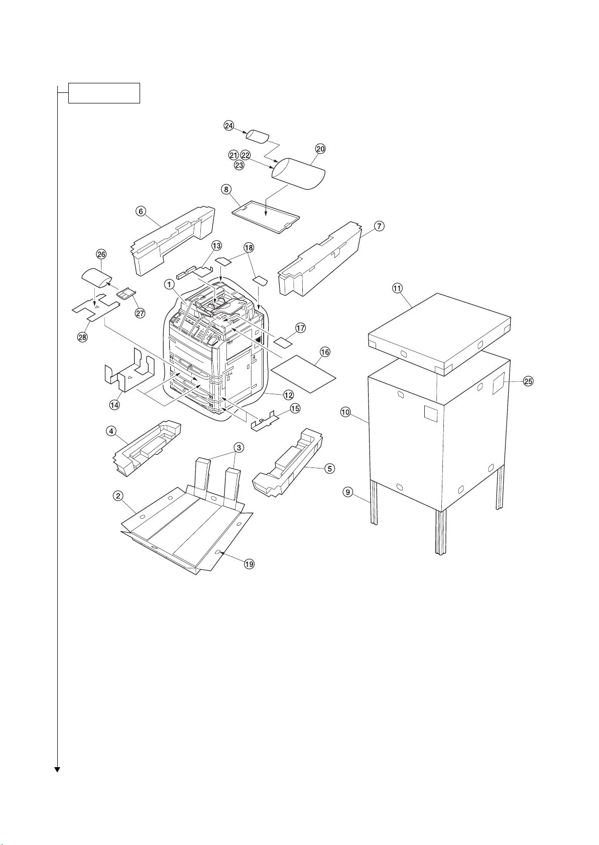
Unpacking.
1. Machine
2. Skid
3. Slopes
4. Lower left spacer
5. Lower right spacer
6. Upper left spacer
7. Upper right spacer
8. Upper spacer
9. Supports
10. Outer case
11. Upper case
12. Machine cover
13. DP spacer
14. Deck spacers
Place the machine on a level surface.
1-2-4
Figure 1-2-2 Unpacking
15. Cassette spacers
16. Sheet
17. DP sheet
18. Rear sheets
19. Hinge joints
20. Plastic bag
21. Operation guide
22. Casette size plates
23. Labels
24. Cursor pins
25. Bar code labels
26. Plastic bag
27. Guide case
28. Spacer
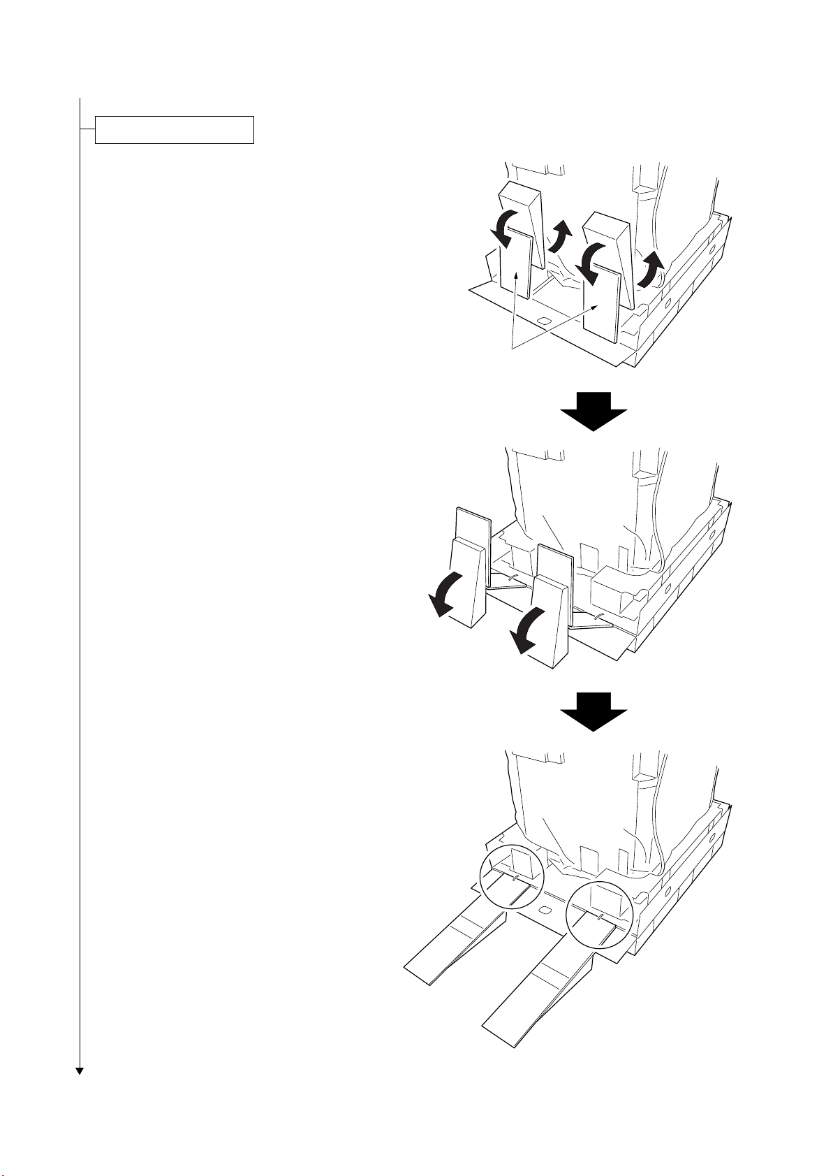
Taking out the machine.
When taking out the machine, a space for
machine rear requires approximately 2 m.
1. Remove the hinge joints, and then remove
the upper case, the upper spacer, the upper
left spacer, the upper right spacer, the outer
case and the supports.
2. Cut four tapes of the skid each corner.
3. Cut each tape which locks the slope and the
spacer.
4. Rotate slopes as shown in the figure and
make them for machine sliding.
* Finally, check that there is no level differ-
ence in slopes (circle section of figure 1-2-
3).
2KN/2KP
Slopes
Figure 1-2-3
1-2-5
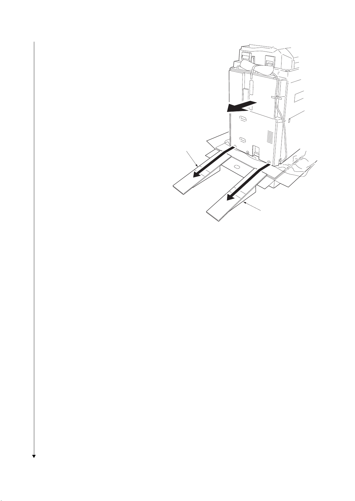
2KN/2KP
5. Remove the machine cover and pull out the
handles on machine left and right.
6. Lift the machine each left and right one side,
and then remove the lower left and right
spacers.
7. Move the machine alongside slopes to slide
to the floor.
Slope
Figure 1-2-4
Slope
1-2-6
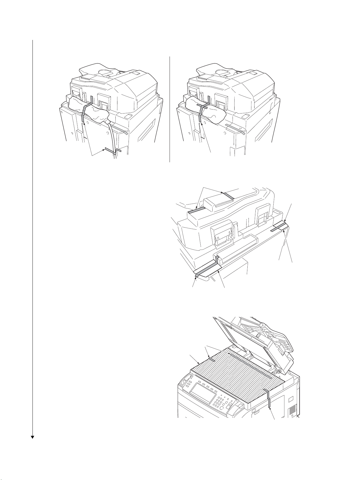
Remove the tapes, pins, spacers and sheet.
1. Remove nineteen tapes, DP spacer and DP
sheet.
Ta pe
Ta pe
2KN/2KP
DP spacer
Ta pe
Ta pe
Ta pe s
DP sheet
Ta pe s
Ta pe s
Ta pe s
2. Remove four tapes and three pins.
Ta pe s
Figure 1-2-5
Ta pe
Ta pe s
Ta pe s
Pin for light
source unit 1
Pin for light
source unit 2
Ta pe
Ta pe
Ta pe
Ta pe
Pin for light
source unit 1
Ta pe
Figure 1-2-6
Ta pe
1-2-7
2KN/2KP
3. 120 V specifications: Remove the two tapes of power cord.
230 V specifications: Remove the tape of power cord.
120 V specifications 230 V specifications
Ta pe s
4. Remove four tapes and two rear sheets.
Figure 1-2-7
Ta pe
Ta pe
Ta pe s
Ta pe
Rear sheet
Rear sheet
Figure 1-2-8
5. Open the DP and then remove three tapes
and sheet.
1-2-8
Ta pe s
Sheet
Ta pe
Figure 1-2-9
2KN/2KP
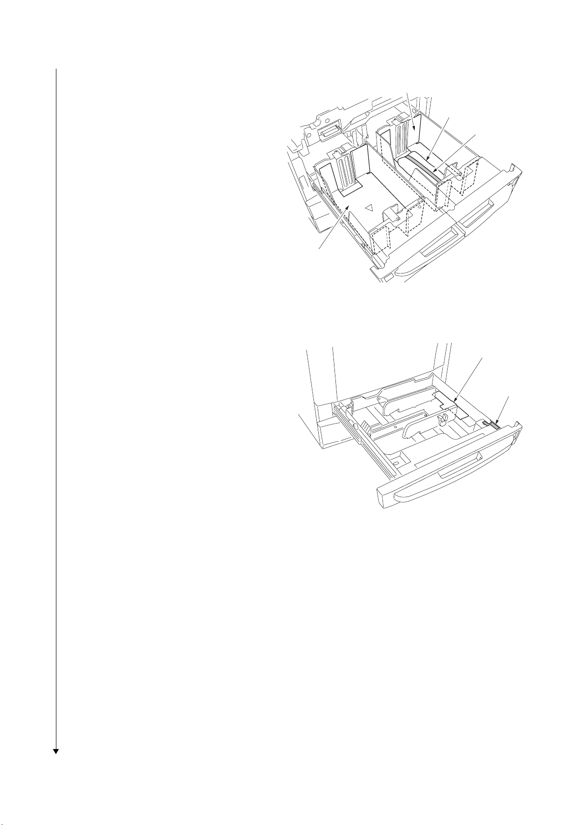
6. Pull out cassette 1 and 2, then remove two
deck spacers.
7. Remove the tape from the deck spacer of
cassette 1 and then remove the guide case.
8. Pull out cassette 3 and 4, then remove two
cassette spacers and tapes.
Deck spacer
Guide case
Ta pe
Deck spacer
Figure 1-2-10
Cassette spacer
Figure 1-2-11
Ta pe
1-2-9
2KN/2KP
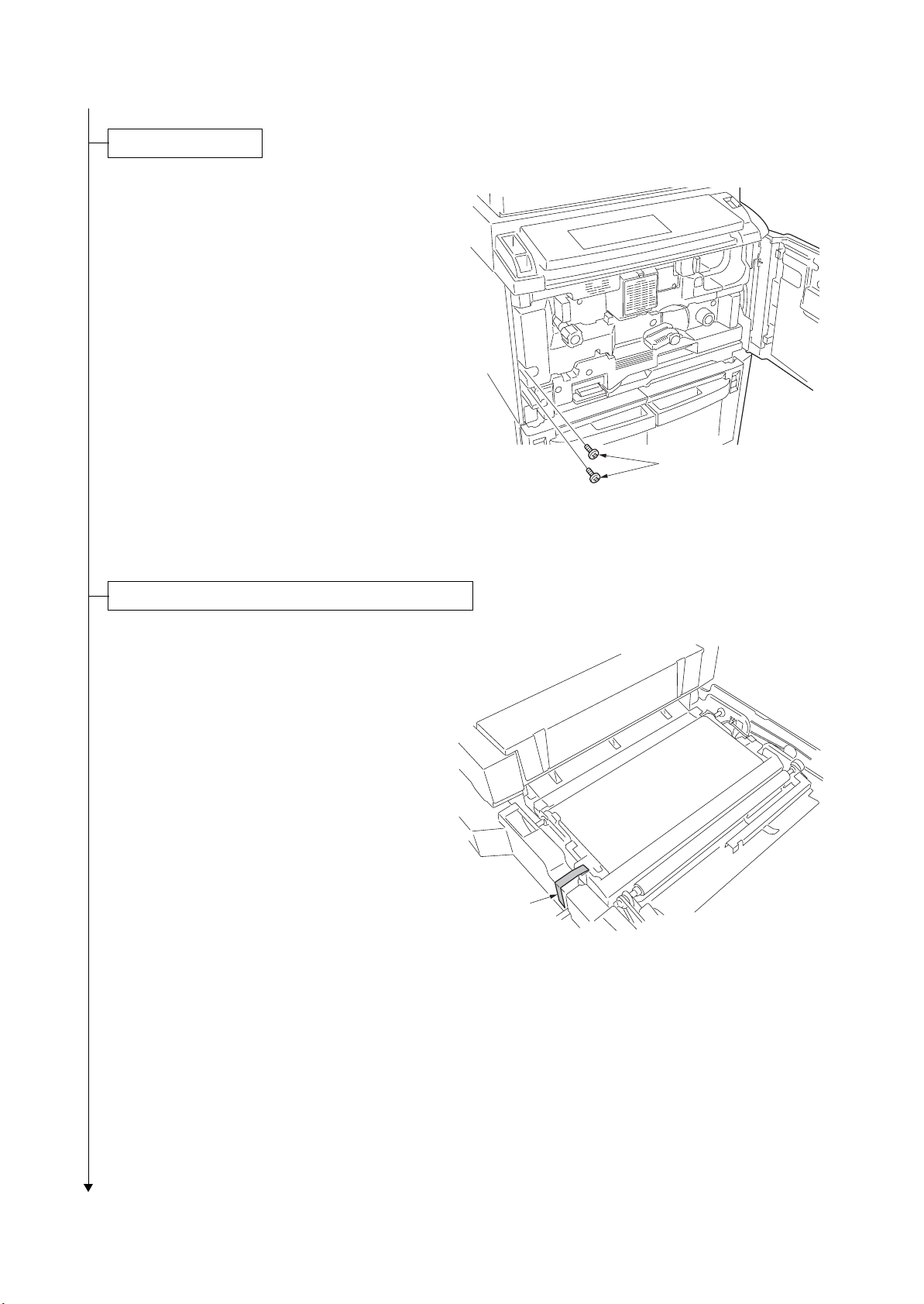
Remove the screws.
1. Open the front cover and remove two
screws.
Screws
Figure 1-2-12
Remove the tapes of transfer section and duplex unit.
1. Pull out the paper conveying unit.
2. Remove the tape from the transfer section.
3. Refit the paper conveying unit.
Ta pe
Figure 1-2-13
1-2-10
 Loading...