

Page 1
8. CYLINDER/PISTON
8-0
8
Do not bend
Page 2
8. CYLINDER/PISTON
8-1
SERVICE INFORMATION
GENERAL INSTRUCTIONS
• The cylinder and piston can be serviced with the engine installed in the frame.
• After disassembly, clean the removed parts and dry them with compressed air before inspection.
SPECIFICATIONS
Item
Standard (mm)
Service Limit (mm)
I.D.
52.400_ 52.410
52.50
Warpageæ0.05
Cylindricity
æ
0.05
True roundness
æ
0.05
Ring-to-groove
Top
0.015_ 0.055
0.09
clearance
Second
0.015_ 0.055
0.09
Top
0.10_ 0.25
0.5
Piston,
Ring end gap
Second
0.10_ 0.25
0.5
piston ring
Oil side rail
0.2_ 0.7
æ
Piston O.D.
52.370_ 52.390
52.3
Piston O.D. measuring position
9mm from bottom of skirt
æ
.
Piston-to-cylinder clearance
0.010_ 0.040
0.1
Piston pin hole I.D.
15.002_ 15.008
15.04
Piston pin O.D
14.994_ 15.000
14.96
Piston-to-piston pin clearance
0.002_ 0.014
0.02
Connecting rod small end I.D. bore
15.016_ 15.034
15.06
TROUBLESHOOTING
• When hard starting or poor performance at low speed occurs, check the crankcase breather for
white smoke. If white smoke is found, it means that the piston rings are worn, stuck or broken.
Compression too low or uneven
compression Excessive smoke from exhaust muffler
• Worn, stuck or broken piston rings • Worn or damaged piston rings
• Worn or damaged cylinder and piston • Worn or damaged cylinder and piston
Compression too high Abnormal noisy piston
• Excessive carbon build-up in combustion • Worn cylinder, piston and piston rings
chamber or on piston head
• Worn piston pin hole and piston pin
Cylinder
SERVICE INFORMATION
......................
8-1 PISTON REMOVAL
.................................
8-3
TROUBLESHOOTING
.............................
8-1 PISTON INSTALLATION
.......................
8-6
CYLINDER REMOVAL
............................
8-2 CYLINDER INSTALLATION
.................
8-6
Page 3
8. CYLINDER/PISTON
8-2
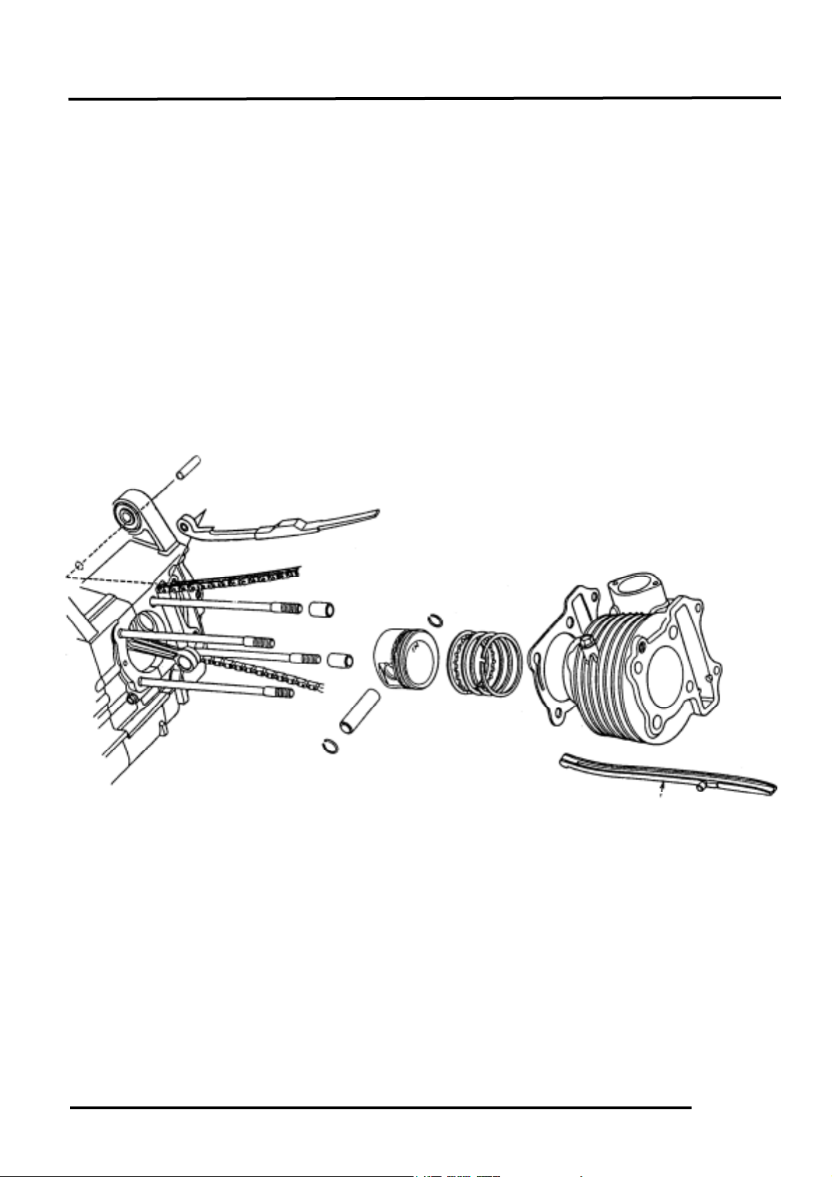
CYLINDER REMOVAL
Remove the cylinder head. (!7-6)
Remove the cam chain guide.
Remove the cylinder base bolts.
Remove the cylinder.
Remove the cylinder gasket and dowel pins.
Clean any gasket material from the cylinder
surface.
PISTON REMOVAL
Remove the piston pin clip.
Press the piston pin out of the piston and
remove the piston.
Dowel Pins
Gasket
Cylinder
Piston
Piston Rings
Place a clean shop towel in the crankcase
to keep the piston pin clip from falling
into the crankcase.
*
Page 4

8. CYLINDER/PISTON
8-3
Inspect the piston, piston pin and piston
rings.
Remove the piston rings.
Clean carbon deposits from the piston ring
grooves.
Install the piston rings onto the piston and
measure the piston ring-to-groove clearance.
Service Limits: Top: 0.09mm replace if over
2nd: 0.09mm replace if over
Remove the piston rings and insert each
piston ring into the cylinder bottom.
Measure the piston ring end gap.
Service Limit: 0.5mm replace if over
Measure the piston pin hole I.D.
Service Limit: 15.04mm replace if below
Take care not to damage or break the
piston rings during removal.
*
Use the piston head to push each piston
ring into the cylinder.
*
Page 5

8. CYLINDER/PISTON
8-4
Measure the piston pin O.D.
Service Limit: 14.96mm replace if below
Measure the piston O.D.
Service Limit: 52.3mm replace if below
Measure the piston-to-piston pin clearance.
Service Limit: 0.02mm replace if over
CYLINDER INSPECTION
Inspect the cylinder bore for wear or damage.
Measure the cylinder I.D. at three levels of
top, middle and bottom at 90° to the piston
pin (in both X and Y directions).
Service Limit: 52.50mm repair or replace if
below
Measure the cylinder-to-piston clearance.
Service Limit: 0.1mm repair or replace if
below
The true roundness is the difference between
the values measured in X and Y directions.
The cylindricity (difference between the
values measured at the three levels) is subject
to the maximum value calculated.
Service Limits:
True Roundness: 0.05mm repair or replace
if over
Cylindricity: 0.05mm repair or replace if over
Take measurement at 9mm from the
bottom and 90° to the piston pin hole.
*
Middle
Bottom
Top
Page 6

8. CYLINDER/PISTON
8-5
Inspect the top of the cylinder for warpage.
Service Limit: 0.05mm repair or replace if below
Measure the connecting rod small end I.D.
Service Limit: 15.06mm replace if below
PISTON RING INSTALLATION
Install the piston rings onto the piston.
Apply engine oil to each piston ring.
Second
Side Rail
Top
• Be careful not to damage or break
the piston and piston rings.
• All rings should be installed with
the markings facing up.
• After installing the rings, they
should rotate freely without sticking.
*
Second
Top
Side Rail
Oil Ring
Page 7

8. CYLINDER/PISTON
8-6
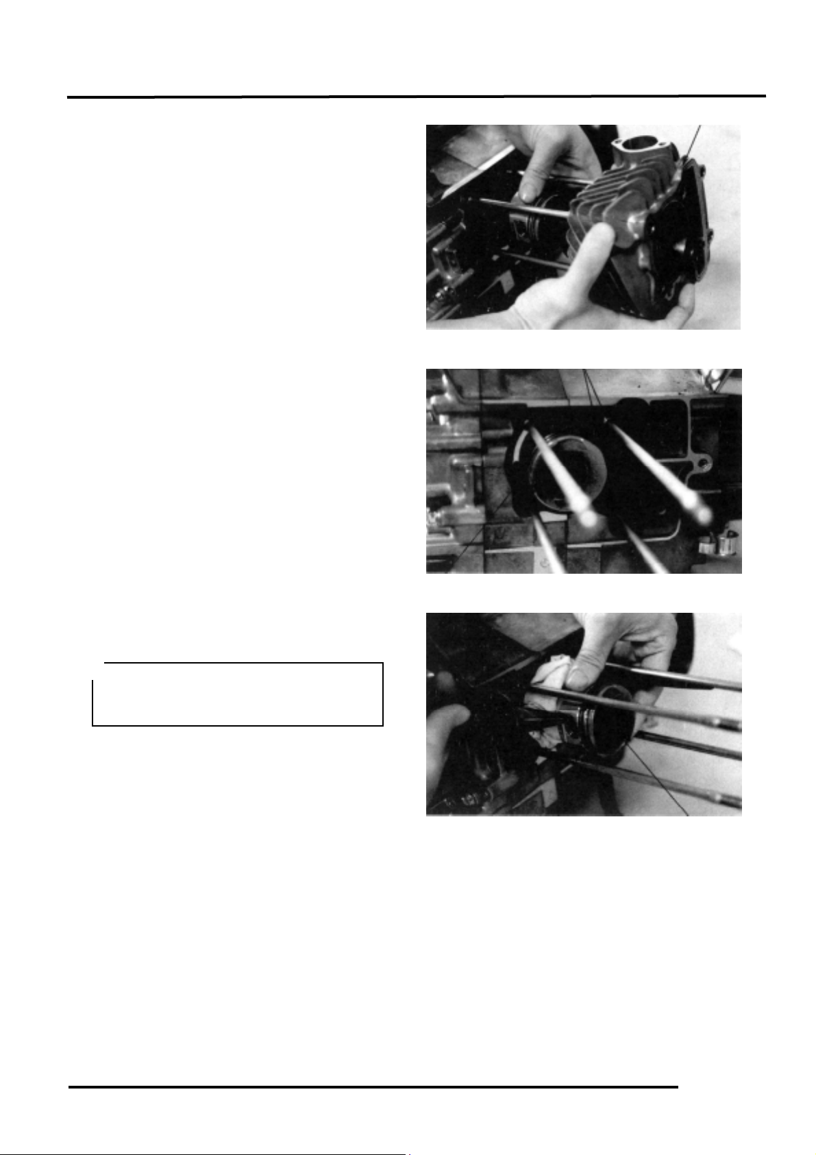
PISTON INSTALLATION
Remove any gasket material from the
crankcase surface.
Install the piston, piston pin and a new
piston pin clip.
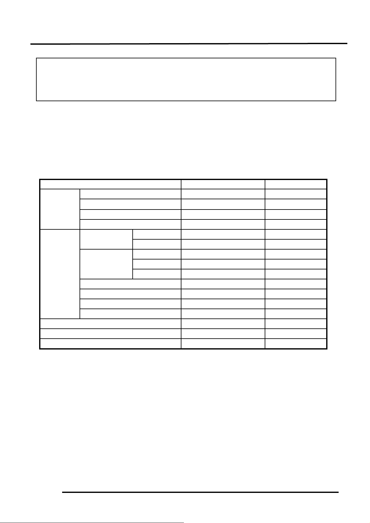
CYLINDER INSTALLATION
Install the dowel pins and a new cylinder
gasket on the crankcase.
Coat the cylinder bore, piston and piston
rings with clean engine oil.
Carefully lower the cylinder over the piston
by compressing the piston rings.
Gasket
Cylinder
Be careful not to drop foreign matters
into the crankcase.
*
• Position the piston “IN” mark
on the intake valve side.
• Place a clean shop towel in the
crankcase to keep the piston pin clip
from falling into the crankcase.
*
• Be careful not to damage or break
the piston rings.
• Stagger the ring end gaps at 120°
to the piston pin.
*
Piston Pin
Piston Pin Clip
Piston
Page 8

8. CYLINDER/PISTON
8-7
Loosely install the cylinder base bolts.
Install the cam chain guide.
Install the cylinder head. (!7-13)
Tighten the cylinder base bolts.
Insert the tab on the cam chain guide into
the cylinder groove.
*
Cylinder Base Bolt
Cam Chain Guide
 Loading...