

Page 1

13. REAR WHEEL/SWING ARM/
HYDRAULIC BRAKE
13-0
Mongoose/KXR 90/50
13
__________________________________________________________________________________
__________________________________________________________________________________
__________________________________________________________________________________
__________________________________________________________________________________
__________________________________________________________________________________
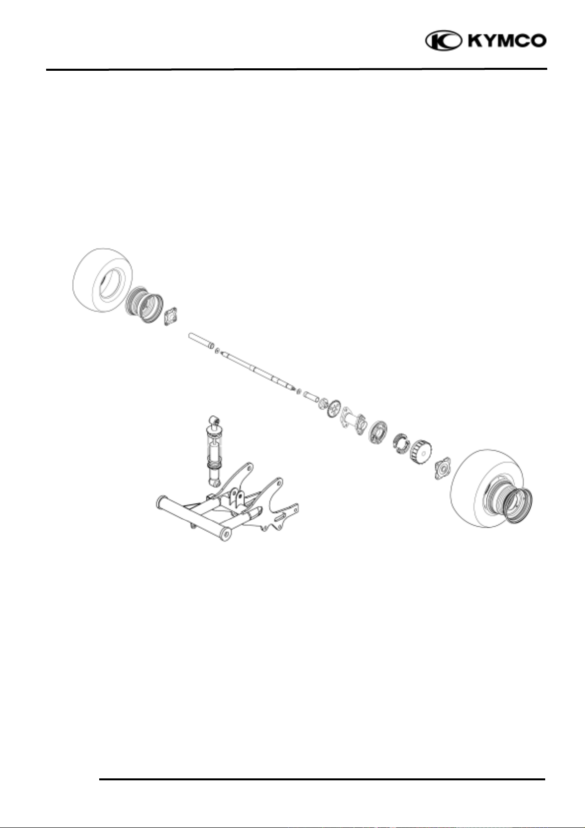
REAR WHEEL/SWING ARM/
HYDRAULIC BRAKE
__________________________________________________________________________________
SERVICE INFORMATION -------------------------------------------- 13- 2
REAR WHEEL ---------------------------------------------------------- 13- 4
REAR SWING ARM ---------------------------------------------------- 13-10
HYDRAULIC BRAKE -------------------------------------------------- 13-15
BRAKE PAD/DISK ----------------------------------------------------- 13-16
BRAKE MASTER CYLINDER ----------------------------------------- 13-17
BRAKE CALIPER------------------------------------------------------- 13-20
DRUM BRAKE ---------------------------------------------------------- 13-22
13
Page 2
13. REAR WHEEL/SWING ARM/
HYDRAULIC BRAKE
13-1
Mongoose/KXR 90/50
Page 3
13. REAR WHEEL/SWING ARM/
HYDRAULIC BRAKE
13-2
Mongoose/KXR 90/50
SERVICE INFORMATION
GENERAL INSTRUCTIONS
• During servicing, keep oil or grease off the brake drum and brake linings.
• During servicing, keep oil or grease off the brake disk and brake pads.
• Drain the brake fluid from the hydraulic brake system before disassembly.
• Contaminated brake disk or brake pads reduce stopping power. Clean the contaminated brake
disk with high-performance brake degreaser and replace the brake pads.
• Do not use brake fluid for cleaning.
• Bleed air from the brake system if the brake system is removed or the brake is soft.
• Do not allow any foreign matters entering the brake reservoir when filling the brake reservoir with
brake fluid.
• Brake fluid will damage painted, coated surfaces and plastic parts. When working with brake
fluid, use shop towels to cover and protect painted, rubber and plastic parts. Wipe off any splash
of brake fluid with a clean towel. Do not wipe the motorcycle with a towel contaminated by
brake fluid.
• Make sure to use recommended brake fluid. Use of other unspecified brake fluids may cause
brake failure.
• Inspect the brake operation before riding.
SPECIFICATIONS
Item
Standard (mm)
Service Limit (mm)
Radialæ2.0
Rear wheel
Axialæ2.0
Rear brake drum I.D
130_ 130.2
131
Brake disk thickness (disk brake)
3.8_ 4.2
3.0
Brake disk runout (disk brake)
°–
0.3
Rear brake lining thickness (drum brake)
4.5
2.0
TORQUE VALUES
Rear wheel nut 4.0_ 5.0kgf-m
Rear shock absorber upper mount bolt 3.5_ 4.5kgf-m
Rear shock absorber lower mount bolt 3.5_ 4.5kgf-m
Rear swing arm axle 6.0_ 8.0kgf-m
Rear wheel hub nut 6.0_ 8.0kgf-m
Brake arm bolt 1.8_ 2.5kgf-m
Caliper holder bolt 2.9_ 3.5kgf-m
Brake fluid tube bolt 3.0_ 4.0kgf-m
Caliper bleed valve 0.4_ 0.7kgf-m
Master cylinder bolt 1.0_ 1.4kgf-m
Rim run out
Page 4

13. REAR WHEEL/SWING ARM/
HYDRAULIC BRAKE
13-3
Mongoose/KXR 90/50
TROUBLESHOOTING
Rear wheel wobbling Poor brake performance (Drum Brake)
• Bent rim • Brake not adjusted properly
• Faulty tire • Worn brake linings
• Axle not tightened properly • Worn brake shoes at cam contacting area
• Worn brake cam
Soft rear shock absorber • Worn brake drum
• Weak shock absorber spring
• Faulty damper
Loose brake lever (Disk Brake) Tight brake lever (Disk Brake)
• Air in hydraulic brake system •Seized piston
• Brake fluid level too low •Clogged hydraulic brake system
• Hydraulic brake system leakage •Smooth or worn brake pad
Hard braking (Disk Brake) Poor brake performance (Disk Brake)
• Seized hydraulic brake system Contaminated brake pad surface
• Seized piston
Brake noise (Disk Brake)
• Contaminated brake pad surface
• Excessive brake disk run out
• Incorrectly installed caliper
• Brake disk or wheel not aligned
Poor brake performance (Disk Brake)
• Air in brake system
• Deteriorated brake fluid
• Contaminated brake pads and brake disk
• Worn brake pads
• Worn brake master cylinder piston oil seal
• Clogged brake fluid line
• Deformed brake disk
• Unevenly worn brake caliper
Page 5
13. REAR WHEEL/SWING ARM/
HYDRAULIC BRAKE
13-4
Mongoose/KXR 90/50
REAR WHEEL
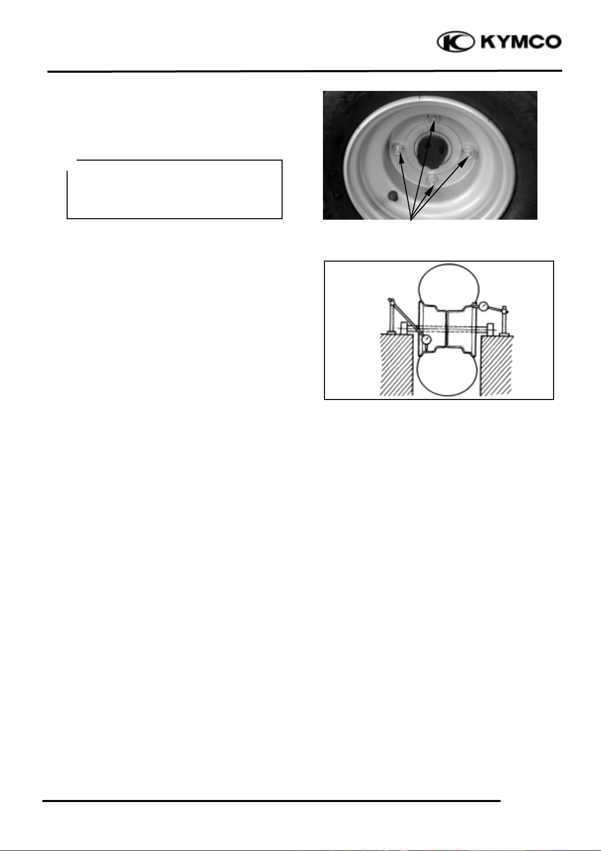
REAR WHEEL REMOVAL
Place the machine on a level place.
Remove four nuts attaching the wheel.
Remove wheel.
INSPECTION
Measure the wheel runout.
Service Limit:
Vertical: 2.0 mm
Lateral: 2.0mm
Replace wheel if out of specification.
INSTALLATION
Install the rear wheel and tighten the nuts
(wheel).
Torque: 4.0_ 5.0kgf-m
Nuts
Elevate the rear wheels by placing a
suitable stand under the rear of frame.
Support the machine securely so there is
no danger of it falling over.
°Ø
Page 6
13. REAR WHEEL/SWING ARM/
HYDRAULIC BRAKE
13-5
Mongoose/KXR 90/50
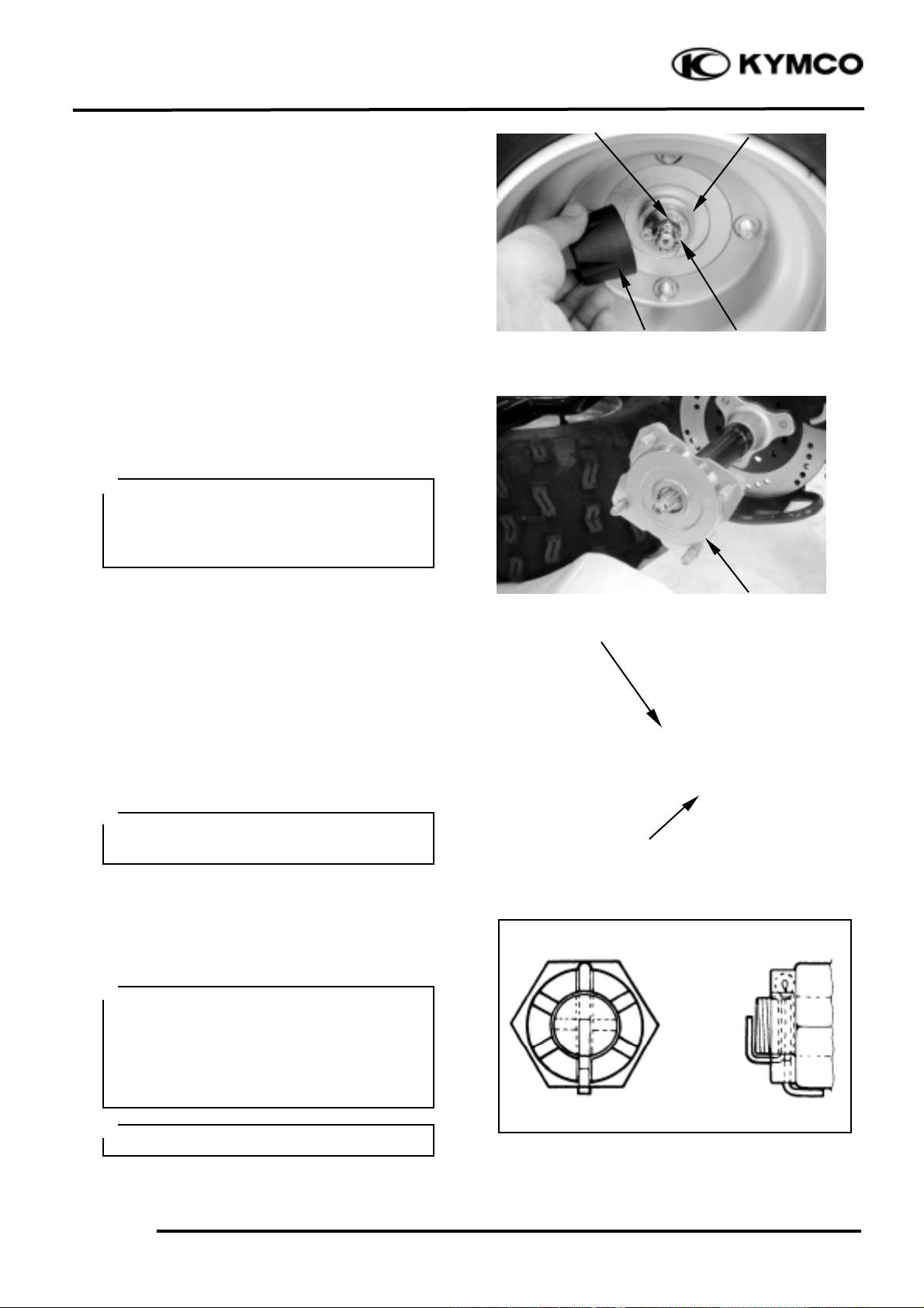
REAR WHEEL HUB REMOVAL
Remove rear wheel nuts. (See page 13-4)
Remove the wheel hub nut cover and cotter
pin.
Loosen nut attaching the wheel hub.
Remove rear wheel. (See page 13-4)
Remove wheel hub nut, washer and wheel
hub.
INSPECTION
Replace it if the wheel hub is cracks or
damage.
Replace it if splines of the wheel hub is
wear or damage.
INSTALLATION
Install wheel hub, washer and wheel hub
nut.
Torque: 6.0_ 8.0kgf-m
Install the cotter pin and band ends of cotter
pin.
Nut Cover
Cotter Pin
Washer
Nut
Wheel Hub
Splines
Wheel Hub
Do not loosen the axle nut after torque
tightening. If the axle nut groove is not
aligned with the cotter pin hole, align
groove with the hole by tightening up on
the axle nut.
°Ø
Always use a new cotter pin.
°Ø
Apply grease onto the splines of the
wheel hub.
°Ø
Elevate the rear wheels by placing a
suitable stand under the rear of frame.
Support the machine securely so there is
no danger of it falling over.
°Ø
Page 7
13. REAR WHEEL/SWING ARM/
HYDRAULIC BRAKE
13-6
Mongoose/KXR 90/50
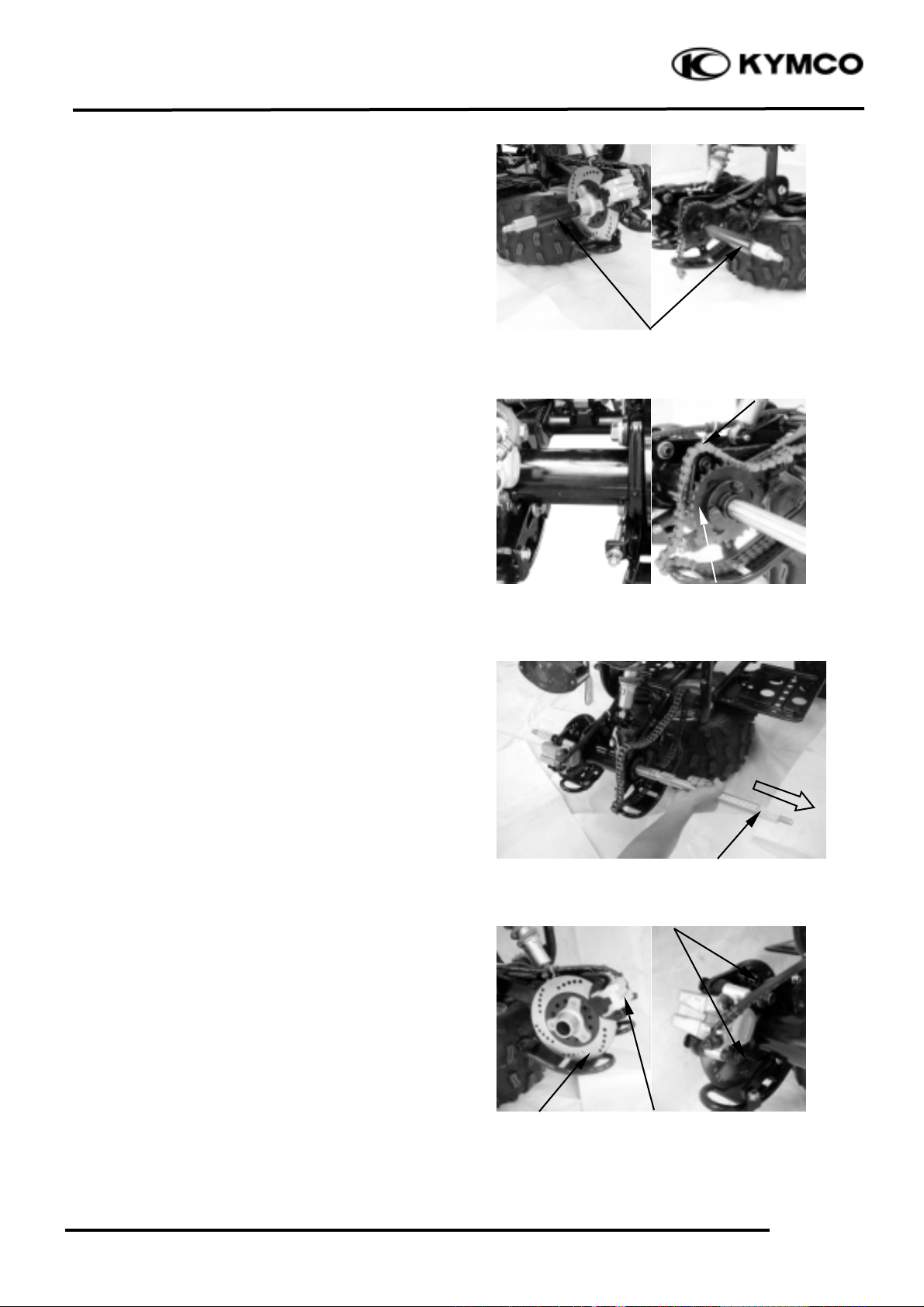
REAR AXLE REMOVAL
Remove the rear wheel hub of the both rear
wheels. (See page 13-5).
Remove the collars on the rear axle right and
left side.
Relax the drive chain. (Refer to the “DRIVE
CHAIN SLACK ADJUSTMENT” section
in chapter 3.)
Remove driven sprocket.
Remove the rear axle from right side.
Remove the two bolts and caliper and then
remove brake disk.
Collars
Driven Sprocket
Rear Axle
Bolts
Brake Disk
Bolts
Drive Chain
Caliper
Page 8
13. REAR WHEEL/SWING ARM/
HYDRAULIC BRAKE
13-7
Mongoose/KXR 90/50
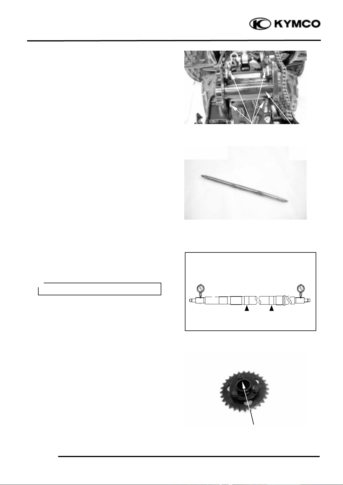
Remove the four bolts and rear axle hub.
INSPECTION
Replace it if the rear axle is scratched
(excessively) or damage.
Replace if splines and threads of the rear
axle is wear or damage.
Measure the rear axle run out.
Service limit: less than 1.5mm
Replace if it is out of specification.
Replace it if the driven sprocket is cracks or
damage.
Replace it if splines of the driven sprocket
is wear or damage.
Splines
Do not attempt to straighten a bent axle.
°Ø
Bolts
Axle Hub
Page 9

13. REAR WHEEL/SWING ARM/
HYDRAULIC BRAKE
13-8
Mongoose/KXR 90/50
Inspect the driven sprocket.
Replace sprocket if more than 1/4 teeth
wear or bent teeth.
Replace it if the brake disk is cracks or
damage.
Replace it if splines of the brake disk is
wear or damage.
Inspect rear axle hub.
Replace it if bearing allow play in the axle
hub or the bearing turns roughly.
Replace it if oil seal is wear or damage.
Replace it if rear axle hub is cracks, bend or
damage.
Bearing and oil seal replacement steps:
Clean the outside of the rear axle.
Remove the oil seal by a flat-head screw
driver.
Remove the bearing by a general bearing
puller.
Install the new bearings and oil seal by
reversing the previous steps.
Brake Drum Cover
Splines
Oil Seal
Place a wood block against the outer
edge to protect this edge.
°Ø
Do not strike the center race or balls of
the bearing.
Contact should be made only with the
outer race.
°Ø
Distance Collar
Bearings
Oil Seal
Page 10

13. REAR WHEEL/SWING ARM/
HYDRAULIC BRAKE
13-9
Mongoose/KXR 90/50
INSTALLATION
Reverse the “REMOVAL” procedures.
Install the rear axle hub.
Install the rear axle.
Install brake disk, driven sprocket and
collars.
Install wheel hub (see page 13-5) and rear
wheel (see page 13-4).
Adjust drive chain slack. (Refer to the
“DRIVE CHAIN SLACK
ADJUSTMENT” section in chapter 3.)
Approximately: 10~20 mm
At this time, the rear axle hub should not
be tightened completely.
Final tightening is done after the chain
slack adjustment.
°Ø
Apply grease onto the oil seal lips,
bearings and bushes.
°Ø
Page 11

13. REAR WHEEL/SWING ARM/
HYDRAULIC BRAKE
13-10
Mongoose/KXR 90/50
REAR SWING ARM
REMOVAL
Place the machine on a level place.
Elevate the rear wheels by placing a suitable
stand under the rear of frame.
Remove the rear wheels, rear hubs, rear axle
and axle hub. (Refer to the “REAR
WHEEL” section in chapter 13.)
Remove the lower bolt attaching the rear
shock absorber.
Remove the upper bolt and then remove the
shock absorber.
INSPECTION
Check the tightening torque of the pivot
shaft (swing arm) securing nut.
Torque: 6.0_ 8.0kgf-m
Lower Bolt
Support the machine securely so there is
no danger of it falling over.
°Ø
When removing the lower bolt, hold the
swing arm so that it does not drop
downwards when the bolt is removed.
°Ø
Upper Bolt
Securing Nut
Page 12

13. REAR WHEEL/SWING ARM/
HYDRAULIC BRAKE
13-11
Mongoose/KXR 90/50
Check the swing arm side play by moving it
from side to side.
If side play noticeable, check the inner
collar, bushing and thrust cover.
Check the swing arm vertical movement by
moving it up and down.
If vertical movement is tight, binding or
rough, to check the inner collar, bushing and
thrust cover.
INSPECTION
Inspect the shock absorber rod.
Replace the shock absorber assembly if
bends or damage.
Inspect the shock absorber.
Replace the shock absorber assembly if oil
leaks
Inspect the spring.
Replace the shock absorber assembly if
fatigue.
Move the spring up and down.
Page 13

13. REAR WHEEL/SWING ARM/
HYDRAULIC BRAKE
13-12
Mongoose/KXR 90/50
REAR SWING ARM REMOVAL
Remove the nut and pivot shaft, then
remove swing arm.
Remove the three bolts and chain guard.
Remove the drive chain.
Remove thrust covers and collar.
Nut
Thrust Covers
Swing Arm
Bolts
Drive Chain
Chain Guard
Page 14

13. REAR WHEEL/SWING ARM/
HYDRAULIC BRAKE
13-13
Mongoose/KXR 90/50
INSPECTION
Roll the axle on a flat surface to inspect the
pivot shaft.
Replace it if bends.
Inspect the swing arm.
Replace it if crack, bend or damage.
Inspect the thrust cover, chain guide, collar
and bush.
Replace them if wear or damage.
Inspect the drive chain stiffness.
Clean and lubricate or replace it if stiff.
CLEAN
Place it in kerosene, and brush off as much
dirt as possible. Then remove the chain from
the kerosene and dry the chain.
Do not attempt to straighten a bent axle.
°Ø
Bushes
Thrust Covers
Thrust Covers
Collar
Chain Guide
Page 15

13. REAR WHEEL/SWING ARM/
HYDRAULIC BRAKE
13-14
Mongoose/KXR 90/50
INSTALLATION
Reverse the “REMOVAL” procedure.
Apply grease onto the collar, bush, pivot
shaft and thrust cover.
Install the swing arm and tightening the nut.
Torque: 6.0_ 8.0kgf-m
Install the shock absorber and tightening the
bolts.
Torque: 3.5_ 4.5kgf-m
This machine has a drive chain with small
rubber O-rings between the chain plates.
Steam cleaning, high-pressure washes,
and certain solvent can damage these Orings. Use only kerosene to clean the
drive chain.
°Ø
O-ring
Page 16

13. REAR WHEEL/SWING ARM/
HYDRAULIC BRAKE
13-15
Mongoose/KXR 90/50
HYDRAULIC BRAKE
BRAKE FLUID CHANGE
Place the machine on a level place and set
the handlebar upright.
Remove the two screws attaching the brake
fluid reservoir cap.
Connect a transparent hose to the brake
caliper bleed valve and then loosen the bleed
valve nut.
Use a syringe to draw the brake fluid out
through the hose.
BRAKE FLUID REFILLING
Connect a transparent hose and syringe to
the brake caliper bleed valve and then loosen
the bleed valve nut.
Fill the brake reservoir with brake fluid and
use the syringe to draw brake fluid into it
until there is no air bubbles in the hose.
Then, tighten the bleed valve nut.
Torque: 0.4_ 0.7kg-m
Recommended Brake Fluid: DOT-4
Bleed Valve
Brake Reservoir
Bleed Valve
• When drawing brake fluid with the
syringe, the brake fluid level should be
kept over 1/2 of the brake reservoir
height.
• Use only the recommended brake fluid.
*
Screw
Use shop towels to cover plastic parts
and coated surfaces to avoid damage
caused by splash of brake fluid.
*
Page 17

13. REAR WHEEL/SWING ARM/
HYDRAULIC BRAKE
13-16
Mongoose/KXR 90/50
BRAKE SYSTEM BLEEDING
Connect a transparent hose to the bleed
valve and fully apply the brake lever after
continuously pull it several times. Then,
loosen the bleed valve nut to bleed air from
the brake system. Repeat these steps until
the brake system is free of air.
BRAKE PAD/DISK
BRAKE PAD REPLACEMENT
Remove the two bolts attaching the brake
caliper holder.
Remove the brake caliper.
Push the brake caliper holder and then
remove brake pad.
Remove the other brake pad.
ASSEMBLY
Assemble the brake pads in the reverse
order of removal.
Brake Lever
Bleed Valve
Brake Caliper Holder
Pad Spring
Bolts
Brake Bad
Brake Bad
Make sure the pad spring has fitted.
*
When bleeding air from the brake system,
the brake fluid level should be kept over
1/2 of the brake reservoir height.
*
The brake pads can be replaced without
removing the brake fluid tube.
*
Page 18

13. REAR WHEEL/SWING ARM/
HYDRAULIC BRAKE
13-17
Mongoose/KXR 90/50
BRAKE DISK
Measure the brake disk thickness.
Service Limit: 3.0mm
Measure the brake disk run out.
Service Limit: 0.3mm
BRAKE MASTER CYLINDER
REMOVAL
Drain the brake fluid from the hydraulic
brake system.
Remove the two master cylinder holder
bolts and remove the master cylinder.
Do not splash brake fluid onto any
rubber, plastic and coated parts. When
working with brake fluid, use shop
towels to cover these parts.
*
When removing the brake fluid tube bolt,
be sure to place towels under the tube
and plug the tube end to avoid brake fluid
leakage and contamination.
*
Fluid Tube Bolt
Bolts
Page 19

13. REAR WHEEL/SWING ARM/
HYDRAULIC BRAKE
13-18
Mongoose/KXR 90/50
Master Cylinder
Spring
Snap Ring Pliers
Main
Piston
Snap Ring
DISASSEMBLY
Remove the piston rubber cover and snap
ring from the brake master cylinder.
Remove the washer, main piston and spring
from the brake master cylinder.
Clean the inside of the master cylinder and
brake reservoir with brake fluid.
I INSPECTION
Check the cylinder inside wall, and spring
for scratch, corrosion or other abnormal
condition.
If any abnormal condition is found, replace
the inner parts or master cylinder.
Page 20

13. REAR WHEEL/SWING ARM/
HYDRAULIC BRAKE
13-19
Mongoose/KXR 90/50
Fluid Tube Bolt
Sealing Washer
“UP” Mark
ASSEMBLY
Before assembly, apply brake fluid to all
removed parts.
Install the main piston and snap ring.
Install the rubber cover.
Install the brake lever.
Install the brake fluid tube with the bolt and
two sealing washers.
Fill the brake reservoir with recommended
brake fluid to the upper level.
Bleed air from the hydraulic brake system.
(See page 13-15.)
Place the brake master cylinder on the
handlebar and install the master cylinder
holder with the “UP” mark facing up,
aligning the tab on the holder with the hole
in the handlebar.
First tighten the upper bolt and then tighten
the lower bolt.
Torque: 1.0_ 1.4kg-m
• During assembly, the main piston and
spring must be installed as a unit
without exchange.
• When assembling the piston, soak the
cups in brake fluid for a while.
• Install the cups with the cup lips facing
the correct direction.
°Ø
Page 21

13. REAR WHEEL/SWING ARM/
HYDRAULIC BRAKE
13-20
Mongoose/KXR 90/50
Brake Caliper Holder
Piston Oil Seals
BRAKE CALIPER
DISASSEMBLY
Remove the brake caliper, brake pads and
pad spring. (See page 13-16)
Place a clean container under the brake
caliper and disconnect the brake fluid tube
from the brake caliper.
DISASSEMBLY
Remove the brake caliper holder from the
brake caliper.
Remove the pistons from the brake caliper.
Use compressed air to press out the pistons
through the brake fluid inlet opening and
place a shop towel under the caliper to
avoid contamination caused by the removed
pistons.
Push the piston oil seals inward to remove
them.
Clean each oil seal groove with brake fluid.
Be careful not to splash brake fluid on
any coated surfaces.
*
Be careful not to damage the piston
surface.
*
Page 22

13. REAR WHEEL/SWING ARM/
HYDRAULIC BRAKE
13-21
Mongoose/KXR 90/50
INSPECTION
Inspect the caliper cylinder wall and piston
surface for scratch, corrosion or other
damages.
If any abnormal condition is noted, replace
the caliper.
ASSEMBLY
Clean all removed parts.
Apply silicon grease to the pistons and oil
seals. Lubricate the brake caliper cylinder
inside wall with brake fluid.
Install the oil seals and then install the brake
caliper pistons with the grooved side facing
out.
Wipe off excessive brake fluid with a clean
shop towel. Apply silicon grease to the
brake caliper holder pin and caliper inside.
Install the brake caliper holder.
Install the piston with its outer end
protruding 3_ 5mm beyond the brake
caliper.
*
Page 23

13. REAR WHEEL/SWING ARM/
HYDRAULIC BRAKE
13-22
Mongoose/KXR 90/50
Washers
Fluid Tube Bolt
Aligning The Fluid Tube With Groove
Brake Drum
Brake Shoes
INSTALLATION
Connect the brake fluid tube to the brake
caliper, aligning the fluid tube with groove in
the caliper and tighten the fluid tube bolt.
Torque: 3.0_ 4.0kg-m
Add the recommended brake fluid into the
brake reservoir and bleed air from the brake
system. (
Refer to 13-15.
)
Install the brake caliper onto rear axle hub
and tighten the bolts.
Torque: 2.9_ 3.5kg-m
DRUM BRAKE
REMOVAL
Remove wheel hub and axle hub. (See page
13-5)
Remove brake drum.
Remove brake shoes.
Page 24

13. REAR WHEEL/SWING ARM/
HYDRAULIC BRAKE
13-23
Mongoose/KXR 90/50
INSPECTION
Inspect the inner surface of the brake drum
is scratches, polish brake drum lightly and
evenly with emery cloth.
Measure the inside diameter of the brake
drum.
Service limit: 131mm
Replace it if it is out of specification.
Measure the front brake lining thickness
(A).
Service limit: 2.0mm replace it if below
INSTALLATION
Reverse the “REMOVE” procedures.
 Loading...