

Page 1
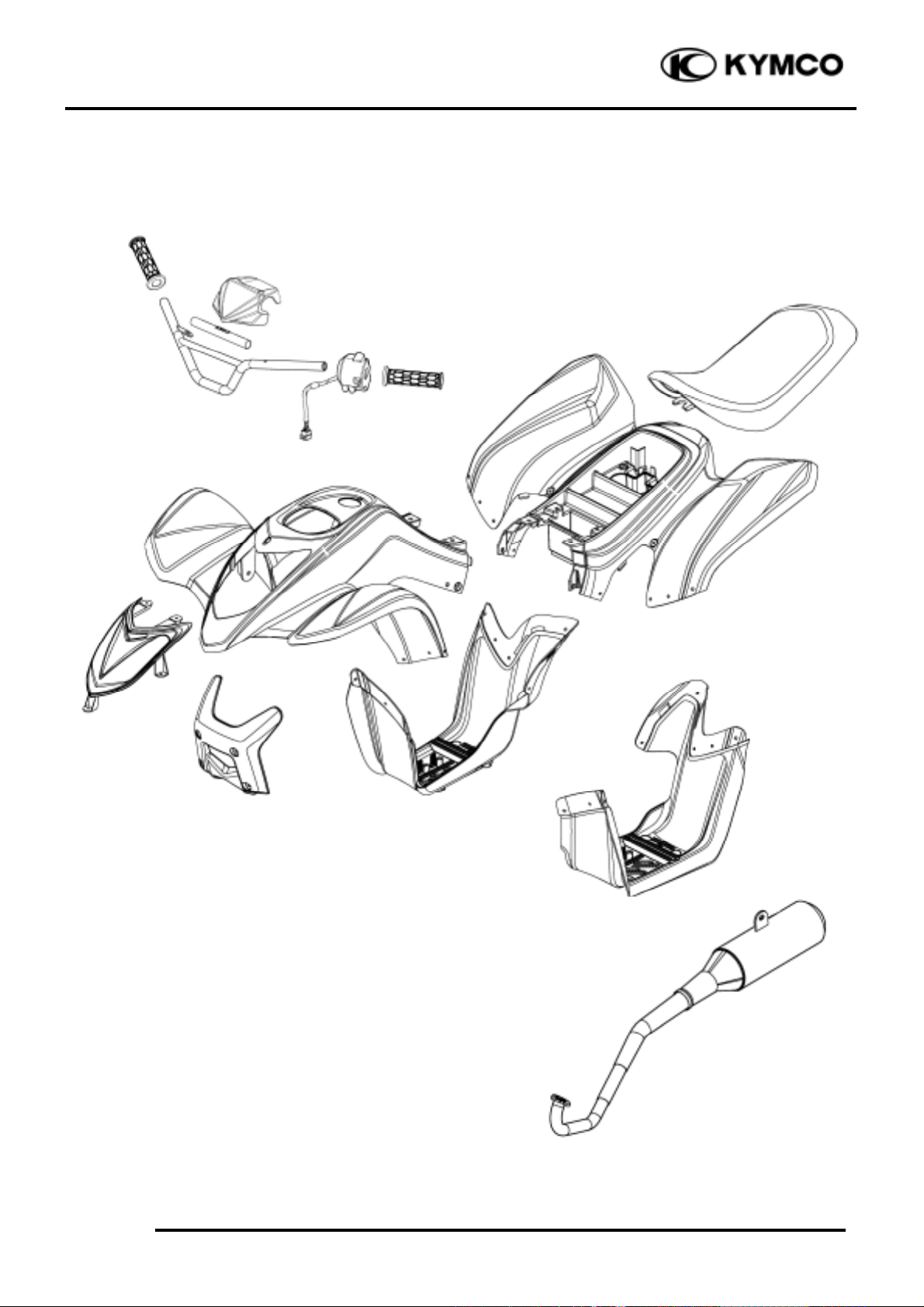
2. FRAME COVERS/EXHAUST MUFFLER
2-0
Mongoose/KXR 90/50
2
__________________________________________________________________________________
__________________________________________________________________________________
__________________________________________________________________________________
__________________________________________________________________________________
__________________________________________________________________________________
FRAME COVERS/EXHAUST MUFFLER
__________________________________________________________________________________
SERVICE INFORMATION -------------------------------------------- 2- 2
FRAME COVERS ------------------------------------------------------- 2- 3
EXHAUST MUFFLER REMOVAL ----------------------------------- 2- 7
TAILLIGHT BULB ----------------------------------------------------- 2- 8
2
Page 2
2. FRAME COVERS/EXHAUST MUFFLER
2-1
Mongoose/KXR 90/50
Page 3
2. FRAME COVERS/EXHAUST MUFFLER
2-2
Mongoose/KXR 90/50
SERVICE INFORMATION
GENERAL INSTRUCTIONS
• When removing frame covers, use special care not to pull them by force because the cover joint
claws may be damaged.
• Make sure to route cables and harnesses according to the Cable & Harness Routing.
TORQUE VALUES
Exhaust muffler lock bolt 3.2_ 3.8kgf-m
Exhaust muffler lock nut 1.8_ 2.2kgf-m
TROUBLESHOOTING
Noisy exhaust muffler
• Damaged exhaust muffler
• Exhaust muffler joint air leaks
Lack of power
• Caved exhaust muffler
• Exhaust muffler air leaks
• Clogged exhaust muffler
Page 4

2. FRAME COVERS/EXHAUST MUFFLER
2-3
Mongoose/KXR 90/50
FRAME COVERS
HANDLEBAR COVER REMOVAL
Remove the two screws attaching the
handlebar cover.
Disconnect the oil level indicator leads
(Mongoose/KXR 50).
Remove the handlebar cover.
INSTALLATION
Reverse the “HANDLEBAR COVER
REMOVAL” procedures.
SEAT REMOVAL
To remove the seat, pull upward the seat
lock lever and pull up the seat at the rear.
To install the seat, align the tabs on the seat
with the grommets on the frame and press
the seat down until it locks.
HANDLEBAR REMOVAL
Remove handlebar cover. (See page 2-3)
Remove the rear brake master cylinder
attaching bolts (disk brake).
Disconnect the rear brake cable (drum
brake).
Disconnect the handlebar switch coupler
and lead (under front fender).
Bolts
Handlebar Cover
Seat Lock Lever
Seat
Make sure that the seat is securely fitted.
°Ø
Bolts
Handlebar Switch Coupler and Lead
Page 5

2. FRAME COVERS/EXHAUST MUFFLER
2-4
Mongoose/KXR 90/50
Disconnect the front brake cables.
Disconnect the remote stop switch and
front brake stop switch leads.
Remove the two screws and speed limiter
cover.
Disconnect the throttle cable.
Remove the two bolts and handlebar cover
holder.
Remove the four bolts and upper handlebar
holders.
Remove the handlebar.
INSTALLATION
Reverse the “HANDLEBAR REMOVAL”
procedures. (See page 12-13)
Refer to the “BRAKE LEVER FREE
PLAY” section in the chapter 3 to adjust
brake lever free play.
°Ø
Front Brake Cables
Remote Engine Stop
Switch Leads
Front Brake Stop
Switch Leads
Screws
Throttle Cable
Bolts
Bolts
Page 6

2. FRAME COVERS/EXHAUST MUFFLER
2-5
Mongoose/KXR 90/50
FRONT FENDER REMOVAL
Remove the seat. (See page 2-3)
Remove the handlebar. (See page 2-3)
Remove the six screws and nuts attaching
the front fender and right/left foot boards.
Remove the four screws and two nuts
attaching the front fender and rear fender at
the right/left side.
Remove the two bolts attaching front fender
at the right/left side.
Remover the fuel filler cap.
Remove the front fender and disconnect the
ignition switch coupler.
During removal, do not pull the joint
claws forcedly to avoid damage.
°Ø
After remove, be sure to tighten the fuel
filler cap.
°Ø
Screws
Screws
Screws
Screws
Bolts
Fuel Filler Cap
Ignition Switch Coupler
Page 7

2. FRAME COVERS/EXHAUST MUFFLER
2-6
Mongoose/KXR 90/50
INSTALLATION
Reverse the “FRONT FENDER
REMOVAL” procedures.
REAR FENDER REMOVAL
Remove the front fender. (See page 2-5)
Remove the battery. (See page 14-4)
Remove the starter relay and CDI unit.
Remove the ten screws attaching the rear
fender and foot boards at the right/left side.
Remove the two screws attaching the rear
fender at the rear.
Remove the three bolts attaching the rear
fender at the center and then remove the rear
fender.
After remove, be sure to tighten the fuel
filler cap.
°Ø
Starter Relay
Ignition Unit
Screws
Screws
Screws
Bolts
Page 8

2. FRAME COVERS/EXHAUST MUFFLER
2-7
Mongoose/KXR 90/50
FOOT BOARD REMOVAL
Remove front fender. (See page 2-5)
Remover rear fender. (See page 2-6)
Remove the four bolts attaching the
right/left foot board.
FRONT CARRIER REMOVAL
Remove the four bolts attaching front carrier
at the right/left side.
EXHAUST MUFFLER
REMOVAL
Remove the two nuts attaching the exhaust
pipe and cylinder head.
Remove the three bolts attaching the exhaust
muffler, then remove the exhaust muffler.
Bolts
Bolts
Nuts
Bolts
Page 9

2. FRAME COVERS/EXHAUST MUFFLER
2-8
Mongoose/KXR 90/50
Inspect the gasket.
If the exhaust gas leaks, the gasket should be
replaced.
Install by reversing the removal sequence.
Torque:
Exhaust muffler lock bolt: 3.2_ 3.8kgf-m
Exhaust muffler lock nut: 1.8_ 2.2kgf-m
TAILLIGHT BULB
REMOVAL
Remove the two screws and taillight lens.
Turn bulb and remove it.
Be sure to install a new exhaust gasket.
°Ø
Gasket
Scresw
Bulb
 Loading...