

Page 1

5. FUEL SYSTEM
5-0
Mongoose/KXR 90/50
5
__________________________________________________________________________________
__________________________________________________________________________________
__________________________________________________________________________________
__________________________________________________________________________________
__________________________________________________________________________________
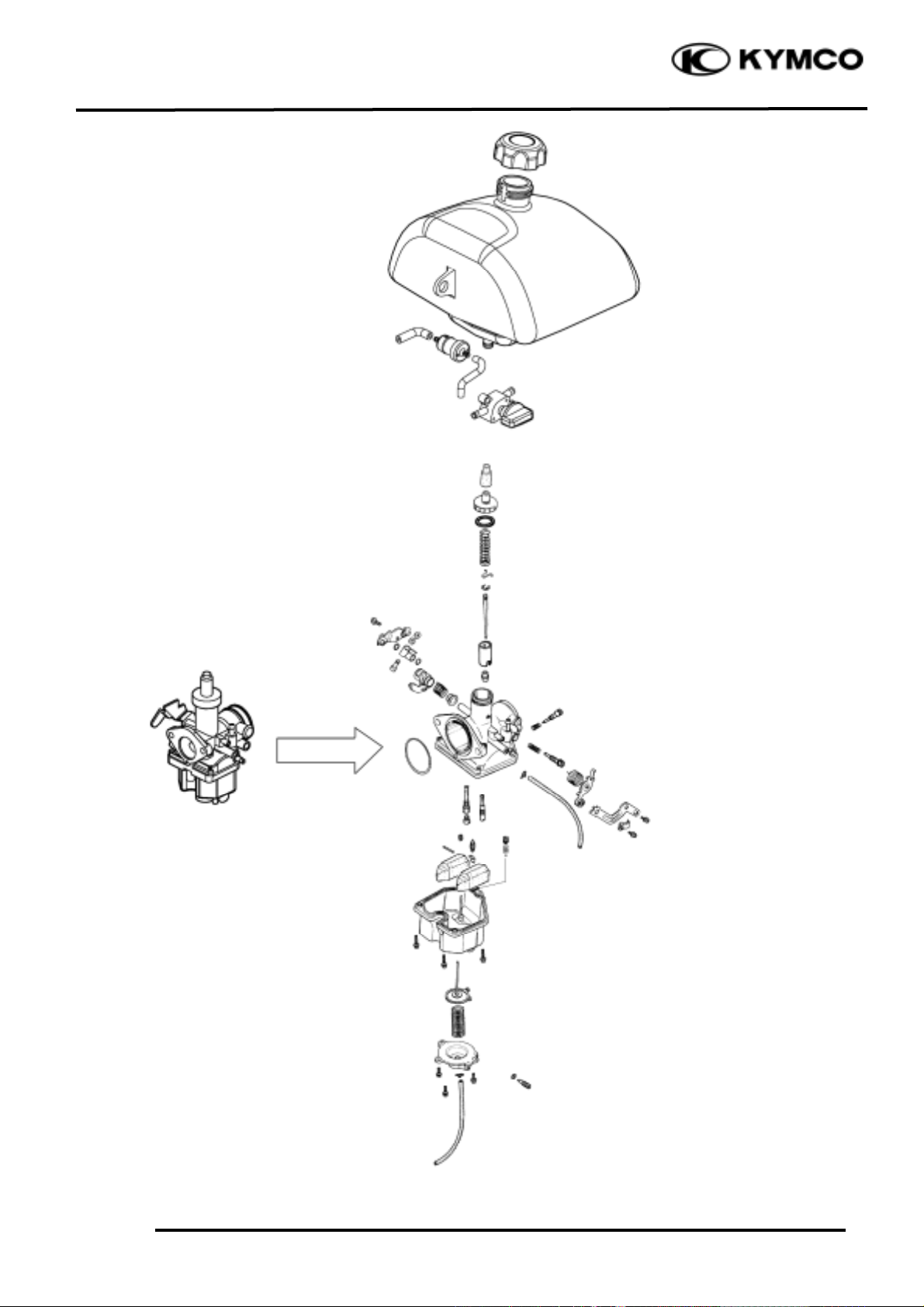
FUEL SYSTEM
__________________________________________________________________________________
SERVICE INFORMATION -------------------------------------------- 5- 2
FUEL TANK------------------------------------------------------------- 5- 4
FUEL VALVE REMOVAL -------------------------------------------- 5- 4
THROTTLE VALVE ----------------------------------------------------- 5- 7
AIR CLEANER ---------------------------------------------------------- 5- 9
CARBURETOR ---------------------------------------------------------- 5-11
REED VAVLE (Mongoose/KXR 50) ---------------------------------- 5-16
5
Page 2
5. FUEL SYSTEM
5-1
Mongoose/KXR 90/50
Page 3
5. FUEL SYSTEM
5-2
Mongoose/KXR 90/50
SERVICE INFORMATION
GENERAL INSTRUCTIONS
• Do not bend or twist control cables. Damaged control cables will not operate smoothly.
• When disassembling fuel system parts, note the locations of O-rings. Replace them with new
ones during reassembly.
• Before float chamber disassembly, loosen the drain screw to drain the residual gasoline into a
clean container.
• After the carburetor is removed, plug the intake manifold side with a clean shop towel to prevent
foreign matters from entering.
• When cleaning the carburetor air and fuel jets, the O-rings and diaphragm must be removed first to
avoid damage. Then, clean with compressed air.
• When the machine is not used for over one month, drain the residual gasoline from the float
chamber to avoid erratic idling and clogged slow jet due to deteriorated fuel.
SPECIFICATIONS
Item
Standard(Mongoose/KXR 90)
Standard(Mongoose/KXR 50)
Type
PB
PB
Venturi dia.
f14
f14
Slow jet No.
#35
#38
Main jet No.
#100
#80
Adjust method
Piston
Piston
Idle speed
1700±100rpm
2000±100rpm
Throttle grip free play
1_ 4mm
1_ 4mm
Float level
8.0mm
8.0mm
Air screw opening
1±1/4
1±1/4
Gasoline is very dangerous. When working with gasoline, keep sparks and flames away
from the working area.
Gasoline is extremely flammable and is explosive under certain conditions. Be sure to work
in a well-ventilated area.
Page 4

5. FUEL SYSTEM
5-3
Mongoose/KXR 90/50
SPECIAL TOOL
Float level gauge
TROUBLESHOOTING
Engine cranks but won’t start Engine lacks power
• No fuel in tank • Clogged air cleaner
• No fuel to carburetor • Faulty carburetor
• Cylinder flooded with fuel • Faulty ignition system
• No spark at plug
• Clogged air cleaner Lean mixture
• Intake air leak • Clogged carburetor fuel jets
• Improper throttle operation • Float level too low
• Intake air leak
Engine idles roughly, stalls or runs poorly • Clogged fuel tank cap breather hole
• Faulty auto bystarter • Bent, kinked or restricted fuel line
• Ignition malfunction
• Faulty carburetor Rich mixture
• Poor quality fuel • Float level too high
• Lean or rich mixture • Clogged air jets
• Incorrect idle speed • Clogged air cleaner
Misfiring during acceleration
• Faulty ignition system
• Faulty carburetor
Backfiring at deceleration
• Float level too low
• Incorrectly adjusted carburetor
• Faulty exhaust muffler
Page 5
5. FUEL SYSTEM
5-4
Mongoose/KXR 90/50
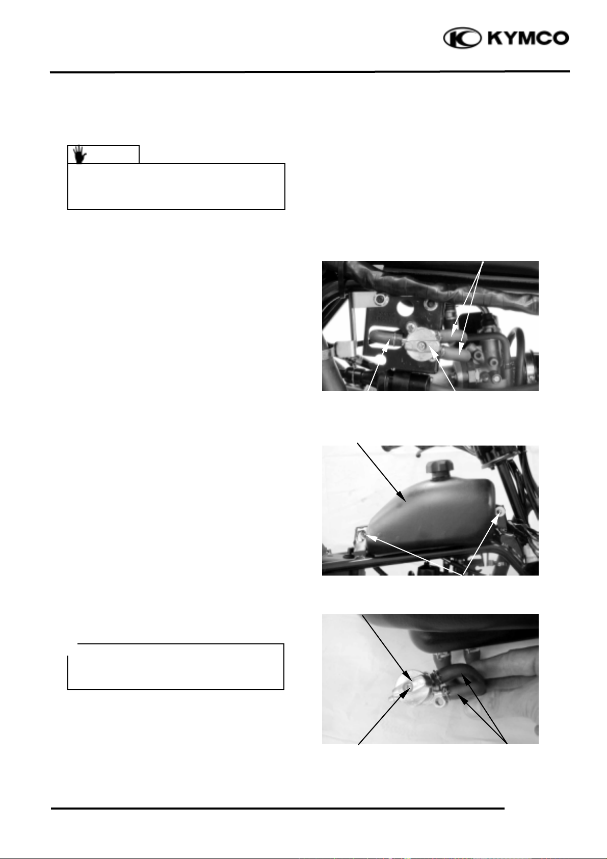
FUEL TANK
REMOVAL
Remove front fender (See page 2-5).
Switch the fuel valve “OFF”.
Disconnect the fuel outlet tube from fuel
valve.
Remove two screws attaching the fuel valve
and holder.
Remove the two bolts and then remove the
fuel tank.
INSTALLATION
Reverse the “FUEL TANK REMOVAL”
procedures.
FUEL VALVE
REMOVAL
Remove the screw and then remove control
switch.
Disconnect all fuel tubes and then remove
fuel valve.
Warning
Fuel Tank
Screw
Fuel Valve
Bolts
Fuel Outlet Tube
• Keep sparks and flames away from the
work area.
• Wipe off any spilled gasoline.
Control Switch
Fuel Tubes
Screws
• Keep sparks and flames away from the
work area.
• Drain gasoline into a clean container.
°Ø
Page 6
5. FUEL SYSTEM
5-5
Mongoose/KXR 90/50
DISASSEMBLY
Remove the two screws on the retaining ring
and then remove retaining ring.
Remove the washer and control shaft.
Remove the rubber gasket from the fuel valve
body.
INSPECTION
Inspect the fuel valve body for dirt and clog.
Clean if necessary.
Replace the rubber gasket with new ones if
they are damaged or deteriorated.
Replace the O-rings with new ones if they
are damaged or deteriorated.
ASSEMBLY
Reverse the “DISASSEMBLY” procedures.
Install rubber gasket, control shaft, washer
and retaining ring.
Fuel Valve Body
Control Shaft
Rubber Gasket
Retaining Ring
Washer
Screws
Control Shaft
O-ring
• Aligning the tab on the control shaft
with the outlet duct in the fuel valve
body.
• Aligning the tab on the retaining ring
with the outlet duct in the fuel valve
body.
°Ø
Tab
Outlet Duct
Outlet Duct
Tab
Page 7

5. FUEL SYSTEM
5-6
Mongoose/KXR 90/50
INSTALLATION
Reverse the “FUEL VALVE REMOVEAL”
procedures.
Connect all fuel tube.
Reserve Fuel Tube
Main Fuel Tube
Outlet Fuel Tube
Page 8

5. FUEL SYSTEM
5-7
Mongoose/KXR 90/50
THROTTLE VALVE
DISASSEMBLY
Remove the fuel tank. (Refer to “FUEL
TANK” section in the chapter 5)
Remove the carburetor cap.
Pull out the throttle valve.
Compress the spring to disconnect the
throttle cable by hand.
Remove the spring from the throttle valve
Carburetor Cap
Spring
Throttle Valve
Throttle Cable
Page 9

5. FUEL SYSTEM
5-8
Mongoose/KXR 90/50
Pry off the needle retainer and remove the jet
needle.
Check the throttle valve and jet needle for
wear or damage.
ASSEMBLY
Reverse the “DISASSEMBLY” procedures.
Install the throttle valve into the carburetor
body.
Throttle Valve
Needle Retainer
Jet Needle
Align the groove in the throttle valve
with the throttle stop screw on the
carburetor body.
°Ø
Throttle Stop Screw
Groove
Page 10

5. FUEL SYSTEM
5-9
Mongoose/KXR 90/50
AIR CLEANER (Mongoose/KXR
90)
CLEANING
Refer to “AIR CLEANER” section in the
chapter 3.
REMOVAL
Remove front fender. (See page 2-5)
Disconnect the oil recycle tube from cylinder
head and frame.
Remove the bolt at the air cleaner left side.
Loosen the screw at the band and remove bolt at
the air cleaner right side, then remove air cleaner.
INSTALLATION
Reverse the “REMOVAL” procedures.
Oil Recycle Tube
Bolt
Bolt
Screw
Band
Page 11

5. FUEL SYSTEM
5-10
Mongoose/KXR 90/50
AIR CLEANER (Mongoose/KXR
50)
CLEANING
Refer to “AIR CLEANER” section in the
chapter 3.
REMOVAL
Remove front fender. (See page 2-5)
Disconnect the air inlet hose from the frame.
Remove the bolt at the air cleaner left side.
Loosen the screw at the band and remove bolt at
the air cleaner right side, then remove air cleaner.
INSTALLATION
Reverse the “REMOVAL” procedures.
Air Inlet Hose
Bolt
Bolt
Screw
Page 12

5. FUEL SYSTEM
5-11
Mongoose/KXR 90/50
CARBURETOR
REMOVAL
Remove the fuel tank, carburetor cap and air
filter. (Refer to chapter 5)
Loosen the drain plug to drain the gasoline
from the float chamber.
Disconnect the fuel tube from carburetor and
auto bystarter leads.
Remove the two bolts (nuts) attaching
carburetor, then remove carburetor and
insulator.
INSTALLATION
Reverse the “REMOVAL” procedures.
Check the carburetor insulator and O-rings
for wear or damage.
Fuel Drain Plug
• Keep sparks and flames away from the
work area.
• Drain gasoline into a clean container.
°Ø
Bolts
Fuel Tube
Auto Bystarter
Insulator
When installation, do not allow foreign
particles to enter the carburetor.
°Ø
When installation, be sure the insulator
O-ring face the intake manifold.
°Ø
Insulator
Insulator O-ring
O-ring
Page 13

5. FUEL SYSTEM
5-12
Mongoose/KXR 90/50
DISASSEMBLY
Remove auto bystarter cap.
Remove the two screws and then remove
auto bystarter and plate.
Remove the three float chamber screws and
remove the float chamber.
Pull out the float pin, then remove float and
float valve.
Remove the main jet, needle jet holder, and
needle jet.
Remove the slow jet.
Remove the air screw and throttle stop
screw.
Auto Bystarter Cap
Screws
Float Valve
Float
Main Jet/Needle Jet
Holder/Needle Jet
Auto Bystarte
Screws
Float Chamber
Float Pin
Throttle Stop Screw
Slow Jet
Air Screw
Page 14

5. FUEL SYSTEM
5-13
Mongoose/KXR 90/50
CAUTIONS!
ASSEMBLY
Reverse the “DISASSEMBLY” procedures.
• Be careful not to damage the jets and
jet holder when removing them.
• Before removal, turn the throttle stop
screw and air screw in and count the
number of turns until they seat lightly
and then make a note of this.
• Do not force the screw against its seat
to avoid seat damage.
• Be sure to install the O-ring in the
reverse order of removal.
°Ø
Needle Jet
Throttle Stop Screw
Spring
Air Screw
Spring
Washer
O-ring
Main Jet
Needle Jet Holder
Slow Jet
• When installing the air screw, return it
to the original position as noted during
removal
• Refer to the “CARBURETOR IDLE
SPEED” section in chapters to perform
the idle speed adjustment.
• After the carburetor is installed, be sure
to perform the Exhaust Emission Test.
°Ø
Page 15

5. FUEL SYSTEM
5-14
Mongoose/KXR 90/50
CARBURETOR CLEANING
Blow compressed air through all passages of
the carburetor body.
FLOAT/FLOAT VALVE INSPECTION
Inspect the float valve seat for wear or
damage.
Inspect the float for damage or fuel level
inside the float chamber.
FUEL RESERVOIR O-RING CHECK
Remove the O-ring.
Inspect the check the O-ring for damage.
Replace with new ones if necessary
FLOAT LEVEL INSPECTION
Turn the carburetor upside down so that the
float will go down to make the float valve
contact the float valve seat.
Then slowly tilt the carburetor and measure
the float level with the float level gauge while
the float pin just contacts with float valve.
Float Level: 8.0mm
O-ring
Page 16

5. FUEL SYSTEM
5-15
Mongoose/KXR 90/50
AUTO BYSTARTER INSPECTION
Measure the resistance between the auto
bystarter wire terminals.
Resistance: 5W (10 minutes minimum
after stopping the engine)
If the resistance exceeds 5W, replace the auto
bystarter with a new one.
After the engine stops for 30 minutes,
connect a hose to the fuel enriching circuit
and blow the hose with mouth.
If air cannot be blown into the hose
(clogged), the auto bystarter is faulty.
Replace it with a new one.
Connect the auto bystarter yellow wire to
the battery positive (+) terminal and green/
black wire to the battery negative (-) terminal
and wait 5 minutes.
Connect a hose to the fuel enriching circuit
and blow the hose with mouth.
If air can be blown into the hose, the auto
bystarter is faulty and replace it with a new
one.
Page 17

5. FUEL SYSTEM
5-16
Mongoose/KXR 90/50
REED VALVE (Mongoose/KXR 50)
REMOVAL
Remove the oil pimp control cable plate.
(See page 4-11)
Remove carburetor. (See page 5-11)
Remove the three intake manifold bolts and
gasket.
Remove the reed valve and gasket.
INSPECTION
Check the reed valve for damaged or weak
reeds.
Check the reed valve seat for cracks, damage
or clearance between the seat and reed.
Replace the valve if necessary.
INSTALLATION
Install the reed valve in the reverse order of
removal.
Do not disassemble or bend the reed
stopper. To do so can cause loss of
engine power and engine damage. If any
of the stopper, reed or valve seat is
faulty, replace them as unit.
°Ø
Install a new gasket with the gasket
indentation aligned with the reed valve.
After installation, check for intake air
leaks.
°Ø
Reeds
Reed Valve Seat
Reed Stopper
Bolts
Intake Manifold
Reed Stopper
 Loading...