

Page 1

16. STARTING SYSTEM
16-0
Mongoose/KXR 90/50
16
__________________________________________________________________________________
__________________________________________________________________________________
__________________________________________________________________________________
__________________________________________________________________________________
__________________________________________________________________________________
STARTING SYSTEM
__________________________________________________________________________________
SERVICE INFORMATION -------------------------------------------- 16- 2
STARTER MOTOR ----------------------------------------------------- 16- 3
STARTER RELAY------------------------------------------------------ 16- 6
STARTER CLUTCH (Mongoose/KXR 90) --------------------------- 16- 7
STARTER PINION (Mongoose/KXR 50) ----------------------------- 16- 9
16
Page 2
16. STARTING SYSTEM
16-1
Mongoose/KXR 90/50
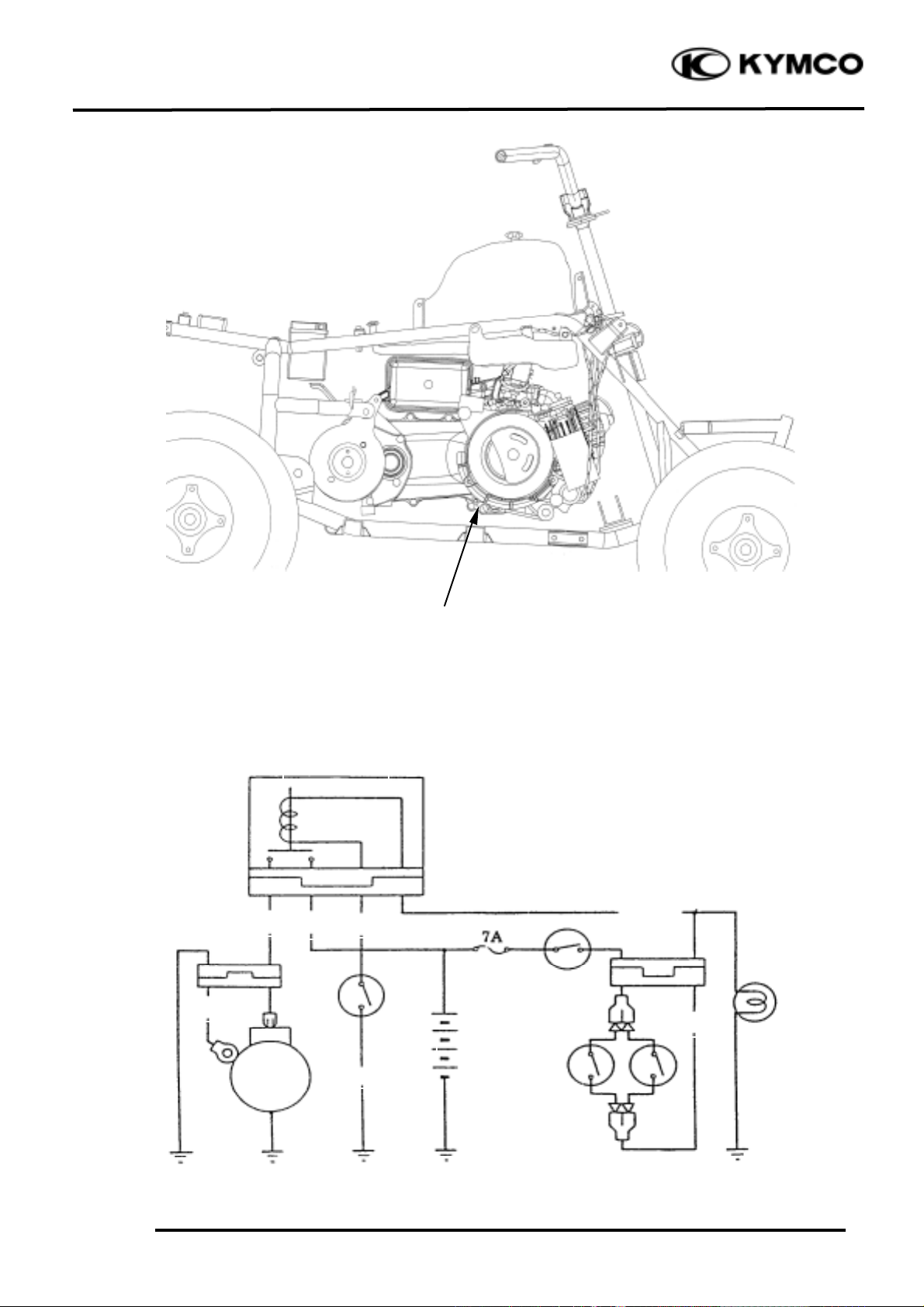
STARTING CIRCUIT
Starter Motor
G
G/Y
Ignition Switch
Fuse
Stop Switches
R
Y/R
Battery
Starter
Motor
Starter Relay
Rear
G
R/W
Front
G/Y
Stoplight
Start
Switch
Page 3

16. STARTING SYSTEM
16-2
Mongoose/KXR 90/50
SERVICE INFORMATION
GENERAL INSTRUCTIONS
• The removal of starter motor can be accomplished with the engine installed.
TROUBLESHOOTING
Starter motor won‘t turn Lack of power
• Fuse burned out • Weak battery
• Weak battery • Loose wire or connection
• Faulty ignition switch • Foreign matter stuck in starter motor
• Faulty starter clutch
or gear
• Faulty front or rear stop switch
• Faulty starter relay Starter motor rotates but engine does
• Poorly connected, broken or shorted wire
not start
• Faulty starter motor • Faulty starter clutch
• Faulty change gear control unit • Starter motor rotates reversely
• Weak battery
Page 4

16. STARTING SYSTEM
16-3
Mongoose/KXR 90/50
STARTER MOTOR
REMOVAL
Disconnect the starter motor cable.
Remove two mounting bolts at the starter
motor attaching left crankcase, then remove
the starter motor. (Mongoose/KXR 90’s
starter motor is located on the engine.
Mongoose/KXR 50’s starter motor is
located under the engine.)
DISASSEMBLY
Remove the two starter motor case screws,
front cover, motor case and other parts.
INSPECTION
Inspect the removed parts for wear, damage
or discoloration and replace if necessary.
Clean the commutator if there is metal
powder between the segments.
Check for continuity between pairs of the
commutator segments and there should be
continuity.
Also, make a continuity check between
individual commutator segments and the
armature shaft. There should be no
continuity.
Bolts
Before removing the starter motor, turn
the ignition switch OFF and remove the
battery ground. Then, turn on the
ignition switch and push the starter
button to see if the starter motor
operates properly.
°Ø
Front Cover
Commutator
Motor Case
Case Screws
Starter Motor
Page 5

16. STARTING SYSTEM
16-4
Mongoose/KXR 90/50
STARTER MOTOR CASE
CONTINUITY CHECK
Check to confirm that there is no continuity
between the starter motor wire terminal and
the motor front cover.
Also check for the continuity between the
wire terminal and each brush.
Replace if necessary.
Measure the length of the brushes.
Service Limit: 8.5mm replace if below
Check for continuity between the brushes.
If there is continuity, replace with new
ones.
Check if the needle bearing in the front cover
turns freely and has no excessive play.
Replace if necessary.
Check the dust seal for wear or damage.
Wire Terminal
Bearing
Dust Seal
Page 6

16. STARTING SYSTEM
16-5
Mongoose/KXR 90/50
ASSEMBLY
Apply grease to the dust seal in the front
cover.
Install the brushes onto the brush holders.
Apply a thin coat of grease to the two ends
of the armature shaft.
Insert the commutator into the front cover.
Install a new O-ring to the front cover.
Install the starter motor case, aligning the
tab on the motor case with the groove on the
front cover.
Tighten the starter motor case screws.
STARTER MOTOR INSTALLATION
Connect the starter motor cable connector
Check the O-ring for wear or damage and
replace it if necessary.
Apply grease to the O-ring and install the
starter motor.
Tighten the two mounting bolts.
Torque: 0.8_ 1.2kgf-m
• Be careful not to damage the brush and
armature shaft mating surfaces.
• When installing the commutator, the
armature shaft should not damage the
dust seal lip.
°Ø
When assembling the front cover and
motor case, slightly press down the
armature shaft to assemble them.
°Ø
Front Cover
Commutator
Motor Case
Grease
O-ring
O-ring
The starter motor cable connector must
be installed properly.
°Ø
Page 7

16. STARTING SYSTEM
16-6
Mongoose/KXR 90/50
STARTER RELAY
INSPECTION
Remove the seat. (Refer to the chapter 2)
Turn the ignition switch ON and the starter
relay is normal if you hear a click when the
starter button is depressed.
If there is no click sound:
• Inspect the starter relay voltage
• Inspect the starter relay ground circuit
• Check for continuity between the starter
relay yellow/red and green/red wire
terminals
STARTER RELAY VOLTAGE
INSPECTION
Connect a 12V battery across the starter
relay yellow/red and green/red wire
terminals.
Connect an electric tester between the
starter relay large terminals and check for
continuity between the two terminals.
The relay is normal if there is continuity.
Replace the starter relay with a new one if
there is no continuity.
Starter Relay
Starter Relay (Mongoose/KXR 90)
Starter Relay (Mongoose/KXR 50)
Page 8

16. STARTING SYSTEM
16-7
Mongoose/KXR 90/50
STARTER PINION
(Mongoose/KXR 90)
REMOVAL
Remove the left crankcase cover and drive
pulley face. (Refer to chapter 9)
Remove the starter one-way clutch drive
nut.
Lock nut socket wrench E015
Remove starter one-way clutch drive.
Start clutch puller E006
Remove the reduction gear case.
Remove the reduction gear.
INSTALLATION
Install each washer to the top and bottom of
the reduction gear.
Apply grease to the reduction gear shaft
forcing part.
Then, install in the reverse order of removal.
STARTER ONE-WAY CLUTCH
DISASSEMBLY
Remove the 32mm lock nut with special
tool.
Take the starter one-way clutch drive gear
off.
Lock nut socket wrench E015
Reduction Gear Case
Starter One-way Clutch Drive Nut
Starter Gear Shaft
Reduction Gear
Washers
Reduction Gear Case
Starter Oneway Clutch Drive Gear
32mm Lock Nut
Special
Special
Special
Page 9

16. STARTING SYSTEM
16-8
Mongoose/KXR 90/50
INSPECTION
Inspect the starter one-way clutch drive gear
teeth for burrs/chips/roughness/wear.
Inspect the starter one-way clutch drive gear
contacting surfaces for pitting/wear/damage.
Push the weight roller to arrow direction for
unsmooth operation. _ Replace starter
clutch assembly.
ASSEMBLY
Install the starter one-way clutch driver gear in
the reverse order of removal.
s Torque: 5.0_ 6.0kgf-m
Check starter clutch operation.
Clutch operation checking steps:
s Install the starter wheel gear to the starter
clutch, and hold the starter clutch.
s When turning the wheel gear clockwise (1)
the starter clutch and the wheel gear should
be engaged. If not, the starter clutch is
faulty. Replace it.
s When turning the wheel gear
counterclockwise (2), the wheel gear
should turn freely. If not, the starter clutch
is faulty. Replace it.
Starter Oneway Clutch
Drive Gear
Starter Oneway Clutch
32mm Lock Nut
Starter Clutch Bolts
Contacting Surfaces
Teeth
Do not reuse the starter clutch bolts that
have been removed.
*
Page 10

16. STARTING SYSTEM
16-9
Mongoose/KXR 90/50
STARTER PINION
(Mongoose/KXR 50
REMOVAL
Remove the left crankcase cover.
Remove the drive pulley.
(Refer to chapter 9)
Remove the starter pinion cover.
Remove the starter pinion.
INSPECTION
Inspect the starter pinion seat for wear.
Inspect the starter pinion for smooth
operation.
Inspect the starter pinion shaft forcing parts
for wear and damage.
INSTALLATION
Apply a small amount of grease to the
starter pinion teeth.
Install the starter pinion in the reverse order
of removal.
Starter Pinion
Shaft Forcing Parts
Starter Pinion
Starter Pinion Cover
 Loading...