

Page 1

3. INSPECTION/ADJUSTMENT
3-0
Mongoose/KXR 90/50
3
__________________________________________________________________________________
__________________________________________________________________________________
__________________________________________________________________________________
__________________________________________________________________________________
__________________________________________________________________________________
INSPECTION/ADJUSTMENT
__________________________________________________________________________________
SERVICE INFORMATION -------------------------------------------- 3- 1
MAINTENANCE SCHEDULE ---------------------------------------- 3- 3
FUEL LINE/THROTTLE OPERATION------------------------------ 3- 4
AIR CLEANER ---------------------------------------------------------- 3- 5
SPARK PLUG/CYLINDER COMPRESSION ------------------------ 3- 7
VALVE CLEARANCE (Mongoose/KXR 90)------------------------- 3- 8
CARBURETOR IDLE SPEED ----------------------------------------- 3- 8
ENGINE OIL (Mongoose/KXR 90)------------------------------------ 3- 9
TRANSMISSION OIL -------------------------------------------------- 3-11
DRIVE BELT/BRAKE SHOES/BRAKE PADS/BRAKE FLUID -- 3-12
BRAKE LEVER FREE PLAY ----------------------------------------- 3-13
STEERING SYSTEM INSPECTION --------------------------------- 3-14
TOE-IN ADJUSTMENT------------------------------------------------ 3-15
WHEELS/TIRES -------------------------------------------------------- 3-16
DRIVE CHAIN SLACK ADJUSTMENT ----------------------------- 3-17
CABLE INSPECTION AND LUBRICATION ----------------------- 3-19
FRONT SUSPENSION LUBRICATION------------------------------ 3-19
HEADLIGHT BEAM ADJUSTMENT (ON ROAD ONLY) -------- 3-20
BRAKE PEDAL ADJUSTMENT (KXR 90 ON ROAD ONLY)---- 3-20
BRAKE FULID (KXR 90 ON ROAD ONLY)------------------------ 3-21
3
Page 2
3. INSPECTION/ADJUSTMENT
3-1
Mongoose/KXR 90/50
SERVICE INFORMATION
GENERAL
°I WARNING
•Before running the engine, make sure that the working area is well-ventilated. Never run the
engine in a closed area. The exhaust contains poisonous carbon monoxide gas which may cause
death to people.
•Gasoline is extremely flammable and is explosive under some conditions. The working area
must be well-ventilated and do not smoke or allow flames or sparks near the working area or
fuel storage area.
SPECIFICATIONS (Mongoose/KXR 90)
ENGINE
Throttle grip free play : 1_ 4mm
Spark plug gap : 0.6_ 0.7mm
Spark plug: Standard : NGK: C7HSA
Valve clearance : IN: 0.1m
EX: 0.1m
Idle speed : 1700±100rpm
Engine oil capacity:
At disassembly : 0.8 liter
At change : 0.7 liter
Gear oil capacity :
At disassembly : 120cc
At change : 110cc
Cylinder compression : 16kg/cm_
Ignition timing : BTDC 28°/4000rpm
CHASSIS
Front brake free play: 10_ 20mm
Rear brake free play: 10_ 20mm
TIRE PRESSURE
1 Rider
Front
0.22kgf/cm_
Rear
0.22kgf/cm_
TIRE SIZE:
Front : 18*7-8
Rear : 18*9-8
TORQUE VALUES
Front wheel nut 4.0_ 5.0kgf-m
Rear wheel nut 4.0_ 5.0kgf-m
Page 3
3. INSPECTION/ADJUSTMENT
3-2
Mongoose/KXR 90/50
SPECIFICATIONS (Mongoose/KXR 50)
ENGINE
Throttle grip free play : 1_ 4mm
Spark plug gap : 0.6_ 0.7mm
Spark plug: Standard : NGK: BR8HAS
Idle speed : 2000±100rpm
Gear oil capacity :
At disassembly : 120cc
At change : 110cc
Cylinder compression : 12kg/cm_
Ignition timing : BTDC 15°/1700rpm
CHASSIS
Front brake free play: 10_ 20mm
Rear brake free play: 10_ 20mm
TIRE PRESSURE
1 Rider
Front
0.22kgf/cm_
Rear
0.22kgf/cm_
TIRE SIZE:
Front : 16*8-7
Rear : 16*8-7
TORQUE VALUES
Front wheel nut 4.0_ 5.0kgf-m
Rear wheel nut 4.0_ 5.0kgf-m
Page 4
3. INSPECTION/ADJUSTMENT
3-3
Mongoose/KXR 90/50
MAINTENANCE SCHEDULE
This chapter includes all information necessary to perform recommended inspections and
adjustments. These preventive maintenance procedures, if followed, will ensure more reliable
vehicle operation and a longer service life. The need for costly overhaul work will be greatly
reduced. This information applies to vehicles already in service ad well as new vehicles that are
being prepared for sale. All service technicians should be familiar with this entire chapter.
Initial
Every
Item
Remarks
1
month
3
month
6
month
6
month
1
year
Valves
(Mongoose/KXR 50)
Check valve clearance. Adjust if
necessary.
°≥°≥°≥
°≥
Spark plug
Check condition. Clean or replace if
necessary.
°≥°≥°≥°≥°≥
Air clearance
Clean. Replace if necessary.
°≥°≥°≥
°≥
Carburetor
Check idle speed/starter operation.
Adjust if necessary.
°≥°≥°≥
°≥
Fuel line
Check fuel hose for cracks or
damage. Replace if necessary.
°≥°≥°≥
Engine oil
(Mongoose/KXR 50)
Replace (Warm engine before
draining).
°≥°≥°≥
°≥
Engine oil filter
screen
(Mongoose/KXR 50)
Clean. Replace if necessary.
°≥
°≥
Transmission oil
Check oil leakage. Replace every 12
months.
°≥
°≥
Brake system
Check operation. Adjust if
necessary.
°≥°≥°≥°≥°≥
Drive belt
Check operation/replace if damage
or excessive wear.
°≥
°≥
Wheels
Check balance/damage/runout.
Replace if necessary.
°≥°≥°≥
°≥
Wheel bearings
Check bearings assembly for
looseness/damage. Replace if
damaged.
°≥°≥°≥
°≥
Steering system
Check operation/replace if damage.
Check toe-in/adjust if necessary.
°≥°≥°≥°≥°≥
Knuckle shafts
Lubricate every 6 months.
°≥°≥°≥
Fitting/Fasteners
Check all chassis fittings and
fasteners. Correct if necessary.
°≥°≥°≥°≥°≥
• In the interest of safety, we recommend these items should be serviced only by an
authorized KYMCO motorcycle dealer.
Page 5
3. INSPECTION/ADJUSTMENT
3-4
Mongoose/KXR 90/50
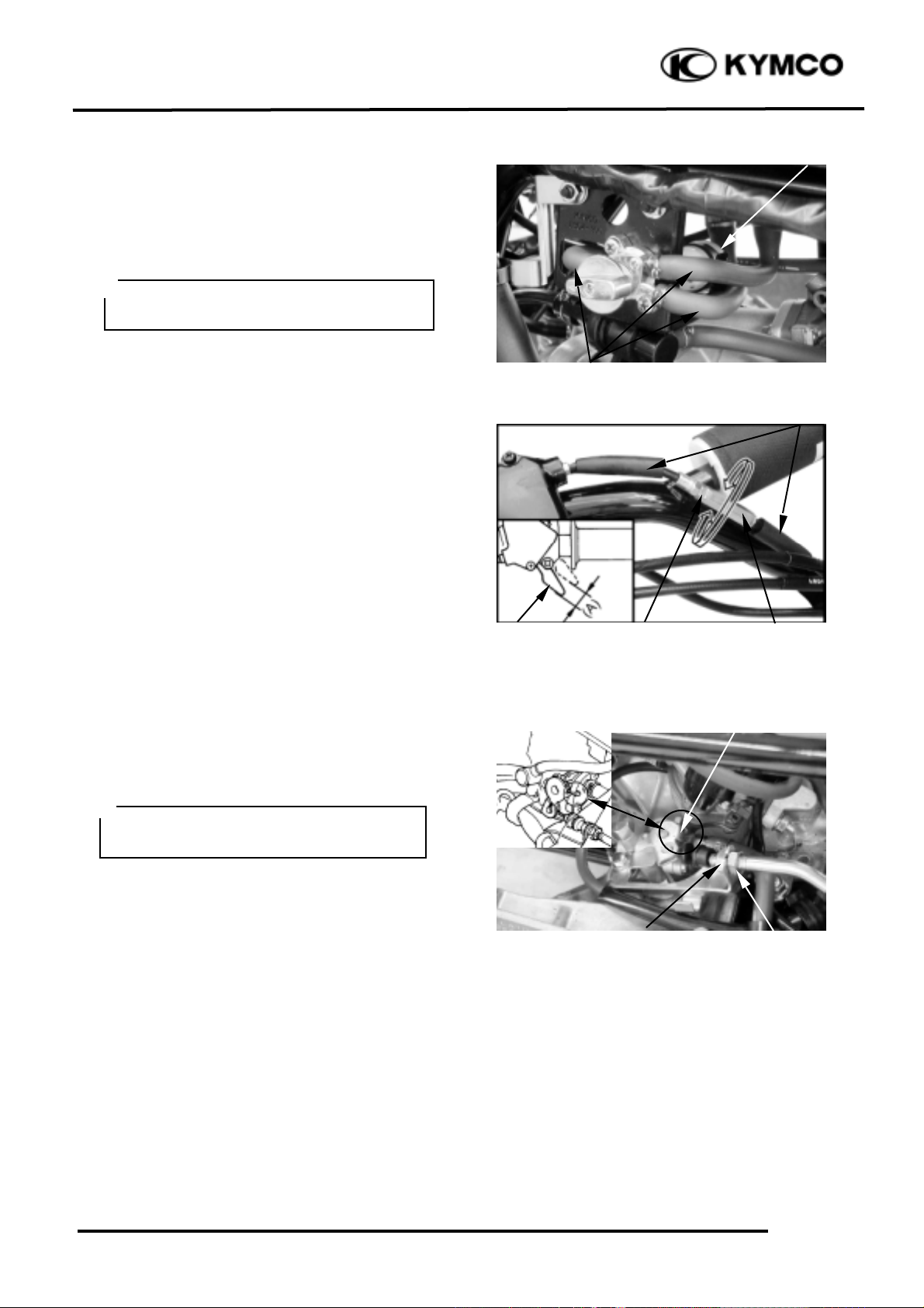
FUEL LINE
Check the fuel tubes and replace any parts,
which show signs of deterioration, damage
or leakage.
THROTTLE OPERATION
Check the throttle to swing for smooth
movement.
Measure the throttle to swing free play.
Free Play: 1_ 4mm
To adjust throttle free play:
1. Slide the rubber sleeves back to expose
the throttle cable adjuster.
2. Loosen the lock nut, then turn the
adjuster to obtain the correct free play.
(1~4 mm or 0.04~0.16 in)
3. Tighten the lock nut and reinstall the
sleeve.
OIL PUMP ADJUSTMENT
(Mongoose/KXR 50)
Open the throttle valve fully and check that
the index mark on the pump body aligns
with the aligning mark on the oil pump
control lever.
Reference tip alignment within 1mm of
index mark on open side is acceptable.
Start and idle the engine, then slowly open
the throttle to increase engine rpm and check
the operation of the oil pump control lever.
If adjustment is necessary, adjust the oil
pump control cable by loosening the control
cable lock nut and turning the adjusting nut.
After adjustment, tighten the lock nut.
Fuel Filter
Fuel Tubes
Rubber Sleeves
Lock Nut
Cable Adjuster
Throttle Lever
Adjust oil pump control cable after the
throttle grip free play is adjusted.
°Ø
Control Lever Aligning Mark
Lock Nut
Adjusting Nut
Do not smoke or allow flames or sparks
in your working area.
°Ø
Page 6
3. INSPECTION/ADJUSTMENT
3-5
Mongoose/KXR 90/50
If the oil pump is not synchronized
properly, the following will occur:
• Excessive white smoke or hard starting due
to pump control lever excessively open
• Seized piston due to pump control lever
insufficiently open
AIR CLEANER
AIR CLEANER
REPLACEMENT/CLEANING
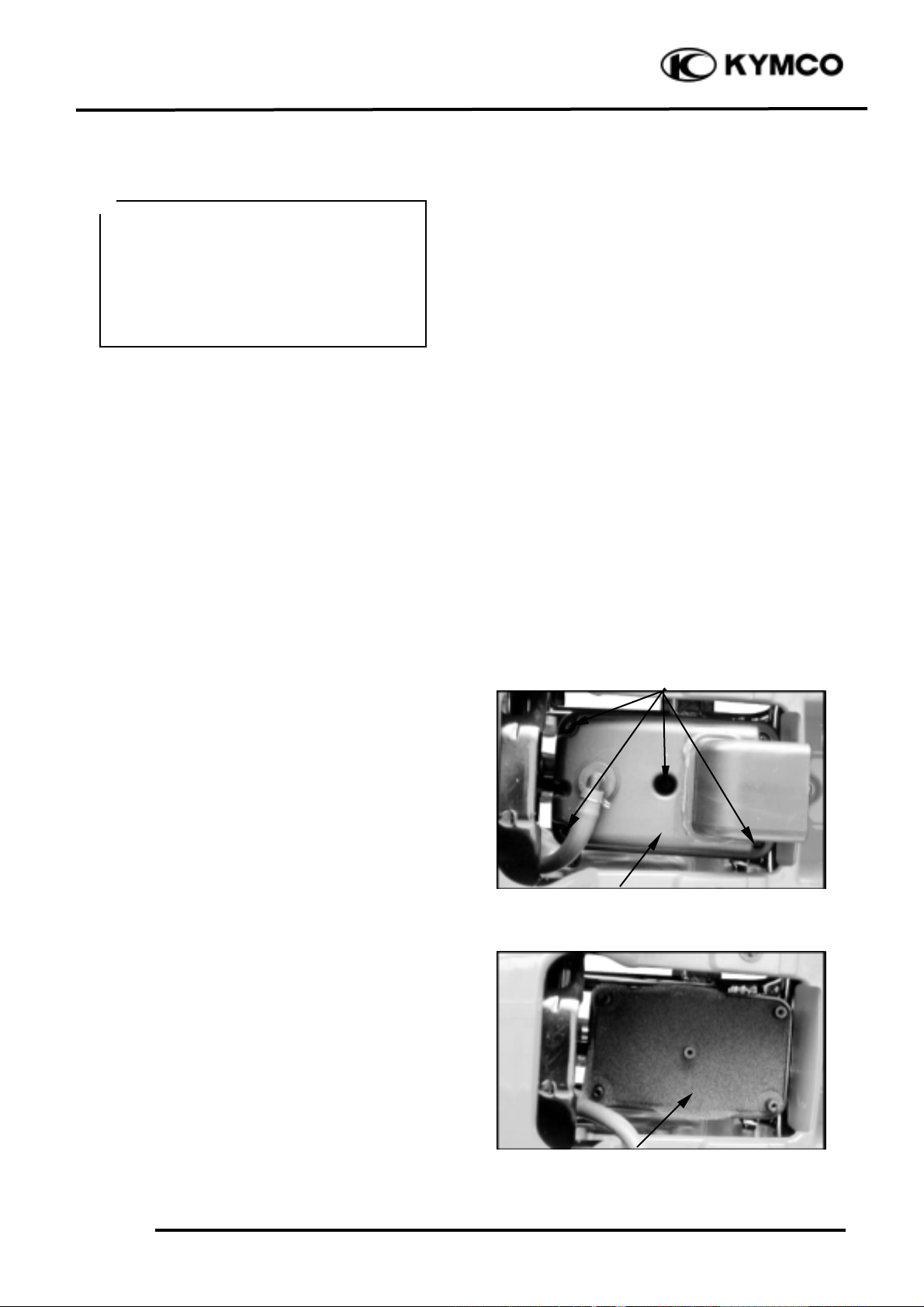
To replace the air cleaner
(Mongoose/KXR 90):
1. Remove the seat. (See page 2-3.)
2. Remove the five screws and then remove
air filter case cover.
3. Remove the air filter element, and
separate it from the box.
Screws
Air Filter Case Cover
Air Filter Element
Reference tip alignment within 1mm of
index mark on open side is acceptable.
However, the aligning mark on the
control lever must never be on the closed
side of the index mark, otherwise engine
damage will occur because of insufficient
lubrication.
°Ø
Page 7
3. INSPECTION/ADJUSTMENT
3-6
Mongoose/KXR 90/50
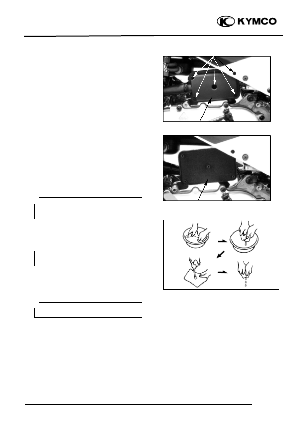
To replace the air cleaner
(Mongoose/KXR 50):
1. Remove the five screws and air filter case
cover.
2. Remove the air filter element, and
separate it from the box.
To clean the air filter element:
1. Wash the element gently but thoroughly
in solvent.
2. Squeeze the excess solvent out of the
filter and let it dry.
3. Inspect the element. If damaged, replace
it.
4. Apply quality foam air filter oil to the
element. If foam air filter oil is not
available, motor oil may be used.
5. Reinstall the element to the air filter case.
6. Reinstall the element assembly and parts
removed for access.
Apply the engine oil.
Squeeze out the excess oil.
CHANGE INTERVAL
More frequent replacement is required when
riding in unusually dusty or rainy areas.
Use parts cleaning solvent only. Never
use gasoline or low flash point solvents
which may lead to a fire or explosion.
°Ø
Do not twist or wring out the foam
element. This could damage the foam
material.
°Ø
The element should be wet but not
dripping.
°Ø
Air Filter Element
Screws
Air Filter Case Cover
Page 8

3. INSPECTION/ADJUSTMENT
3-7
Mongoose/KXR 90/50
Gap, Wear, and Fouling Deposits
SPARK PLUG
Remove the ignition coil cap and spark plug.
Check the spark plug for wear and fouling
deposits.
Clean any fouling deposits with a spark
plug cleaner or a wire brush.
Specified Spark Plug:
(Mongoose/KXR 90): NGK: C7HSA
(Mongoose/KXR 50): NGK: BR8HAS
Measure the spark plug gap.
Spark Plug Gap: 0.6_ 0.7mm
CYLINDER COMPRESSION
Warm up the engine before compression
test.
Remove the spark plug.
Insert a compression gauge.
Open the throttle valve fully and push the
starter button to test the compression.
Compression:
(Mongoose/KXR 90): 16kg/cm_
(Mongoose/KXR 50): 12kg/cm_
If the compression is low, check for the
following:
- Leaky valves
- Valve clearance too small
- Leaking cylinder head gasket
- Worn piston rings
- Worn piston/cylinder
If the compression is high, it indicates that
carbon deposits have accumulated on the
combustion chamber and the piston head.
Cracks, Damage
Washer Deformation
Ignition Coil Cap/Spark Plug
When installing, first screw in the spark
plug by hand and then tighten it with a
spark plug wrench.
°Ø
Compression Gauge
Page 9

3. INSPECTION/ADJUSTMENT
3-8
Mongoose/KXR 90/50
VALVE CLEARANCE
(Mongoose/KXR 90):
Disconnect the oil recycle tube at the
cylinder head cover.
Remove the four bolts and cylinder head
cover.
Remove the two screws and two bolts, then
remove the fan cover.
Turn the cooling fan clockwise so that the
“T” mark on the flywheel aligns with the
index mark on the crankcase to bring the
round hole on the camshaft gear facing up to
the top dead center on the compression
stroke.
Inspect and adjust the valve clearance.
Valve Clearance: IN: 0.1mm
EX: 0.1mm
Loosen the lock nut and adjust by turning
the adjusting nut
Tappet adjuster E012
CARBURETOR IDLE SPEED
Warm up the engine before this operation.
Start the engine and connect a tachometer.
Turn the throttle stop screw to obtain the
specified idle speed.
Idle Speed:
(Mongoose/KXR 90): 1700±100rpm
(Mongoose/KXR 50): 2000±100rpm
When the engine misses or run erratic, adjust
the air screw.
Inspect and adjust valve clearance while
the engine is cold (below 35¢J).
°Ø
• Check the valve clearance again after
the lock nut is tightened.
°Ø
Cylinder Head Cover
Special
Bolts
Cooling Fan Cover
Screws
Bolts
Round Hole
Punch Marks
Tappet Adjuster
Throttle Stop Screw
Air Screw
• The engine must be warm for accurate
idle speed inspection and adjustment.
°Ø
Page 10

3. INSPECTION/ADJUSTMENT
3-9
Mongoose/KXR 90/50
ENGINE OIL (Mongoose/KXR 90)
OIL LEVEL
Remove the two bolts and right side cover.
Place the machine on a level place.
Warm up the engine for several minutes and
stop it.
Remove the dipstick and wipe it off with a
clean rag. Insert the dipstick in the filler hole
without screwing it in.
Remove the dipstick and inspect the oil
level.
The oil level should be between the
maximum and minimum marks. If the level is
low, add oil to raise it to the proper level.
ENGINE OIL REPLACEMENT
Place the machine on a level place.
Warm up the engine for several minutes and
stop it.
Place a container under the engine.
Remove right side cover.
Remove the oil filler cap and drain plug to
drain the oil.
Reinstall the drain plug and tighten the drain
plug to specification.
Torque: 2.0_ 3.0kgf-m
Fill the engine with oil and install the oil
filler cap.
Warm up the engine for several minutes at
idle speed. Check for oil leakage while
warming up.
Oil Capacity: At disassembly: 0.8L
At change: 0.7L
Maximum Level Mark
Dipstick/Oil Filler Cap
Minimum Level Mark
Dipstick/Oil Filler Cap
Drain Plug
Be sure no foreign material enters the
crankcase.
°Ø
Run the engine for 2_ 3 minutes and
check the oil level after the engine is
stopped for 2_ 3 minutes.
°Ø
Right Side Cover
Bolts
Page 11

3. INSPECTION/ADJUSTMENT
3-10
Mongoose/KXR 90/50
ENGINE OIL REPLACEMENT AND OIL
FILTER CLEANING
A. Place the machine on a level place.
B. Warm up the engine for several minutes
and stop it.
C. Place a container under the engine.
D. Remove the oil filler cap and oil filter cap
to drain the oil.
E. Clean the oil strainer with solvent.
F. Inspect the O-ring and replace if
damaged.
G. Reinstall the O-ring, oil strainer,
compression spring and drain plug.
Tighten the drain plug to specification.
Torque: 1.0_ 2.0kgf-m
Oil Capacity: At disassembly: 0.8L
At change: 0.7L
Oil Filter Cap
°DBe sure no foreign material enters the
crankcase.
°DWhen removing the drain plug, the
compression spring, oil strainer and
O-ring will fall out. Take care not to
lose these parts.
°Ø
Before reinstalling the drain plug, be sure
to install the O-ring, compression spring
and oil strainer.
°Ø
Oil Filter Cap
Compression Spring
Oil Strainer
O-ring
Page 12

3. INSPECTION/ADJUSTMENT
3-11
Mongoose/KXR 90/50
TRANSMISSION OIL
TRANSMISSION OIL MEASUREMENT
Place the machine on a level place.
Remove the oil filler bolt and check the oil
level. It should be up to the brim of the hole.
If the level is low, add oil to raise it to the
proper level.
Reinstall the oil filler bolt and tighten to
specification.
Torque: 1.0_ 2.0kgf-m
TRANSMISSION OIL REPLACEMENT
Place the machine on a level place.
Place a container under the engine.
Remove the oil filler bolt and drain plug to
drain the oil.
Reinstall the drain plug and tighten to
specification.
Torque: 1.0_ 2.0kgf-m
Fill the engine with oil and install the oil
filler bolt.
Torque: 1.0_ 2.0kgf-m
Oil Capacity: At disassembly: 0.12L
At change: 0.11L
Start the engine and warm up for a few
minutes. While warming up, check for oil
leakage. If oil leakage is found, stop the
engine immediately and check for the cause.
Oil Filter Bolt/Measurement Hole
Drain Plug
Be sure no foreign material enters the
crankcase.
°Ø
Page 13

3. INSPECTION/ADJUSTMENT
3-12
Mongoose/KXR 90/50
DRIVE BELT
Remove the left crankcase cover.
Inspect the drive belt for cracks, scaling,
chipping or excessive wear.
Measure the V-belt width
Service limit:
Mongoose/KXR 90:16.5mm
Mongoose/KXR 50:16.5mm
Replace the drive belt if out of specification.
BRAK SHOES
The checking of brake shoes wear will
disassemble the brake. If the lining thickness
below to the wear limit (A) 2.0mm (0.08in),
to replace the shoes as a set.
BRAKE PADS
A wear indicator is provided on each brake.
The indicators allows checking of brake
pads wear. Check the position of the
indicator. If the indicator reaches the wear
limit line, to replace the pads.
BRAKE FLUID
Check if the fluid level is below the lower
level mark through the inspection window.
Drive Belt
Inspection Window
Page 14

3. INSPECTION/ADJUSTMENT
3-13
Mongoose/KXR 90/50
BRAKEN LEVER FREE PLAY
(DRUM BRAKE)
The brake lever free play (A) should be
adjusted to 10~20 mm (0.4~0.8 in) at the tip
of the brake lever.
FRONT BRAKE FREE PLAY
ADJUSTMENT
Loosen the upper lock nut and fully turn in
the adjusting bolt.
Loosen the lower lock nut.
Turn the lower adjusting bolt until specified
free play is obtained.
Tighten the lower lock nut.
While applying the front brake, turn out the
upper adjusting bolt until the upper and
lower cable lengths (A) are equal. The cable
joint will become vertical.
Tighten the upper lock nut.
REAR BRAKE FREE PLAY
ADJUSTMENT
Turn the adjusting nut on the brake hub in
direction A to decrease play, and in
direction B to increase play.
Lock Nuts
Adjusting Bolts
Page 15

3. INSPECTION/ADJUSTMENT
3-14
Mongoose/KXR 90/50
STEERING SYSTEM
INSPECTION
Place the machine on a level place.
Check the steering column bushings and
bearings:
Move the handlebar up and down, and/or
back and forth.
Replace the steering column bushings and or
bearings if excessive play
Check the tie-rod ends
Turn the handlebar to the left and/or right
until it stops completely, then slightly move
the handlebar from left to right.
Replace the tie-rod ends if tie-rod end has
any vertical play.
Raise the front end of the machine so that
there is no weight on the front wheels.
Check ball joints and/or wheel bearings.
Move the wheels lately back and froth.
Replace the front arms and/or wheel
bearings if excessive free play.
Tie-rod Ends
Make sure the cut-out on the adjusting
nut Is seated on the brake arm pin after
making final free play adjustment.
°Ø
Arm Pin
Adjusting Nut
Page 16

3. INSPECTION/ADJUSTMENT
3-15
Mongoose/KXR 90/50
TOE-IN ADJUSTMENT
Place the machine on a level place.
Measure the toe-in
Adjust if out of specification.
Toe-in measurement steps:
Mark both front tire tread centers.
Raise the front end of the machine so that
there is no weight on the front tires.
Fix the handlebar straight ahead.
Measure the width A between the marks.
Rotate the front tires 180 degrees until the
marks come exactly opposite.
Measure the width B between the marks.
Calculate the toe-in using the formula given
below.
Toe-in = B°– A
Toe-in: 0_ 15mm
If the toe-in is incorrect, adjust the toe-in
Adjust the toe-in step:
Mark both tie-rods ends.
This reference point will be needed during
adjustment.
Loosen the lock nuts (tie-rod end) of both
tie-rods
The same number of turns should be given
to both tie-rods right and left until the
specified toe-in is obtained, so that the
lengths of the rods will be kept the same.
Torque: 2.5_ 3.5kgf-m
• Be sure that both tie-rod are
turned the same amount. If not, the
machine will drift tight or left even
though the handlebar is positioned
straight which may lead to mishandling
and accident.
• After setting the toe-in to
specification, run the machine slowly
for some distance with hands placed
lightly on the handlebar and check that
the handlebar responds correctly. If
not, turn either the right or left tie-rod
within the toe-in specification.
°Ø
A
B
Tie-rod
Tie-rod End Nuts
Tie-rod
Tie-rod End Nuts
Page 17

3. INSPECTION/ADJUSTMENT
3-16
Mongoose/KXR 90/50
WHEELS/TIRES
Check the tires for cuts, imbedded nails or
other damages.
Check the tire pressure.
TIRE PRESSURE
1 Rider
Front
0.22kgf/cm_
Rear
0.22kgf/cm_
TIRE SIZE (Mongoose/KXR 90)
Front : 18*7-8
Rear : 18*9-8
TIRE SIZE (Mongoose/KXR 50)
Front : 16*8-7
Rear : 16*8-7
Check the front wheel hub nut for
looseness.
Check the rear wheel hub nut for looseness.
If the axle nuts are loose, tighten them to the
specified torque.
Torque: Front : 5.5_ 6.5kgf-m
Rear : 6.0_ 8.0kgf-m
WHEEL INSPECTION
Inspect the tire surfaces.
Replace if wear or damage.
Tire wear limit: 3.0mm
Front Axle Nut
Tire pressure should be checked when
tires are cold.
°Ø
Rear Axle Nut
It is dangerous to ride with a worn out
tire. When a tire wear is out of
specification, replace the tire
immediately.
°Ø
Page 18

3. INSPECTION/ADJUSTMENT
3-17
Mongoose/KXR 90/50
Inspect the wheel.
Replace if damage or bends
Always balance the wheel when a tire or
wheel has been changed or replaced.
DRIVE CHAIN SLACK
ADJUSTMENT
Before checking and/or adjusting, rotate the
rear wheels several revolutions and check
slack at several points to find the tightest
point. Check and/or adjust the chain slack
with the rear wheels in this “tightest”
position.
Place the machine on a level place.
Check drive chain slack (A).
Adjust if out of specification.
Drive chain slack: Approximately
10~20mm
Adjust drive chain slack:
Elevate the rear wheels by placing a suitable
stand under the rear of frame.
Loosen the upper and lower axle holding
bolts.
Bolts
• Never attempt even small repairs
to the wheel.
• Ride conservatively after
installing a tire to allow it to seat itself
properly on the rim.
°Ø
Too little of chain slack will overload the
engine and other vital parts; keep the
slack within the specified limits.
°Ø
Wheels should be on the ground without
the rider on it.
°Ø
Support the machine securely so there is
no danger of it falling over.
°Ø
Hub Stopper Nut
Page 19

3. INSPECTION/ADJUSTMENT
3-18
Mongoose/KXR 90/50
Turn the adjusting nut, to decrease or
increase chain slack.
Retighten the upper and lower axle holding
bolts.
Torque: 6.0_ 8.0kgf-m
Drive chain cleaning and lubrication
The drive chain is equipped with rubber O-
rings between the chain plates. Steam
cleaning, high-pressure washes, and certain
solvents can damage these O-rings. Use only
kerosene to clean the drive chain. Wipe it
dry, and thoroughly lubricate it with SAE
30~50 motor oil. Do not use any other
lubricants on the drive chain. They may
contain solvents that could damage the O-
rings.
Adjusting Nut
O-ring
Page 20

3. INSPECTION/ADJUSTMENT
3-19
Mongoose/KXR 90/50
CABLE INSPECTION AND
LUBRICATION
Inspect the cable sheath.
Replace if damage.
Check the cable operation.
Lubricate or replace if unsmooth operation.
LEVER LUBRICATION
Lubricate the pivoting parts of each lever.
SUSPENSION LUBRICATION
Inject grease into the nipples using a grease
gun until slight over flow is observed from
the thrust covers.
Front Swing
Arm Nipple
Damaged cable sheath may cause
corrosion and interfere with the cable
movement. An unsafe condition may
result so replace such cable as soon as
possible.
°Ø
Wipe off the excess grease.
°Ø
Hold cable end high and apply several
drops of lubricant to cable.
°Ø
Rear Swing
Arm Nipple
Page 21

3. INSPECTION/ADJUSTMENT
3-20
Mongoose/KXR 90/50
HEADLIGHT BEAM
ADJUSTMENT (ON ROAD
ONLY)
Vertical adjustment:
Turn the ignition switch ON and start the
engine.
Turn on the headlight switch.
Adjust the headlight aim by turning the
headlight aim adjusting screw.
BRAKE PEDAL ADJUSTMENT
(KXR 90 ON ROAD ONLY)
The brake pedal free play should be
adjusted to 5~10 mm (0.2~0.4 in) at the
brake pedal pivot. If the free play is
incorrect, adjust as follows:
Adjust:
1. Keep front brake lever free play at 10~20
mm (0.4~0.8 in).
2. Loosen the locknuts. (R/L front lower
brake cables)
3. Turn the adjusting bolts until the front
lower brake cables is tensed.
4. Apply the front brake lever and check
front brake cam lever to make sure that
the brake does not drag after adjusting.
5. While remove the cable joint case cover
and applying the brake pedal, make sure
the left and right front lower cable lengths
(A and B) are equal. The cable joint will
become vertical.
6. Tighten the locknuts. (R/L front lower
brake cables)
Headlight
Adjusting screw
Adjusting Bolts
Locknuts
Brake Cam Lever
R/L Front Lower Cable
Cable Joint Case Cover
Bolts
Cable Joint
Page 22

3. INSPECTION/ADJUSTMENT
3-21
Mongoose/KXR 90/50
7. Loosen the locknut. (Brake pedal cable)
8. Turn the adjusting bolt until the specified
free play is obtained.
9. Tighten the locknut. (Brake pedal cable)
BRAKE FLUID (KXR 90 ON
ROAD ONLY)
Check if the fluid level is below the lower
level mark through the inspection window.
Locknut
Adjusting Blot
Brake Pedal Cable
 Loading...