

Page 1

11.CRANKSCASE/CRANKSHAFT
11-0
Mongoose/KXR 90/50
11
__________________________________________________________________________________
__________________________________________________________________________________
__________________________________________________________________________________
__________________________________________________________________________________
__________________________________________________________________________________
CRANKCASE/CRANKSHAFT
__________________________________________________________________________________
SERVICE INFORMATION -------------------------------------------- 11- 3
CRANKCASE/CRANKSHAFT (Mongoose/KXR 90)---------------- 11- 4
CRANKCASE/CRANKSHAFT (Mongoose/KXR 50)---------------- 11- 7
11
Page 2
11.CRANKCASE/CRANKSHAFT
11-1
Mongoose/KXR 90/50
Mongoose/KXR 90
Page 3
11.CRANKSCASE/CRANKSHAFT
11-2
Mongoose/KXR 90/50
Mongoose/KXR 50
Page 4
11.CRANKCASE/CRANKSHAFT
11-3
Mongoose/KXR 90/50
SERVICE INFORMATION
GENERAL INSTRUCTIONS
• This section covers crankcase separation to service the crankshaft. The engine must be removed
for this operation.
• The following parts must be removed before separating the crankcase.
-Cylinder head (!Chapter 7 (Mongoose/KXR 90))
-Cylinder/piston (!Chapter 8)
-Drive and driven pulleys (!Chapter 9)
-A.C. generator (!Chapter 14)
-Starter clutch (!Chapter 16)
-Oil pump (!Chapter 4)
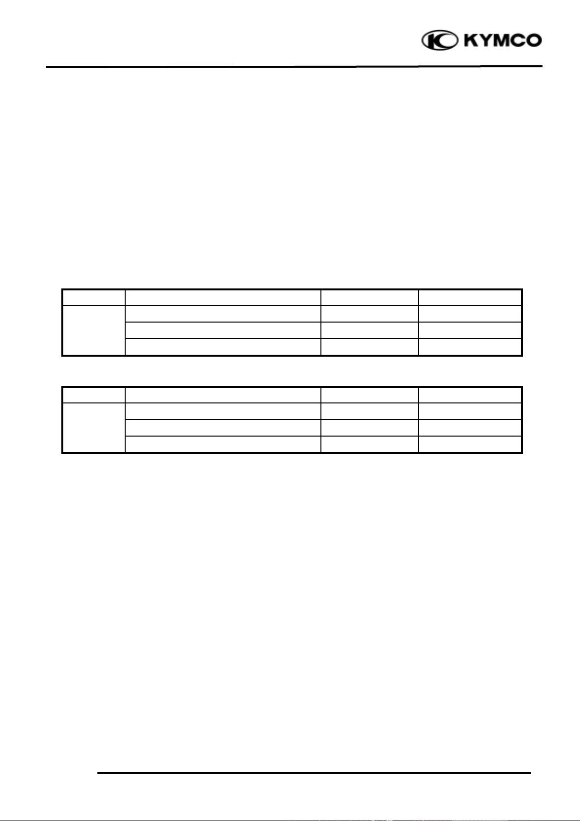
SPECIFICATIONS (Mongoose/KXR 90)
Item
Standard (mm)
Service Limit (mm)
Connecting rod small end free play
0.05_ 0.4
0.6
Crankshaft
Connecting rod big end radial clearance
0_ 0.008
0.05
Run outæ0.10
SPECIFICATIONS (Mongoose/KXR 50)
Item
Standard (mm)
Service Limit (mm)
Connecting rod big end side clearance
æ
0.6
Crankshaft
Connecting rod big end radial clearance
æ
0.04
Run out A/B
æ
0.1/0.15
TORQUE VALUES
Crankcase bolt 0.8_ 1.2kgf-m
Cam chain tensioner slipper bolt 0.8_ 1.2kgf-m (Mongoose/KXR 90)
SPECIAL TOOLS (Mongoose/KXR 50)
Crankcase puller E026
Universal bearing puller E030
Crankshaft install tool E016
Crankcase assembly tool E024
Oil seal and bearing install tool E014
TROUBLESHOOTING
Abnormal engine noise
• Excessive crank journal bearing play
• Excessive crankpin bearing play
• Excessive transmission bearing play
Page 5

11.CRANKSCASE/CRANKSHAFT
11-4
Mongoose/KXR 90/50
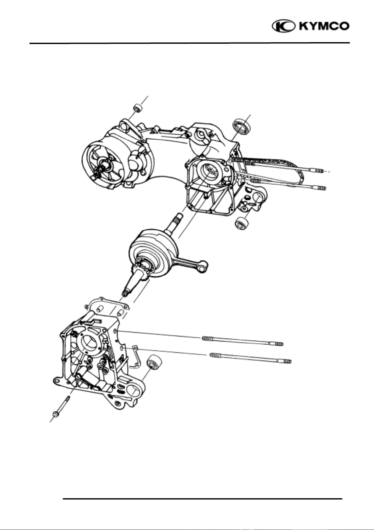
CRANKCASE/CRANKSHAFT
(Mongoose/KXR 90)
REMOVAL
Remove the crankcase attaching bolt.
Separate the left and right crankcase halves.
Remove the crankshaft from the left
crankcase.
Remove the cam chain.
Remove the gasket and dowel pins.
Clean off all gasket material from the
crankcase mating surfaces.
Bolt
Crankshaft
• Do not damage the crankcase
gasket surface.
• Never use a driver to pry the
crankcase mating surfaces apart.
*
Cam Chain
Dowel Pins
Gasket
Avoid damaging the crankcase mating
surfaces.
*
Page 6

11.CRANKCASE/CRANKSHAFT
11-5
Mongoose/KXR 90/50
CRANKSHAFT INSPECTION
Measure the connecting rod small end I.D.
Service Limit: 13.06 mm replace if over
Measure the connecting rod small end free
play (A).
Out of specification (0.05 ~ 0.4 mm) _
Replace the crankshaft.
Measure the crankshaft run out (B).
Service Limit: 0.10mm replace if over
Measure the connecting rod big end side
clearance (C).
Service Limit: 0.05mm replace if over
Measure the crank width (D).
Out of specification (45.15 ~ 45.2 mm) _
Replace the crankshaft.
Turn the crankshaft bearings and check for
excessive play.
Measure the crankshaft bearing play.
Service Limit:
Axial : 0.20mm replace if over
Radial : 0.05mm replace if over
Play
Play
Radial
Axial
ABBCD
Page 7

11.CRANKSCASE/CRANKSHAFT
11-6
Mongoose/KXR 90/50
CRANKCASE/BALANCER
INSTALLATION
Install the cam chain into the left crankcase.
Install the dowel pins and a new gasket onto
the left crankcase.
Install the crankshaft into the left crankcase.
Install the right crankcase.
Tighten the crankcase attaching bolt.
Torque: 0.8~1.2kgf-m
Place the right crankcase over the
crankshaft and onto the left crankcase.
*
When installing the crankshaft, be careful
not to damage the oil seal.
*
Page 8

11.CRANKCASE/CRANKSHAFT
11-7
Mongoose/KXR 90/50
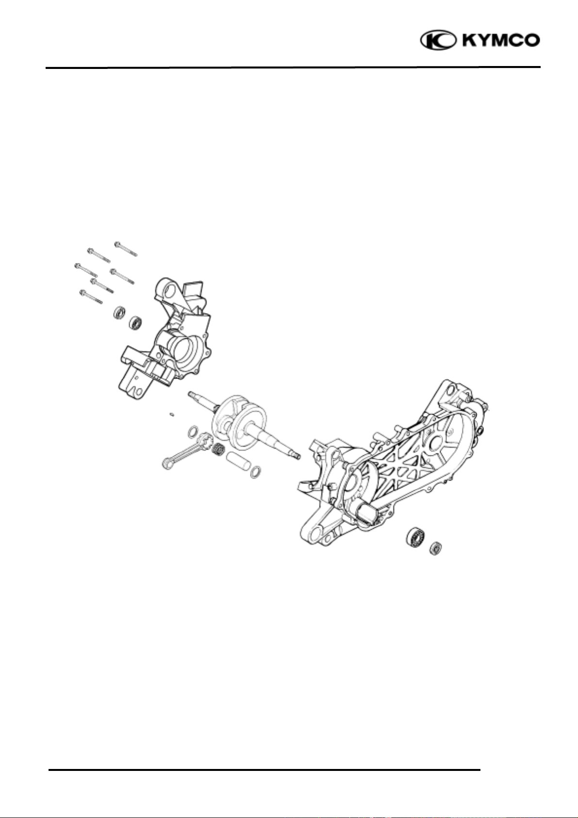
CRANKCASE/CRANKSHAFT
(Mongoose/KXR 50)
REMOVAL
Remove the crankcase attaching bolts.
Attach the crankcase puller on the right
crankcase and remove the right crankcase
from the left crankcase.
Crankcase puller E026
CRANKSHAFT REMOVAL
Attach the crankcase puller on the left
crankcase and remove the crankshaft from
the left crankcase.
Crankcase puller E026
When removing the crankshaft, do it
slowly and gently.
°Ø
Crankcase Puller
Crankcase Puller
Bolt
When separating the crankcase, the oil
seals must be removed. Replace the oil
seals with new ones.
°Ø
Special
Special
Page 9

11.CRANKSCASE/CRANKSHAFT
11-8
Mongoose/KXR 90/50
Remove the remaining bearing on the
crankshaft side using the universal bearing
puller.
Universal bearing puller E030
CRANKSHAFT INSPECTION
Measure the connecting rod big end side
clearance.
Service Limit: 0.6mm replace if over
Measure the connecting rod big end radial
clearance at two points in the X and Y
directions.
Service Limit: 0.04mm replace if over
Universal Bearing Puller
Special
Page 10

11.CRANKCASE/CRANKSHAFT
11-9
Mongoose/KXR 90/50
Measure the crankshaft runout.
Service Limit
A
B
0.100mm
replace if over
0.150mm
replace if over
Check the crankshaft bearings for excessive
play. The bearings must be replaced if they
are noisy or have excessive play.
CRANKSHAFT INSTALLATION
Wash the crankshaft in cleaning solvent and
then check for cracks or other faults.
Axial
Play
Play
Radial
• After check, apply clean engine oil to
all moving and sliding parts.
• Remove all gasket material from the
crankcase mating surfaces. Dress any
roughness or irregularities with an oil
stone.
°Ø
Page 11

11.CRANKSCASE/CRANKSHAFT
11-10
Mongoose/KXR 90/50
Drive a new crankshaft bearing into the right
crankcase.
Oil seal and bearing install E014
Drive a new crankshaft bearing into the left
crankcase.
Oil seal and bearing install E014
Install the crankshaft into the left crankcase.
Crankshaft install tool E016
Oil Seal And Bearing Install
Crankcase Install Tool
Special
Special
Oil Seal And Bearing Install
• Apply KYMCO ULTRA motor oil or
molybdenum disulfide to the crankshaft bearings and connecting rod big
end.
• Apply grease to the lip of the oil seal
and then install it.
°Ø
Special
Page 12

11.CRANKCASE/CRANKSHAFT
11-11
Mongoose/KXR 90/50
CRANKCASE ASSEMBLY
Install the dowel pins and a new gasket to
the crankcase mating surface.
Assemble the crankcase halves.
Crankshaft & crankcase install tool E024
The distance between the right crankcase oil
seal and crankcase surface is about 12.5±0.5
mm.
Dowel Pins
Crankshaft & Crankcase Install Tool
Special
When installing the oil seal, be careful to
press it with even force.
°Ø
Page 13

11.CRANKSCASE/CRANKSHAFT
11-12
Mongoose/KXR 90/50
The distance between the left crankcase oil
seal and crankcase surface is about 1.0mm.
Install and tighten the crankcase attaching
bolts.
Oil Seal
1.0mm
After assembly, check the crankshaft
for smooth operation.
°Ø
 Loading...