

Page 1

8. CYLINDER/PISTON
8-0
Mongoose/KXR 90/50
8
__________________________________________________________________________________
__________________________________________________________________________________
__________________________________________________________________________________
__________________________________________________________________________________
__________________________________________________________________________________
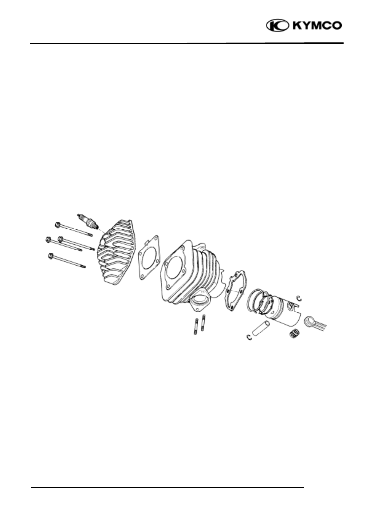
CYLINDER /PISTON
__________________________________________________________________________________
SERVICE INFORMATION (Mongoose/KXR 90)-------------------- 8- 3
SERVICE INFORMATION (Mongoose/KXR 50)-------------------- 8- 4
CYLINDER/PISTON (Mongoose/KXR 90) --------------------------- 8- 5
CYLINDER HEAD (Mongoose/KXR 50) ----------------------------- 8-10
CYLINDER/PISTON (Mongoose/KXR 50) --------------------------- 8-13
8
Page 2

8. CYLINDER/PISTON
8-1
Mongoose/KXR 90/50
Mongoose/KXR 90
Page 3
8. CYLINDER/PISTON
8-2
Mongoose/KXR 90/50
Mongoose/KXR 50
Page 4
8. CYLINDER/PISTON
8-3
Mongoose/KXR 90/50
SERVICE INFORMATION (Mongoose/KXR 90)
GENERAL INSTRUCTIONS
• The cylinder and piston can be serviced with the engine installed in the frame.
• Before disassembly, clean the engine to prevent dust from entering the engine.
• Remove all gasket material from the mating surfaces.
• Do not use a driver to pry between the cylinder and cylinder head, cylinder and crankcase.
• Do not damage the cylinder inside and the piston surface.
• After disassembly, clean the removed parts before inspection. When assembling, apply the
specified engine oil to movable parts.
SPECIFICATIONS
Standard (mm)
Service Limit (mm)
I.D.
47.00_ 47.01
47.1
Warpageæ0.05
Cylindricity
æ
0.05
True roundness
æ
0.05
Ring-to-groove
Top
0.015_ 0.055
0.09
clearance
Second
0.015_ 0.055
0.09
Top
0.15_ 0.3
0.5
Piston,
Ring end gap
Second
0.3_ 0.45
0.65
piston ring
Oil ring
0.2_ 0.7
0.9
Piston O.D.
46.97_ 46.99
46.9
Piston O.D. measuring position
4mm from bottom of skirt
æ
.
Piston-to-cylinder clearance
0.010_ 0.040
0.1
Piston pin hole I.D.
13.002_ 13.008
13.04
Piston pin O.D
12.994_ 17.000
12.96
Piston-to-piston pin clearance
0.002_ 0.014
0.02
Connecting rod small end I.D. bore
13.016_ 13.034
13.06
TROUBLESHOOTING
• When hard starting or poor performance at low speed occurs, check the crankcase breather for
white smoke. If white smoke is found, it means that the piston rings are worn, stuck or broken.
Compression too low or uneven
compression Excessive smoke from exhaust muffler
• Worn, stuck or broken piston rings • Worn or damaged piston rings
• Worn or damaged cylinder and piston • Worn or damaged cylinder and piston
Compression too high Abnormal noisy piston
• Excessive carbon build-up in combustion • Worn cylinder, piston and piston rings
chamber or on piston head
• Worn piston pin hole and piston pin
Cylinder
Page 5
8. CYLINDER/PISTON
8-4
Mongoose/KXR 90/50
SERVICE INFORMATION (Mongoose/KXR 50)
GENERAL INSTRUCTIONS
• The cylinder head, cylinder and piston can be serviced with the engine installed in the frame.
• Before disassembly, clean the engine to prevent dust from entering the engine.
• Remove all gasket material from the mating surfaces.
• Do not use a driver to pry between the cylinder and cylinder head, cylinder and crankcase.
• Do not damage the cylinder inside and the piston surface.
• After disassembly, clean the removed parts before inspection. When assembling, apply the
specified engine oil to movable parts.
SPECIFICATIONS
Item
Standard (mm)
Service Limit (mm)
Cylinder head warpage
æ
0.10
Piston O.D.(3mm from bottom of piston
38.960_ 38.965
38.90
Cylinder-to- piston clearance
0.035_ 0.05
0.10
Piston pin hole I.D.
12.002_ 12.008
12.03
Piston pin O.D.
11.994_ 12.0
11.98
Piston-to-piston pin clearance
0.002_ 0.014
0.03
Piston ring end gap (top/second)
0.10_ 0.25
0.40
Connecting rod small end I.D.
17.005_ 17.017
17.03
Cylinder bore
39.005_ 39.01
39.05
TORQUE VALUES
Cylinder head bolt 0.8_ 1.2kg-m
Spark plug 1.1_ 1.7kg-m
TROUBLESHOOTING
Compression too low, hard starting
or poor performance at low speed Abnormal noisy piston
• Leaking cylinder head gasket • Worn cylinder and piston
• Loose spark plug • Worn piston pin or piston pin hole
• Worn, stuck or broken piston and piston rings • Worn connecting rod small end bearing
• Worn or damaged cylinder and piston
Compression too high, overheating
or knocking Abnormal noisy piston rings
• Excessive carbon build-up in cylinder head • Worn, stuck or broken piston rings
or on piston head • Worn or damaged cylinder
Page 6
8. CYLINDER/PISTON
8-5
Mongoose/KXR 90/50
CYLINDER/PISTON
(Mongoose/KXR 90)
REMOVAL
Remove the cylinder head. (Refer to the
chapter 7)
Remove the two dowel pins and cylinder
head gasket.
Remove cam chain guide and then remove
cylinder.
Remove the cylinder gasket and dowel pins.
Clean any gasket material from the cylinder
surface.
Remove the piston pin clip.
Press the piston pin out of the piston and
remove the piston.
Dowel Pins
Gasket
Cam Chain Guide
Cylinder
Dowel Pins
Gasket
Piston
Clip
Piston Pin
Be careful not to drop foreign matters
into the crankcase.
°Ø
Place a clean shop towel in the crankcase
to keep the piston pin clip from falling
into the crankcase.
°Ø
Towel
Page 7

8. CYLINDER/PISTON
8-6
Mongoose/KXR 90/50
INSPECTION
Inspect the piston, piston pin and piston
rings.
Remove the piston rings.
Clean carbon deposits from the piston ring
grooves.
Inspect the piston wall for
wear/scratches/damage.
If any defects are found, replace the piston
with a new one.
Install the piston rings onto the piston and
measure the piston ring-to-groove clearance.
Service Limits: Top: 0.09mm replace if
over
2nd: 0.09mm replace if
over
Remove the piston rings and insert each
piston ring into the cylinder bottom.
Measure the piston ring end gap.
Service Limit: Top: 0.5mm replace if over
2nd: 0.65mm replace if over
Oil ring: 0.9mm replace if
over
Measure the piston pin hole I.D.
Service Limit: 13.04mm replace if over
Take care not to damage or break the
piston rings during removal.
°Ø
Use the piston head to push each piston
ring into the cylinder.
°Ø
Page 8

8. CYLINDER/PISTON
8-7
Mongoose/KXR 90/50
Measure the piston pin O.D.
Service Limit: 12.96mm replace if below
Measure the piston O.D.
Service Limit: 46.9mm replace if below
Measure the piston-to-piston pin clearance.
Service Limit: 0.02mm replace if over
CYLINDER INSPECTION
Inspect the cylinder bore for wear or damage.
Measure the cylinder I.D. at three levels of
top, middle and bottom at 90° to the piston
pin (in both X and Y directions).
Cylinder I.D.:
Service Limit: 47.1mm replace if over
Measure the cylinder-to-piston clearance.
Service Limit: 0.1mm repair or replace if
over
The true roundness is the difference
between the values measured in X and Y
directions. The cylindricity (difference
between the values measured at the three
levels) is subject to the maximum value
calculated.
Service Limits:
True Roundness: 0.05mm repair or replace
if over
Cylindricity: 0.05mm repair or replace if over
Take measurement at 10mm from the
bottom and 90° to the piston pin hole.
°Ø
4mm
Page 9

8. CYLINDER/PISTON
8-8
Mongoose/KXR 90/50
PISTON RING INSTALLATION
Install the piston rings onto the piston.
Apply engine oil to each piston ring.
Measure the connecting rod small end I.D.
Service Limit: 13.06mm replace if over
Measure the connecting rod to piston pin
clearance.
Service Limit: 0.06mm replace if over
Inspect the exhaust side and intake side
chain guides.
Wear/Damage _ Replace.
Second
Side Rail
Top
Side Rail
Oil Ring
• Be careful not to damage or break
the piston and piston rings.
• All rings should be installed with
the markings facing up.
• After installing the rings, they
should rotate freely without sticking.
°Ø
Intake Side Guide
Exhaust Side Guide
Page 10

8. CYLINDER/PISTON
8-9
Mongoose/KXR 90/50
PISTON INSTALLATION
Remove any gasket material from the
crankcase surface.
Install the piston, piston pin and a new
piston pin clip.
CYLINDER INSTALLATION
Install the dowel pins and a new cylinder
gasket on the crankcase.
Coat the cylinder bore, piston and piston
rings with clean engine oil.
Carefully lower the cylinder over the piston
by compressing the piston rings.
• Apply proper clean engine oil
around cylinder wall.
• Be careful not to damage or break
the piston rings.
• Stagger the ring end gaps at 120°
to the piston pin.
°Ø
Be careful not to drop foreign matters
into the crankcase.
°Ø
• Position the piston “IN” mark
on the intake valve side.
• Place a clean shop towel in the
crankcase to keep the piston pin clip
from falling into the crankcase.
°Ø
“IN” Mark
IN
Page 11

8. CYLINDER/PISTON
8-10
Mongoose/KXR 90/50
CYLINDER HEAD
(Mongoose/KXR 50)
REMOVAL
Remove the spark plug cap.
Remove the exhaust muffler. (!2-7)
Remove the three bolts attaching the fan
cover to remove the fan cover.
Remove the bolt attaching the engine hood
to remove the engine hood.
The installation sequence is the reverse of
removal.
Remove the spark plug.
Remove the cylinder head bolts and the
cylinder head.
Remove the cylinder head gasket.
Cylinder head Bolts
Spark Plug Cap
Fan Cover/Engine Hood
Cylinder Head
Spark Plug
Loosen the bolts diagonally in 2 or 3
times.
°Ø
Page 12

8. CYLINDER/PISTON
8-11
Mongoose/KXR 90/50
COMBUSTION CHAMBER
DECABONIZING
Remove the carbon deposits from the
combustion chamber
CYLINDER HEAD INSPECTION
Check the cylinder head for warpage with a
straight edge and feeler gauge.
Service Limit: 0.10mm replace if over
CYLINDER HEAD INSTALLATION
Install the cylinder head on the cylinder
properly.
Install a new cylinder head gasket onto the
cylinder.
Cylinder head Gasket
Combustion Chamber
Mating Surface
Avoid damaging the combustion chamber wall and cylinder mating surface.
°Ø
Be careful not to damage the mating
surfaces.
°Ø
Page 13

8. CYLINDER/PISTON
8-12
Mongoose/KXR 90/50
Cylinder Head Bolts Installation
Install and tighten the cylinder head bolts
diagonally in 2 or 3 times.
Torque: 0.8_ 1.2kg-m
Install the spark plug.
Torque: 1.1_ 1.7kg-m
Install the engine hood and fan cover.
Perform the following inspections after
installation:
• Compression test
• Abnormal engine noise
• Cylinder air leaks
Cylinder head Bolts
Bolts
Cylinder Head
Spark Plug
Spark Plug
Engine Hood
Fan Cover
Page 14

8. CYLINDER/PISTON
8-13
Mongoose/KXR 90/50
CYLINDER/PISTON
(Mongoose/KXR 50)
CYLINDER REMOVAL
Remove the cylinder head.
Remove the exhaust muffler. (See page 2-7)
Remove the reed valve. (See page 5-16)
Remove the cylinder.
Remove the cylinder gasket.
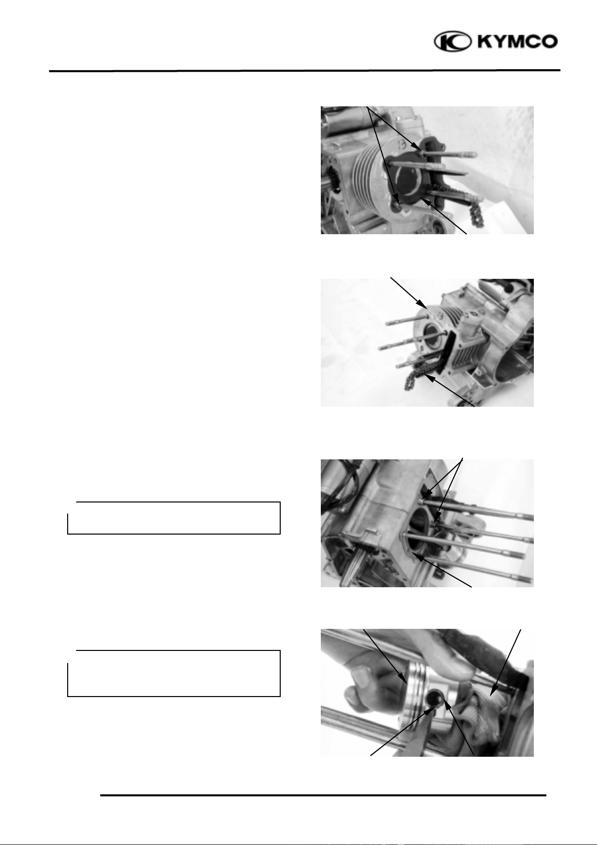
PISTON REMOVAL
Remove the piston pin clip to remove the
piston pin and piston.
Spread each piston ring and remove by
lifting it up at a point just opposite the gap.
Remove the expander.
Piston Pin Clip
Piston
Piston Pin
Cylinder
• Do not damage or scratch the piston.
• Do not apply side force to the
connect-ing rod when removing the
piston pin.
• Place clean shop towels in the crank-
case to keep the piston pin clip from
falling into the crankcase.
°Ø
Do not pry between the cylinder and
crankcase or strike the fins.
°Ø
Page 15

8. CYLINDER/PISTON
8-14
Mongoose/KXR 90/50
CYLINDER/PISTON INSPECTION
Check the cylinder and piston for wear or
damage.
Clean carbon deposits from the exhaust port
area.
Measure the cylinder bore at three levels of
A, B and C in both X and Y directions.
Avoid the port area. Take the maximum
figure measured to determine the cylinder
bore.
Service Limit: 39.05mm replace if over
Inspect the top of the cylinder for warpage.
Service Limit: 0.10mm replace if over
Middle
Bottom
Top
Be careful not to damage the cylinder
inside wall.
°Ø
Page 16

8. CYLINDER/PISTON
8-15
Mongoose/KXR 90/50
Measure the piston O.D. at a point 3mm
from the bottom of the piston skirt.
Service Limit: 38.90mm replace if below
Measure the piston-to-cylinder clearance.
Service Limit: 0.10mm replace if over
Measure the piston pin hole I.D.
Service Limit: 12.03mm replace if over
Measure the piston pin O.D.
Service Limit: 11.98mm replace if below
Measure the piston-to-piston pin clearance.
Service Limit: 0.03mm replace if over
A Mark
The cylinder has an “A” mark or no
mark on it. When replacing the cylinder
with a new one, use a cylinder having
the same mark as the old one.
°Ø
Page 17

8. CYLINDER/PISTON
8-16
Mongoose/KXR 90/50
PISTON RING INSPECTION
Measure each piston ring end gap.
Service Limits: Top/Second
0.40mm replace if over
CONNECTING ROD SMALL END
INSPECTION
Install the piston pin and bearing in the
connecting rod small end and check for
excessive play.
Measure the connecting road small end I.D.
Service Limit: 17.03mm replace if over
PISTON/CYLINDER INSTALLATION
First install the expander in the second ring
groove.
Then install the top and second rings in their
respective ring grooves.
The piston rings should be pressed into the
grooves with even force.
After installation, check and make sure that
each ring is flush with the piston at several
points around the ring.
A ring that will not compress means that the
ring groove has carbon deposits in it and
should be cleaned.
Expander
Top Ring (1st Ring)
Piston
Second Ring
Set each piston ring squarely into the
cylinder using the piston and measure
the end gap.
°Ø
Page 18

8. CYLINDER/PISTON
8-17
Mongoose/KXR 90/50
Install a new cylinder gasket on the mating
surface between the cylinder and crankcase.
Position the piston “IN” mark on the intake
valve side.
Make sure that the ring end gaps are aligned
with the piston ring pins in the ring grooves.
Lubricate the cylinder inside and piston
rings with engine oil and install the piston
into the cylinder while compressing the
piston rings.
Install the cylinder head.
Torque: 0.8_ 1.2kg-m
The installation sequence is the reverse of
removal .
Cylinder Gasket
Ring Pins
“IN” Mark
Be careful not to damage the piston.
°Ø
 Loading...