

Page 1

17. IGNITION SYSTEM
17-0
Mongoose/KXR 250
17
__________________________________________________________________________________
__________________________________________________________________________________
__________________________________________________________________________________
__________________________________________________________________________________
__________________________________________________________________________________
IGNITION SYSTEM
__________________________________________________________________________________
SERVICE INFORMATION -------------------------------------------- 17- 2
TROUBLESHOOTING ------------------------------------------------- 17- 3
IGNITION UNIT /CHANGE GEAR CONTROL INSPECTION --- 17- 4
IGNITION COIL INSPECTION --------------------------------------- 17- 6
PULSER COIL----------------------------------------------------------- 17- 7
17
Page 2
17. IGNITION SYSTEM
17-1
Mongoose/KXR 250
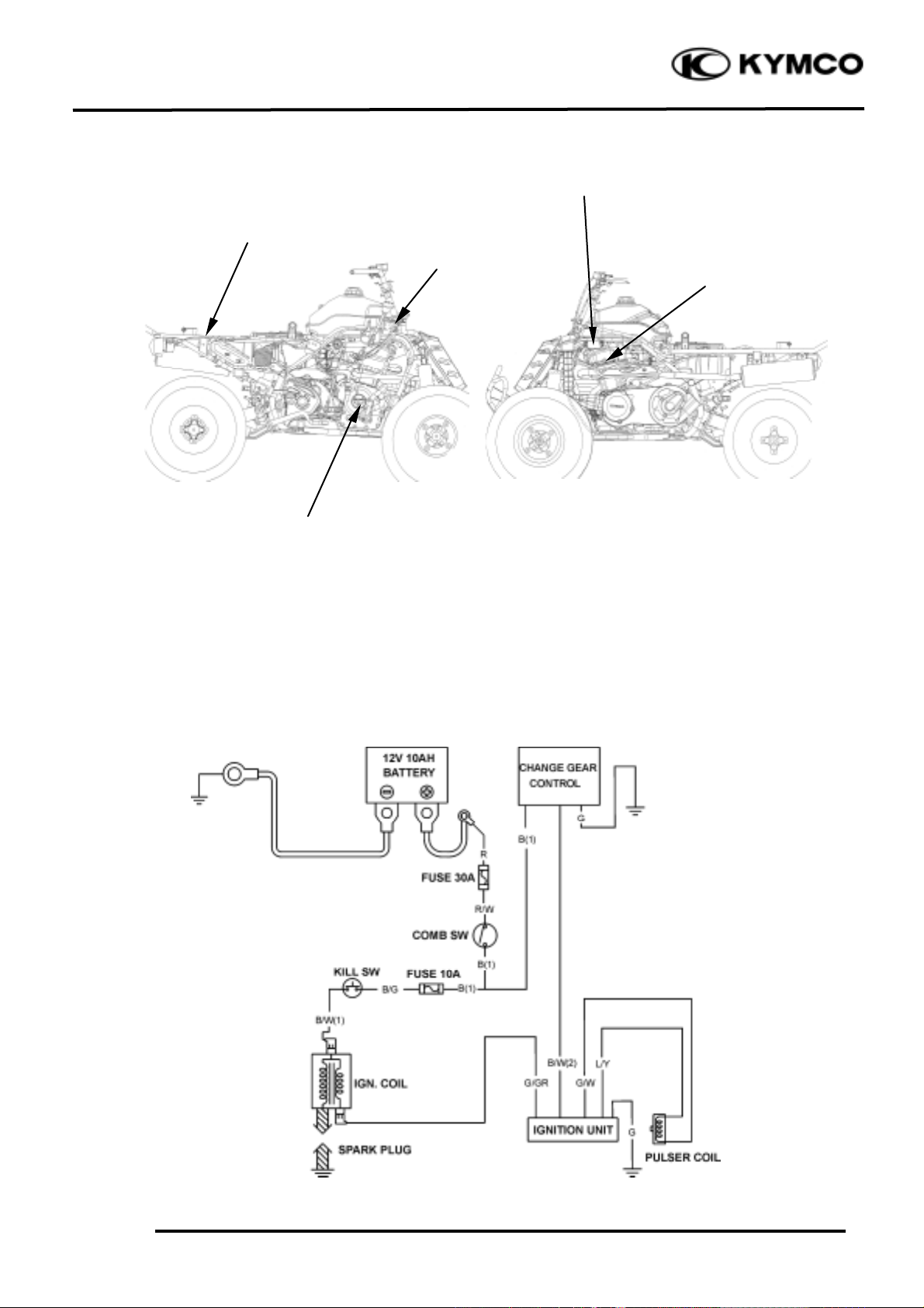
IGNITION CIRCUIT
Ignition Switch
Ignition Unit/Change Gear Control
A.C. Generator/ Pulser Coil
Spark Plug
Ignition Coil
Page 3
17. IGNITION SYSTEM
17-2
Mongoose/KXR 250
SERVICE INFORMATION
GENERAL INSTRUCTIONS
• Check the ignition system according to the sequence specified in the Troubleshooting.
• The ignition system adopts ignition unit, change gear control and the ignition timing cannot be
adjusted.
• If the timing is incorrect, inspect the ignition unit, A.C. generator, change gear control and replace
any faulty parts. Inspect the ignition unit with a ignition unit tester
• Loose connector and poor wire connection are the main causes of faulty ignition system. Check
each connector before operation.
• Use of spark plug with improper heat range is the main cause of poor engine performance.
• The inspections in this section are focused on maximum voltage. The inspection of ignition coil
resistance is also described in this section.
• Inspect the spark plug referring to chapter 3.
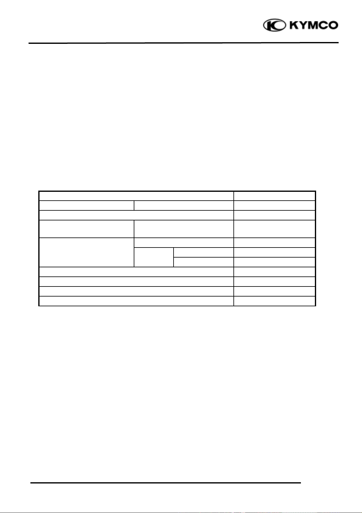
SPECIFICATIONS
Item
Standard
Spark plug
Standard type
DPR7EA-9
Spark plug gap
0.6_ 0.7mm
Ignition timing
“F” mark
Full advance
5º±1ºBTDC/2000RPM
Primary coil
3.4_ 4.1W
Ignition coil resistance (20¢J)
Secondary
without plug cap
14.45KW
coil
with plug cap
19.8KW
Pulser coil resistance (20¢J)
105_ 110W
Ignition coil primary side max. voltage
14V
Pulser coil max. voltage
1.6V
Exciter coil max. voltage
14V
TESTING INSTRUMENT
Commercially available electric tester with resistance over 10MW/CDV.
Page 4

17. IGNITION SYSTEM
17-3
Mongoose/KXR 250
TROUBLESHOOTING
High voltage too low No high voltage
• Weak battery or low engine speed • Faulty ignition switch
• Loose ignition system connection • Faulty ignition unit
• Faulty ignition unit • Poorly connected or broken ignition unit
ground wire
• Faulty ignition coil •Dead battery or faulty regulator/rectifier
• Faulty pulser coil • Faulty ignition coil connector
Normal high voltage but no spark at plug • Faulty pulser coil
• Faulty spark plug
• Electric leakage in ignition secondary circuit
• Faulty ignition coil
Good spark at plug but engine won‘t start
• Faulty ignition unit or incorrect ignition timing
• Faulty change gear control unit
• Improperly tightened A.C. generator flywheel
Page 5

17. IGNITION SYSTEM
17-4
Mongoose/KXR 250
IGNITION UNIT /CHANGE
GEAR CONTROL INSPECTION
Remove the seat. (Refer to the chapter 2)
Disconnect the ignition unit coupler and
remove the ignition unit.
Disconnect the change gear control coupler
and remove the change gear control.
Measure the resistance between the
terminals using the electric tester.
IGNITION UNIT INSPECTION
Testing Range (at 20°C)
Note: The readings in this table are taken
with a YF-3501 Tester.
Unit: W
Ignition Unit
Change Gear Control
• Due to the semiconductor in circuit, it is
necessary to use a specified tester for
accurate testing. Use of an improper
tester in an improper range may give
false readings.
• Use a YF-3501 Electric Tester.
• In this table, “Needle swings then
returns” indicates that there is a charging
current app lied to a condenser. The needle
will then remain at “°¤ ” unless the
condenser is discharged.
°Ø
Probe⊕
(-)Probe
Blue/
Yellow
Green /
Gray
Black /
White
Green/
White
Black/
Yellow
Green
Blue/
Yellow
°¤
10.56M
90.4K
10.56M
46K
Green /
Gray
12.73M
°¤
12.73M
°¤
12.73M
Black /
White
°¤°¤°¤
999
°¤
Green/
White
90.4K
°¤
10.56M
10.56M
46K
Black/
Yellow
°¤°¤999°¤°¤
Green
44.4K
°¤
10.56M
44.4K
10.56M
Ignition Unit
Page 6

17. IGNITION SYSTEM
17-5
Mongoose/KXR 250
Test the ignition unit using the ignition unit
tester.
Connect the special connector to the ignition
unit coupler and ignition unit tester.
Switch Range
Good CDI
Faulty CDI
1. OFF
2. P
3. EXT
4. ON1
5. ON2
No spark
No spark
No spark
Good spark
Good spark
ææ
ææ
Good spark
No spark
No spark
If the ignition unit is faulty, replace it with a
new one.
CHANGE REAR CONTROL
INSPECTION
Testing Range(at 20°C)
Note: The readings in this table are taken
with a YF-3501 Tester.
Probe⊕
(-)Probe
Green
Yellow/
Brown
Light Green/
Red
Green/
Pink
Green/
Yellow
Black/
White
Black
Green
14
°¤
°¤
7.85M
7.85M
10K
Yellow/
Brown
18
°¤
°¤
7.85M
7.85M
10K
Light Green/
Red
7.85M
7.85M
11
°¤
°¤
7.85M
Green/
Pink
7.85M
7.85M
9
°¤
°¤
7.85M
Green/
Yellow
°¤°¤°¤°¤°¤
Black/
White
°¤°¤°¤
°¤11°¤
Black
10K
10K
°¤
°¤
7.85M
7.85M
Spark
Window
Ignition Coil
CDI Unit
Spark Plug
CDI Tester
Operate the ignition unit tester by
following the manufacturer‘s
instructions.
°Ø
Change Gear Control
Unit: W
Page 7

17. IGNITION SYSTEM
17-6
Mongoose/KXR 250
IGNITION COIL INSPECTION
CONTINUITY TEST
Remove the front fender. (Refer to the
chapter 2)
Remove the spark plug cap. (Refer to the
chapter 6)
Disconnect the ignition coil wires.
Measure the resistance between the ignition
coil primary coil terminals.
Resistance: 3.4_ 4.1W/20_C
Remove the spark plug cap and measure the
secondary coil resistance between the spark
plug wire and the primary coil terminal.
Resistance:
(with plug cap): 19.8KW/20_C
(without plug cap): 14.45KW/20_C
Measure the spark plug cap resistance.
Remove the spark plug cap and measure the
spark plug resistance.
Resistance: 4.2_ 5.2KW/20_C
Ignition Coil
This test is to inspect the continuity of
ignition coil.
°Ø
This test is for reference only. Accurate
test should be performed with a CDI
tester.
°Ø
Measure the resistance in the XKW range
of the electric tester.
°Ø
Page 8

17. IGNITION SYSTEM
17-7
Mongoose/KXR 250
PERFORMANCE TEST
Test the performance with a ignition unit
tester.
If the spark is weak, inspect the spark plug
and CDI unit. If both of them are normal,
replace the ignition coil with a new one.
PULSER COIL
INSPECTION
Remove the front fender. (Refer to the
chapter 2)
Disconnect the pulser coil wire coupler and
measure the resistance between the blue/
yellow and green/white wire terminals.
Resistance: 105_ 110W/20_C
Refer to the “A.C.
GENERATOR/FLYWHEEL” section in the
chapter 16 to remove or install.
Ignition Coil
CDI Unit
Spark Plug
CDI Tester
• Operate the ignition unit tester by
following the manufacturer‘s
instructions.
• Use the special connector to connect
the ignition unit.
°Ø
 Loading...