

Page 1

14. FRONT WHEEL/FRONT SUSPENSION/
STEERING SYSTEM
14-0
Mongoose/KXR 250
14
__________________________________________________________________________________
__________________________________________________________________________________
__________________________________________________________________________________
__________________________________________________________________________________
__________________________________________________________________________________
FRONT WHEEL/
FRONT SUSPENSION\STEERING SYSTEM
__________________________________________________________________________________
SERVICE INFORMATION -------------------------------------------- 14- 2
TROUBLESHOOTING ------------------------------------------------- 14- 2
FRONT WHEEL--------------------------------------------------------- 14- 3
FRONT WHEEL HUB -------------------------------------------------- 14- 4
FRONT SUSPENSION ------------------------------------------------- 14- 7
TIE-ROD ----------------------------------------------------------------- 14-11
HANDLEBAR ----------------------------------------------------------- 14-13
STEERING COLUMN -------------------------------------------------- 14-15
14
Page 2
14. FRONT WHEEL/FRONT SUSPENSION/
STEERING SYSTEM
14-1
Mongoose/KXR 250
Page 3
14. FRONT WHEEL/FRONT SUSPENSION/
STEERING SYSTEM
14-2
Mongoose/KXR 250
SERVICE INFORMATION
GENERAL INSTRUCTIONS
• Jack the machine front wheel off the ground and be careful to prevent the machine from falling
down.
• During servicing, keep oil or grease off the brake disk
• Inspect the brake system before riding.
SPECIFICATIONS
Item
Standard (mm)
Service Limit (mm)
Radialæ2.0
Axialæ2.0
Tie rod length
299.5±0.5
æ
Rod-end (tie rod) angle
180ºæ
TORQUE VALUES
Steering stem nut 6.0_ 8.0kgf-m
Front swing arm nut 4.0_ 5.0kgf-m
Front wheel nut 5.0_ 6.0kgf-m
Front wheel hub nut 6.0~8.0kgf-m
Steering knuckle nut 3.0_ 4.0kgf-m
Front shock absorber upper
mount bolt 3.5_ 4.5kgf-m
Front shock absorber lower
mount bolt 3.5_ 4.5kgf-m
SPECIAL TOOLS
Oil seal and bearing install E014
TROUBLESHOOTING
Hard steering (heavy) Front wheel wobbling
•Insufficient tire pressure • Bent rim
• Excessive wheel bearing play
• Bent spoke plate
• Faulty tire
Steers to one side or does not track straight • Improperly tightened axle nut
• Uneven front shock absorbers Soft front shock absorber
• Bent front arm • Weak shock springs
• Bent steering knuckle • Insufficient damper oil
Front shock absorber noise
• Slider bending
• Loose arm fasteners
• Lack of lubrication
Front wheel rim run out
Page 4
14. FRONT WHEEL/FRONT SUSPENSION/
STEERING SYSTEM
14-3
Mongoose/KXR 250
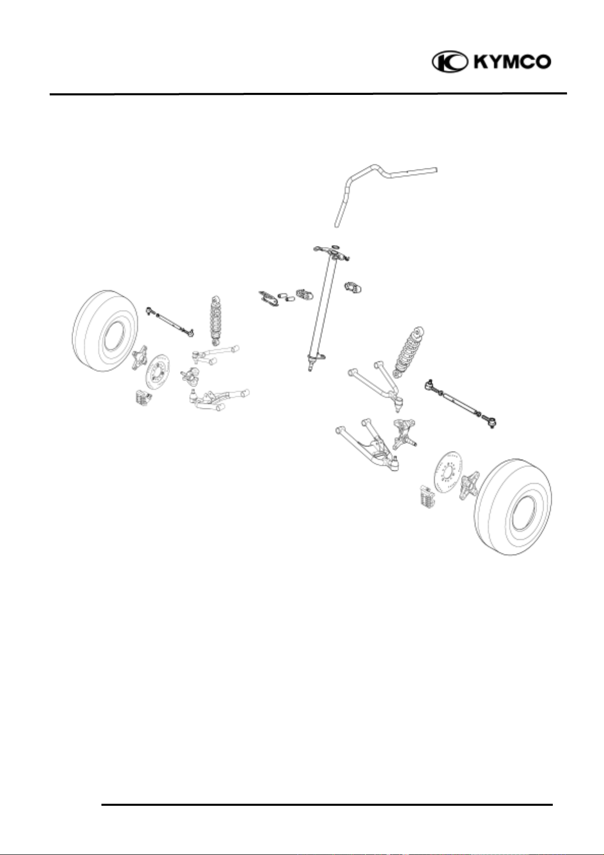
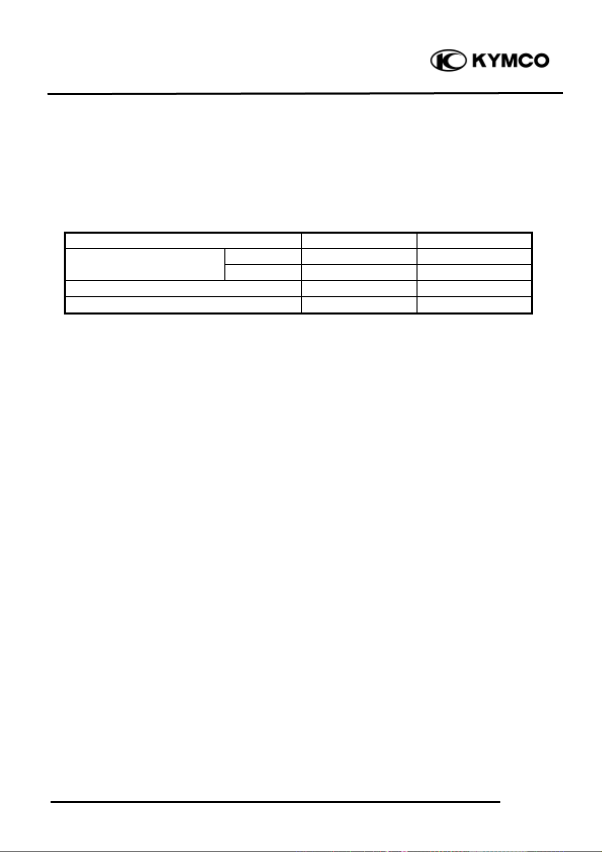
FRONT WHEEL
REMOVAL AND INSPECTION
Place the machine on a level place.
Remove four nuts attaching the front wheel
hub and front wheel.
Elevate the front wheels by placing a
suitable stand under the frame.
Measure the wheel run out.
Replace wheel or check bearing play if out
of specification
Rim run out limits:
Vertical: 2.0mm
Lateral: 2.0mm
INSTALLATION
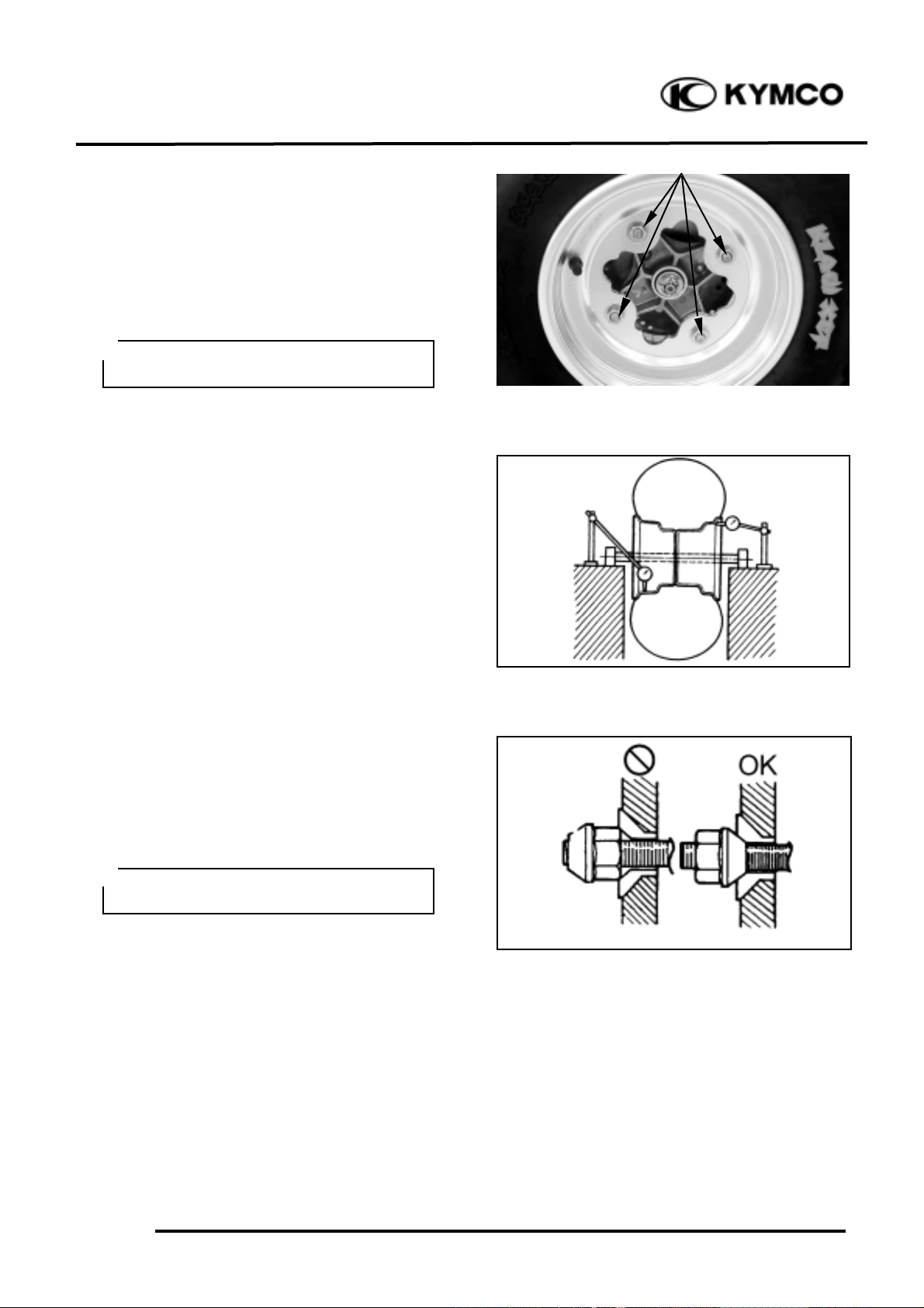
When reinstalling a wheel, tighten the wheel
nuts in a crisscross (rather than a circular)
pattern.
Torque: 5.0_ 6.0kgf-m
Support the machine securely so
there is no danger of it falling over.
°Ø
Be sure the tapered side of the wheel
nuts face the wheel rim.
°Ø
Nuts
Page 5
14. FRONT WHEEL/FRONT SUSPENSION/
STEERING SYSTEM
14-4
Mongoose/KXR 250
FRONT WHEEL HUB
REMOVAL AND INSPECTION
Place the machine on a level place.
Remove the front wheel (!14-3) and
caliper. (!13-8)
Elevate the front wheels by placing a
suitable stand under the frame.
Remove the cotter pin.
Remove nut attaching the front wheel hub
and then remove front wheel hub.
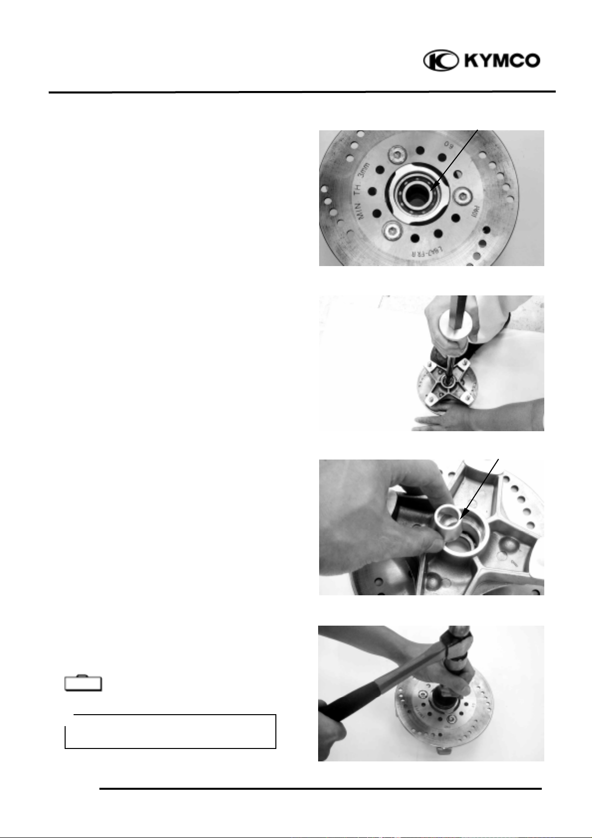
DISASSEMBLY
Remove the outside collars.
Inspect the dust seals for wear or damage.
If any defects are found, replace the dust
seal with a new one.
Remove the dust seals by a flat-head screw
driver.
Inspect the bearings for allow play in the
front wheel hub or the wheel turns roughly.
Support the machine securely so
there is no danger of it falling over.
°Ø
Place a wood block against the outer
edge to protect this edge.
°Ø
Nuts
Cotter Pin
Outside Collar
Dust Seal
Outside Collar
Dust Seal
Bearing
Page 6
14. FRONT WHEEL/FRONT SUSPENSION/
STEERING SYSTEM
14-5
Mongoose/KXR 250
If any defects are found, replace the bearings
Remove the bearings using a general bearing
puller.
Remove the distance collar from the front
wheel hub.
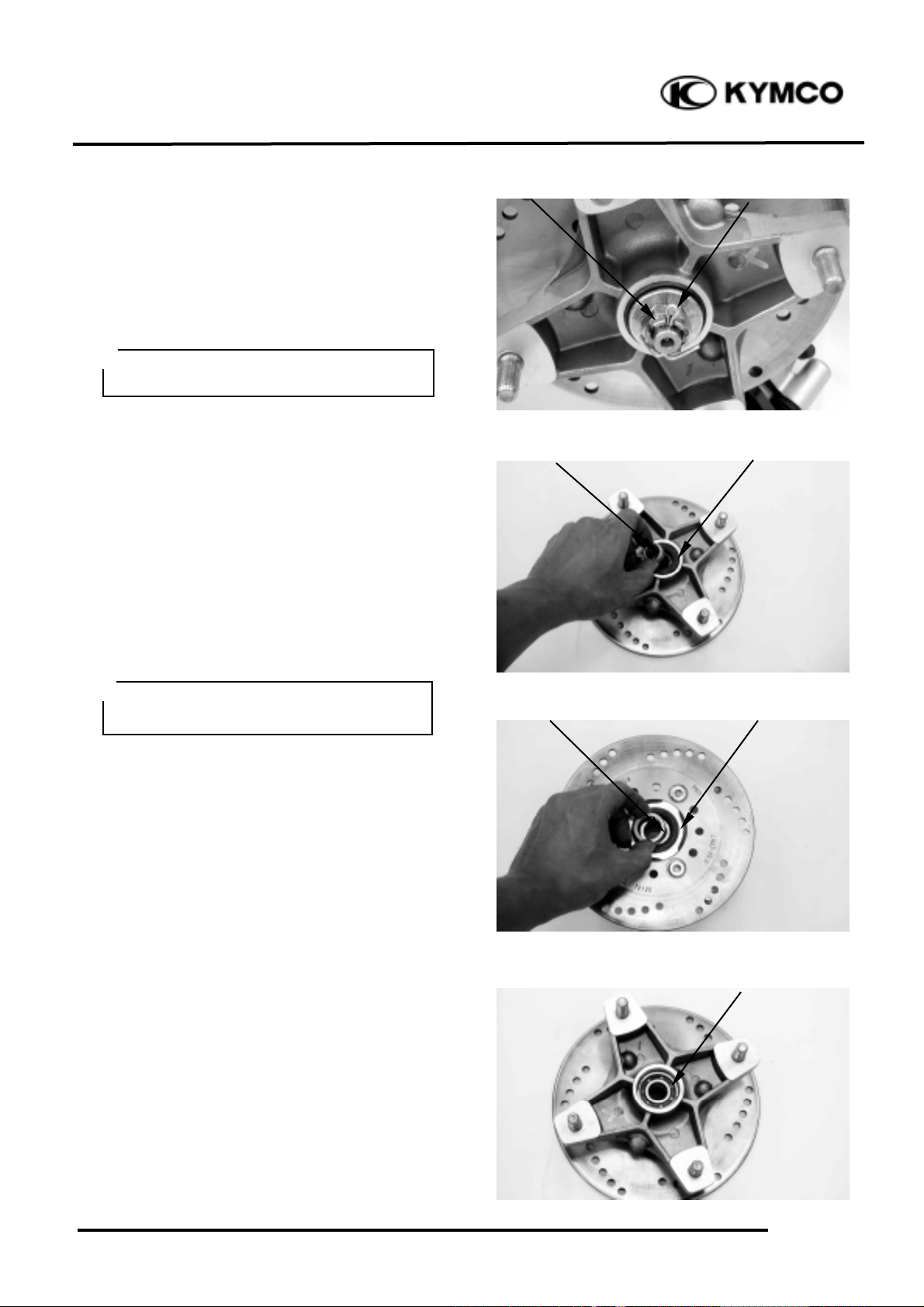
ASSEMBLY
Install the left new bearing and dust seal into
the front wheel hub.
Oil seal and bearing install E014
Special
Apply the grease onto the oil seal lips,
bearing.
°Ø
Bearing
Distance Collar
Page 7

14. FRONT WHEEL/FRONT SUSPENSION/
STEERING SYSTEM
14-6
Mongoose/KXR 250
Install the distance collar.
Install the right new bearing and dust seal
into the front wheel hub.
Oil seal and bearing install E014
INSTALLATION
Reverse the “FRONT WHEEL HUB
REMOVAL AND INSPECTION”
procedures.
Tighten the front wheel hub nut.
Torque: 5.0_ 6.0kgf-m
Install the cotter pin and band ends of cotter
pin.
Be sure the tapered side of the distance
collar face the wheel.
°Ø
Apply the grease onto the oil seal lips,
bearing.
°Ø
• Do not allow the bearings to tilt
while driving them in.
• Do not strike the center race or
balls of the bearing. Contact should be
made only with the outer race.
• Pack all bearing cavities with
grease.
• Drive in the bearing squarely
°Ø
Special
Apply grease onto the bearing and dust
seal lips of the wheel panel.
°Ø
Always use a new cotter pin.
°Ø
Distance Collar
Page 8

14. FRONT WHEEL/FRONT SUSPENSION/
STEERING SYSTEM
14-7
Mongoose/KXR 250
FRONT SUSPENSION
REMOVAL AND INSPECTION
Elevate the front wheels by placing a
suitable stand under the frame.
Remove the front wheel (!14-3), caliper
(!13-8) and front wheel hub. (!14-4)
Remove the cotter pins, washer and nuts
attaching tie-rod, upper and lower front arm.
Disconnect the upper front arm from the
steering knuckle.
Remove the front shock absorber upper mount
and lower mount bolts, then remove the front
shock absorber and bush.
Disconnect the tie-rod and lower front arm
from steering knuckle, then remove steering
knuckle.
Inspect the steering knuckle for cracks,
pitting or damage.
If any defects are found, replace the steering
knuckle with a new one.
Support the machine securely so there is
no danger of it falling over.
°Ø
Nut
Cotter Pin
Nuts
Cotter Pin
Upper Front Arm
Upper Front Arm
Bolts
Lower Front Arm
Tie-rod
Page 9

14. FRONT WHEEL/FRONT SUSPENSION/
STEERING SYSTEM
14-8
Mongoose/KXR 250
Inspect the shock absorber rod.
Bends/damage _Replace the shock absorber
assembly.
Inspect the shock absorber.
Oil leaks _Replace the shock absorber
assembly.
Inspect the spring of the shock absorber by
move the spring up and down.
Fatigue _Replace the shock absorber
assembly.
Inspect bush.
Wear/damage _Replace.
Check the upper front arm brackets of the
frame.
If bent, cracked or damaged, repair or
replace the frame.
Check the tightening torque of the front
arms securing nuts.
Torque: 40_ 5.0kgf-m
Check the upper front arm side play by
moving it from side to side.
If side play noticeable, replace the inner
collars and bushes as a set. as a set.
Check the front arm vertical movement by
moving it up and down.
If vertical movement is tight, binding or
rough, replace the inner collars and bushes
as a set.
Remove the band and then disconnect the
front brake fluid tube from the upper front
arm.
Remove the two nuts and two bolts
attaching the upper front arm, then remove
the upper front arm and bushes.
Bush
Shock Absorber
Band
Front Brake Fluid Tube
Bolts
Page 10

14. FRONT WHEEL/FRONT SUSPENSION/
STEERING SYSTEM
14-9
Mongoose/KXR 250
Inspect the front arm.
Cracks/bends/damage _Replace.
Inspect bushes.
Wear/damage _Replace.
Check the lower front arm brackets of the
frame.
If bent, cracked or damaged, repair or
replace the frame.
Check the tightening torque of the front
arms securing nuts.
Torque: 4.0_ 5.0kgf-m
Check the lower front arm side play by
moving it from side to side.
If side play noticeable, replace the inner
collar and bushes as a set.
Check the lower front arm vertical
movement by moving it up and down.
If vertical movement is tight, binding or
rough, replace the inner collar and bushes as
a set.
Remove the two nuts and two bolts
attaching the lower front arm, then remove
the lower front arm and bushes.
Do not attempt to straighten a bent arm,
this may dangerously weaken the arm.
°Ø
Bushes
Bolts
Page 11

14. FRONT WHEEL/FRONT SUSPENSION/
STEERING SYSTEM
14-10
Mongoose/KXR 250
Inspect the lower front arm.
Cracks/bends/damage _Replace.
Inspect bushes.
Wear/damage _Replace.
INSTALLATION
Reverse the “FRONT SUSPENSION
REMOVAL AND INSPECTION”
procedures.
Install the lower and upper front arms nuts
onto the frame and tighten the nuts.
Torque: 4.0_ 5.0kgf-m
Install the steering knuckle onto the upper
and lower front arms and tighten the nuts.
Torque: 3.0_ 4.0kgf-m
Install the tie-rod and washer onto the
steering knuckle and tighten the nut.
Torque: 3.0_ 4.0kgf-m
Install the all cotter pins and band ends of
cotter pins.
Apply the grease onto the bush, then install
the shock absorber and tighten the upper
mount and lower mount bolts.
Torque: 3.5_ 4.5kgf-m
Install the front wheel hub (!14-6), caliper
(!13-10) and front wheel. (!14-3)
Do not attempt to straighten a bent arm,
this may dangerously weaken the arm.
°Ø
Apply the grease onto the bushes and
inner collars
°Ø
Always use a new cotter pin.
°Ø
Bushes
Page 12

14. FRONT WHEEL/FRONT SUSPENSION/
STEERING SYSTEM
14-11
Mongoose/KXR 250
TIE-ROD
REMOVAL AND INSPECTION
Remove the cotter pin and nut attaching the
tie-rod and steering column.
Remove the cotter pin and nut attaching the
tie-rod and steering knuckle.
Then remove tie-rods.
Inspect the tie-rod.
Bend/damage _Replace.
Check the tie-rod end movement.
Tie-rod end exists free play or turns
roughly _Replace.
Check the tapered surface of the tie-rod end.
Pitting/wear/damage _Replace.
Adjust the tie-rod length.
Adjustment steps:
(The following procedures are done on both
tie-rods, right and left.)
Loosen the lock nuts.
Adjust the tie-rod length by tuning both tie-
rod ends.
Tie rod length: 299.5±0.5mm
Lock Nut
Lock Nut
Indentation Surface
Nut
Cotter Pin
Nut
Cotter Pin
Page 13

14. FRONT WHEEL/FRONT SUSPENSION/
STEERING SYSTEM
14-12
Mongoose/KXR 250
Set the rod-end (steering column side) in an
angle where the indentation surface of the
tie-rod is parallel to the rod-end shaft, and
then tighten the lock nut.
Torque: 2.5_ 3.5kgf-m
Set the other rod-end (knuckle arm side) in
an angle as shown (right-hand tie-rod and
left-had tie-rod), and then tighten the lock
nut.
Rod-end (tie rod) angle: 180
º
Torque: 2.5_ 3.5kgf-m
INSTALLATION
Reverse the “REMOVAL AND
INSPECTION” procedures.
Install the tie-rod and washer onto the
steering knuckle and steering column, then
tighten the nuts.
Torque: 3.0_ 4.0kgf-m
Install the all cotter pins and band ends of
cotter pins.
After making adjustment on both tie rods
be sure to mark them R and L for
identification.
°Ø
The threads on both rod-end must be of
the same length.
°Ø
To Steering Column
To Knuckle Arm
Always use a new cotter pin.
°Ø
Be sure that the rod-end on the
indentation surface side is connected to
the steering knuckle.
°Ø
Indentation Surface
Page 14

14. FRONT WHEEL/FRONT SUSPENSION/
STEERING SYSTEM
14-13
Mongoose/KXR 250
HANDLEBAR
REMOVAL AND INSPECTION
Remove the following parts:
Seat, front cover, center cover, front fender
and handlebar cover.
Refer to the “FENDERS” section in the
CHAPTER 2
Remove the right and left master cylinder
and remove bands then disconnect the rear
and front fluid tube from the handlebar.
Remove the two screws and remove the
handlebar switch.
Remove the two screws and remove throttle
unit.
Remove the four handlebar holder bolts and
remove the handlebar.
INSPECTION
Inspect the handlebar.
Cracks/bends/damage _Replace.
Bolts
Brake Fluid Tube
Screws
Screws
Bolts
Page 15

14. FRONT WHEEL/FRONT SUSPENSION/
STEERING SYSTEM
14-14
Mongoose/KXR 250
INSTALLATION
Install handlebar and handlebar holder, then
tighten the four bolts.
Torque: 1.8_ 2.5kgf-m
Install the handlebar switch by aligning the
pin on the handlebar switch with the hole in
the handlebar and then tighten the two
screws.
Place the right and left brake master cylinder
on the handlebar and install the master
cylinder holder with the “UP” mark facing
up, aligning the punch mark on the
handlebar with the holder joint seam. First
tighten the upper bolt and then tighten the
lower blot.
Torque: 0.8 ~ 1.2kg-m
• Align the mark on the handlebar
with the lower handlebar holder surface.
• Be sure the upper handlebar
holder mark face to front.
• Fist tighten the bolts on the front
side of the handlebar holder, and then
tighten the bolts on the rear side.
°Ø
Mark
Holder Surface
Forward Mark
Hole
Pin
Joint Seam
Punch Mark
“UP” Mark
Page 16

14. FRONT WHEEL/FRONT SUSPENSION/
STEERING SYSTEM
14-15
Mongoose/KXR 250
Install the throttle unit by aligning the upper
holder lip with the mark in the handlebar
and then install the lower holder and tighten
the two screws.
STEERING COLUMN
REMOVAL AND INSPECTION
Remove handlebar. (!14-13)
Remove the two bolts and remove the cable
holder, steering brackets, collars and dust
seal.
Mark
Upper Holder Lip
Bolts
Collars
Steering Bracket
Steering Bracket
Dust Seal
Page 17

14. FRONT WHEEL/FRONT SUSPENSION/
STEERING SYSTEM
14-16
Mongoose/KXR 250
Remove the cotter pins and nuts attaching
the tie-rods, then disconnect the tie-rods
from the steering column.
Remove the cotter pin and nut attaching the
steering column under the frame body, then
remove steering column and collar.
Inspect the collar, dust seals, snap ring
(under the dust seal) and bearing.
Wear/damage _Replace.
Cotter Pin
Nut
Cotter Pin
Nut
Dust Seal
Collar
Bearing
Dust Seal
Snap Ring
Page 18

14. FRONT WHEEL/FRONT SUSPENSION/
STEERING SYSTEM
14-17
Mongoose/KXR 250
Inspect the steering column.
Bends/damage _Replace.
Inspect the steering brackets and oil seal.
Wear damage _Replace.
INSTALLATION
Reverse the “REMOVAL” procedures.
Install the steering column and collar, then
tighten the nut under the frame body.
Torque: 6.0_ 8.0kgf-m
Install the cotter pin and band ends of cotter
pin.
Assembly the steering column and tighten
the two bolts.
Torque: 1.8_ 2.5kgf-m
Install the tie rods and washer, then tighten
the nut.
Torque: 3.0_ 4.0kgf-m
Install the cotter pins and band ends of
cotter pins.
Refer to the “TOE-IN ADJUSTMENT”
section in the CHAPTER 3 to adjust toe-in.
Do not attempt to straighten a bent
shaft, this may dangerously weaken the
°Ø
Apply the grease onto the collar, dust
seals, and bearing.
°Ø
Always use a new cotter pin.
°Ø
Always use a new cotter pin.
°Ø
 Loading...