

Page 1

6. ENGINE REMOVAL
6-0
Mongoose/KXR 250
6
__________________________________________________________________________________
__________________________________________________________________________________
__________________________________________________________________________________
__________________________________________________________________________________
__________________________________________________________________________________
ENGINE REMOVAL
__________________________________________________________________________________
SERVICE INFORMATION -------------------------------------------- 6- 1
ENGINE REMOVAL --------------------------------------------------- 6- 2
6
Page 2

6. ENGINE REMOVAL/INSTALLATION
6-1
Mongoose/KXR 250
SERVICE INFORMATION
GENERAL INSTRUCTIONS
• A floor jack or other adjustable support is required to support and maneuver the engine.
Be careful not to damage the machine body, cables and wires during engine removal.
• Use shop towels to protect the machine body during engine removal.
• Parts requiring engine removal for servicing:
æ Crankcase
æ Crankshaft
Page 3
6. ENGINE REMOVAL
6-2
Mongoose/KXR 250
ENGINE REMOVAL
Drain engine oil and transmission oil. (Refer
to chapter 3)
Remove frame covers and exhaust pipe.
(Refer chapter 2)
Remove the carburetor. (Refer to chapter 5)
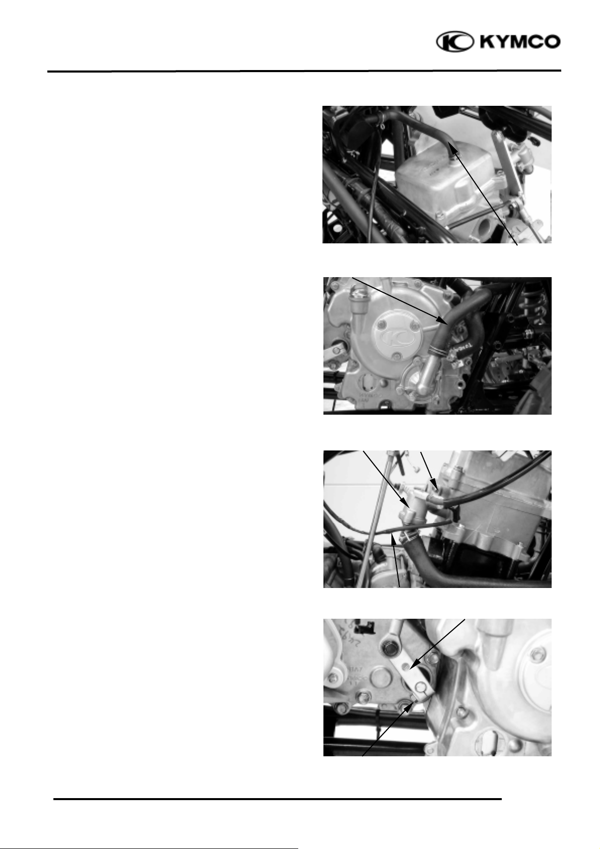
Disconnect the oil recycle tube at the
cylinder head cover.
Disconnect the water hose from water
pump cover.
Remove the bolt at the thermostat and
disconnect the thermosensor wire, then
disconnect the thermostat from the cylinder
head.
Remove the bolt at the drive select arm, then
disconnect the drive select arm from engine
assembly.
Oil Recycle Tube
Water Hose
Bolt
Thermosensor Wire
Thermostat
Drive Select Arm
Bolt
Page 4

6. ENGINE REMOVAL/INSTALLATION
6-3
Mongoose/KXR 250
Disconnect the speedometer cable (ON
ROAD only).
Remove the three bolts at the drive sprocket
cover and then remove the drive sprocket
cover.
Remove the two bolts on the drive sprocket.
Remove the drive sprocket and washer.
Slide the rubber sleeve back to expose the
starter motor wire nut.
Remove the starter motor wire nut for
disconnect the starter motor wire.
Remove the bolt at the starter motor for
disconnect the ground wire lead.
Bolts
Drive Sprocket Cover
Bolts
Drive Sprocket
Rubber Sleeve
Nut
Bolt
Ground Wire
Speedometer Cable
Page 5

6. ENGINE REMOVAL
6-4
Mongoose/KXR 250
Remove the A.C.Generator, pulser and gear
change switch couplers.
Disconnect the spark plug cap.
Remove the three bolts and remove the
outlet hose cover.
Unscrew the clamp and then disconnect the
outlet hose from the left crankcase cover.
Unscrew the clamp and then disconnect the
inlet hose from the left crankcase cover.
Gear Change Switch coupler
A.C.Generator coupler
Pulser coupler
Spark Plug Cap
Bolts
Outlet Hose Cover
Screw
Screw
Outlet Hose
Inlet Hose
Page 6

6. ENGINE REMOVAL/INSTALLATION
6-5
Mongoose/KXR 250
Remove the two bolts at the left foot peg
attaching the left floor board holder and
remove the nut at the left floor board holder,
then remove the left floor board holder.
Remove the two bolts at the right foot peg
attaching the right floor board holder.
Remove the nut at the right floor board
holder and bolt attaching the reservoir
protection cover, then remove the right floor
board holder.
Remove the two nuts and then remove the
drive select lever.
Remove the two bolts at the left front
fender holder for remove the left front
fender holder.
Bolts
Nut
Nut
Bolts
Bolt
Reservoir protection Cover
Nuts
Drive Select Lever
Left Front Fender Holder
Bolts
Page 7

6. ENGINE REMOVAL
6-6
Mongoose/KXR 250
Remove the rear lower mounting bolt and
nut.
Remove the rear upper mounting bolt and
nut.
Remove the front mounting bolts and nuts.
Remove the four bolts for remove the left
and right engine brackets.
Remove the engine assembly to the left side
of the machine.
Mounting Bolt and Nut
Mounting Bolt and Nut
Mounting Bolt and Nut
Bolts
Brackets
Page 8

6. ENGINE REMOVAL/INSTALLATION
6-7
Mongoose/KXR 250
 Loading...