

Page 1

7. CYLINDER HEAD/VALVES
7-0
Mongoose/KXR 250
7
__________________________________________________________________________________
__________________________________________________________________________________
__________________________________________________________________________________
__________________________________________________________________________________
__________________________________________________________________________________
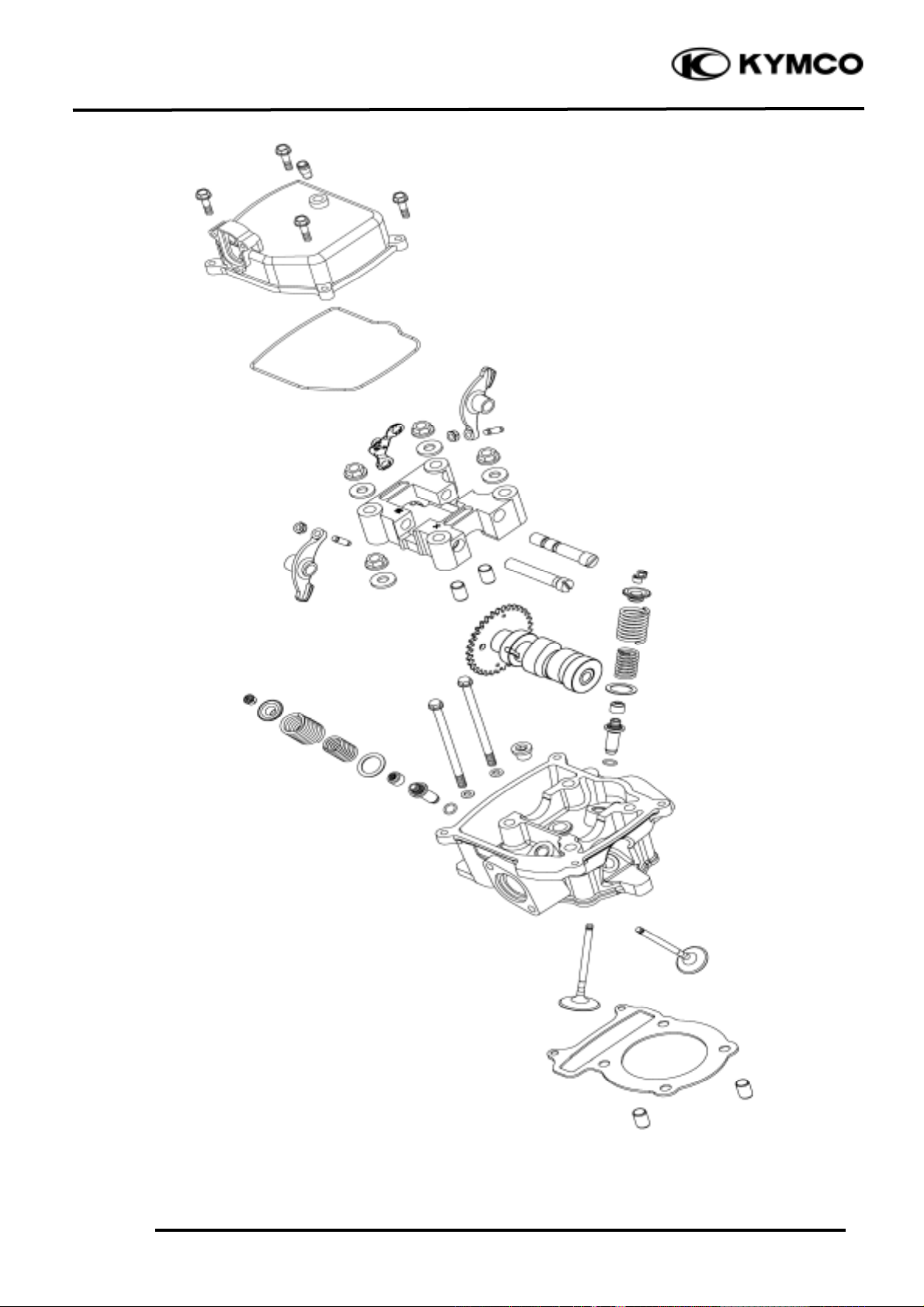
CYLINDER HEAD/VALVES
__________________________________________________________________________________
SERVICE INFORMATION -------------------------------------------- 7- 2
TROUBLESHOOTING ------------------------------------------------- 7- 3
CYLINDER HEAD COVER-------------------------------------------- 7- 4
CAMSHAFT/CAMSHAFT HOLDER --------------------------------- 7- 4
CYLINDER HEAD------------------------------------------------------ 7- 9
7
Page 2
7. CYLINDER HEAD/VALVES
7-1
Mongoose/KXR 250
Page 3
7. CYLINDER HEAD/VALVES
7-2
Mongoose/KXR 250
SERVICE INFORMATION
GENERAL INSTRUCTIONS
• The cylinder head can be serviced with the engine installed in the frame.
• When assembling, apply molybdenum disulfide grease or engine oil to the valve guide movable
parts, valve arm and camshaft sliding surfaces for initial lubrication.
• The camshaft is lubricated by engine oil through the cylinder head engine oil passages. Clean and
unclog the oil passages before assembling the cylinder head.
• After disassembly, clean the removed parts and dry them with compressed air before inspection.
• After removal, mark and arrange the removed parts in order. When assembling, install them in the
reverse order of removal.
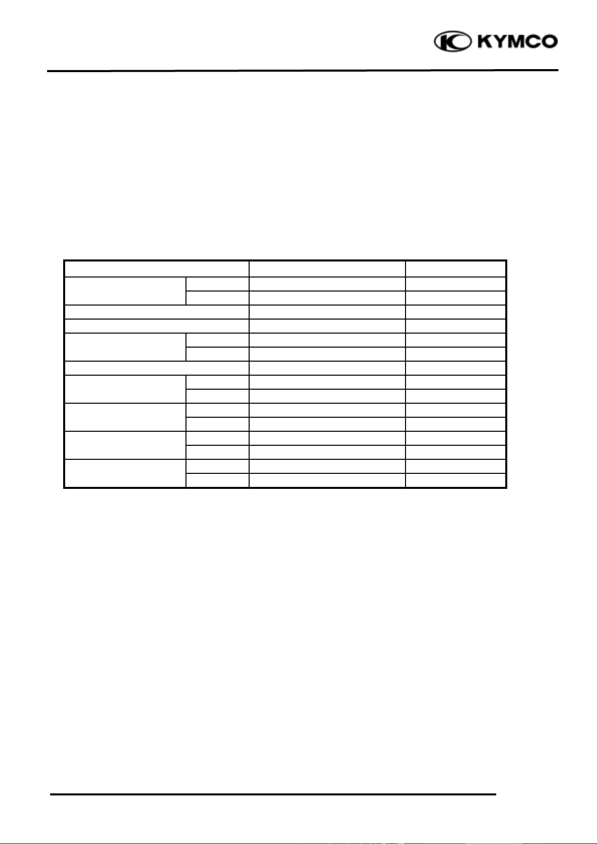
SPECIFICATIONS
Item
Standard (mm)
Service Limit (mm)
IN
0.1
æ
EX
0.1
æ
Cylinder head compression pressure
15±2kg/cm_
Cylinder head warpage
æ
0.05
IN
34.287
34.15
EX
34.1721
34.05
Valve rocker arm to shaft clearance
0.034_ 0.09
0.1
Valve stem-to-guide
IN
0.010_ 0.037
0.06
clearance
EX
0.025_ 0.052
0.08
IN
30.9
29.4
Valve spring free length
EX4139
IN
10.20_ 11.84kg(at 18.05mm)
æ
Valve spring
compressed force
EX
19.14_ 22.02kg(at 21.5mm)
æ
IN
0.8
æ
Valve spring tilt
EX
1.07
æ
Valve clearance (cold)
Camshaft cam height
Page 4

7. CYLINDER HEAD/VALVES
7-3
Mongoose/KXR 250
TORQUE VALUES
Cylinder head cover bolt 0.8_ 1.2kgf-m
Cam shaft hold nut 2.3_ 2.7kgf-m Apply engine oil to threads
Tappet adjusting nut 0.7_ 1.1kgf-m
SPECIAL TOOLS
Valve spring compressor E040
Tappet adjuster E012
TROUBLESHOOTING
• The poor cylinder head operation can be diagnosed by a compression test or by tracing engine
top-end noises.
Poor performance at idle speed White smoke from exhaust muffler
• Compression too low • Worn valve stem or valve guide
• Damaged valve stem seal
Compression too low
• Incorrect valve clearance adjustment Abnormal noise
• Burned or bend valves • Incorrect valve clearance adjustment
• Incorrect valve timing • Sticking valve or broken valve spring
• Broken valve spring • Damaged or worn camshaft
• Poor valve and seat contact • Worn cam chain guide
• Leaking cylinder head gasket • Worn camshaft and rocker arm
• Warped or cracked cylinder head
• Poorly installed spark plug
Compression too high
• Excessive carbon build-up in combustion
chamber
Page 5

7. CYLINDER HEAD/VALVES
7-4
Mongoose/KXR 250
CYLINDER HEAD COVER
REMOVAL
Remove fuel tank. (Refer to the chapter 5)
Disconnect the oil recycle tube at the
cylinder head cover.
Remove the four bolts at the cylinder head
cover, then remove the cylinder head cover.
INSTALLATION
Install a new cylinder head cover O-ring and
install the cylinder head cover.
Install and tighten the cylinder head cover
bolts.
Torque: 0.8_ 1.2kgf-m
CAMSHAFT/CAMSHAFT
HOLDER
REMOVAL
Remove the cylinder head cover. (Refer to
the cylinder head cover removal)
Remove the cam chain tensioner cap bolt
and the O-ring.
Turn the cam chain tensioner screw
clockwise to tighten it.
Cylinder Head Cover
Oil Recycle Tube
Bolts
O-ring
Be sure to install the O-ring into the
groove properly.
°Ø
Bolt
Tensioner Screw
Page 6

7. CYLINDER HEAD/VALVES
7-5
Mongoose/KXR 250
Remove the four camshaft holder nuts and
washers.
Remove the camshaft holder and dowel
pins.
Remove the camshaft gear from the cam
chain and remove the camshaft.
CAMSHAFT HOLDER DISASSEMBLY
Take out the valve rocker arm shafts.
Remove the valve rocker arms, arm shafts
and stop plate.
Diagonally loosen the cylinder head nuts
in 2 or 3 times.
°Ø
Nuts and Washers
Camshaft Holder
Camshaft
Stop Plate
Rocker Arms
Rocker Arm Shafts
Page 7

7. CYLINDER HEAD/VALVES
7-6
Mongoose/KXR 250
CAMSHAFT HOLDER INSPECTION
Inspect the camshaft holder for wear or
damage.
Inspect the rocker arm shaft for blue
discoloration or grooves.
If any defects are found, replace the rocker
arm shaft with a new one, then inspect
lubrication system.
Inspect the rocker arm bore, cam lobe
contact surface and adjuster surface for
wear/pitting/scratches/blue discoloration.
If any defects are found, replace the rocker
arm shaft with a new one, then inspect
lubrication system.
Measure each rocker arm shaft O.D.
Measure the I.D. of each valve rocker arm.
Measure arm to shaft clearance.
Replace as a set if out of specification.
Service limits: 0.10mm
Camshaft Holder
Rocker Arm Shafts
Rocker Arm Bore
Contact Surface
Adjuster Surface
Page 8

7. CYLINDER HEAD/VALVES
7-7
Mongoose/KXR 250
CAMSHAFT HOLDER ASSEMBLY
Reverse the “CAMSHAFT HOLDER
DISASSEMBLY” procedures.
CAMSHAFT INSPECTION
Check each camshaft bearing for play or
damage. Replace the camshaft assembly
with a new one if the bearings are noisy or
have excessive play.
Inspect camshaft lobes for
pitting/scratches/blue discoloration.
Measure the cam lobe height.
Service Limits:
IN : 34.15mm replace if below
EX: 34.05mm replace if below
If any defects are found, replace the
camshaft with a new one, then inspect
lubrication system.
Camshaft Bearings
Align the cross cutout on the exhaust
valve rocker arm shaft with the bolt of
the camshaft holder.
°Ø
Page 9

7. CYLINDER HEAD/VALVES
7-8
Mongoose/KXR 250
INSTALLATION
Reverse the “CAMSHAFT REMOVAL”
procedures.
Note the following points:
1. Turn the flywheel so that the “T” mark
on the flywheel aligns with the index
mark on the crankcase.
Keep the round hole on the camshaft gear
facing up and align the punch marks on
the camshaft gear with the cylinder head
surface (Position the intake and exhaust
cam lobes down.) and install the camshaft
onto the cylinder head. (Refer to the
“VALVE CLEARANCE” section in the
chapter 3)
Install the camshaft dowel pins and
holder.
Torque:
Cam shaft hold nut: 2.3_ 2.7kgf-m Apply engine oil to threads
2. Turn the cam chain tensioner screw
counter-clockwise to release it.
Apply engine oil to a new O-ring and
install it.
Tighten the cam chain tensioner cap bolt.
3. Adjust the valve clearance. (Refer to the
“VALVE CLEARANCE” section in the
chapter 3)
• Apply engine oil to the threads
of the cylinder head nuts.
• Diagonally tighten the cylinder
head nuts in 2_ 3 times.
°Ø
Be sure to install the O-ring into the
groove properly.
°Ø
Dowel Pins
Page 10

7. CYLINDER HEAD/VALVES
7-9
Mongoose/KXR 250
CYLINDER HEAD
REMOVE
Remove the camshaft. (Refer to the
“camshaft remove” section in the chapter 7)
Remove the carburetor. (Refer to the
“carburetor remove” section in the chapter
5)
Remove the exhaust muffler. (Refer to the
“exhaust muffler remove” section in the
chapter 2)
Remove the two bolts and then remove the
carburetor intake manifold.
Remove the bolt and disconnect the
thermostat.
Remove the two cylinder head bolts.
Remove the cylinder head.
CYLINDER HEAD DISASS EMBLY
Remove the valve spring cotters, retainers,
springs, spring seats, oil seals and valves
using a valve spring compressor.
Valve Spring Compressor E040
Bolts
Intake Manifold
Bolt
Bolt
Bolts
Valve Cotter
Retainer
Springs
Springs Seat
Oil Seal
Valve
Spring Compressor
• Be sure to compress the valve
springs with a valve spring compressor.
• Mark all disassembled parts to
ensure correct reassembly.
°Ø
Special
Page 11

7. CYLINDER HEAD/VALVES
7-10
Mongoose/KXR 250
VALVE /VALVE GUIDE INSPECTION
Inspect each valve for bending, burning,
scratches or abnormal stem wear.
If any defects are found, replace the valve
with a new one.
Check valve movement in the guide.
Measure each valve stem O.D.
Measure each valve guide I.D.
Subtract each valve stem O.D. from the
corresponding guide I.D. to obtain the stemto-guide clearance.
Service limits: IN : 0.06mm replace if over
EX: 0.08mm replace if over
CYLINDER HEAD INPECTION
Check the spark plug hole and valve areas
for cracks.
Check the cylinder head for warpage with a
straight edge and feeler gauge.
Service Limit: 0.05mm repair or replace if
over
VALVE SPRING INSPECTION
Measure the free length of the inner and
outer valve springs.
Service Limit:
Inner: 29.4mm replace if below
Outer: 39mm replace if below
If the stem-to-guide clearance exceeds the
service limits, replace the cylinder head
as necessary.
°Ø
Page 12

7. CYLINDER HEAD/VALVES
7-11
Mongoose/KXR 250
Measure compressed force (valve spring)
and installed length.
Replace if out of specification.
Service limits:
IN : 10.20_ 11.84kg(at 18.05mm)
EX : 19.14_ 22.02kg(at 21.5mm)
Measure the spring tilt.
Replace if out of specification.
Service limits: IN : 0.8mm
EX : 1.07mm
Page 13

7. CYLINDER HEAD/VALVES
7-12
Mongoose/KXR 250
ASSEMBLY
Install the valve spring seats and oil seal.
Lubricate each valve with engine oil and
insert the valves into the valve guides.
Install the valve springs and retainers.
Compress the valve springs using the valve
spring compressor, then install the valve
cotters.
Valve Spring Compressor E040
Tap the valve stems gently with a plastic
hammer for 2_ 3 times to firmly seat the
cotters.
INSTALLATION
Install the dowel pins and a new cylinder
head gasket.
Reverse the “CYLINDER HEAD
REMOVAL” procedures.
Torque:
Cylinder head bolt: 0.8_ 1.2kgf-m
Dowel Pins
Gasket
• When assembling, a valve spring
compressor must be used.
• Install the cotters with the
pointed ends facing down from the
upper side of the cylinder head.
°Ø
Special
Be sure to install new oil seal.
°Ø
Be careful not to damage the valves.
°Ø
 Loading...