

Page 1

9. DRIVE AND DRIVEN PULLEYS
9-0
Mongoose/KXR 250
9
DRIVE AND DRIVEN PULLEYS
SERVICE INFORMATION ...........................................................9-2
TROUBLESHOOTING .................................................................9-2
LEFT CRANKCASE COVER ........................................................9-3
DRIVE PULLEY ..........................................................................9-4
CLUTCH/DRIVEN PULLEY.........................................................9-7
9
Page 2
9. DRIVE AND DRIVEN PULLEYS
9-1
Mongoose/KXR 250
Page 3
9. DRIVE AND DRIVEN PULLEYS
9-2
Mongoose/KXR 250
SERVICE INFORMATION
GENERAL INSTRUCTIONS
• The drive pulley, clutch and driven pulley can be serviced with the engine installed in the frame.
• Avoid getting grease and oil on the drive belt and pulley faces. Remove any oil or grease from
them to minimize the slipping of drive belt and drive pulley.
SPECIFICATIONS
Item
Standard (mm)
Service Limit (mm)
Movable drive face bushing I.D.
26.989_ 27.052
27.06
Drive face collar O.D.
26.96_ 26.974
26.94
Drive belt width
23.6_ 24.4
22
Clutch lining thickness
æ
0.5
Clutch outer I.D.
153.0_ 153.2
153.5
Driven face spring free length
æ
131
Driven face O.D.
39.965_ 39.985
39.94
Movable driven face I.D.
40.000_ 40.025
40.06
Weight roller O.D.
22.92_ 23.08
22.8
TORQUE VALUES
Drive face nut 9.0_ 10.0kgf-m
Clutch outer nut 5.0_ 6.0kgf-m
Drive plat nut 5.0_ 6.0kgf-m
SPECIAL TOOLS
Universal holder E017 Clutch spring compressor E027
Bearing puller E008 Oil seal and bearing install E014
TROUBLESHOOTING
Engine starts but motorcycle won’t move Lack of power
• Worn drive belt • Worn drive belt
• Broken ramp plate • Weak driven face spring
• Worn or damaged clutch lining • Worn weight roller
• Broken driven face spring • Fouled drive face
Engine stalls or motorcycle creeps
• Broken clutch weight spring
Page 4
9. DRIVE AND DRIVEN PULLEYS
9-3
Mongoose/KXR 250
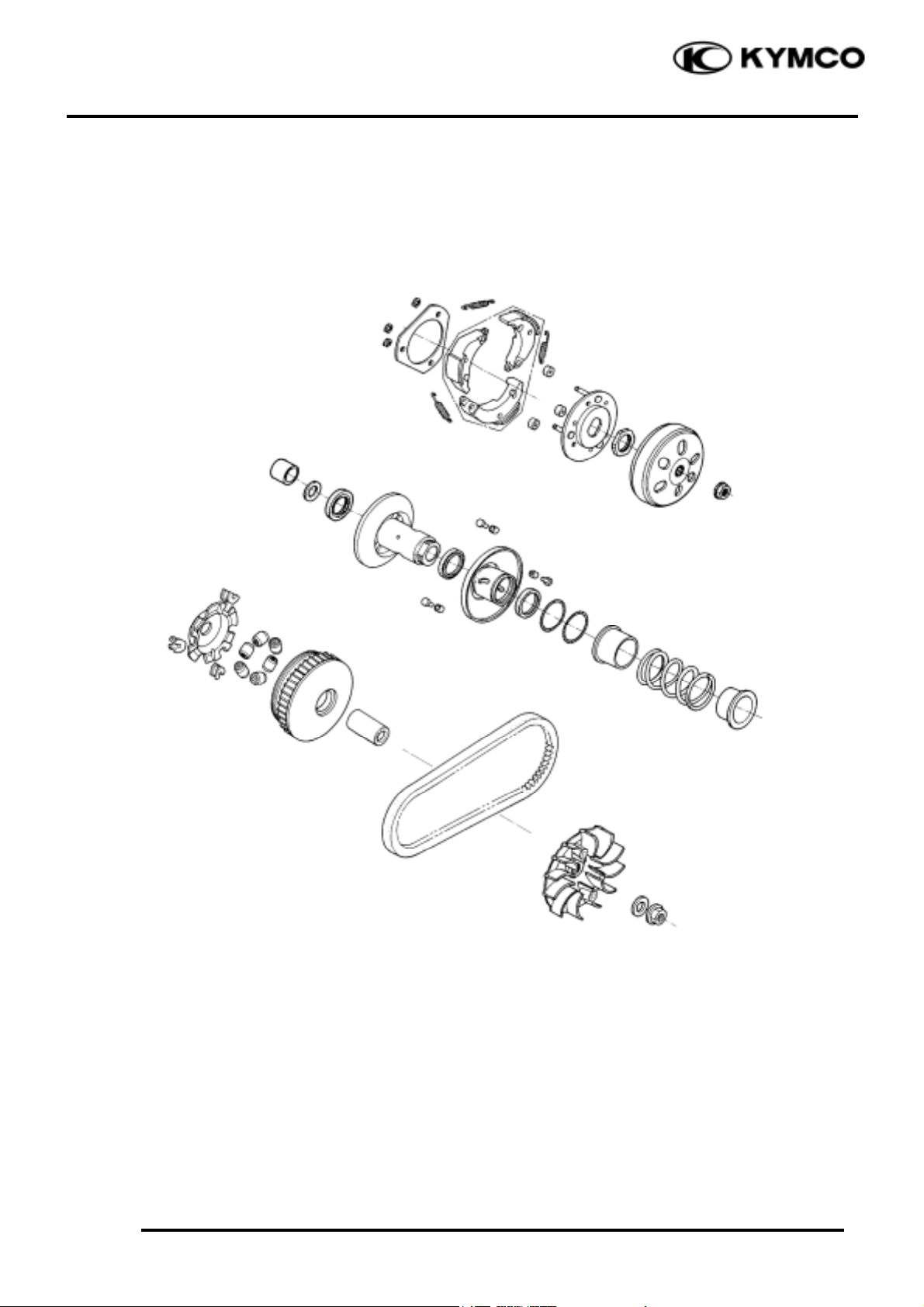
LEFT CRANKCASE COVER
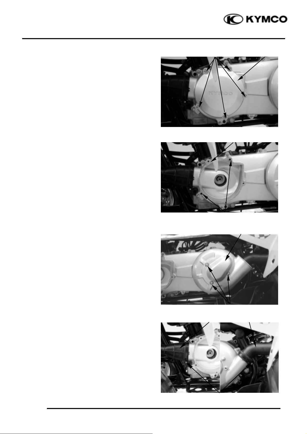
REMOVAL
Remove the five bolts.
Remove the starting cover.
Remove the dowel pins and gasket.
Remove the three bolts.
Remove the outlet hose cover.
Loosen the drive belt air inlet and outlet hose
band screws and disconnect them from the
left crankcase cover.
Bolts
Starting Cover
Dowel Pins
Gasket
Bolts
Outlet Hose Cover
Screws
Inlet Hose
Outlet Hose
Page 5
9. DRIVE AND DRIVEN PULLEYS
9-4
Mongoose/KXR 250
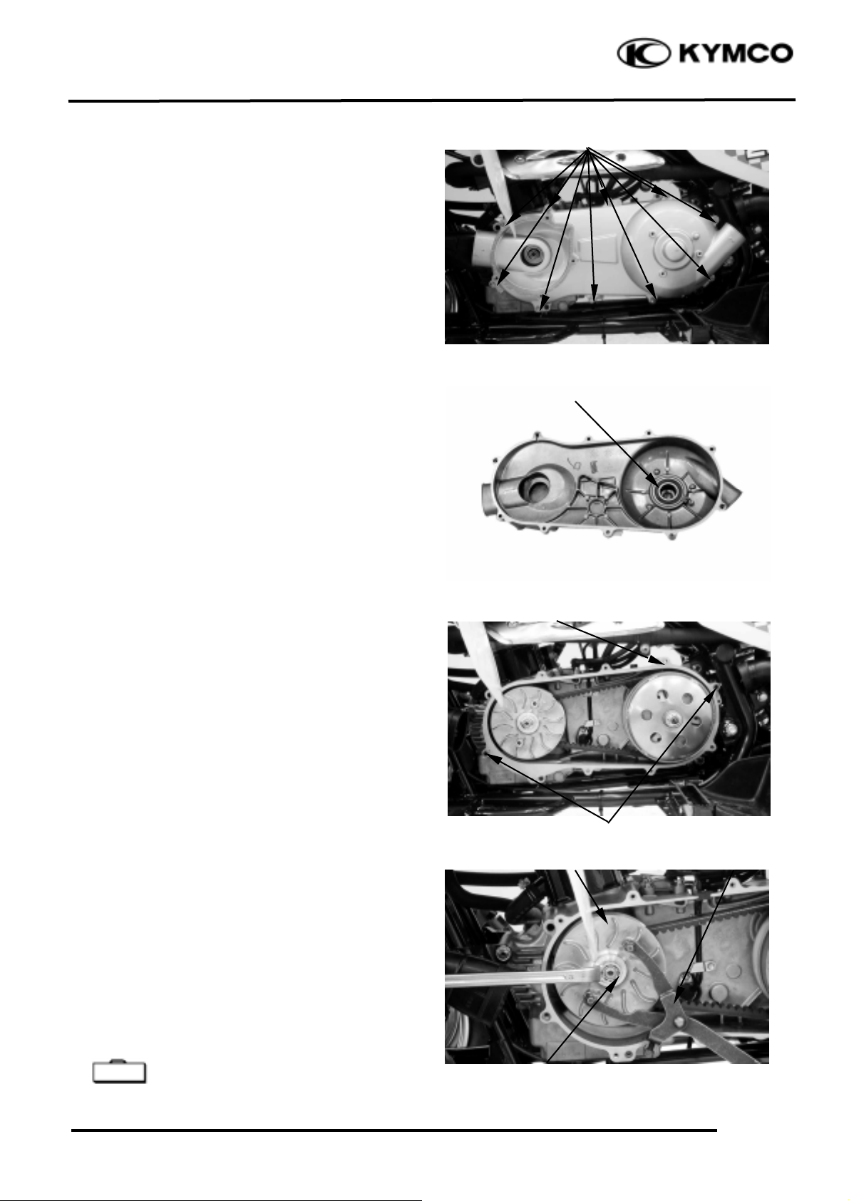
Remove the left crankcase cover bolts and left
crankcase cover.
Remove the gasket and dowel pins.
INSPECTION
Inspect the bearing for allow play in the left
crankcase cover or the bearing turns roughly _
Replace.
INSTALLATION
Install the dowel pins and new gasket.
Reverse the “LEFT CRANKCASE COVER
REMOVAL” procedures.
Install the left crankcase cover and tighten the
bolts.
Connect the drive belt air inlet and outlet hose
and tighten band screws.
Install the starting cover and outlet hose
cover.
DRIVE PULLEY
REMOVAL
Remove the left crankcase cover. (Refer to the
“LEFT CRANKCASE COVER
REMOVAL” section in the chapter 9)
Hold the drive pulley using a universal
holder and remove the drive face nut and
washer.
Remove the drive pulley.
Universal Holder E017
Bolts
Bearing
Dowel Pins
Gasket
Special
Drive Pulley
Nut
Universal Holder
Page 6
9. DRIVE AND DRIVEN PULLEYS
9-5
Mongoose/KXR 250
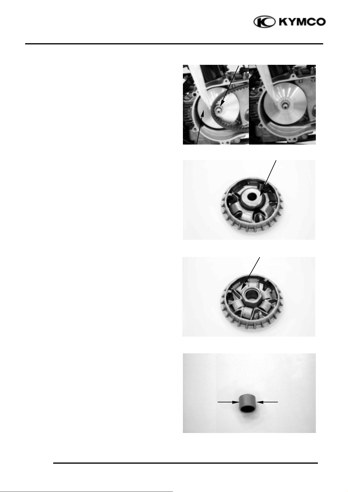
Remove the movable drive face assembly and
drive pulley collar.
DISASSEMBLY
Remove the ramp plate.
Remove the six weight rollers.
INSPECTION
Check each weight roller for wear or damage.
Measure each weight roller O.D.
Service Limit: 22.8mm replace if below.
Drive Pulley Collar
Drive Face
Ramp Plate
Roller
Page 7
9. DRIVE AND DRIVEN PULLEYS
9-6
Mongoose/KXR 250
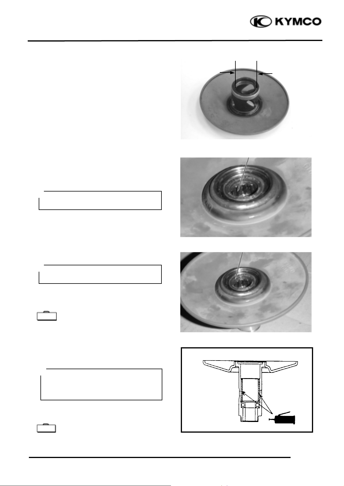
Measure the movable drive face bushing I.D.
Service Limit: 27.06mm replace if over
ASSEMBLY
Install the weight rollers into the movable
drive face.
Install the ramp plate.
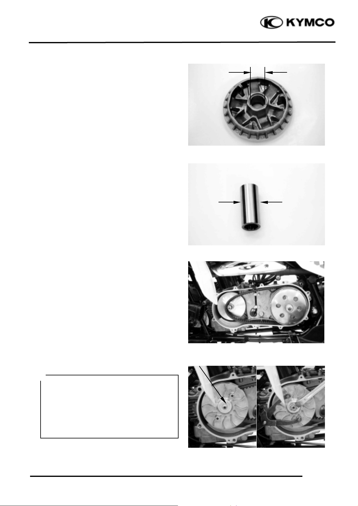
Check the drive pulley collar for wear or
damage.
Measure the O.D. of the drive pulley collar
sliding surface.
Service Limit: 26.94mm replace if below
INSTALLATION
Install the drive pulley face assembly and
collar.
Install the drive pulley, wash and nut.
Torque: 9.0_ 10.0kgf-m
Washer
When installing the drive pulley face,
compress it to let the drive belt move
downward to the lowest position so that the
drive pulley can be tightened.
Install the washer with the “OUT SIDE”
mark facing out.
Do not get oil or grease on the drive belt or
pulley faces.
°Ø
Page 8
9. DRIVE AND DRIVEN PULLEYS
9-7
Mongoose/KXR 250
CLUTCH/DRIVEN PULLEY
REMOVAL
Remove the left crankcase cover. (Refer to the
“LEFT CRANKCASE COVER
REMOVAL” section in the chapter 9)
Remove the drive pulley. (Refer to the
“DRIVE PULLEY REMOVAL” section in
the chapter 9)
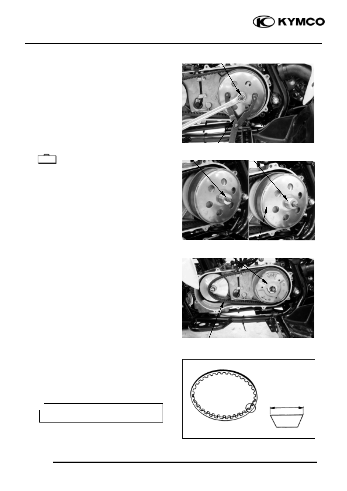
Hold the clutch outer with the universal
holder and remove the clutch outer nut.
Universal Holder E017
Remove the wash, collar and clutch outer.
Remove the clutch/driven pulley and drive
belt.
DRIVE BELT INSPECTION
Check the drive belt for cracks, separation or
abnormal or excessive wear.
Measure the drive belt width.
Service Limit: 22.0mm replace if below
Washer
Nut
Universal Holder
Collar
Clutch Outer
Clutch/Driven Pulley
Drive Belt
Special
Use specified genuine parts for replacement.
°Ø
Page 9

9. DRIVE AND DRIVEN PULLEYS
9-8
Mongoose/KXR 250
CLUTCH OUTER INSPECTION
Inspect the clutch outer for wear or damage.
Measure the clutch outer I.D.
Service Limit: 153.5mm replace if over
CLUTCH/DRIVEN PULLEY
DISASSEMBLY
Hold the clutch/driven pulley assembly with
the clutch spring compressor.
Clutch Spring Compressor E027
Set the clutch spring compressor in a vise and
remove the clutch drive plate nut.
Loosen the clutch spring compressor and
disassemble the clutch/driven p ulley assembly.
Remove the seal collar.
Pull out the guide roller pins and guide rollers.
Remove the movable driven face from the
driven face.
Clutch Spring Compressor
Lock Nut Wrench
Movable Driven Face
Guide Roller Pin
O-ring
Special
Be sure to use a clutch spring
compressor to avoid spring damage.
°Ø
Page 10
9. DRIVE AND DRIVEN PULLEYS
9-9
Mongoose/KXR 250
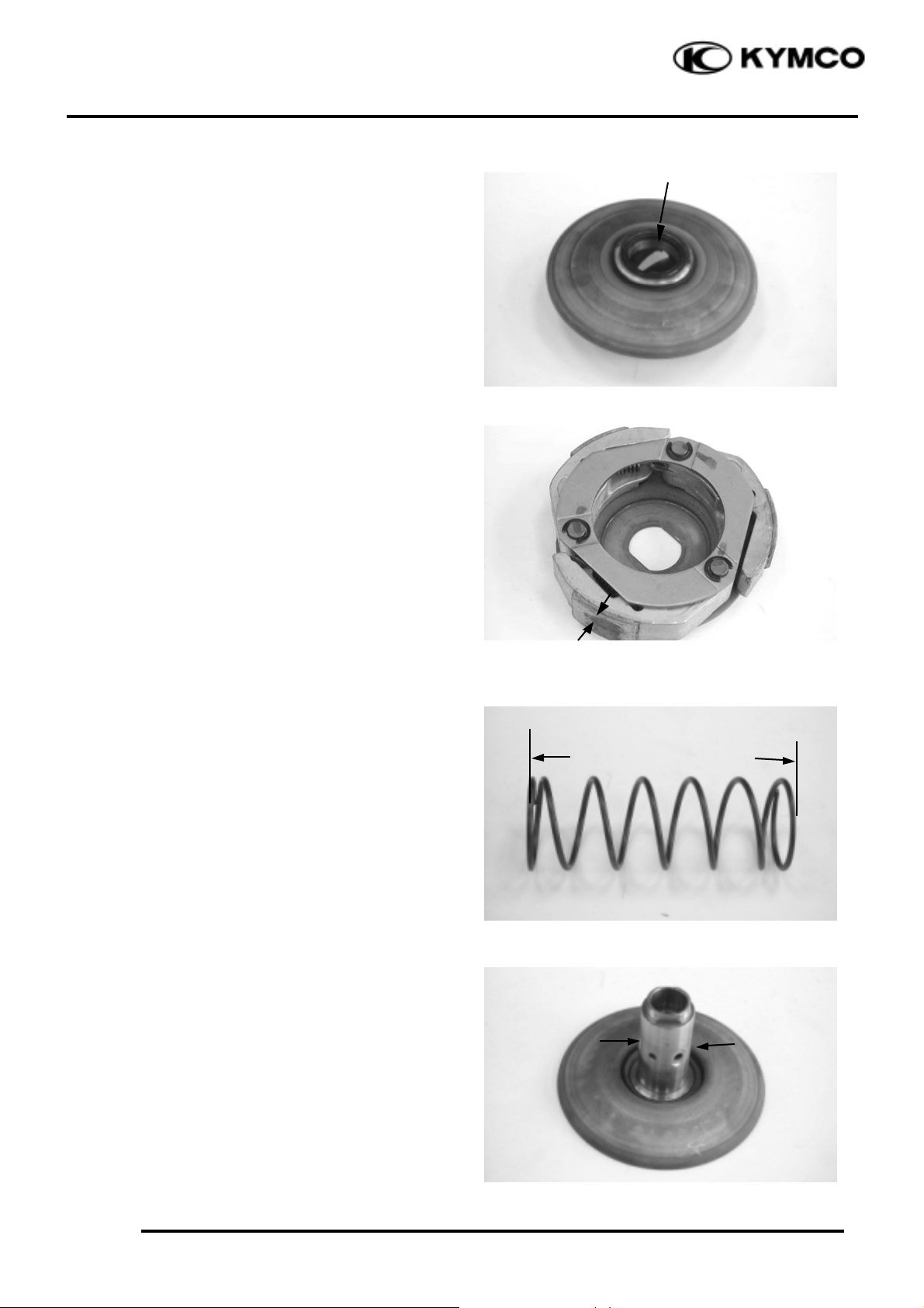
Remove the oil seal from the movable driven
face.
Measure the clutch lining thickness.
Service Limit: 0.5mm replace if below
INSPECTION
Measure the driven face spring free length.
Service Limit: 131mm replace if below
Check the driven face for wear or damage.
Measure the driven face O.D.
Service Limit: 39.94mm replace if below
Oil Seal
Page 11
9. DRIVE AND DRIVEN PULLEYS
9-10
Mongoose/KXR 250
Check the movable driven face for wear or
damage.
Measure the movable driven face I.D.
Service Limit: 40.06mm replace if over
DRIVEN PULLEY FACE BEARING
REPLACEMENT
Drive the inner needle bearing out of the
driven pulley face.
Remove the snap ring and drive the outer
bearing out of the driven face.
Apply grease to the outer bearing.
Drive a new outer bearing into the driven face
with the sealed end facing up.
Bearing Puller E008
Seat the snap ring in its groove.
Apply grease to the driven face bore areas.
Press a new needle bearing into the driven
face.
Oil Seal And Bearing Install E014
Inner Bearing
Outer Bearing
Discard the removed bearing and replace
with a new one.
°Ø
Special
Pack all bearing cavities with proper
grease.
Specified grease: Heat resistance 230°C
°Ø
Special
Discard the removed bearing and replace
with a new one.
°Ø
Page 12
9. DRIVE AND DRIVEN PULLEYS
9-11
Mongoose/KXR 250
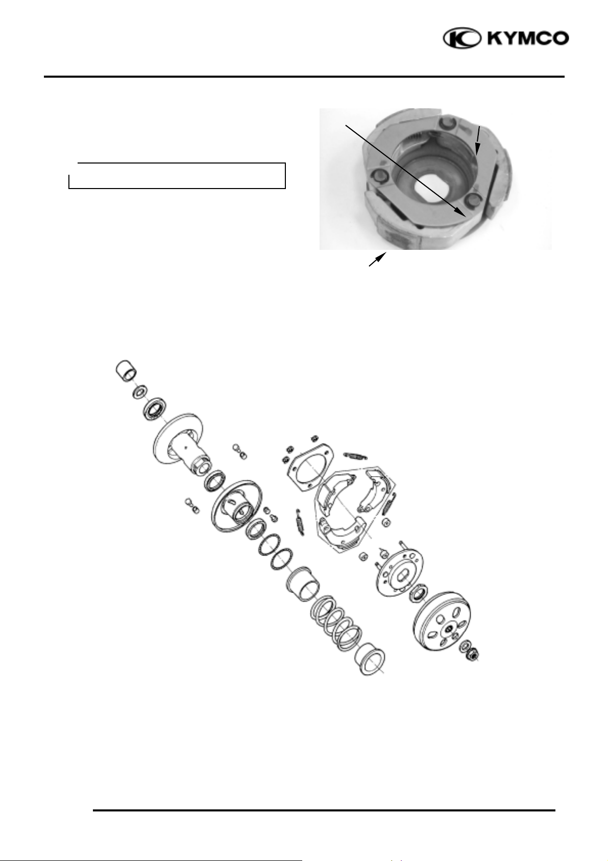
CLUTCH DISASSEMBLY
Remove the circlips and retainer plate to
disassemble the clutch.
CLUTCH / DRIVEN PULLEY ASSEMBLY
Circlip
Retainer Plate
Clutch Lining
Keep grease off the clutch linings.
°Ø
Page 13

9. DRIVE AND DRIVEN PULLEYS
9-12
Mongoose/KXR 250
Install the damper rubbers on the drive plate
pins.
Install the clutch weights/shoes and clutch
springs onto the drive plate.
Install the retainer plate and secure with the
circlips.
Clean the driven pulley faces and remove any
grease from them.
Install the oil seal onto the moveable driven
face.
Apply grease to the Oil seal and install them
onto the moveable driven face.
Install the movable driven face onto the
driven face.
Apply grease to the guide rollers and guide
roller pins and then install them into the holes
of the driven face.
Install the seal collar.
Remove any excessive grease.
Set the driven pulley assembly, driven face
spring and clutch assembly onto the clutch
spring compressor.
Compress the clutch spring compressor and
install the drive plate nut.
Set the clutch spring compressor in a vise and
tighten the drive plate nut to the specified
torque.
Torque: 5.0_ 6.0kgf-m
Clutch Spring Compressor E027
Be sure to clean the driven face off any
grease.
°Ø
Align the flat surface of the driven face
with the flat on the clutch drive plate.
°Ø
Be sure to use a clutch spring
compressor to avoid spring damage.
°Ø
Special
Page 14

9. DRIVE AND DRIVEN PULLEYS
9-13
Mongoose/KXR 250
INSTALLATION
Install the clutch/driven pulley and driven belt
onto the drive shaft.
Install the clutch outer, collar and washer.
Hold the clutch outer with the flywheel
holder.
Install and tighten the clutch outer nut.
Torque: 5.0_ 6.0kg-m
Universal Holder E017
Keep grease off the drive shaft.
°Ø
Special
 Loading...