

Page 1

13. BRAKE SYSTEM
13-0
Mongoose/KXR 250
13
__________________________________________________________________________________
__________________________________________________________________________________
__________________________________________________________________________________
__________________________________________________________________________________
__________________________________________________________________________________
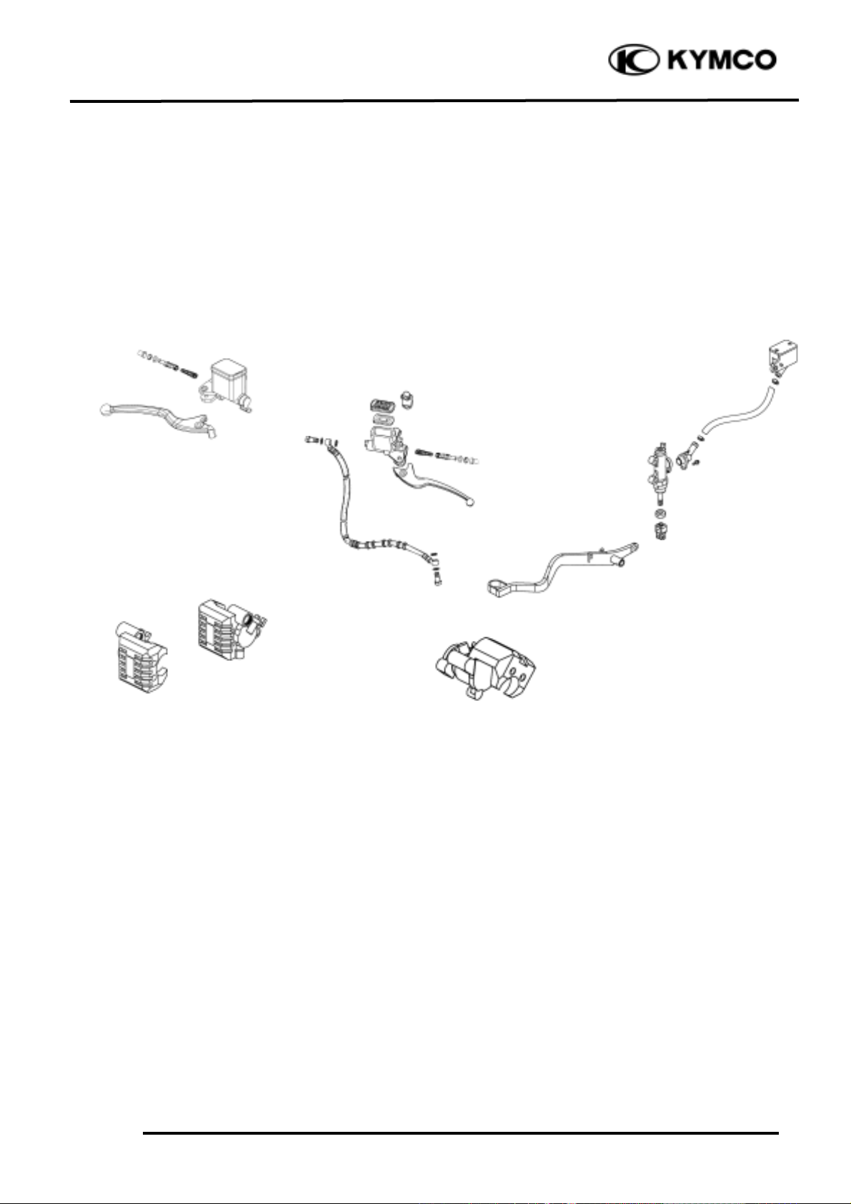
BRAKE SYSTEM
__________________________________________________________________________________
SERVICE INFORMATION -------------------------------------------- 13- 2
TROUBLESHOOTING ------------------------------------------------- 13- 3
FRONT BRAKE FLUID CHANGE/AIR BLEED -------------------- 13- 4
BRAKE MASTER CYLINDER ----------------------------------------- 13- 5
FRONT BRAKE CALIPER--------------------------------------------- 13- 8
REAR HYDRAULIC BRAKE------------------------------------------ 13-11
REAR BRAKE MASTER CYLINDER (REAR BRAKE PEDAL) ---- 13-13
REAR BRAKE CALIPER ---------------------------------------------- 13-16
13
Page 2
13. BRAKE SYSTEM
13-1
Mongoose/KXR 250
Page 3
13. BRAKE SYSTEM
13-2
Mongoose/KXR 250
SERVICE INFORMATION
GENERAL INSTRUCTIONS
• During servicing, keep oil or grease off the brake pads and brake disk.
• Drain the brake fluid from the hydraulic brake system before disassembly.
• Contaminated brake disk or brake pads reduce stopping power. Clean the contaminated brake
disk with high-performance brake degreaser and replace the brake pads.
• Do not use brake fluid for cleaning.
• Bleed air from the brake system if the brake system is removed or the brake is soft.
• Do not allow any foreign matters entering the brake reservoir when filling the brake reservoir with
brake fluid.
• Brake fluid will damage painted, coated surfaces and plastic parts. When working with brake
fluid, use shop towels to cover and protect painted, rubber and plastic parts. Wipe off any splash
of brake fluid with a clean towel. Do not wipe the machine with a towel contaminated by brake
fluid.
• Make sure to use recommended brake fluid. Use of other unspecified brake fluids may cause
brake failure.
• Inspect the brake operation before riding.
SPECIFICATIONS
Item
Standard (mm)
Service Limit (mm)
Brake disk thickness
3.8_ 4.2
3.0
Brake disk runout
æ
0.30
TROUBLESHOOTING
Loose brake lever Tight brake lever
• Air in hydraulic brake system •Seized piston
• Brake fluid level too low •Clogged hydraulic brake system
• Hydraulic brake system leakage •Smooth or worn brake pad
Poor brake performance Brake noise
• Air in brake system • Contaminated brake pad surface
• Deteriorated brake fluid • Excessive brake disk run out
• Contaminated brake pads and brake disk • Incorrectly installed caliper
• Worn brake pads • Brake disk or wheel not aligned
• Worn brake master cylinder piston oil seal
• Clogged brake fluid line Hard braking
• Deformed brake disk •Seized hydraulic brake system
• Unevenly worn brake caliper •Seized piston
Page 4

13. BRAKE SYSTEM
13-3
Mongoose/KXR 250
FRONT HYDRAULIC BRAKE
BRAKE PADS REMOVAL
Remove the front wheel. (!14-3)
Remove the two brake pad pins from the
brake caliper.
Remove the two bolts attaching the brake
caliper and then remove brake caliper.
Compress the brake caliper holder and
remove brake pads.
A wear indicator is provided on each brake.
The indicators allows checking of brake
pads wear. Check the position of the
indicator.
BRAKE DISK
Measure the brake disk thickness.
Service Limit: 3.0mm
Measure the brake disk run out.
Service Limit: 0.3mm
INSTALLATION
Reverse the “BRAKE PADS REMOVAL”
procedures.
Page 5
13. BRAKE SYSTEM
13-4
Mongoose/KXR 250
FRONT BRAKE FLUID
CHANGE/AIR BLEED
BRAKE FLUID DRAINING
Place the machine on the level ground and
set the handlebar upright.
Remove the two screws attaching the brake
fluid reservoir cap.
Connect a transparent hose to the brake
caliper bleed valve and then loosen the bleed
valve nut.
Use a syringe to draw the brake fluid out
through the hose.
BRAKE FLUID REFILLING
Connect a transparent hose and syringe to
the brake caliper bleed valve and then loosen
the bleed valve nut.
Fill the brake reservoir with brake fluid and
use the syringe to draw brake fluid into it
until there is no air bubbles in the hose.
Then, tighten the bleed valve nut.
Torque: 0.4_ 0.7kg-m
Recommended Brake Fluid: DOT-4
Use shop towels to cover plastic parts
and coated surfaces to avoid damage
caused by splash of brake fluid.
°Ø
• When drawing brake fluid with the
syringe, the brake fluid level should be
kept over 1/2 of the brake reservoir
height.
• Use only the recommended brake fluid.
°Ø
Page 6
13. BRAKE SYSTEM
13-5
Mongoose/KXR 250
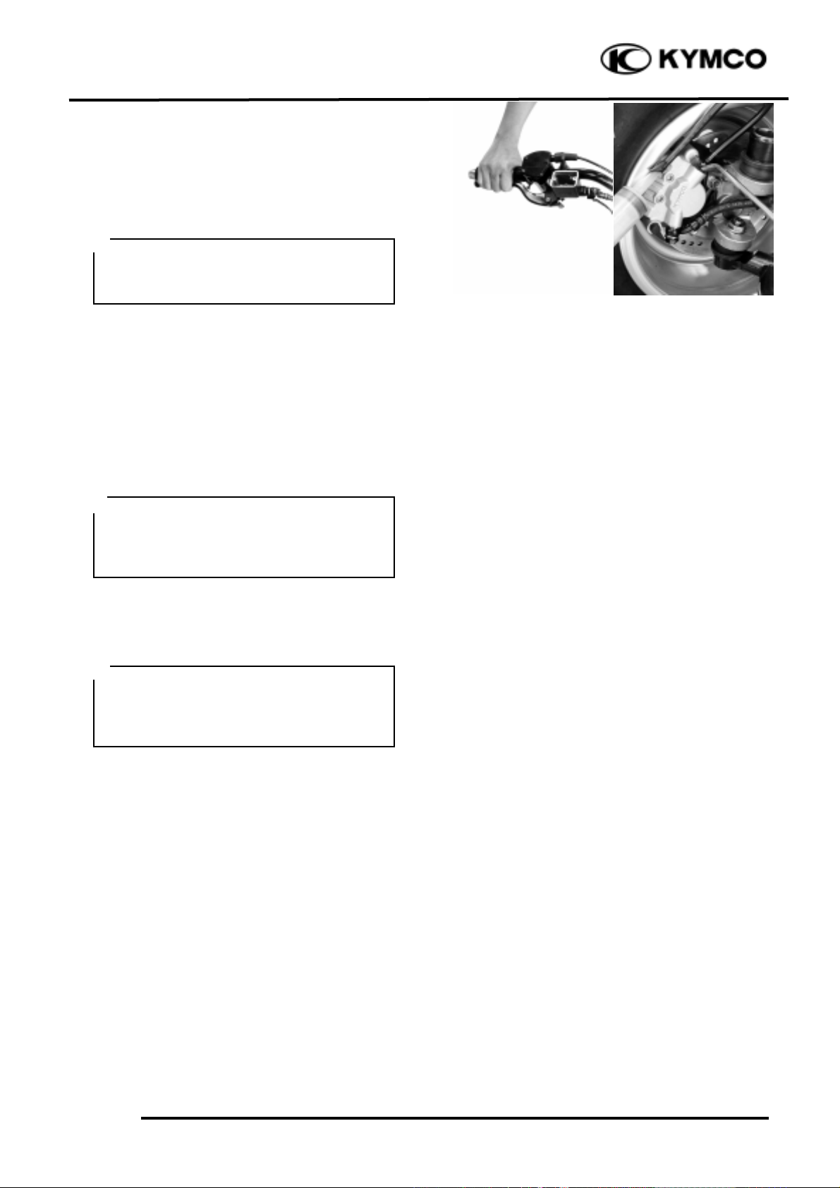
BRAKE SYSTEM BLEEDING
Connect a transparent hose to the bleed
valve and fully apply the brake lever after
continuously pull it several times. Then,
loosen the bleed valve nut to bleed air from
the brake system. Repeat these steps until
the brake system is free of air.
BRAKE MASTER CYLINDER
DISASSEMBLY
Remove the brake reservoir cover
Drain the brake fluid from the hydraulic
brake system. (!13-4)
Remove fluid tube bolt and then disconnect
the fluid tube.
Disconnect the stop light switch wires.
Remove the two master cylinder holder
bolts and remove the master cylinder.
Do not splash brake fluid onto any
rubber, plastic and coated parts. When
working with brake fluid, use shop
towels to cover these parts.
°Ø
When removing the brake fluid tube bolt,
be sure to place towels under the tube
and plug the tube end to avoid brake fluid
leakage and contamination.
°Ø
When bleeding air from the brake system,
the brake fluid level should be kept over
1/2 of the brake reservoir height.
°Ø
Page 7

13. BRAKE SYSTEM
13-6
Mongoose/KXR 250
Remove the brake lever bolt and the brake
lever.
Remove the piston rubber cover and snap
ring from the brake master cylinder.
Remove the washer, main piston and spring
from the brake master cylinder.
Clean the inside of the master cylinder and
brake reservoir with brake fluid.
INSPECTION
Check the cylinder inside wall, and spring
for scratch, corrosion or other abnormal
condition.
If any abnormal condition is found, replace
the inner parts or master cylinder.
Rubber Cover
Main Piston
Snap Ring
Spring
Master Cylinder
Snap Ring Pliers (Close)
Snap Ring
Page 8

13. BRAKE SYSTEM
13-7
Mongoose/KXR 250
ASSEMBLY
Before assembly, apply brake fluid to all
removed parts.
Install the main piston, spring and snap ring.
Install the rubber cover.
Install the brake lever.
Place the brake master cylinder on the
handlebar and install the holder with the
“UP” mark facing up. Also align the punch
mark with the holder joint seam.
First tighten the upper bolt and then tighten
the lower bolt.
Torque: 0.8_ 1.2kgf-m
Install the brake fluid tube with the
attaching bolt and two sealing washers, then
tighten the bolt.
Torque: 1.8_ 2.5kgf-m
Connect the front stop switch wire
connector.
Fill the brake reservoir with the specified
brake fluid and bleed air from the brake
system. (!13-4)
Install the brake reservoir cover.
• During assembly, the main piston and
spring must be installed as a unit
without exchange.
• When assembling the piston, soak the
cups in brake fluid for a while.
• Install the cups with the cup lips facing
the correct direction.
°Ø
Punch Mark
Holder Joint Seam
“UP” Mark
Washers
Page 9

13. BRAKE SYSTEM
13-8
Mongoose/KXR 250
FRONT BRAKE CALIPER
REMOVAL
Remove the front wheel. (!15-3)
First drain the brake fluid from the hydraulic
brake system. (!13-4)
Remove the brake pad pins.
Remove the brake fluid tube bolt.
Remove the two bolts attaching the brake
caliper.
Remove the brake caliper.
DISASSEMBLY
Remove the brake pads. (!13-3)
Remove the brake pad spring plate.
Remove the piston from the brake caliper.
If necessary, use compressed air to squeeze
out the piston through the brake fluid inlet
opening and place a shop towel under the
caliper to avoid contamination caused by the
removed piston.
Check the piston cylinder for scratches or
wear and replace if necessary.
Push the piston dust seal outward to
remove
Spring Plate
Dust Seal
Brake Pad Pins
Bolts
Fluid Tube Bolt
Page 10

13. BRAKE SYSTEM
13-9
Mongoose/KXR 250
Push the piston oil seal outward to remove
it.
Clean the seals groove with brake fluid.
INSPECTION
Inspect the caliper cylinder wall and piston
surface for scratch, corrosion or other
damages.
If any abnormal condition is noted, replace
the caliper.
ASSEMBLY
Clean all removed parts.
Apply silicon grease to the piston and oil
seals. Lubricate the brake caliper cylinder
inside wall with brake fluid.
Install the oil seal and dust seal.
Install the brake caliper piston with grooved
side facing out.
Wipe off excessive brake fluid with a clean
shop towel.
Be careful not to damage the piston
surface.
°Ø
Install the piston with its outer end
protruding 3_ 5mm beyond the brake
caliper.
°Ø
Inner Oil Seal
Page 11

13. BRAKE SYSTEM
13-10
Mongoose/KXR 250
Install the caliper spring plate into the
caliper.
INSTALLATION
Reverse the “FRONT BRAKE CALIPER
REMOVAL” procedures.
Connect the brake fluid tube to the brake
caliper and tighten the fluid tube bolt.
Torque: 1.8_ 2.5kgf-m
Fill the brake reservoir with the specified
brake fluid and bleed air from the brake
system. (!13-4)
Make sure that the boss on the caliper
correctly engages with the locating slot
on the caliper spring plate.
°Ø
When installing the brake caliper, be sure
to position the brake disk between the
two brake pads.
°Ø
When installing the brake fluid tube, be
sure to install the two sealing washers.
Page 12

13. BRAKE SYSTEM
13-11
Mongoose/KXR 250
REAR HYDRAULIC BRAKE
REAR BRAKE PADS REMOVAL
Remove the brake pads cover.
Remove the cotter pin and then pull out the
brake pad pin from the caliper.
Remove the brake spring plate and then
remove brake pads.
INSTALLATION
Reverse the “REAR BRAKE PADS
REMOVAL” procedures.
BRAKE FLUID DRAINING
Place the machine on the level ground.
Remove the two screws attaching the brake
fluid reservoir cap (brake lever and brake
pedal).
Use shop towels to cover plastic parts
and coated surfaces to avoid damage
caused by splash of brake fluid.
°Ø
• Make sure put the spring plate
big end on the rear caliper.
• Make sure put the spring plate
small end on the rear pads.
• Make sure brake pad pin over
the spring plate.
°Ø
Brake Pad Cover
Cotter Pin
Brake Pad Pin
Spring Plate
Brake Pads
Spring Plate Big End
Spring Plate Small End
Brake Pad Pin
Reservoir (Front Left Lever)
Reservoir Cover (Pedal)
Page 13

13. BRAKE SYSTEM
13-12
Mongoose/KXR 250
Connect a transparent hose to the brake
caliper bleed valve and then loosen the bleed
valve nut.
Use a syringe to draw the brake fluid out
through the hose.
BRAKE FLUID REFILLING
Connect a transparent hose and syringe to
the brake caliper bleed valve and then loosen
the bleed valve nut.
Fill the brake reservoir with brake fluid and
use the syringe to draw brake fluid into it
until there is no air bubbles in the hose.
Then, tighten the bleed valve nut.
Torque: 0.45_ 0.6kg-m
Recommended Brake Fluid: DOT-4
BRAKE SYSTEM BLEEDING
Connect a transparent hose to the bleed
valve and fully apply the brake lever (pedal)
after continuously pull it several times.
Then, loosen the bleed valve nut to bleed air
from the brake system. Repeat these steps
until the brake system is free of air.
When bleeding air from the brake system,
the brake fluid level (pedal) should be
kept over 1/2 of the brake reservoir
°Ø
• When drawing brake fluid with the
syringe, the brake fluid level (pedal)
should be kept over 1/2 of the brake
reservoir height.
• Use only the recommended brake fluid.
°Ø
Reservoir Protection
Reservoir Cover (Pedal)
Bleed Valve (Front Left Lever)
Bleed Valve (Pedal)
Reservoir (Front Left Lever)
Reservoir (Pedal)
Brake Pedal
Bleed Valve (Pedal)
Bleed Valve (Front Left Lever)
Bleed Valve (Pedal)
Page 14

13. BRAKE SYSTEM
13-13
Mongoose/KXR 250
REAR BRAKE MASTER
CYLINDER (REAR BRAKE
PEDAL)
REAR MASTER CYLINDER ON THE
LEFT HANDGRIP DISASSEMBLY
Refer to the “FRONT BRAKE MASTER
CYLINDER DISASSEMBLY” section in
the chapter 13.
ASSEMBLY
Refer to the “FRONT BRAKE MASTER
CYLINDER ASSEMBLY” section in the
chapter 13.
REAR MASTER CYLINDER ON THE
REAR BRAKE PEDAL DISASSEMBLY
Remove the brake reservoir cover.
Drain the brake fluid from the hydraulic
brake system. (!13-12)
Loosen the upper and lower nuts.
Hold the lower nut to turn clockwise and
tighten upper nut.
Turn the lower nut counterclockwise
disconnect the rear brake pedal.
Disconnect the fluid inlet tube and remove
the fluid bolt to disconnect the fluid outlet
tube.
Remove the two bolts and remove the
master cylinder.
Upper Nut
Lower Nut
Bolts
Fluid Inlet Tube
Fluid Outlet Tube
Fluid Outlet Tube Bolt
Page 15

13. BRAKE SYSTEM
13-14
Mongoose/KXR 250
Remove the screw and remove the fluid inlet
duct.
Check the O-ring for wear or damage and
replace if necessary.
Remove the two nuts and remove the seal
boot.
Remove the circlip and then pull out the
push rod, washer, piston and spring.
INSPECTION
Check the cylinder inside wall, and spring
for scratch, corrosion or other abnormal
condition.
If any abnormal condition is found, replace
the inner parts or master cylinder.
Before assembly, inspect the lst and 2nd
rubber cups for wear.
Fluid Inlet Duct
Screw
O-ring
Nuts
Seal Boot
Circlip
Push Rod
Washer
Spring
Piston
Page 16

13. BRAKE SYSTEM
13-15
Mongoose/KXR 250
ASSEMBLY
Before assembly, apply brake fluid to all
removed parts.
Reverse the “MASTER CYLINDER ON
THE REAR BRAKE PEDAL
DISASSEMBLY” procedures.
Connect the brake fluid tube to the brake
caliper and tighten the fluid tube bolt.
Torque: 1.8_ 2.5kgf-m
Fill the brake reservoir with recommended
brake fluid to the upper level.
Bleed air from the hydraulic brake system.
(!13-12)
During assembly, the master cylinder,
piston and spring must be installed as a
unit without exchange.
°Ø
Washers
Page 17

13. BRAKE SYSTEM
13-16
Mongoose/KXR 250
REAR BRAKE CALIPER
REMOVAL
Drain brake fluid of both the rear brake side
and the combination brake side. (!13-12)
Remove the brake pads. (!13-11)
Remove the caliper mounting bolts and
remover the caliper.
Remove the caliper housing bolts
Using an air blow gun, pressurize the caliper
fluid chamber to push out the piston.
Remove the dust seals and piston seals.
To prevent brake fluid from splashing on
the parts nearby, cover the parts with
cloth.
°Ø
Slightly loosen the caliper housing bolts
before removing the caliper mounting
bolts to facilitate later disassembly.
°Ø
Use care not to cause scratch on the
cylinder bore.
Do not reuse the piston seal and dust
seal that have been removed.
°Ø
Place a rag over the piston to prevent it
from popping out and flying and keep
hand off the piston.
Be careful of brake fluid which can
possibly splash.
Do not use high pressure air but
increase the pressure gradually.
°Ø
Bolts
Bolts
Seals
Piston
Page 18

13. BRAKE SYSTEM
13-17
Mongoose/KXR 250
INSPECTION
Inspect the caliper cylinder wall and piston
surface for scratch, corrosion or other
damages.
If any abnormal condition is noted, replace
the caliper.
BRAKE DISK
Measure the brake disk thickness.
Service Limit: 3.0mm
Measure the brake disk run out.
Service Limit: 0.3mm
ASSEMBLY
Reassemble the caliper in the reverse order
of disassembly procedures and observe the
following points.
Brake fluid specification and
classification: DOT4
Wash the caliper components with
fresh brake fluid before assembly. Do
not wipe off brake fluid after washing
the components.
Replace the piston seal and dust seal
with new ones with brake fluid applied.
°Ø
Page 19

13. BRAKE SYSTEM
13-18
Mongoose/KXR 250
Fit the O-ring.
Install and tighten the caliper housing bolts.
Torque: 1.8_ 2.5kgf-m
INSTALLATION
Install the rear caliper and tighten the two
mounting bolts.
With the tube ends contacted to the caliper
and install the washers and tighten the fluid
tube bolts.
Torque: 1.8_ 2.5kgf-m
Fill the system with brake fluid and bleed
air. (!13-12)
O-ring
Washers
Washers
 Loading...